EP2019183B1 - Dispositif obturateur - Google Patents
Dispositif obturateur Download PDFInfo
- Publication number
- EP2019183B1 EP2019183B1 EP08161124.6A EP08161124A EP2019183B1 EP 2019183 B1 EP2019183 B1 EP 2019183B1 EP 08161124 A EP08161124 A EP 08161124A EP 2019183 B1 EP2019183 B1 EP 2019183B1
- Authority
- EP
- European Patent Office
- Prior art keywords
- fin
- fixed
- fins
- reel
- flexible
- Prior art date
- Legal status (The legal status is an assumption and is not a legal conclusion. Google has not performed a legal analysis and makes no representation as to the accuracy of the status listed.)
- Active
Links
- 238000004804 winding Methods 0.000 claims description 14
- 239000000463 material Substances 0.000 claims description 3
- 229910000831 Steel Inorganic materials 0.000 claims description 2
- 230000005540 biological transmission Effects 0.000 claims description 2
- 230000000295 complement effect Effects 0.000 claims description 2
- 230000006835 compression Effects 0.000 claims description 2
- 238000007906 compression Methods 0.000 claims description 2
- 239000010959 steel Substances 0.000 claims description 2
- 239000004753 textile Substances 0.000 claims 1
- 229910052751 metal Inorganic materials 0.000 description 3
- 239000004033 plastic Substances 0.000 description 3
- 229920003023 plastic Polymers 0.000 description 3
- 239000002184 metal Substances 0.000 description 2
- 229920002994 synthetic fiber Polymers 0.000 description 2
- 239000002023 wood Substances 0.000 description 2
- 230000007257 malfunction Effects 0.000 description 1
- 230000008018 melting Effects 0.000 description 1
- 238000002844 melting Methods 0.000 description 1
- 229920005989 resin Polymers 0.000 description 1
- 239000011347 resin Substances 0.000 description 1
Images


Classifications
-
- E—FIXED CONSTRUCTIONS
- E06—DOORS, WINDOWS, SHUTTERS, OR ROLLER BLINDS IN GENERAL; LADDERS
- E06B—FIXED OR MOVABLE CLOSURES FOR OPENINGS IN BUILDINGS, VEHICLES, FENCES OR LIKE ENCLOSURES IN GENERAL, e.g. DOORS, WINDOWS, BLINDS, GATES
- E06B9/00—Screening or protective devices for wall or similar openings, with or without operating or securing mechanisms; Closures of similar construction
- E06B9/02—Shutters, movable grilles, or other safety closing devices, e.g. against burglary
- E06B9/06—Shutters, movable grilles, or other safety closing devices, e.g. against burglary collapsible or foldable, e.g. of the bellows or lazy-tongs type
- E06B9/0607—Shutters, movable grilles, or other safety closing devices, e.g. against burglary collapsible or foldable, e.g. of the bellows or lazy-tongs type comprising a plurality of similar rigid closing elements movable to a storage position
- E06B9/0646—Shutters, movable grilles, or other safety closing devices, e.g. against burglary collapsible or foldable, e.g. of the bellows or lazy-tongs type comprising a plurality of similar rigid closing elements movable to a storage position characterised by the relative arrangement of the closing elements in the stored position
- E06B9/0676—Shutters, movable grilles, or other safety closing devices, e.g. against burglary collapsible or foldable, e.g. of the bellows or lazy-tongs type comprising a plurality of similar rigid closing elements movable to a storage position characterised by the relative arrangement of the closing elements in the stored position stored in a stacked configuration
-
- E—FIXED CONSTRUCTIONS
- E06—DOORS, WINDOWS, SHUTTERS, OR ROLLER BLINDS IN GENERAL; LADDERS
- E06B—FIXED OR MOVABLE CLOSURES FOR OPENINGS IN BUILDINGS, VEHICLES, FENCES OR LIKE ENCLOSURES IN GENERAL, e.g. DOORS, WINDOWS, BLINDS, GATES
- E06B9/00—Screening or protective devices for wall or similar openings, with or without operating or securing mechanisms; Closures of similar construction
- E06B9/02—Shutters, movable grilles, or other safety closing devices, e.g. against burglary
- E06B9/06—Shutters, movable grilles, or other safety closing devices, e.g. against burglary collapsible or foldable, e.g. of the bellows or lazy-tongs type
- E06B9/0607—Shutters, movable grilles, or other safety closing devices, e.g. against burglary collapsible or foldable, e.g. of the bellows or lazy-tongs type comprising a plurality of similar rigid closing elements movable to a storage position
- E06B9/0615—Shutters, movable grilles, or other safety closing devices, e.g. against burglary collapsible or foldable, e.g. of the bellows or lazy-tongs type comprising a plurality of similar rigid closing elements movable to a storage position characterised by the closing elements
- E06B9/0638—Slats or panels
Definitions
- the present invention concerns closures and refers to a shutter device specially fit for windows, passages and accesses.
- Roller closures made of reciprocally articulated horizontal slats are known in order to be wound around a drum and to be unrolled for closing windows and similar.
- a disadvantage of these known closures consists in requiring bulky external cased frames for housing the drum with the wound shutter.
- Slat shutters are also known in which each slat can be rotated around its longitudinal axis at least when the shutter closes the window.
- a disadvantage of this latter closures consists in that they are very complex and expensive, moreover sometimes are subjected to malfunctions and not much reliable.
- An object of this invention is to propose a shutter device which is compact and fit to be housed, also in the opening condition of the window, in the thickness of the wall.
- Another object is to propose a shutter device which permits, in a condition of partial opening of the window, passage or access, to shadow the room delimited by the wall of the window allowing at the same time an air passage almost without obstacles in comparison with the passage of the complete opening.
- Another purpose is to propose a shutter device equipped with safety means fit to prevent housebreakings.
- Additional object is to propose a simple shutter device, relatively economical, sure and reliable.
- numeral 1 indicates the shutter device object of the present invention including a plurality of fins 2 reciprocally parallel, vertically superimposed and adjacent, for example made of metal, of wood, of wood derivatives, of synthetic materials, such as plastics or also reinforced resins, or of combination of these materials.
- Such fins are shaped elongate rectangular, each with two elongate longitudinal sides that end in correspondence of the side ends 3.
- the fins are reciprocally connected and moving between two extreme conditions of closing and opening of the window, door or passage to which the shutter device 1 is associated.
- connection between the fins 2 is realised by connecting side levers 4, for example made of rectilinear metal elements.
- the connecting levers 4 are doubled with regard to fins; a number of such levers equal to the number of fins are associated to the ends 3 of a side of fins 2 and as many levers are associated to the ends 3 of the opposite side of fins 2. In this way, such fins 2 and levers 4 make two reciprocal pantograph connection, right and left, opposite and parallel.
- each connecting lever 4 is centrally connected in revolving way to an intermediate portion of a side end 3 of a fin 2.
- the two opposite ends of such connecting lever 4 are respectively connected, in revolving way, to opposed portions of side ends 3 of contiguous fins 2, which are immediately upper and lower to the fin to which the lever 4 is centrally connected.
- each side end 3 of a defined intermediate fin 2 has each hinged end at the end of a respective lever 4, one centrally hinged to the central portion of the side end of the immediately upper fin and the other centrally hinged to the central portion of the side end of the immediately lower fin.
- the central portion of such defined intermediate fin 2 is hinged to the central portion of a third lever 4.
- Each lever 4 has a respective central seat 5 and two end seats 6, 7.
- Each side end 3 of each fin 2 has a respective central housing 8 and two end housings 9, 10, next to the longitudinal sides.
- Such seats 5, 6, 7 and housings 8, 9, 10 consist, for example in cylindrical holes housing rotation pins 11, 12, 13 almost parallel to the longitudinal dimension of fin and fit to the pantograph connection between fins and levers.
- the pins 13 contiguous to a same longitudinal side of fins have sliding means 14, consistent for example in cylinder, bushes or protrusive bearings and fit for sliding long lateral guides 15 of the device 1 so constraining a same longitudinal side of all the fins 2.
- Each side end 3 consists of an end element 16, for example carried out by forming or melting metal or plastic material, sideways fixed to the respective fin.
- Each side end 3 has a side mobile protection 17, for example consisting of a metallic or plastic plate, perpendicular to the respective fin, and fit to protect the slit between fin 2 and side guide 15 in the closing condition and able to allow fins of flanking and completely lying over in the opening condition.
- each side protection 17 is rotably connected to end element 16 in correspondence or in proximity of the sliding means 14.
- the side protection 17 has elongate triangular shape, with length approximately corresponding to the width of the fin and is hinged near the sharper top oscillating between a position in which is almost opposed to the side end 3 and one in which protrudes from it.
- Each end element 16 is equipped with an elastic means 18, for example a spiral metallic spring, acting in compression between the end element 16 and the side protection 17 for elastically maintaining this latter towards the protruding position in the closed condition and for allowing to rotate and flank to the end element 16 in the open condition
- an elastic means 18 for example a spiral metallic spring, acting in compression between the end element 16 and the side protection 17 for elastically maintaining this latter towards the protruding position in the closed condition and for allowing to rotate and flank to the end element 16 in the open condition
- the opening means 19 include two flexible lifting means 20, for example two tapes or strings for roller blind, whose lower ends are fixed to respective sides of the lower end fin 2 and whose upper ends are fixed to respective drum means 21, fixed coaxially to a horizontal winding shaft 22, which is placed on the upper part of the vertical lateral guides 15 and which is manually actuated or powered thanks to an electromotor for roller closures.
- the lateral guides 15 can be equipped with longitudinal seats for the tape or string lifting flexible means 20.
- the operation of the device provides that, in the opening condition, the lifting flexible means are wound almost completely onto the respective drums and that all the fins are adjacent and almost horizontal.
- the partial unwinding of the lifting flexible mean allows the fins to reciprocally space and to slightly tilting in order to shadow the window or door opening but leaving out almost unaltered the total light of the air passage.
- One additional unwinding of the lifting flexible means thanks to the pantograph connection, carries the fins to dispose almost vertically and with reciprocal contact so completely closing down the door or window opening.
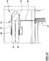
- the variant of the device of figures from 17 to 27 can be installed also horizontally and provides that the pins 13 of the side of the sliding means 14 of a fixed end fin 2 are blocked or fixed to the respective horizontal or vertical guides and that the opposite end fin 2, movable along the lateral guides 15, is connected to opening means 19 of the bi-directional type.
- the device 1 of this variant differs from the device of figures 1-16 because the opening means 19 include at least one movement flexible means 30, for example of the steel cable or synthetic fibre cable of the inextensible or high resistance type, having both ends fixed to a respective winding means 31 and having the medium section engaged in a return pulley 32 opposite to the winding means 31.
- the movable end fin 2 is fixed to one of the two sections, there and back, of the movement flexible means 30 included between the winding means 31 and the return pulley 32.
- the invention preferably provides that the opening means 19 include two parallel and lateral movement flexible means 30 whose portions placed among the respective winding means 31 and return pulley 32 are housed in channels of lateral guides 15.
- Each return pulley 32 is pivotally connected, for example by means of an idle pin, at the respective side guide 15.
- Each winding means 31 includes a reel means 33, for example cylindrical shaped, for winding, in adjacent turns, end portions of the movement flexible means 30 for a whole length of the respective wire equal at least with the run along the lateral guides 15 of the movable end fin 2.
- the wire ends that is the ends of the movement flexible means 30 are blocked to the related reel means 33 to the opposite sides of the adjacent turn assembly.
- the end portions of the movement flexible means 30 are wound in these turns in opposite directions, one into anticlockwise direction and the other portion into clockwise direction, starting from the securing points of the wire end towards the portions of such flexible means outgoing from the turns and therefore from the reel means.
- Such portions of the flexible means outgoing from the reel means are directed towards the return pulley and are adjacent and separated from a distance almost corresponding to the diameter of the reel means 33.
- Each reel means 33 is constrained to rotate around the own axis by a rotation shaft 34 manually actuated or, preferably, by a respective driving motor 35.
- Each reel means 33 is coaxial to the rotation shaft 34 with which is connected by means of respective free and rotation sliding means 36 comprising at least a longitudinal groove of the rotation shaft 34 slidingly engaged by a sliding-block means of each reel means 33 or vice-versa.
- each reel means 33 has a threaded portion 37 engaged with a complementary and coaxial fixed thread 38.
- Such threaded portion 37 and fixed threading38 have a step of screw thread principles almost equal with the turn step of the ends of the movement flexible means 30 that are wound around the respective reel means 33.
- the screw thread direction of these threaded portion 37 and fixed screw thread 38 is such as to translate the reel means 33 into direction opposite to the translation of the turns outgoing from the reel means 33 of the end portions of the movement flexible means 30.
- the operation of the variant of the device of figures 17-27 provides that both movements for opening and closing of the movable end fin are actuated by the opening means 19 in order to prevent housebreakings and to allow the operation of the device with any orientation of guides also lying horizontal on a horizontal or vertical plane.
- the opening means 19 include at least one flexible annular means, for example a chain or a cog belt, engaged with a motor toothed-crown wheel and with a transmission crown where the movable end fin is fixed to one of the portions of the at least a flexible annular means included between the two crowns.
- An advantage of this invention is to supply a shutter device which is compact and fit to be housed, also in the opening condition of the window, in the thickness of the wall.
- Another advantage is to supply a shutter device which permits, in a condition of partial opening of the window, passage or access, to shadow the room delimited by the wall of the window allowing at the same time an air passage almost without obstacles in comparison with the passage of the complete opening.
- Another advantage is to supply a shutter device equipped with safety means fit to prevent housebreakings.
- Additional advantage is to supply a shutter device which is easily to be installed also in traditional closure and pre-existing passages for substituting the traditional doors and window frames.
- Additional advantage is to supply a simple shutter device, relatively economical, sure and reliable.
Landscapes
- Engineering & Computer Science (AREA)
- Structural Engineering (AREA)
- Architecture (AREA)
- Civil Engineering (AREA)
- Operating, Guiding And Securing Of Roll- Type Closing Members (AREA)
- Seal Device For Vehicle (AREA)
- Fluid-Damping Devices (AREA)
- Vehicle Body Suspensions (AREA)
- Specific Sealing Or Ventilating Devices For Doors And Windows (AREA)
Claims (13)
- Dispositif obturateur comprenant une pluralité de lames (2) presque parallèles, ayant chacune au moins deux côtés longitudinaux allongés se terminant en correspondance des extrémités latérales (3), ces lames étant reliées de manière réciproque et mobiles entre des états extrêmes de fermeture et d'ouverture de la fenêtre, porte ou passage auquel le dispositif obturateur (1) est associé, la liaison entre les lames (2) étant réalisée par des leviers de liaison (4) reliés de manière rotative et centrale à une partie médiane d'une lame (2) et ayant les deux extrémités opposées reliées respectivement , de manière rotative, à des parties opposées des lames (2) contiguës à la lame (2) à laquelle le levier (4) est relié de manière centrale, ces lames (2) et leviers (4) réalisant une liaison à pantographe réciproque ; ledit dispositif (1) étant caractérisé par le fait que chaque extrémité latérale (3) consiste en un élément d'extrémité (16) fixé à la lame ; chaque extrémité latérale (3) a une protection latérale (17) reliée de manière rotative à l'élément d'extrémité (16) en correspondance ou à proximité des moyens de coulissement (14) ; ladite protection latérale (17) a une forme triangulaire allongée, avec une longueur correspondant approximativement à la largeur de la lame, perpendiculaire à cette dernière, et elle est articulée près du sommet plus étroit oscillant entre une position dans laquelle elle fait presque face aux extrémités latérales (3) et une position dans laquelle elle fait saillie à partir celle-ci pour protéger la fente entre la lame (2) et un guide latéral (15) dans l'état de fermeture, ledit dispositif (1) comprend en outre des moyens élastiques (18) agissant en compression entre l'élément d'extrémité (16) et la protection latérale (17) pour maintenir élastiquement cette dernière vers la position de saillie.
- Dispositif selon la revendication 1, caractérisé par le fait que les leviers de liaison (4) d'un premier sous-ensemble de leviers de liaison (4) sont associés aux extrémités latérales (3) d'un côté des lames (2) et ceux dans un second sous-ensemble sont associés aux extrémités latérales (3) du côté opposé des lames (2) réalisant deux liaison à pantographe opposées ; chaque levier (4) a un siège central respectif (5) et deux sièges d'extrémité (6, 7), chaque extrémité latérale (3) de chaque lame (2) ayant un logement central respectif (8) et deux logements d'extrémité (9, 10), à proximité des côtés longitudinaux, ces sièges (5, 6, 7) et logements (8, 9, 10) étant adaptés pour recevoir des axes de rotation (11, 12, 13) presque parallèles à la dimension longitudinale de la lame et adaptés à la liaison à pantographe entre les lames et les leviers.
- Dispositif selon la revendication 2, caractérisé par le fait que les axes (13) contigus à un même côté longitudinal de lames ont des moyens de coulissement (14) faisant saillie et adaptés pour défiler le long de guides latéraux (15) du dispositif (1).
- Dispositif selon la revendication 3, caractérisé par le fait que , au moins en correspondance d'un ensemble vertical des guides latéraux (15), les axes (13) du côté des moyens de coulissement (14) de la lame supérieure (2) sont bloqués ou fixés aux guides respectifs et la lame inférieure (2) est reliée à des moyens d'ouverture (19) ; les moyens d'ouverture (19) comprennent deux moyens flexibles de levage (20) dont les extrémités inférieures sont fixées à des côtés respectifs de la lame inférieure (2) et dont les extrémités supérieures sont fixées à des moyens de tambour respectifs (21) coaxiaux à un arbre d'enroulement (22) actionné manuellement ou motorisé ; les guides latéraux (15) ont des sièges longitudinaux pour les moyens flexibles de levage (20).
- Dispositif selon la revendication 3, caractérisé par le fait que les axes (13) du côté des moyens de coulissement (14) d'une lame d'extrémité fixe (2) sont bloqués ou fixés aux guides respectifs et la lame d'extrémité opposée (2), mobile le long des guides latéraux (15), est reliée aux moyens d'ouverture (19) ; les moyens d'ouverture (19) comprennent au moins un moyen flexible de mouvement (30) ayant les extrémités fixées à un moyen d'enroulement respectif (31) et en engagement dans une poulie de rappel (32) opposée au moyen d'enroulement (31), la lame d'extrémité mobile (2) étant fixée à l'une des parties de l'au moins un moyen flexible de mouvement (30) comprise entre le moyen d'enroulement (31) et la poulie de rappel (32).
- Dispositif selon la revendication 5, caractérisé par le fait que les moyens d'ouverture (19) comprennent deux moyens de mouvement flexibles latéraux (30) dont des parties comprises entre le moyen d'enroulement respectif (31) et la poulie de rappel (32) sont reçues dans des canaux des guides latéraux (15), chaque poulie de rappel (32) étant reliée de manière rotative au guide latéral respectif (15).
- Dispositif selon l'une quelconque des revendications 5 ou 6, caractérisé par le fait que chaque moyen d'enroulement (31) comprend un moyen de bobine (33) pour l'enroulement, en spires adjacentes, d'une longueur de moyen flexible de mouvement (30) égale au moins à la trajectoire le long des guides latéraux (15) de la lame mobile d'extrémité (2).
- Dispositif selon la revendication 7, caractérisé par le fait que les pointes d'extrémité du moyen flexible de mouvement (30) sont bloquées aux moyens de bobine respectifs (33) sur les côtés opposés de spires adjacentes, les parties d'extrémité du moyen flexible de mouvement (30) étant enroulées en les spires dans des directions opposées, chaque moyen de bobine (33) étant contraint de tourner autour de son axe par un arbre de rotation (34) actionné manuellement ou par un moteur d'entraînement respectif (35).
- Dispositif selon la revendication 8, caractérisé par le fait que chaque moyen de bobine (33) est coaxial à l'arbre de rotation (34) auquel il est relié à l'aide de moyens de coulissement à rotation et libre respectifs (36).
- Dispositif selon la revendication 9, caractérisé par le fait que les moyens de coulissement à rotation et libre (36) comprennent au moins une rainure longitudinale de l'arbre de rotation (34) en engagement coulissant par un moyen de bloc coulissant de chaque moyen de bobine (33), ou inversement.
- Dispositif selon la revendication 9 ou 10, caractérisé par le fait qu'une extrémité de chaque moyen de bobine (33) comprend une partie filetée (37) en engagement dans un filetage fixe complémentaire et coaxial (38), cette partie filetée (37) et ce filetage fixe (38) ayant un pas de principes de filetage presque identique au pas de spires des extrémités du moyen flexible de mouvement (30) enroulées autour du moyen de bobine respectif (33), la direction de filetage de cette partie filetée (37) et de ce filetage fixe (38) étant de telle façon à déplacer en translation le moyen de bobine (33) dans une direction opposée à la translation des spires quittant le moyen de bobine (33) des parties d'extrémité du moyen flexible de mouvement (30) pour maintenir presque fixe la position de ces spires de sortie et des parties en engagement dans la poulie de rappel (32).
- Dispositif selon l'une quelconque des revendications 5 à 11, caractérisé par le fait que le moyen flexible de mouvement (30) consiste en un fil d'acier ou de matière textile à allongement léger.
- Dispositif selon la revendication 5, caractérisé par le fait que les moyens d'ouverture (19) comprennent au moins un moyen annulaire flexible en engagement avec une couronne de moteur et avec une couronne de transmission, la lame d'extrémité mobile étant fixée à l'une des parties de l'au moins un moyen annulaire flexible comprise entre les deux couronnes.
Priority Applications (1)
| Application Number | Priority Date | Filing Date | Title |
|---|---|---|---|
| PL08161124T PL2019183T3 (pl) | 2007-07-25 | 2008-07-24 | Urządzenie żaluzjowe |
Applications Claiming Priority (1)
| Application Number | Priority Date | Filing Date | Title |
|---|---|---|---|
| IT000514A ITBO20070514A1 (it) | 2007-07-25 | 2007-07-25 | Dispositivo a serranda |
Publications (3)
| Publication Number | Publication Date |
|---|---|
| EP2019183A2 EP2019183A2 (fr) | 2009-01-28 |
| EP2019183A3 EP2019183A3 (fr) | 2014-12-31 |
| EP2019183B1 true EP2019183B1 (fr) | 2017-07-19 |
Family
ID=39917691
Family Applications (1)
| Application Number | Title | Priority Date | Filing Date |
|---|---|---|---|
| EP08161124.6A Active EP2019183B1 (fr) | 2007-07-25 | 2008-07-24 | Dispositif obturateur |
Country Status (6)
| Country | Link |
|---|---|
| EP (1) | EP2019183B1 (fr) |
| DK (1) | DK2019183T3 (fr) |
| ES (1) | ES2640725T3 (fr) |
| IT (1) | ITBO20070514A1 (fr) |
| PL (1) | PL2019183T3 (fr) |
| PT (1) | PT2019183T (fr) |
Family Cites Families (3)
| Publication number | Priority date | Publication date | Assignee | Title |
|---|---|---|---|---|
| US702146A (en) * | 1901-04-22 | 1902-06-10 | Edward H Mccloud | Folding door. |
| AUPP371998A0 (en) * | 1998-05-27 | 1998-06-18 | Cassar, Frank | Solid high speed door |
| US6808000B1 (en) * | 2003-05-06 | 2004-10-26 | Railtech Ltd. | Vertically movable security partition |
-
2007
- 2007-07-25 IT IT000514A patent/ITBO20070514A1/it unknown
-
2008
- 2008-07-24 PT PT81611246T patent/PT2019183T/pt unknown
- 2008-07-24 ES ES08161124.6T patent/ES2640725T3/es active Active
- 2008-07-24 DK DK08161124.6T patent/DK2019183T3/en active
- 2008-07-24 EP EP08161124.6A patent/EP2019183B1/fr active Active
- 2008-07-24 PL PL08161124T patent/PL2019183T3/pl unknown
Non-Patent Citations (1)
| Title |
|---|
| None * |
Also Published As
| Publication number | Publication date |
|---|---|
| EP2019183A3 (fr) | 2014-12-31 |
| DK2019183T3 (en) | 2017-10-23 |
| ES2640725T3 (es) | 2017-11-06 |
| EP2019183A2 (fr) | 2009-01-28 |
| ITBO20070514A1 (it) | 2009-01-26 |
| PT2019183T (pt) | 2017-11-02 |
| PL2019183T3 (pl) | 2017-12-29 |
Similar Documents
| Publication | Publication Date | Title |
|---|---|---|
| JP6674564B2 (ja) | 窓シェード | |
| CA2991504A1 (fr) | Systeme d'entrainement de tambour de cable destine a un chassis de fenetre coulissante | |
| CN104411910B (zh) | 具有两个百叶窗上轨的百叶窗 | |
| KR200477536Y1 (ko) | 상하 개폐가 가능한 블라인드 | |
| WO1994008125A9 (fr) | Ensemble de tente extensible et retractable entraine par bande | |
| WO1994008125A1 (fr) | Ensemble de tente extensible et retractable entraine par bande | |
| EP2019183B1 (fr) | Dispositif obturateur | |
| WO2004059116A1 (fr) | Stores et volets motorises | |
| EP3049604B1 (fr) | Élément de déplacement de moustiquaires, rideaux et similaires | |
| KR102647581B1 (ko) | 차양 및 그에 따른 스프링 구동 시스템 | |
| EP2703595B1 (fr) | Un store inclinable avec des glissières pour des fenêtres de toit | |
| AU2012100818B4 (en) | A window winder | |
| ES2639645T3 (es) | Mosquitera con un dispositivo de accionamiento de la cadena de guía de la malla y un sistema para facilitar el montaje y para corregir la disposición del posicionamiento | |
| NL2020994B1 (en) | Covering for an architectural feature having a bottom rail leveling mechanism | |
| AU2012100260B4 (en) | A window winder | |
| SK6462001A3 (en) | Drainage gutter | |
| EP1131530B1 (fr) | Un ensemble store | |
| JPH08177350A (ja) | ロール式網戸 | |
| JP5207397B2 (ja) | カーテン開閉装置 | |
| JP3705421B2 (ja) | 天窓用ブラインド | |
| US5179988A (en) | Rolling shutter for cover part of wall or roof opening, especially for roof window | |
| WO2021104595A1 (fr) | Agencement d'écran doté d'un dispositif de protection | |
| WO2021104594A1 (fr) | Agencement de criblage externe doté d'un élément de rappel à réglage automatique | |
| CA2096473A1 (fr) | Systeme de manoeuvre de store | |
| ITBO980091A1 (it) | Dispositivo per l'automazione della chiusura ed apertura di ante, in p articolare persiane, porte o barriere mobili. |
Legal Events
| Date | Code | Title | Description |
|---|---|---|---|
| PUAI | Public reference made under article 153(3) epc to a published international application that has entered the european phase |
Free format text: ORIGINAL CODE: 0009012 |
|
| AK | Designated contracting states |
Kind code of ref document: A2 Designated state(s): AT BE BG CH CY CZ DE DK EE ES FI FR GB GR HR HU IE IS IT LI LT LU LV MC MT NL NO PL PT RO SE SI SK TR |
|
| AX | Request for extension of the european patent |
Extension state: AL BA MK RS |
|
| PUAL | Search report despatched |
Free format text: ORIGINAL CODE: 0009013 |
|
| AK | Designated contracting states |
Kind code of ref document: A3 Designated state(s): AT BE BG CH CY CZ DE DK EE ES FI FR GB GR HR HU IE IS IT LI LT LU LV MC MT NL NO PL PT RO SE SI SK TR |
|
| AX | Request for extension of the european patent |
Extension state: AL BA MK RS |
|
| RIC1 | Information provided on ipc code assigned before grant |
Ipc: E06B 9/06 20060101AFI20141125BHEP |
|
| 17P | Request for examination filed |
Effective date: 20150630 |
|
| RBV | Designated contracting states (corrected) |
Designated state(s): AT BE BG CH CY CZ DE DK EE ES FI FR GB GR HR HU IE IS IT LI LT LU LV MC MT NL NO PL PT RO SE SI SK TR |
|
| AKX | Designation fees paid |
Designated state(s): AT BE BG CH CY CZ DE DK EE ES FI FR GB GR HR HU IE IS IT LI LT LU LV MC MT NL NO PL PT RO SE SI SK TR |
|
| AXX | Extension fees paid |
Extension state: MK Extension state: BA Extension state: AL Extension state: RS |
|
| GRAP | Despatch of communication of intention to grant a patent |
Free format text: ORIGINAL CODE: EPIDOSNIGR1 |
|
| INTG | Intention to grant announced |
Effective date: 20170215 |
|
| GRAS | Grant fee paid |
Free format text: ORIGINAL CODE: EPIDOSNIGR3 |
|
| GRAA | (expected) grant |
Free format text: ORIGINAL CODE: 0009210 |
|
| AK | Designated contracting states |
Kind code of ref document: B1 Designated state(s): AT BE BG CH CY CZ DE DK EE ES FI FR GB GR HR HU IE IS IT LI LT LU LV MC MT NL NO PL PT RO SE SI SK TR |
|
| REG | Reference to a national code |
Ref country code: GB Ref legal event code: FG4D |
|
| REG | Reference to a national code |
Ref country code: CH Ref legal event code: EP |
|
| REG | Reference to a national code |
Ref country code: IE Ref legal event code: FG4D |
|
| REG | Reference to a national code |
Ref country code: AT Ref legal event code: REF Ref document number: 910574 Country of ref document: AT Kind code of ref document: T Effective date: 20170815 |
|
| REG | Reference to a national code |
Ref country code: DE Ref legal event code: R096 Ref document number: 602008051148 Country of ref document: DE |
|
| REG | Reference to a national code |
Ref country code: FR Ref legal event code: PLFP Year of fee payment: 10 |
|
| REG | Reference to a national code |
Ref country code: NL Ref legal event code: FP |
|
| REG | Reference to a national code |
Ref country code: SE Ref legal event code: TRGR |
|
| REG | Reference to a national code |
Ref country code: DK Ref legal event code: T3 Effective date: 20171019 |
|
| REG | Reference to a national code |
Ref country code: PT Ref legal event code: SC4A Ref document number: 2019183 Country of ref document: PT Date of ref document: 20171102 Kind code of ref document: T Free format text: AVAILABILITY OF NATIONAL TRANSLATION Effective date: 20171019 |
|
| REG | Reference to a national code |
Ref country code: ES Ref legal event code: FG2A Ref document number: 2640725 Country of ref document: ES Kind code of ref document: T3 Effective date: 20171106 |
|
| REG | Reference to a national code |
Ref country code: LT Ref legal event code: MG4D |
|
| PG25 | Lapsed in a contracting state [announced via postgrant information from national office to epo] |
Ref country code: NO Free format text: LAPSE BECAUSE OF FAILURE TO SUBMIT A TRANSLATION OF THE DESCRIPTION OR TO PAY THE FEE WITHIN THE PRESCRIBED TIME-LIMIT Effective date: 20171019 Ref country code: LT Free format text: LAPSE BECAUSE OF FAILURE TO SUBMIT A TRANSLATION OF THE DESCRIPTION OR TO PAY THE FEE WITHIN THE PRESCRIBED TIME-LIMIT Effective date: 20170719 Ref country code: FI Free format text: LAPSE BECAUSE OF FAILURE TO SUBMIT A TRANSLATION OF THE DESCRIPTION OR TO PAY THE FEE WITHIN THE PRESCRIBED TIME-LIMIT Effective date: 20170719 Ref country code: HR Free format text: LAPSE BECAUSE OF FAILURE TO SUBMIT A TRANSLATION OF THE DESCRIPTION OR TO PAY THE FEE WITHIN THE PRESCRIBED TIME-LIMIT Effective date: 20170719 |
|
| PG25 | Lapsed in a contracting state [announced via postgrant information from national office to epo] |
Ref country code: LV Free format text: LAPSE BECAUSE OF FAILURE TO SUBMIT A TRANSLATION OF THE DESCRIPTION OR TO PAY THE FEE WITHIN THE PRESCRIBED TIME-LIMIT Effective date: 20170719 Ref country code: IS Free format text: LAPSE BECAUSE OF FAILURE TO SUBMIT A TRANSLATION OF THE DESCRIPTION OR TO PAY THE FEE WITHIN THE PRESCRIBED TIME-LIMIT Effective date: 20171119 Ref country code: BG Free format text: LAPSE BECAUSE OF FAILURE TO SUBMIT A TRANSLATION OF THE DESCRIPTION OR TO PAY THE FEE WITHIN THE PRESCRIBED TIME-LIMIT Effective date: 20171019 |
|
| REG | Reference to a national code |
Ref country code: GR Ref legal event code: EP Ref document number: 20170402528 Country of ref document: GR Effective date: 20180309 |
|
| REG | Reference to a national code |
Ref country code: IE Ref legal event code: MM4A |
|
| REG | Reference to a national code |
Ref country code: DE Ref legal event code: R097 Ref document number: 602008051148 Country of ref document: DE |
|
| PG25 | Lapsed in a contracting state [announced via postgrant information from national office to epo] |
Ref country code: IE Free format text: LAPSE BECAUSE OF NON-PAYMENT OF DUE FEES Effective date: 20170724 Ref country code: CZ Free format text: LAPSE BECAUSE OF FAILURE TO SUBMIT A TRANSLATION OF THE DESCRIPTION OR TO PAY THE FEE WITHIN THE PRESCRIBED TIME-LIMIT Effective date: 20170719 Ref country code: MC Free format text: LAPSE BECAUSE OF FAILURE TO SUBMIT A TRANSLATION OF THE DESCRIPTION OR TO PAY THE FEE WITHIN THE PRESCRIBED TIME-LIMIT Effective date: 20170719 Ref country code: RO Free format text: LAPSE BECAUSE OF FAILURE TO SUBMIT A TRANSLATION OF THE DESCRIPTION OR TO PAY THE FEE WITHIN THE PRESCRIBED TIME-LIMIT Effective date: 20170719 |
|
| PLBE | No opposition filed within time limit |
Free format text: ORIGINAL CODE: 0009261 |
|
| STAA | Information on the status of an ep patent application or granted ep patent |
Free format text: STATUS: NO OPPOSITION FILED WITHIN TIME LIMIT |
|
| PG25 | Lapsed in a contracting state [announced via postgrant information from national office to epo] |
Ref country code: SK Free format text: LAPSE BECAUSE OF FAILURE TO SUBMIT A TRANSLATION OF THE DESCRIPTION OR TO PAY THE FEE WITHIN THE PRESCRIBED TIME-LIMIT Effective date: 20170719 Ref country code: EE Free format text: LAPSE BECAUSE OF FAILURE TO SUBMIT A TRANSLATION OF THE DESCRIPTION OR TO PAY THE FEE WITHIN THE PRESCRIBED TIME-LIMIT Effective date: 20170719 |
|
| 26N | No opposition filed |
Effective date: 20180420 |
|
| REG | Reference to a national code |
Ref country code: FR Ref legal event code: PLFP Year of fee payment: 11 |
|
| PG25 | Lapsed in a contracting state [announced via postgrant information from national office to epo] |
Ref country code: SI Free format text: LAPSE BECAUSE OF FAILURE TO SUBMIT A TRANSLATION OF THE DESCRIPTION OR TO PAY THE FEE WITHIN THE PRESCRIBED TIME-LIMIT Effective date: 20170719 |
|
| PG25 | Lapsed in a contracting state [announced via postgrant information from national office to epo] |
Ref country code: MT Free format text: LAPSE BECAUSE OF NON-PAYMENT OF DUE FEES Effective date: 20170724 |
|
| PG25 | Lapsed in a contracting state [announced via postgrant information from national office to epo] |
Ref country code: HU Free format text: LAPSE BECAUSE OF FAILURE TO SUBMIT A TRANSLATION OF THE DESCRIPTION OR TO PAY THE FEE WITHIN THE PRESCRIBED TIME-LIMIT; INVALID AB INITIO Effective date: 20080724 |
|
| PG25 | Lapsed in a contracting state [announced via postgrant information from national office to epo] |
Ref country code: CY Free format text: LAPSE BECAUSE OF NON-PAYMENT OF DUE FEES Effective date: 20170719 |
|
| REG | Reference to a national code |
Ref country code: AT Ref legal event code: UEP Ref document number: 910574 Country of ref document: AT Kind code of ref document: T Effective date: 20170719 |
|
| PGFP | Annual fee paid to national office [announced via postgrant information from national office to epo] |
Ref country code: TR Payment date: 20230706 Year of fee payment: 16 Ref country code: IT Payment date: 20230630 Year of fee payment: 16 Ref country code: GB Payment date: 20230725 Year of fee payment: 16 Ref country code: ES Payment date: 20230816 Year of fee payment: 16 Ref country code: CH Payment date: 20230801 Year of fee payment: 16 Ref country code: AT Payment date: 20230718 Year of fee payment: 16 |
|
| PGFP | Annual fee paid to national office [announced via postgrant information from national office to epo] |
Ref country code: SE Payment date: 20230726 Year of fee payment: 16 Ref country code: PT Payment date: 20230703 Year of fee payment: 16 Ref country code: GR Payment date: 20230720 Year of fee payment: 16 Ref country code: FR Payment date: 20230725 Year of fee payment: 16 Ref country code: DK Payment date: 20230726 Year of fee payment: 16 Ref country code: DE Payment date: 20230726 Year of fee payment: 16 Ref country code: BE Payment date: 20230726 Year of fee payment: 16 |
|
| PGFP | Annual fee paid to national office [announced via postgrant information from national office to epo] |
Ref country code: PL Payment date: 20231020 Year of fee payment: 16 |
|
| PGFP | Annual fee paid to national office [announced via postgrant information from national office to epo] |
Ref country code: LU Payment date: 20240725 Year of fee payment: 17 |
|
| PGFP | Annual fee paid to national office [announced via postgrant information from national office to epo] |
Ref country code: NL Payment date: 20240725 Year of fee payment: 17 |