EP2018909B1 - Vorrichtung zur ionischen Emission - Google Patents
Vorrichtung zur ionischen Emission Download PDFInfo
- Publication number
- EP2018909B1 EP2018909B1 EP07002603.4A EP07002603A EP2018909B1 EP 2018909 B1 EP2018909 B1 EP 2018909B1 EP 07002603 A EP07002603 A EP 07002603A EP 2018909 B1 EP2018909 B1 EP 2018909B1
- Authority
- EP
- European Patent Office
- Prior art keywords
- electrode
- ions
- ionic
- face
- active
- Prior art date
- Legal status (The legal status is an assumption and is not a legal conclusion. Google has not performed a legal analysis and makes no representation as to the accuracy of the status listed.)
- Expired - Lifetime
Links
- 150000002500 ions Chemical class 0.000 claims abstract description 123
- 239000000463 material Substances 0.000 claims description 8
- 229920002635 polyurethane Polymers 0.000 claims description 6
- 239000004814 polyurethane Substances 0.000 claims description 6
- 238000009713 electroplating Methods 0.000 claims description 3
- 239000007769 metal material Substances 0.000 claims description 2
- 239000006262 metallic foam Substances 0.000 claims 1
- 239000002245 particle Substances 0.000 abstract description 81
- 239000012530 fluid Substances 0.000 abstract description 44
- 239000000443 aerosol Substances 0.000 abstract description 42
- 230000004907 flux Effects 0.000 abstract description 23
- 230000009471 action Effects 0.000 abstract description 13
- 238000009826 distribution Methods 0.000 abstract description 7
- 238000000151 deposition Methods 0.000 description 35
- 230000008021 deposition Effects 0.000 description 26
- 238000000265 homogenisation Methods 0.000 description 14
- 239000002184 metal Substances 0.000 description 14
- 229910052751 metal Inorganic materials 0.000 description 14
- PXHVJJICTQNCMI-UHFFFAOYSA-N Nickel Chemical compound [Ni] PXHVJJICTQNCMI-UHFFFAOYSA-N 0.000 description 12
- 239000000428 dust Substances 0.000 description 10
- 230000000694 effects Effects 0.000 description 9
- 230000033001 locomotion Effects 0.000 description 8
- 238000000034 method Methods 0.000 description 8
- 210000003462 vein Anatomy 0.000 description 7
- 230000001413 cellular effect Effects 0.000 description 6
- 239000004020 conductor Substances 0.000 description 6
- 238000001914 filtration Methods 0.000 description 6
- 229910052759 nickel Inorganic materials 0.000 description 6
- 230000007423 decrease Effects 0.000 description 5
- 239000012717 electrostatic precipitator Substances 0.000 description 5
- 230000006870 function Effects 0.000 description 5
- 239000000126 substance Substances 0.000 description 5
- 239000000919 ceramic Substances 0.000 description 4
- 239000011148 porous material Substances 0.000 description 4
- 230000007547 defect Effects 0.000 description 3
- 230000005686 electrostatic field Effects 0.000 description 3
- 238000004519 manufacturing process Methods 0.000 description 3
- XLYOFNOQVPJJNP-UHFFFAOYSA-N water Substances O XLYOFNOQVPJJNP-UHFFFAOYSA-N 0.000 description 3
- 230000000721 bacterilogical effect Effects 0.000 description 2
- 230000004888 barrier function Effects 0.000 description 2
- 239000003989 dielectric material Substances 0.000 description 2
- 238000004070 electrodeposition Methods 0.000 description 2
- 238000002474 experimental method Methods 0.000 description 2
- 239000011521 glass Substances 0.000 description 2
- 239000008187 granular material Substances 0.000 description 2
- 230000000704 physical effect Effects 0.000 description 2
- 238000001556 precipitation Methods 0.000 description 2
- 238000000746 purification Methods 0.000 description 2
- 230000003252 repetitive effect Effects 0.000 description 2
- 239000004065 semiconductor Substances 0.000 description 2
- 238000011144 upstream manufacturing Methods 0.000 description 2
- VHUUQVKOLVNVRT-UHFFFAOYSA-N Ammonium hydroxide Chemical compound [NH4+].[OH-] VHUUQVKOLVNVRT-UHFFFAOYSA-N 0.000 description 1
- 241000894006 Bacteria Species 0.000 description 1
- 241000195493 Cryptophyta Species 0.000 description 1
- 241000233866 Fungi Species 0.000 description 1
- 229910021205 NaH2PO2 Inorganic materials 0.000 description 1
- 241000080590 Niso Species 0.000 description 1
- CBENFWSGALASAD-UHFFFAOYSA-N Ozone Chemical compound [O-][O+]=O CBENFWSGALASAD-UHFFFAOYSA-N 0.000 description 1
- 229920000297 Rayon Polymers 0.000 description 1
- 206010070834 Sensitisation Diseases 0.000 description 1
- 241001080024 Telles Species 0.000 description 1
- 241000700605 Viruses Species 0.000 description 1
- 230000004913 activation Effects 0.000 description 1
- 235000011114 ammonium hydroxide Nutrition 0.000 description 1
- 150000001450 anions Chemical class 0.000 description 1
- 230000008901 benefit Effects 0.000 description 1
- 238000006555 catalytic reaction Methods 0.000 description 1
- 238000010276 construction Methods 0.000 description 1
- 238000012937 correction Methods 0.000 description 1
- 238000005520 cutting process Methods 0.000 description 1
- 230000001419 dependent effect Effects 0.000 description 1
- 230000003292 diminished effect Effects 0.000 description 1
- 238000007598 dipping method Methods 0.000 description 1
- 239000006185 dispersion Substances 0.000 description 1
- 238000006073 displacement reaction Methods 0.000 description 1
- 238000010410 dusting Methods 0.000 description 1
- 230000005684 electric field Effects 0.000 description 1
- 238000005868 electrolysis reaction Methods 0.000 description 1
- 238000005367 electrostatic precipitation Methods 0.000 description 1
- 239000002657 fibrous material Substances 0.000 description 1
- 230000036541 health Effects 0.000 description 1
- 230000006872 improvement Effects 0.000 description 1
- 238000005342 ion exchange Methods 0.000 description 1
- 238000009533 lab test Methods 0.000 description 1
- 230000014759 maintenance of location Effects 0.000 description 1
- 244000005700 microbiome Species 0.000 description 1
- 239000000203 mixture Substances 0.000 description 1
- 230000007935 neutral effect Effects 0.000 description 1
- LGQLOGILCSXPEA-UHFFFAOYSA-L nickel sulfate Chemical compound [Ni+2].[O-]S([O-])(=O)=O LGQLOGILCSXPEA-UHFFFAOYSA-L 0.000 description 1
- 229910000363 nickel(II) sulfate Inorganic materials 0.000 description 1
- 230000008520 organization Effects 0.000 description 1
- 238000010422 painting Methods 0.000 description 1
- XKJCHHZQLQNZHY-UHFFFAOYSA-N phthalimide Chemical compound C1=CC=C2C(=O)NC(=O)C2=C1 XKJCHHZQLQNZHY-UHFFFAOYSA-N 0.000 description 1
- 230000008569 process Effects 0.000 description 1
- 239000002964 rayon Substances 0.000 description 1
- 230000006798 recombination Effects 0.000 description 1
- 238000005215 recombination Methods 0.000 description 1
- 230000008313 sensitization Effects 0.000 description 1
- 230000035939 shock Effects 0.000 description 1
- 230000007704 transition Effects 0.000 description 1
Images


Classifications
-
- B—PERFORMING OPERATIONS; TRANSPORTING
- B03—SEPARATION OF SOLID MATERIALS USING LIQUIDS OR USING PNEUMATIC TABLES OR JIGS; MAGNETIC OR ELECTROSTATIC SEPARATION OF SOLID MATERIALS FROM SOLID MATERIALS OR FLUIDS; SEPARATION BY HIGH-VOLTAGE ELECTRIC FIELDS
- B03C—MAGNETIC OR ELECTROSTATIC SEPARATION OF SOLID MATERIALS FROM SOLID MATERIALS OR FLUIDS; SEPARATION BY HIGH-VOLTAGE ELECTRIC FIELDS
- B03C3/00—Separating dispersed particles from gases or vapour, e.g. air, by electrostatic effect
- B03C3/02—Plant or installations having external electricity supply
- B03C3/04—Plant or installations having external electricity supply dry type
- B03C3/09—Plant or installations having external electricity supply dry type characterised by presence of stationary flat electrodes arranged with their flat surfaces at right angles to the gas stream
-
- B—PERFORMING OPERATIONS; TRANSPORTING
- B01—PHYSICAL OR CHEMICAL PROCESSES OR APPARATUS IN GENERAL
- B01J—CHEMICAL OR PHYSICAL PROCESSES, e.g. CATALYSIS OR COLLOID CHEMISTRY; THEIR RELEVANT APPARATUS
- B01J19/00—Chemical, physical or physico-chemical processes in general; Their relevant apparatus
- B01J19/08—Processes employing the direct application of electric or wave energy, or particle radiation; Apparatus therefor
- B01J19/087—Processes employing the direct application of electric or wave energy, or particle radiation; Apparatus therefor employing electric or magnetic energy
- B01J19/088—Processes employing the direct application of electric or wave energy, or particle radiation; Apparatus therefor employing electric or magnetic energy giving rise to electric discharges
-
- B—PERFORMING OPERATIONS; TRANSPORTING
- B03—SEPARATION OF SOLID MATERIALS USING LIQUIDS OR USING PNEUMATIC TABLES OR JIGS; MAGNETIC OR ELECTROSTATIC SEPARATION OF SOLID MATERIALS FROM SOLID MATERIALS OR FLUIDS; SEPARATION BY HIGH-VOLTAGE ELECTRIC FIELDS
- B03C—MAGNETIC OR ELECTROSTATIC SEPARATION OF SOLID MATERIALS FROM SOLID MATERIALS OR FLUIDS; SEPARATION BY HIGH-VOLTAGE ELECTRIC FIELDS
- B03C3/00—Separating dispersed particles from gases or vapour, e.g. air, by electrostatic effect
- B03C3/34—Constructional details or accessories or operation thereof
- B03C3/38—Particle charging or ionising stations, e.g. using electric discharge, radioactive radiation or flames
-
- B—PERFORMING OPERATIONS; TRANSPORTING
- B03—SEPARATION OF SOLID MATERIALS USING LIQUIDS OR USING PNEUMATIC TABLES OR JIGS; MAGNETIC OR ELECTROSTATIC SEPARATION OF SOLID MATERIALS FROM SOLID MATERIALS OR FLUIDS; SEPARATION BY HIGH-VOLTAGE ELECTRIC FIELDS
- B03C—MAGNETIC OR ELECTROSTATIC SEPARATION OF SOLID MATERIALS FROM SOLID MATERIALS OR FLUIDS; SEPARATION BY HIGH-VOLTAGE ELECTRIC FIELDS
- B03C3/00—Separating dispersed particles from gases or vapour, e.g. air, by electrostatic effect
- B03C3/34—Constructional details or accessories or operation thereof
- B03C3/40—Electrode constructions
- B03C3/41—Ionising-electrodes
-
- B—PERFORMING OPERATIONS; TRANSPORTING
- B03—SEPARATION OF SOLID MATERIALS USING LIQUIDS OR USING PNEUMATIC TABLES OR JIGS; MAGNETIC OR ELECTROSTATIC SEPARATION OF SOLID MATERIALS FROM SOLID MATERIALS OR FLUIDS; SEPARATION BY HIGH-VOLTAGE ELECTRIC FIELDS
- B03C—MAGNETIC OR ELECTROSTATIC SEPARATION OF SOLID MATERIALS FROM SOLID MATERIALS OR FLUIDS; SEPARATION BY HIGH-VOLTAGE ELECTRIC FIELDS
- B03C3/00—Separating dispersed particles from gases or vapour, e.g. air, by electrostatic effect
- B03C3/34—Constructional details or accessories or operation thereof
- B03C3/40—Electrode constructions
- B03C3/45—Collecting-electrodes
- B03C3/47—Collecting-electrodes flat, e.g. plates, discs, gratings
-
- B—PERFORMING OPERATIONS; TRANSPORTING
- B03—SEPARATION OF SOLID MATERIALS USING LIQUIDS OR USING PNEUMATIC TABLES OR JIGS; MAGNETIC OR ELECTROSTATIC SEPARATION OF SOLID MATERIALS FROM SOLID MATERIALS OR FLUIDS; SEPARATION BY HIGH-VOLTAGE ELECTRIC FIELDS
- B03C—MAGNETIC OR ELECTROSTATIC SEPARATION OF SOLID MATERIALS FROM SOLID MATERIALS OR FLUIDS; SEPARATION BY HIGH-VOLTAGE ELECTRIC FIELDS
- B03C3/00—Separating dispersed particles from gases or vapour, e.g. air, by electrostatic effect
- B03C3/34—Constructional details or accessories or operation thereof
- B03C3/40—Electrode constructions
- B03C3/45—Collecting-electrodes
- B03C3/51—Catch- space electrodes, e.g. slotted-box form
-
- B—PERFORMING OPERATIONS; TRANSPORTING
- B03—SEPARATION OF SOLID MATERIALS USING LIQUIDS OR USING PNEUMATIC TABLES OR JIGS; MAGNETIC OR ELECTROSTATIC SEPARATION OF SOLID MATERIALS FROM SOLID MATERIALS OR FLUIDS; SEPARATION BY HIGH-VOLTAGE ELECTRIC FIELDS
- B03C—MAGNETIC OR ELECTROSTATIC SEPARATION OF SOLID MATERIALS FROM SOLID MATERIALS OR FLUIDS; SEPARATION BY HIGH-VOLTAGE ELECTRIC FIELDS
- B03C3/00—Separating dispersed particles from gases or vapour, e.g. air, by electrostatic effect
- B03C3/34—Constructional details or accessories or operation thereof
- B03C3/40—Electrode constructions
- B03C3/60—Use of special materials other than liquids
-
- B—PERFORMING OPERATIONS; TRANSPORTING
- B01—PHYSICAL OR CHEMICAL PROCESSES OR APPARATUS IN GENERAL
- B01J—CHEMICAL OR PHYSICAL PROCESSES, e.g. CATALYSIS OR COLLOID CHEMISTRY; THEIR RELEVANT APPARATUS
- B01J2219/00—Chemical, physical or physico-chemical processes in general; Their relevant apparatus
- B01J2219/08—Processes employing the direct application of electric or wave energy, or particle radiation; Apparatus therefor
- B01J2219/0803—Processes employing the direct application of electric or wave energy, or particle radiation; Apparatus therefor employing electric or magnetic energy
- B01J2219/0805—Processes employing the direct application of electric or wave energy, or particle radiation; Apparatus therefor employing electric or magnetic energy giving rise to electric discharges
- B01J2219/0807—Processes employing the direct application of electric or wave energy, or particle radiation; Apparatus therefor employing electric or magnetic energy giving rise to electric discharges involving electrodes
- B01J2219/0809—Processes employing the direct application of electric or wave energy, or particle radiation; Apparatus therefor employing electric or magnetic energy giving rise to electric discharges involving electrodes employing two or more electrodes
-
- B—PERFORMING OPERATIONS; TRANSPORTING
- B01—PHYSICAL OR CHEMICAL PROCESSES OR APPARATUS IN GENERAL
- B01J—CHEMICAL OR PHYSICAL PROCESSES, e.g. CATALYSIS OR COLLOID CHEMISTRY; THEIR RELEVANT APPARATUS
- B01J2219/00—Chemical, physical or physico-chemical processes in general; Their relevant apparatus
- B01J2219/08—Processes employing the direct application of electric or wave energy, or particle radiation; Apparatus therefor
- B01J2219/0803—Processes employing the direct application of electric or wave energy, or particle radiation; Apparatus therefor employing electric or magnetic energy
- B01J2219/0805—Processes employing the direct application of electric or wave energy, or particle radiation; Apparatus therefor employing electric or magnetic energy giving rise to electric discharges
- B01J2219/0845—Details relating to the type of discharge
- B01J2219/0849—Corona pulse discharge
-
- B—PERFORMING OPERATIONS; TRANSPORTING
- B03—SEPARATION OF SOLID MATERIALS USING LIQUIDS OR USING PNEUMATIC TABLES OR JIGS; MAGNETIC OR ELECTROSTATIC SEPARATION OF SOLID MATERIALS FROM SOLID MATERIALS OR FLUIDS; SEPARATION BY HIGH-VOLTAGE ELECTRIC FIELDS
- B03C—MAGNETIC OR ELECTROSTATIC SEPARATION OF SOLID MATERIALS FROM SOLID MATERIALS OR FLUIDS; SEPARATION BY HIGH-VOLTAGE ELECTRIC FIELDS
- B03C2201/00—Details of magnetic or electrostatic separation
- B03C2201/06—Ionising electrode being a needle
-
- B—PERFORMING OPERATIONS; TRANSPORTING
- B03—SEPARATION OF SOLID MATERIALS USING LIQUIDS OR USING PNEUMATIC TABLES OR JIGS; MAGNETIC OR ELECTROSTATIC SEPARATION OF SOLID MATERIALS FROM SOLID MATERIALS OR FLUIDS; SEPARATION BY HIGH-VOLTAGE ELECTRIC FIELDS
- B03C—MAGNETIC OR ELECTROSTATIC SEPARATION OF SOLID MATERIALS FROM SOLID MATERIALS OR FLUIDS; SEPARATION BY HIGH-VOLTAGE ELECTRIC FIELDS
- B03C2201/00—Details of magnetic or electrostatic separation
- B03C2201/10—Ionising electrode with two or more serrated ends or sides
-
- Y—GENERAL TAGGING OF NEW TECHNOLOGICAL DEVELOPMENTS; GENERAL TAGGING OF CROSS-SECTIONAL TECHNOLOGIES SPANNING OVER SEVERAL SECTIONS OF THE IPC; TECHNICAL SUBJECTS COVERED BY FORMER USPC CROSS-REFERENCE ART COLLECTIONS [XRACs] AND DIGESTS
- Y02—TECHNOLOGIES OR APPLICATIONS FOR MITIGATION OR ADAPTATION AGAINST CLIMATE CHANGE
- Y02A—TECHNOLOGIES FOR ADAPTATION TO CLIMATE CHANGE
- Y02A50/00—TECHNOLOGIES FOR ADAPTATION TO CLIMATE CHANGE in human health protection, e.g. against extreme weather
- Y02A50/20—Air quality improvement or preservation, e.g. vehicle emission control or emission reduction by using catalytic converters
- Y02A50/2351—Atmospheric particulate matter [PM], e.g. carbon smoke microparticles, smog, aerosol particles, dust
Definitions
- This homogenization of the deposition of ions on the surface of the particles may have the purpose of inflicting them mechanical, physical, chemical, energy ... consequences of controlled intensity.
- the invention relates specifically to the technical field of electrostatic emission and ion deposition devices of the type described hereinafter, constituted by the combination of: on the one hand, a corona conductive discharge electrode, emitting an ion flow and on the other hand a porous conductive receiving electrode whose active surface comprises a plurality of substantially sharp points.
- the invention also relates to ionization devices which are equipped with a source of electric current comprising at least two metal terminals, with a relatively high electrical potential difference between them (of the order of 5000V). At least two conductors are each connected - at one end to one of the two potential terminals and / or to the ground - and at the other end respectively to a different one of the corona and receiver electrodes, so that the two electrodes (corona and receptors) are subjected to a difference of electrical potential sufficient to ensure the ionic emission in the discharge zone of the corona electrode.
- the prior art does not provide for a particular local geometrical organization of the active face of the receiving electrode having the effect of homogenizing the flow of ions on the face of the receiving electrode and / or homogenizing the number of ions deposited on the surface of particles of the same size, driven by the fluid.
- the electrostatic ion emission device comprises a particular local geometry of the active face of its receiving electrode making it possible to establish a surface flux of ions, originating from the corona electrode and in the direction of the pseudo-plane active face of the receiving electrode, having an ionic point intensity having, in the vicinity of the active face, a spatial distribution of ionic intensity with increased homogeneity.
- the invention makes it possible to render the number of ions deposited on the surface of the aerosol particles of the same size class virtually homogeneous.
- the electrostatic ion flux homogenization device of the invention has much broader applications than those in the field of filtration. Nevertheless, the closest prior art is essentially constituted by electrostatic dust filters and by some ion deposition devices on surfaces in the field of xerography. Consequently, the analysis of the prior art hereinafter mainly aims at these two technical fields and more generally at the various techniques for dust filtration and xerography using a combination between a corona electrode emitting ions and a porous receiving electrode. .
- a prior means is used to give an electrostatic charge to the particles, and, using an electrostatic field, these charged particles are precipitated on a collecting wall or a collecting medium kept under electrical tension of opposite signs.
- electrostatic filter structures - those with one floor, - and those with two floors.
- electrostatic precipitation means - the charged electrodes voltage externally generated by power supply, - and the electrostatic self-charging charged by the friction of air.
- the closest field of the invention is that of two-stage electrostatic filters including an initial ionization stage by external power supply.
- Two-stage electrostatic precipitators also known as electrostatic precipitators, have increased complexity, cost and efficiency. They comprise an electric charge stage by corona effect of the particles and a precipitation stage. In the electrical charge stage, the air passes through an ionization zone generally consisting of one or more wires carried at high electrical voltage (corona electrodes) to generate an intense electrostatic field, within which the particles are charged. electrically by ionization. Then the airflow comprising the charged particles passes through a second collection floor.
- electrofilters which are close to the teachings of the invention relate exclusively to the prior generation of ions and their deposition on the particles to be filtered (and more specifically the control of the homogeneity of the flow of ions) and not the efficiency. precipitation of dust.
- a first major defect ionization systems according to the prior art is that they do not have means for depositing a uniform amount of ions on the treated aerosol particles. This has the consequence that a part of the particles generally receives a sufficient quantity of ions (see more important than necessary) and another receives a too small amount of ions to achieve a sufficient subsequent physical result. This reduces the efficiency of electrostatic precipitators.
- a second limitation of the prior art relating to the ionic treatment of particles is that it provides no provision for depositing, on aerosol particles, an almost homogeneous amount of ions (i q + ) and (i q- ) of opposite charges. This seems to be due to the fact that at first sight, it appears undesirable (see harmful) to deposit opposite charges on the same aerosol particle. Indeed, common sense tends to lead us to believe that the ions of opposite charge will cancel each other out and that we will thus obtain a diminished physical effect.
- the inventors have established that in particular industrial applications, it may be desirable to deposit on the outer surface of aerosol particles (in particular of the same diameter and / or of the same nature) quantities of ions of both opposite charge and of quantity. almost homogeneous for each sign.
- a third defect of the prior art is that when it aims to homogenize a flow of ions, it does so: - either in the case where there is no displacement of fluid (such as within systems xerographic), - or in the case of a geometry that does not allow the homogeneous ionic loading of aerosol particles within large fluid flow rates.
- reception electrodes implemented by the prior art within the ion generators acting on aerosol particles (in particular within the electrofilters) do not generally aim to increase the ionic homogeneity but simply to increase the action. electrostatic between the receiving electrode and the previously charged particles to increase dust capture.
- reception electrodes are implemented by the prior art, these are: macroscopic global geometries of the system, and not local surface geometries intended for ionic homogenization, as is the case for the invention.
- the patent US 4,904,283 discloses a filtration system consisting of a single elongate corona electrode placed in the center of a cylinder made of a filter material and plugged at one end. The particle-laden fluid is introduced at the other free end of the filter roll. The ion flux in this cylindrical corona tube decreases inversely with the distance in the center. The ionic deposition on the aerosol particles passing through it is therefore very inhomogeneous in the section of the tube. No particular local geometry of the surface of the receiving electrode (the inside of the cylinder) is provided and / or described to increase ion deposition homogeneity. This device does not allow and besides does not claim a homogenization of the deposition of ions on the aerosol particles.
- the patent US 4,979,364 describes an electrostatic filter comprising, upstream, a first ionizing stage formed of a series of cylindrical discharge electrodes perpendicular to the fluid flow and a second downstream filtering stage consisting of a longitudinal honeycomb network subjected to an electric or magnetic field. No local geometrical arrangement of the surface of the receiving electrode (honeycomb) is provided to increase the homogeneity of the ion deposition on the particles.
- the patent US 4,910,637 aims to homogenize the flow of ions transmitted and the amount of ozone emitted by a corona electrode within a xerographic system.
- a "barrier" is placed between the corona electrode and the plane on which the ions must be deposited.
- the proposed barrier is constituted of a) either a doped material such as glass or ceramic, b) glass or porous ceramic, c) a metal or ceramic dispersion, or d) a conductive or semiconductor material, e) a fibrous material having a function of catalysis.
- the originality of this device does not relate to a particular surface geometry of the receiving electrode but a particular choice of materials.
- this device is intended for depositing ions on a flat surface and not on aerosol particles. Finally the system does not involve any fluid in motion.
- the patent US 4,871,515 discloses an electrostatic filter comprising a corona electrode and a receptor electrode whose structure is provided with convolutions, pores or crevices to increase its retention capacity. No local geometrical feature of the surface of the receiving electrode is provided to increase the homogeneity of the ion flux and ion deposition on the aerosol particles.
- the patent US 4,597,781 discloses an electrostatic precipitator comprising a central corona electrode generating negative ions, surrounded by a receiving electrode consisting of a cylindrical collector tube.
- the receiving electrode has no particular local geometry of its active surface.
- the ion flux in this cylindrical corona tube decreases inversely with the distance in the center.
- the ionic deposition on the aerosol particles passing through it is therefore very inhomogeneous.
- the patent US 4,898,105 discloses an electrostatic filter consisting of a first ionic charge stage consisting of wired corona electrodes placed transversely to the flow of air and a second filtration stage (which can be likened to a receiving electrode) formed of a layer of non-conductive granules and means for creating a transverse electrostatic field through this layer .
- the system does not provide any particular local geometry of the surface of the layer of granules having the effect of homogenization of the ionic flux from the first stage.
- the patent US4,313,739 describes a device for extracting a gas to be purified from a contaminating gas.
- This consists of an outer tube including a porous cylinder (which may be termed a receiving electrode) placed internally and a corona electrode placed at its center. A potential difference is applied between the corona electrode and the cylinder.
- the gas to be purified is introduced at one end of the cylinder.
- the system makes it possible to extract a contaminating gas according to its difference of ionization potential with respect to that of the gas to be purified.
- the wall of the cylinder (receiving electrode) is either made of a porous material, that is to say having no particular surface geometry, or provided with pores therethrough distributed over its circumference.
- the active face of the receiving electrode is provided with no particular geometry (surrounding the pores) on its active inner face.
- the patent US 4,066,526 discloses an electrostatic filter consisting of a corona electrode and a receiver electrode.
- the receiving electrode has no particular geometry on its active face. This device does not allow and besides does not claim a homogenization of the deposition of ions on the aerosol particles.
- the patent US 4,056,372 describes an electrostatic precipitator consisting of parallel metal plates placed under alternating electrical voltages and provided with tips on their ends.
- corona electrodes of wired type are placed upstream parallel to and facing the stack of the plates.
- the discharge ion stream is emitted transversely between the corona wire electrodes and parallel wire receiving electrodes.
- This device does not describe a receiving electrode placed transversely to the path of the fluid.
- the plates do not constitute receptor electrodes facing the wired corona electrodes.
- the surface of the plates is provided with no virtually circular orifice on their surface. This device does not allow and besides does not claim a homogenization of the deposition of ions on the aerosol particles.
- the patent US 5,622,543 discloses an air purifier including a planar anion generating plate (corona electrode) provided with recesses facing a planar receiving electrode with spaced holes. This device has no particular geometry on the surface of the receiving electrode to homogenize the deposition of ions on the aerosol particles.
- the patent US 5,402,639 discloses an electrostatic system for dusting a gas, consisting of a honeycomb ceramic wall hollow cylinder having radially oriented orifices opening from the inside to the outside of the cylinder and subjected to an internal electric field. using external electrodes, and a corona electrode located at its center.
- the cylinder has no particular local surface geometry on its inner face facing the corona electrode which is capable of allowing a homogenization of the ion deposition on the aerosol particles.
- this system ensures an inhomogeneous ion deposition on the particles.
- the patent US 4,920,266 describes a xerographic system for depositing negative charges on a surface.
- This system comprises corona electrodes consisting of a series of points arranged side by side linearly, facing a receiving electrode consisting of a metal grid pierced with hexagonal orifices.
- the receiving electrode does not have a particular surface geometry that is capable of allowing homogenization of the ion flux.
- this device is intended for depositing ions on a flat surface and not on aerosol particles. Finally the system does not involve any fluid in motion.
- the invention relates to a homogenized ionic electrostatic emission device for depositing on the surface of a multitude of aerosol particles within a fluid, belonging to the same class of diameters, an almost homogeneous quantity ions of the same charge.
- An ion emitting device is of the type described in claim 1. Advantageous variants are described in the dependent claims.
- the pseudo-plane active face of the receiving electrode is covered with a plurality of sharp, pointed and sharp zones. These emerge in relief from the active face. They present locally and at their end a small radius of surface curvature. These sharp zones are also distributed almost uniformly on this active face, in the two geometric directions of the surface and surround the orifices.
- This particular local geometrical combination of the receiving electrode makes it possible to establish a surface flux of ions, originating from the corona electrode and in the direction of the active pseudo-planar face of the receiving electrode, having an ionic point intensity presenting to the points adjacent to the active face, a spatial distribution of ionic intensity with increased homogeneity, with respect to the variation of the spatial distance between - the corresponding projection point of the active face of the receiving electrode, - and the zone known as main ionic action surrounding the geometric center of the figure formed of the right projection of the discharge zone of the corona electrode on the pseudo plane active surface.
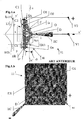
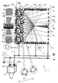
- the Figures 1.a and 1.b show schematically, in section ( figure 1.a ) and in perspective ( figure 1.b ), an electrostatic ion emission device (11) according to the prior art.
- the electrostatic ionizing device (11) according to the prior art comprises a corona conductive electrode (EC) discharge, subjected to a negative electric discharge potential (V1), emitting a global flow (I) of negative ions ( i q ). It also comprises a conductive non-corona receiving electrode (ER) subjected to a positive reception electric potential (V2).
- the receiving electrode (ER) has an active face (SA) located opposite the corona electrode (EC). It is distant from a distance (di) of its discharge zone (D) of negative ions (i q ).
- the space (H) separating the active face (SA) from the corona electrode (EC) is free.
- the receiving electrode (ER) is porous. It has a multitude of fluid passage channels (C1, C2, ..., Cn), passing through the receiving electrode (ER), and opening through a multitude of orifices (O1, O2, ..., On). , on its active face (SA), along an axis (xx ') said flow, substantially perpendicular to the active face (SA).
- a means for pressurizing the fluid ensures the movement of the fluid (F), in particular through the thickness (er) of the receiving electrode (ER), substantially in the flow axis (xx ') .
- the surface geometry of the active face (SA) is arbitrary. No particular local geometrical arrangement of the active face (SA) is provided around the orifices (O1, ...) to homogenize the flow of negative ions (i q ).
- the intensity (J (Q)) is represented along the axis (xx ').
- the ionic point surface intensity (J (Q)) has, at points Q (r) adjacent to the active surface (SA), a very inhomogeneous spatial distribution of ionic intensity (J (Q)).
- the local intensity of the ion flux Is (r) between the two electrodes (EC, ER) has been schematized by clusters of ions (i q ).
- the number of ions represented schematizes, on a radial, the intensity of the flow of ions in this direction. It can be seen that when the point (Q (r)) and its projection (P (r)) deviate from the geometric center (O), the number of ions reaching in (Q (r)) the surface (SA), and by the same the flux Is (r), decreases considerably.
- the figure 1.b schematizes in perspective the configuration of the device (11).
- FIGs 2.a and 2.b show schematically, in section ( figure 2.a ) and in perspective ( figure 2.b ), a variant of the prior art with regard to the electrostatic device (21) for ionic emission of the type of that described in the patent application US 5,474,600 on behalf of the applicants.
- the discharge electrode (EC) consists of a corona tip (22) placed at the end of a needle (23) perpendicular to the active surface (SA).
- the corona tip (22) is surrounded by a hollow metal tube (25) of small thickness (ep) of wall (26), collinear with the tip axis (x1, x'1) of the needle (23) .
- the receiving electrode (ER) is made of porous cellular metal.
- the tube (25) and the electrode (ER) are bonded and subjected to the same positive electrical potential (V2).
- the discharge corona electrode (EC) is subjected to a negative electric discharge potential (V1). It emits a global flow (I) of negative ions (i q ) in its discharge zone (D).
- This flow of ions has been schematized by means of dashed lines of variable thickness, representing its intensity in the different directions.
- the curve (27) represents the variations of the surface ionic intensity J (r) in a plane (tt ') perpendicular to the axis (xx') and intersecting the tube (25) substantially at its center.
- the ionic strength Is (r) weakens rapidly inside the tube (25) and in its central part, as a function of the distance (r) to the axis of the corona electrode (EC).
- the curve (28) also shows the variations of the ionic intensity J (r) in a plane (uu ') parallel to the active surface (SA) of the receiving electrode (ER) in the vicinity of the latter.
- the ionic strength J (r) also weakens rapidly as a function of the distance (r) to the axis (xx ') of the corona electrode (EC).
- the active surface (SA) of the receiving electrode (ER) has no particular local geometry. As is schematized figure 2.b , it can be assimilated in first approximation to a perforated plate (ER) provided with a multitude of orifices (O1, O2, ..., On) on its active face (SA) and placed at one end of the tube ( 25).
- a flow (K) of fluid (F) is shown which is penetrated into the tube (25) through the receiving electrode (ER).
- the fluid (F) is charged with a multitude of particles (p1) aerosols. These particles (p1) can be considered neutral before entering the device (21).
- the particles After passing through the receiving electrode (ER), the particles are faced with the flow of ions (i q ).
- the aerosol particles (p2) transiting close to the axis (xx ') receive a significant amount of negative ions (i q).
- Four are represented.
- the particles (p3) passing away from the axis (xx ') receive much less negative ions (i q ).
- One is represented.
- this system (21) does not significantly homogenize a flow of ions (i q ) in the vicinity of a receiving electrode (ER), nor homogenize satisfactorily the flow of ions (i q ) deposited on aerosol particles (p1, p2, p3, ...) passing right through the system (21).
- FIGS. 3a and 3b describe in section and in perspective improvements to the ion emission device (1).
- the electrostatic device (1) of ionic emission is intended to deposit on the surface (sp) of a multitude of particles (p1) aerosols within a flow (K) of fluid (F), of the same class of diameters (dp), an almost homogeneous amount of charge ions (i q ) (q).
- This electrostatic device (1) is of the type constituted by the combination between - a corona conductive electrode (EC) discharge, subjected to an electric discharge potential (V1), emitting a global flow (I) of ions (i q ) and a non-corona conductive porous receiving electrode (ER) subjected to an electric reception potential (V2).
- the receiving electrode (ER) has a pseudo plane active face (SA) located opposite the corona electrode (EC) and away from a distance (di) of its discharge zone (D).
- the free space (H) separating its active face (SA) from the tip (22) of the corona electrode (EC) is free.
- a multitude of fluid passage channels (C1, C2, ..., Cn) pass through the receiving electrode (ER). They open through a multitude of orifices (O1, O2, ..., On) of quasi-circular shape on its active face (SA), along the flux axis (xx '), substantially perpendicular to the active face ( HER). They provide, in the vicinity of the active face (SA), a fluid flow (F) along veins (not shown) passing through the receiving electrode (ER) and generally substantially parallel to said axis (xx ') of the flow (K) of fluid (F).
- the electrode (EC) corona tip (22) is surrounded by a hollow tube (25) thin (ep) wall (26).
- the hollow tube (25) is collinear with the tip axis (x1, x'1) of the needle (23), along the axis (xx ') of the fluid flow (K) (F) and located in look at the active face (SA) of the receiving electrode (ER).
- This hollow tube (25) longitudinally encompasses the fluid veins (F) opposite the active face (SA) and around the needle (23).
- the hollow tube (25) is consisting of a conductive material including metal (34).
- the hollow tube (25) is brought to the same positive electrical potential (V2) as the receiving electrode (ER) to provide electrical protection against the negative potential (V1) of the corona electrode (EC).
- the figure 13 describes additional specific details of the device (1) according to the invention.
- a means (2) for pressurizing the fluid (and in particular a fan) ensures the movement of the fluid (F) in particular through the thickness (er) of the receiving electrode (ER), substantially in said flow axis (xx '), and along said veins (not shown).
- the device (1) is equipped with an electric power source (3) comprising at least two metal terminals (B +, B-) with a relatively high electrical potential difference between them (of the order of 5000V).
- Two conductors (4,5) are each connected - at one end (6,7) to one of the potential terminals (B +, B-) and / or earth (8), - and at the other end (9).
- the electrostatic ion-emitting device (1) is provided with a particular combination of the local surface geometry of the face (SA) of the receiving electrode (ER).
- its multitude of passage channels (C1, C2, ..., Cn) of fluid (F) are positioned through the receiving electrode (ER) so that the multitude of their orifices (O1 , O2, ..., Oi, ..., On) are distributed almost uniformly on the active face (SA), in its two geometric directions (yy ', zz').
- the pseudo-plane active face (SA) of the receiving electrode (ER) is covered with a plurality of sharp points (sharp and sharp) (Ai). They emerge in relief from the active face (SA).
- the curve (32), located in the left part of the figure 3.a represents the variations of the surface ionic intensity J (r) in a plane (tt ') perpendicular to the axis (xx') and intersecting the tube (25) substantially at its center.
- the surface ionic strength J (r) weakens rapidly inside the tube (25) as a function of the distance (r) to the axis of the electrode (ER).
- the presence of spikes (sharp and sharp) (Ai) weakens the overall level of the flow of ions towards the inner wall of the tube (25) compared to what it is (see the curve (27) figure 2.a ) in the absence of sharp zones (Ai).
- the curve (33) also shows the variations of the surface ionic intensity J (r) in a plane (uu ') parallel to the active surface (SA) of the receiving electrode (ER), in the vicinity of this last.
- the surface ionic intensity J (r) on the one hand, weakens very weakly as a function of the distance (r) to the axis (xx ') of the corona electrode (EC), and, on the other hand, at an overall level higher than that which is found (such as on the curve (32), figure 2.a ) when one deviates from the receiving electrode (ER).
- the geometric arrangement described above therefore results in homogenization of the ionic flux.
- the surface ionic flux (Is (r)) of ions (i q ) coming from the corona electrode (EC) in the direction of the active pseudo plane face (SA) of the receiving electrode (ER), has an ionic surface intensity J (Q (r)) having at the points Q (r) adjacent to the active face (SA), a spatial distribution of ionic intensity J (r) with increased homogeneity, relative to the variation of spatial distance (r) between - the corresponding projection point (P (r)) of the active face (SA) of the receiving electrode (ER ), and the main ionic action zone (A) surrounding the geometric center (O) of FIG.
- the invention can be advantageously implemented with several types of corona electrodes (EC).
- the device (1) comprises the characteristic combination between: the pseudo-plane active face (SA) of the receiving electrode (ER) covered with a distributed quasi-uniformly distributed plurality of emergent sharp zones (Ai) surrounding orifices (O1, 02, ..., On) is also almost uniformly distributed, - and a discharge electrode (EC) consisting of a corona tip (22) placed at the end of a needle (23). It is oriented along a point axis (x1, x1 ') perpendicular to the face active (SA) pseudo plane, towards the emergent sharp zones (Ai), and positioned at a distance (di) opposite the active face (SA).
- SA pseudo-plane active face
- ER receiving electrode
- EC discharge electrode
- the device (1) comprises the characteristic combination between: the pseudo-plane active face (SA) of its receiving electrode (ER) covered with a distributed quasi-uniformly distributed plurality of emergent sharp zones (Ai) surrounding orifices (O1, O2) , ..., On) also quasi uniformly distributed, - and a discharge electrode (EC) consisting of a conductive wire (41), oriented along an axis (x2, x'2), substantially parallel to the active face ( SA) pseudo plane.
- the conducting wire (41) is substantially perpendicular to the emergent sharp zones (Ai), and positioned at a distance (di) facing the active face (SA).
- the invention recommends several types of geometry of emergent sharp zones (Ai).
- the pseudo-plane active face (SA) of the receiving electrode (ER) is covered with a substantially evenly distributed plurality of emergent sharp zones (Ai) in the form of spiky sharp points (42) uniformly distributed, having locally a small radius of curvature (ra) surface, surrounding orifices (O1, O2, ..., On) uniformly distributed.
- These sharp sharp points (42) point outwardly of the active face (SA) along a substantially perpendicular axis (xx ') towards the discharge zone (D).
- the pseudo-plane active face (SA) of the receiving electrode (ER) is covered by a quasi-uniformly distributed plurality of craters (43) with edges with sharp edges (Ai) closed in a pseudo-circle (44). They have on their extreme edges a section with a small radius of curvature (ra), surrounding the orifices (O1, O2, ..., On), and opening towards the outside of the active face (SA), along an axis ( xx ') substantially perpendicular to the discharge zone (D).
- the figure 13 represents the variant recommended by the invention for producing a homogenized ion emission electrostatic device (1).
- the receiving electrode (ER) is constituted by a porous structure (51). His sharply pointed and sharply sharpened zones (Ai) are distributed almost uniformly over its active face (SA) and connected to each other by means of this porous structure (51).
- the receiving electrode (ER) is constituted by a porous structure (51) with cellular mesh (52) consisting of an array of fins (Ai, an) with elongate portions (57).
- the plurality of sharp points (sharp and sharp) (Ai) distributed almost uniformly over the active face (SA) is materialized by the cutting of the honeycomb mesh structure (52) from the porous structure (51) to the right active face (SA).
- the preferred embodiment of the invention for producing a receiving electrode (ER) according to the invention appears Fig. 8 to 12 .
- the receiving electrode (ER) supporting the pseudo-plane active face (SA) is materialized using a conductive porous block (55). It consists of a porous structure (51) with cellular mesh (52) pseudo repetitive formed of a plurality of fins (..., year, ...) with elongate portions (57), constituted a conductive material (58) in particular metal.
- the fins (an) have a cross section (St) thin, of thickness (ea) much smaller than their longitudinal dimension (la). They comprise at least one elongated and tapered trailing edge (bn) (i.e., small radius (ra) transverse local curvature) oriented in the direction (xn, x'n) of the length of the fins (year).
- the fins (..., a13, a14, a15, a16, ..., an %) are physically and electrically interconnected by each of their ends (en1, en2, .%) to constitute a conductive three-dimensional network (R'xyz). They are associated and grouped geometrically to form a multiplicity of elementary cells (c1, ..., c16, c17, ...) communicating with each other to form the passage channels (C1, C2, ..., Cn) of the fluid (F).
- the fins (a13) inside the porous block (55) are mainly common to several elementary cells (..., cl, ..., c17, .
- the majority of fins (a13, a14, ...) associated belonging to the same cell (c1) inside the porous block (55) surround and adjoin tangentially, by at least one of their faces lateral longitudinal axes (s1, ....), a virtual elemental surface (62, 63) clean and internal to each elementary cell (c1, c17), of closed geometry, to encompass an empty elementary cellular volume (59, 60) picked up . That is, its transverse dimensions (dx1, dy1, dz1) are of the same order of magnitude in the three directions (x, y, z).
- the elementary empty cell volume (59) of the majority of the cells (c1) situated at the center of the porous block (55) opens out opposite the elementary empty volumes (..., 60, ...) of neighboring cells (c16, c17). , ...) by at least four (and preferably twelve) recesses (e16) through their elementary surface (62).
- Each of the recesses (e16) is surrounded by the lateral edge (b16) of fins (..., a16 ...) belonging to its cell (c16) and common to neighboring cells (..., c1, .. .).
- the figure 10 schematically describes, in a magnified manner, the surface appearance of the face (SA).
- SA active face
- the porous block (55) is cut pseudo-plane in a so-called active face (SA), thereby severing a plurality of elementary cells (cA) of the outer wall of the three-dimensional network (R'xyz), distributed uniformly on the active side (SA).
- cA elementary cells
- R'xyz three-dimensional network
- metal nozzles (71) having sharp edges (72) of substantially circular shape facing the active face (SA).
- the cells (c16, c17, ...) of the porous block (55) are positioned according to their distribution of greater density and have twelve neighboring cells. They are pierced with twelve recesses.
- the cells (c16, c17, ...) have a dodecahedral geometry.
- the preferred method for manufacturing receptor electrodes (ER) according to the invention consists in first of all producing a dielectric or semiconductor primary network.
- This primary network is geometrically identical to that of the network (R'xyz).
- the invention recommends making the receiving electrode (ER) by electrodeposition of nickel on a polyurethane primary network.
- the method consists first of all in producing a primary porous network plate of wings (an) made of polyurethane. Then an electrical conductivity is given to the primary network of polyurethane by dipping into a sensitization solution of the type: Sn Cl 1 - 25 g / l; HCl - 40 ml / l. The primary network is maintained in the solution for 10 minutes and then washed with hot water for 10 minutes. The primary network is then immersed for 5 minutes in a reservoir comprising an activation solution of the type: Pd Cl1 - 0.5 g / l HCl - 10 ml / l . Then it is washed with hot water for 10 minutes.
- a nickel chemical layer is then deposited on the primary network.
- the primary network is immersed in a solution of the type (in ml / l) : NiSO4. 7H2O - 25 NaH2PO2. H2O - 25 NaP2O7. 10H2O - 50 NH4OH (28% sol). - 23
- the primary network is maintained in the solution for 30 minutes. Then it is washed with water for 10 minutes.
- Nickel electroplating is then carried out. To do this, two nickel anodes are placed in an electrolysis bin. The primary network is placed between the two anodes in the tank. The tank is filled with a solution having a composition of the type (in g / l): NiSO 4 . 7H 2 O - 250 1.4 butandiol - 0.15 NiCl 2 - 50 phthalimide - 0.12 H 3 BO 3 - 30 PH -4.3 - 5.1
- the anodes and the primary network are connected to the different poles of a DC generator. (Anodes at the positive pole, primary network at the negative pole).
- the intensity of the deposition current is controlled at 0.5 A / dm 2 for 7-10 minutes. Ten successive deposition cycles are carried out.
- the skeleton constituted by the underlying dielectric material is extracted by a heat or chemical action on the outer metal surface of the primary network.
- a network (R'xyz) entirely metallic.
- the underlying structure of polyurethane is removed by thermal effect.
- the nickel-coated network is placed in a reducing atmosphere at a temperature of 1100 ° C. for 4 hours.
- the network (R'xyz) of the receiving electrode (ER) is then ready.
- the receiving electrode (ER) of the device (1) of the figure 13 is constituted by a porous structure (51) with cellular mesh (52) consisting of a network assembly of fins (an) with elongate portions (57).
- the plurality of sharp points (sharp and sharp) (Ai) distributed almost uniformly over the first active face (SA) are materialized by the sectioning of the alveolar mesh structure (52) of the porous structure (51). network (R'xyz) to the right of the first active face (SA).
- the plurality of sharp points (sharp and sharp) (A'i) distributed almost uniformly over the second active face (S'A) are materialized by the sectioning of the alveolar mesh structure (52) of the porous structure (51) to the right of the second face (S'A).
- the figure 14 represents an electrostatic (111) biionic emission system according to the invention for depositing on the surface (sp) of the same class of diameters (dp) of a multitude of particles (p1, p2, ...) aerosols in a fluid (F), an almost homogeneous amount for each sign, ions (i q1 ) and (i q2 ) of opposite charges.
- This bi-ionic electrostatic system (111) is typically constituted by the series-linked combination of two inverse polarity ionic electrostatic devices (101, 102) of the type (1) described above.
- the electrostatic devices (101, 102) are arranged in series along a common axis (xx ') of the fluid flow (K) (F).
- a means (2) for pressurizing the fluid common to the two devices (1,1 ') ensures the movement of the fluid (F) in particular through the receiving electrode (ER1) of the device (101) and (ER2) of the device (102), substantially in the common axis (xx ') of the fluid flow (K) (F).
- the system (111) comprises three non-corona conducting electrodes (ER1, ER2, ER3) located in series, and brought to alternating electrical potentials (V21, V22, V23). They were made according to the manufacturing method described above. They have the geometry shown figure 8 to 12 . They each have two pseudo-plane lateral faces substantially parallel: a first face (SA1, SA2, SA3), and a second face (S'A1, S'A2, S'A3).
- the system comprise at least two corona conductive electrodes (EC1, EC2) with discharge, subjected to an alternating electric discharge potential (V11, V12), emitting an overall flow (I1) of ions (i q1 ), and (I2) ions (i q2 ) of opposite signs.
- the first corona electrode (EC1) is placed between the first pair of receptor electrodes (ER1, ER2).
- Its discharge zone (D1) is located opposite the active face (SA1) of one (ER1) of the two receiver electrodes (ER1, ER2) of the first pair.
- the second electrode corona (EC2) is placed between the second pair of receiving electrodes (ER2, ER3).
- Its discharge zone (D2) is located opposite the active face (SA2) of one (ER2) of the two receiving electrodes (ER2, ER3) of the second pair.
- the two faces (SA2, S'A2) pseudo-planes of the central receiving electrode (ER2) are each covered with a plurality of sharply pointed zones (sharp and sharp) (A2, A'2). , emerging in relief one (A2) of the first (SA2), and the others (A'2) of the second active face (SA'2). They present locally a small radius of curvature (ra) surface. They are distributed almost uniformly in both directions (yy ', zz'). On the first face (SA2) they surround the corresponding (Oni) orifices. On the second face (S'A2) they surround the corresponding holes (O'ni). In fact the three receiving electrodes of the system (111) shown figure 14 are identical and have their 2 sides similar by construction.
- the electrostatic system (131) has two stages (121, 122) of ionic emission, arranged in series. Each stage (121, 122) is constituted by the characteristic parallel combination of a plurality of electrostatic devices. (123,124,125), (126,127,128) ionic emission of type (1) described above.
- the electrostatic devices (123,124,125) of the same stage (121) are arranged side by side transversely to the axis (xx ') overall of the fluid flow (F).
- Signs of polarity of the pairs (V1, V'1, V "1) and (V2, V'2, V” 2) of the same stage (121), corresponding: - to the electric potential of the corona conductive electrodes, and to the electric potential of the non-corona conductive receiving electrodes, of each of the two electrostatic devices (123, 124, 125) are similar.
- the receiving electrodes (ER1, ER'1, ER "1) of the electrostatic devices (123,124,125) constituting it are produced by a common porous plate (64) constituted by a network (R'xyz) of fins (an) of the type described higher, located transversely to the axis (xx ') of flow (F).
- the overall flow of negative ions (i q2 ) encountered in the veins of passages of the flow (F), at the crossing of the device (102) along the axis (xx ') of flow, is almost homogeneous throughout the section of its tube (25).
- the particles (p3) previously loaded in a substantially homogeneous manner with positive ions (i q1 ) are also loaded with an almost homogeneous amount of negative ions (i q1 ).
- Four positive ions (i q1 ) and four negative ions (i q2 ) are represented on the particles (p3).
- the particles (p3) are covered with a homogeneous amount of ions of opposite signs (i q1 , i q2 ).
- the inventors have experimentally found that the combination of the bi-ionic system (111) according to the invention results in a homogeneity (expressed in terms of standard deviation) of the deposits of positive ions (i q1 ) and of negative ions (i q2 ). on particles (p3), which they measured to be about + -10%. This was measured with devices (101,102) of 5 cm tube diameter, each equipped with a tip corona 2.5 cm distant from the receiving electrode and subject to a potential difference of + - 5000V. The experiment was carried out on particle size classes ranging from 0.01 micron to 3 microns. When the same experiment was carried out with ionic emission devices of equivalent size according to the prior art, the homogeneity of ionic deposition (expressed in terms of standard deviation) was about + -80% under the same conditions.
- the devices (1) according to the invention make it possible to homogenize the ion flux opposite the active plane face of a receiving electrode (ER).
- the devices (1) according to the invention make it possible to subject a multitude of particles (such as: dust, bio-aerosols or specific molecules, etc.) aerosols within a fluid in motion, to the action of an ion flux coming from the corona discharge electrode (CE), whose overall intensity inside any flow vein located inside the tube (25) is almost homogeneous at the crossing of tube.
- particles such as: dust, bio-aerosols or specific molecules, etc.
- the devices (1) according to the invention make it possible to deposit on the surface of this multitude of aerosol particles (belonging to the same class of diameters) an almost homogeneous quantity of ions (i q ).
- the devices (1) according to the invention make it possible to increase the efficiency of the flow of ions (i q ) in the direction of the electrode (ER) and thus in the direction of the flow veins, by reducing the less efficient and inhomogeneous radial flow in the direction of the wall (26) of the tube (25).
- the bi-ionic systems (111) according to the invention make it possible to deposit a homogeneous quantity of ions of opposite sign (i q1 , i q2 ) on the surface of the particles.
- the invention has industrial applications in many fields, including physical, chemical, energy, biological where it is appropriate to depositing on a aerosol particles a homogeneous amount of ions, with a view to inflicting a controlled and almost uniform physical effect.
Landscapes
- Chemical & Material Sciences (AREA)
- Health & Medical Sciences (AREA)
- General Health & Medical Sciences (AREA)
- Toxicology (AREA)
- Organic Chemistry (AREA)
- Chemical Kinetics & Catalysis (AREA)
- Electrostatic Separation (AREA)
- Physical Or Chemical Processes And Apparatus (AREA)
- Electrostatic Spraying Apparatus (AREA)
- Cleaning In General (AREA)
- Respiratory Apparatuses And Protective Means (AREA)
- Electron Sources, Ion Sources (AREA)
- Gas Separation By Absorption (AREA)
- Disinfection, Sterilisation Or Deodorisation Of Air (AREA)
Claims (7)
- lonen-Emissionsvorrichtung, eine Korona-Entladungselektrode (EC) zur Emission von Ionen aufweisend, dadurch gekennzeichnet, dass sie eine poröse, metallische Empfangselektrode (ER) umfasst, die eine offenzellige Metallschaumstruktur und eine im Wesentlichen ebene aktive Oberfläche (SA) aufweist, die der Entladungselektrode zugewandt ist, wobei die aktive Oberfläche eine Vielzahl im Wesentlichen spitzer Punkte (AI) aufweist.
- lonen-Emissionsvorrichtung nach Patentanspruch 1, in der die Empfangselektrode (ER) durch Galvanostegie eines metallischen Werkstoffs (58) auf ein dielektrisches Grundgitter aus einem Polyurethanwerkstoff ausgebildet wird.
- lonen-Emissionsvorrichtung nach Patentanspruch 1 oder 2, in der die spitzen Punkte (AI) quasi-gleichförmig über die aktive Oberfläche der Empfangselektrode (ER) verteilt sind.
- lonen-Emissionsvorrichtung nach irgendeinem der vorangehenden Patentansprüche, außerdem eine Leistungsspannungsversorgung (3) umfassend, geeignet, ein erstes Potential an die Empfangselektrode (ER) und ein zweites Potential an die Korona-Entladungselektrode (EC) anzulegen, wobei die Potentialdifferenz zwischen dem ersten und dem zweiten Potential mindestens ungefähr 5000 Volt beträgt.
- lonen-Emissionsvorrichtung nach irgendeinem der vorangehenden Patentansprüche, in der die Korona-Entladungselektrode (EC) eine lonisationselektrode vom Nadeltyp (23) mit einer Achse (x1, x1') umfasst, die im Wesentlichen senkrecht auf der aktiven Oberfläche der Empfangselektrode steht.
- lonen-Emissionsvorrichtung nach irgendeinem der vorangehenden Patentansprüche, außerdem eine Elektrodenkammer (25) umfassend, die mit der Korona-Entladungselektrode (EC) axial ausgerichtet ist, derart dass eine Achse der Elektrodenkammer im Wesentlichen senkrecht auf der aktiven Oberfläche der Empfangselektrode (ER) steht.
- lonen-Emissionsvorrichtung nach Patentanspruch 6, in der die Leistungsspannungsversorgung (3) außerdem geeignet ist, das erste Potential an die Elektrodenkammer anzulegen, derart dass die Elektrodenkammer und die Empfangselektrode auf demselben Spannungspotential gehalten werden.
Priority Applications (1)
| Application Number | Priority Date | Filing Date | Title |
|---|---|---|---|
| EP07002603.4A EP2018909B1 (de) | 2000-12-18 | 2001-12-17 | Vorrichtung zur ionischen Emission |
Applications Claiming Priority (3)
| Application Number | Priority Date | Filing Date | Title |
|---|---|---|---|
| FR0016607A FR2818451B1 (fr) | 2000-12-18 | 2000-12-18 | Dispositif electrostatique d'emission ionique pour deposer une quantite quasi homogene d'ions sur la surface d'une multitude de particules aerosols au sein d'un fluide en mouvement. |
| EP07002603.4A EP2018909B1 (de) | 2000-12-18 | 2001-12-17 | Vorrichtung zur ionischen Emission |
| EP01994883A EP1455947B1 (de) | 2000-12-18 | 2001-12-17 | Elektrostatische vorrichtung zur ionischen luftemission |
Related Parent Applications (1)
| Application Number | Title | Priority Date | Filing Date |
|---|---|---|---|
| EP01994883A Division EP1455947B1 (de) | 2000-12-18 | 2001-12-17 | Elektrostatische vorrichtung zur ionischen luftemission |
Publications (2)
| Publication Number | Publication Date |
|---|---|
| EP2018909A1 EP2018909A1 (de) | 2009-01-28 |
| EP2018909B1 true EP2018909B1 (de) | 2017-09-13 |
Family
ID=8857889
Family Applications (2)
| Application Number | Title | Priority Date | Filing Date |
|---|---|---|---|
| EP07002603.4A Expired - Lifetime EP2018909B1 (de) | 2000-12-18 | 2001-12-17 | Vorrichtung zur ionischen Emission |
| EP01994883A Expired - Lifetime EP1455947B1 (de) | 2000-12-18 | 2001-12-17 | Elektrostatische vorrichtung zur ionischen luftemission |
Family Applications After (1)
| Application Number | Title | Priority Date | Filing Date |
|---|---|---|---|
| EP01994883A Expired - Lifetime EP1455947B1 (de) | 2000-12-18 | 2001-12-17 | Elektrostatische vorrichtung zur ionischen luftemission |
Country Status (14)
| Country | Link |
|---|---|
| US (2) | US7198660B2 (de) |
| EP (2) | EP2018909B1 (de) |
| JP (1) | JP4220238B2 (de) |
| CN (1) | CN1268437C (de) |
| AT (1) | ATE412468T1 (de) |
| AU (1) | AU2002225086A1 (de) |
| BR (1) | BR0116851B1 (de) |
| CA (1) | CA2432040C (de) |
| DE (1) | DE60136394D1 (de) |
| ES (1) | ES2314001T3 (de) |
| FR (1) | FR2818451B1 (de) |
| MX (1) | MXPA03005103A (de) |
| RU (1) | RU2265485C2 (de) |
| WO (1) | WO2002049767A1 (de) |
Families Citing this family (31)
| Publication number | Priority date | Publication date | Assignee | Title |
|---|---|---|---|---|
| US7029636B2 (en) | 1999-12-15 | 2006-04-18 | Plasmasol Corporation | Electrode discharge, non-thermal plasma device (reactor) for the pre-treatment of combustion air |
| US7094322B1 (en) | 1999-12-15 | 2006-08-22 | Plasmasol Corporation Wall Township | Use of self-sustained atmospheric pressure plasma for the scattering and absorption of electromagnetic radiation |
| US6955794B2 (en) | 1999-12-15 | 2005-10-18 | Plasmasol Corporation | Slot discharge non-thermal plasma apparatus and process for promoting chemical reaction |
| US7192553B2 (en) | 1999-12-15 | 2007-03-20 | Plasmasol Corporation | In situ sterilization and decontamination system using a non-thermal plasma discharge |
| FR2818451B1 (fr) * | 2000-12-18 | 2007-04-20 | Jean Marie Billiotte | Dispositif electrostatique d'emission ionique pour deposer une quantite quasi homogene d'ions sur la surface d'une multitude de particules aerosols au sein d'un fluide en mouvement. |
| EP1430501A2 (de) | 2001-07-02 | 2004-06-23 | Plasmasol Corporation | Neuartige elektrode zur verwendung mit einer atmosphärendruck-plasmaemittervorrichtung und verfahren zu ihrer verwendung |
| US7553353B2 (en) | 2004-02-11 | 2009-06-30 | Jean-Pierre Lepage | System for treating contaminated gas |
| US7452410B2 (en) | 2005-12-17 | 2008-11-18 | Airinspace B.V. | Electrostatic filter having insulated electrodes |
| US7279028B2 (en) * | 2005-12-17 | 2007-10-09 | Airinspace B.V. | Electrostatic filter |
| JP2009519819A (ja) | 2005-12-17 | 2009-05-21 | エアーインスペース・ビー.ブイ. | 空気浄化装置 |
| US7384456B2 (en) * | 2006-05-15 | 2008-06-10 | Airinspace B.V. | Modular frame for air purification devices |
| ES2562446T3 (es) * | 2008-09-18 | 2016-03-04 | Nagolkin, Alexandr Vladimirovich | Dispositivo de inactivación y de filtración fina de virus y microorganismos en un flujo de aire |
| RU2453376C2 (ru) * | 2009-03-06 | 2012-06-20 | Александр Владимирович Стегленко | Газоразрядный блок установки для очистки газов |
| CN201438807U (zh) * | 2009-06-29 | 2010-04-14 | 国琏电子(上海)有限公司 | 离子散热装置及系统 |
| US8973851B2 (en) * | 2009-07-01 | 2015-03-10 | The Procter & Gamble Company | Apparatus and methods for producing charged fluid droplets |
| US20110116206A1 (en) * | 2009-11-16 | 2011-05-19 | Mentornics, Inc. | Cooling of electronic components using self-propelled ionic wind |
| US9013316B2 (en) * | 2011-07-28 | 2015-04-21 | Finsecur | Smoke detector |
| US9488382B2 (en) | 2012-05-15 | 2016-11-08 | University Of Washington Through Its Center For Commercialization | Electronic air cleaners and associated systems and methods |
| EP2772309B1 (de) | 2013-03-01 | 2015-06-03 | Brandenburgische Technische Universität Cottbus-Senftenberg | Vorrichtung zum Abscheiden von Partikeln aus einem mit Partikeln beladenen Gasstrom und Verfahren |
| US9682345B2 (en) | 2014-07-08 | 2017-06-20 | Particle Measuring Systems, Inc. | Method of treating a cleanroom enclosure |
| US9827573B2 (en) | 2014-09-11 | 2017-11-28 | University Of Washington | Electrostatic precipitator |
| WO2016147127A1 (de) * | 2015-03-19 | 2016-09-22 | Woco Industrietechnik Gmbh | Vorrichtung und verfahren zum abscheiden von verunreinigungen |
| CN106237780A (zh) * | 2016-08-26 | 2016-12-21 | 中国石油天然气股份有限公司 | 注汽锅炉除尘装置和注汽锅炉 |
| RU170188U1 (ru) * | 2017-01-09 | 2017-04-18 | Федеральное государственное бюджетное образовательное учреждение высшего образования "Казанский государственный энергетический университет" | Устройство очистки газовых сред |
| CN106949824B (zh) * | 2017-04-17 | 2023-04-07 | 中水东北勘测设计研究有限责任公司 | 水下淤泥爆破空腔半径电极阵列测试法 |
| US11291102B2 (en) | 2017-04-20 | 2022-03-29 | Airinspace S.E. | Corona effect plasma device and plasma reactor |
| FR3087677B1 (fr) | 2018-10-25 | 2022-12-16 | Airinspace | Nouveau dispositif d’epuration d’air par plasma |
| FR3065615B1 (fr) * | 2017-04-20 | 2022-12-16 | Airinspace | Dispositif plasma a effet corona et reacteur plasma |
| CN108318848B (zh) * | 2018-02-13 | 2020-09-22 | 北京无线电计量测试研究所 | 一种沉积静电放电电流的校准装置和方法 |
| US10938188B2 (en) * | 2018-04-02 | 2021-03-02 | Igistec Co., Ltd. | Ion wind generating device |
| CN114673641B (zh) * | 2020-12-25 | 2024-07-09 | 海鹰航空通用装备有限责任公司 | 一种离子推进装置 |
Family Cites Families (43)
| Publication number | Priority date | Publication date | Assignee | Title |
|---|---|---|---|---|
| BE368865A (de) * | ||||
| US1767338A (en) * | 1927-05-27 | 1930-06-24 | Int Precipitation Co | Electrical precipitating apparatus |
| US4056372A (en) * | 1971-12-29 | 1977-11-01 | Nafco Giken, Ltd. | Electrostatic precipitator |
| US4066526A (en) * | 1974-08-19 | 1978-01-03 | Yeh George C | Method and apparatus for electrostatic separating dispersed matter from a fluid medium |
| US4910637A (en) * | 1978-10-23 | 1990-03-20 | Rinoud Hanna | Modifying the discharge breakdown |
| US4313739A (en) * | 1979-10-01 | 1982-02-02 | Avco Everett Research Laboratory, Inc. | Removal of contaminants from gases |
| US4597781A (en) * | 1984-11-21 | 1986-07-01 | Donald Spector | Compact air purifier unit |
| ATE40302T1 (de) * | 1984-12-21 | 1989-02-15 | Bbc Brown Boveri & Cie | Verfahren und vorrichtung zur entstaubung eines feste oder fluessige partikel in suspension enthaltenden gasstromes mittels eines elektrischen feldes. |
| NL8701660A (nl) * | 1987-07-14 | 1989-02-01 | Tno | Verbrandingsinrichting met een gefluidiseerd bed. |
| DE3723544A1 (de) * | 1987-07-16 | 1989-01-26 | Man Technologie Gmbh | Elektrostatischer filter zum reinigen von gasen |
| US4904283A (en) * | 1987-11-24 | 1990-02-27 | Government Of The United States As Represented By Administrator Environmental Protection Agency | Enhanced fabric filtration through controlled electrostatically augmented dust deposition |
| US4979364A (en) * | 1988-03-11 | 1990-12-25 | Fleck Carl M | Diesel fuel exhaust gas filter |
| JPH02172545A (ja) * | 1988-12-23 | 1990-07-04 | Hiroaki Kanazawa | 空気清浄機 |
| US4920266A (en) * | 1989-03-27 | 1990-04-24 | Xerox Corporation | Corona generating device |
| US5055155A (en) * | 1989-10-12 | 1991-10-08 | Texstyle, Inc. | Method and apparatus for laminating flexible magnetic strips onto flexible plastic substrates |
| EP0425433A1 (de) * | 1989-10-26 | 1991-05-02 | Alusuisse-Lonza Services Ag | Filtermaterial für die Ausfiltrierung von Russpartikeln |
| AU647491B2 (en) * | 1990-07-02 | 1994-03-24 | Carl M. Fleck | Process and device for cleaning exhaust gases |
| JPH04110013A (ja) * | 1990-08-30 | 1992-04-10 | Meidensha Corp | 排気ガス処理装置 |
| RU2026751C1 (ru) * | 1992-05-13 | 1995-01-20 | Елена Владимировна Володина | Устройство для стерилизации и тонкой фильтрации газа |
| KR950000197A (ko) * | 1993-06-02 | 1995-01-03 | 히데오 요시카와 | 오염공기용 정화장치 |
| GB2279892A (en) * | 1993-07-17 | 1995-01-18 | Robert William Gibbs | Electrostatic filter |
| DE4400827C1 (de) * | 1994-01-13 | 1995-04-20 | Andreas Dipl Ing Gutsch | Verfahren und Vorrichtung zur elektrisch induzierten Agglomeration gasgetragener Partikeln |
| US5922111A (en) * | 1994-08-30 | 1999-07-13 | Omi Kogyo Co., Ltd. | Electrostatic precipitator |
| JPH08131884A (ja) | 1994-09-13 | 1996-05-28 | Masaaki Uehara | コロナ放電を利用した空気流発生装置 |
| US5622543A (en) * | 1995-09-20 | 1997-04-22 | Yang; Chen-Ho | Rectilinear turbulent flow type air purifier |
| US5733360A (en) * | 1996-04-05 | 1998-03-31 | Environmental Elements Corp. | Corona discharge reactor and method of chemically activating constituents thereby |
| US5695549A (en) * | 1996-04-05 | 1997-12-09 | Environmental Elements Corp. | System for removing fine particulates from a gas stream |
| JP2733908B2 (ja) * | 1996-04-23 | 1998-03-30 | 株式会社オーデン | 電気集塵ユニット及びその製造方法、並びに、該ユニットを用いる空気清浄機、電気集塵装置及び黒煙捕集装置 |
| GB9615859D0 (en) * | 1996-07-29 | 1996-09-11 | Boc Group Plc | Processes and apparatus for the scrubbing of exhaust gas streams |
| US5667564A (en) * | 1996-08-14 | 1997-09-16 | Wein Products, Inc. | Portable personal corona discharge device for destruction of airborne microbes and chemical toxins |
| DE19651402A1 (de) * | 1996-12-11 | 1998-06-18 | T E M Tech Entwicklung Und Man | Apparat zur physikalischen Aufbereitung von Luft, insbesondere von Atemluft |
| CN1223174A (zh) * | 1998-01-16 | 1999-07-21 | 俞其进 | 电子集尘式空气净化器 |
| JP3046951B2 (ja) * | 1998-04-27 | 2000-05-29 | 株式会社セイスイ | 空気清浄化装置 |
| US6228149B1 (en) * | 1999-01-20 | 2001-05-08 | Patterson Technique, Inc. | Method and apparatus for moving, filtering and ionizing air |
| US6126727A (en) * | 1999-01-28 | 2000-10-03 | Lo; Ching-Hsiang | Electrode panel-drawing device of a static ion discharger |
| US6312507B1 (en) * | 1999-02-12 | 2001-11-06 | Sharper Image Corporation | Electro-kinetic ionic air refreshener-conditioner for pet shelter and litter box |
| JP3287468B2 (ja) * | 1999-11-15 | 2002-06-04 | 株式会社オーデン | 電気集塵ユニット |
| FR2801443B1 (fr) * | 1999-11-23 | 2004-08-27 | Elena Vladimirona Volodina | Dispositif pour soumettre un fluide charge de particules aerosol a l'action d'un champ electrostatique a fortes variations d'amplitude et d'orientation et procede de fabrication |
| US6585803B1 (en) * | 2000-05-11 | 2003-07-01 | University Of Southern California | Electrically enhanced electrostatic precipitator with grounded stainless steel collector electrode and method of using same |
| JP2002059027A (ja) | 2000-08-23 | 2002-02-26 | Mitsubishi Electric Corp | 空気浄化装置 |
| FR2818451B1 (fr) * | 2000-12-18 | 2007-04-20 | Jean Marie Billiotte | Dispositif electrostatique d'emission ionique pour deposer une quantite quasi homogene d'ions sur la surface d'une multitude de particules aerosols au sein d'un fluide en mouvement. |
| US6620224B1 (en) * | 2002-08-12 | 2003-09-16 | Kabushiki Kaisha Circland | Air purification device with a needle-shaped electrode having a protective cover thereon |
| US7279028B2 (en) * | 2005-12-17 | 2007-10-09 | Airinspace B.V. | Electrostatic filter |
-
2000
- 2000-12-18 FR FR0016607A patent/FR2818451B1/fr not_active Expired - Fee Related
-
2001
- 2001-12-17 EP EP07002603.4A patent/EP2018909B1/de not_active Expired - Lifetime
- 2001-12-17 EP EP01994883A patent/EP1455947B1/de not_active Expired - Lifetime
- 2001-12-17 ES ES01994883T patent/ES2314001T3/es not_active Expired - Lifetime
- 2001-12-17 AT AT01994883T patent/ATE412468T1/de not_active IP Right Cessation
- 2001-12-17 MX MXPA03005103A patent/MXPA03005103A/es not_active Application Discontinuation
- 2001-12-17 DE DE60136394T patent/DE60136394D1/de not_active Expired - Lifetime
- 2001-12-17 AU AU2002225086A patent/AU2002225086A1/en not_active Abandoned
- 2001-12-17 US US10/450,565 patent/US7198660B2/en not_active Expired - Lifetime
- 2001-12-17 CN CNB018231934A patent/CN1268437C/zh not_active Expired - Fee Related
- 2001-12-17 WO PCT/FR2001/004019 patent/WO2002049767A1/fr not_active Ceased
- 2001-12-17 CA CA2432040A patent/CA2432040C/en not_active Expired - Fee Related
- 2001-12-17 JP JP2002551097A patent/JP4220238B2/ja not_active Expired - Fee Related
- 2001-12-17 RU RU2003116904/12A patent/RU2265485C2/ru not_active IP Right Cessation
- 2001-12-17 BR BRPI0116851-7A patent/BR0116851B1/pt not_active IP Right Cessation
-
2006
- 2006-12-19 US US11/642,278 patent/US7452411B2/en not_active Expired - Fee Related
Non-Patent Citations (1)
| Title |
|---|
| None * |
Also Published As
| Publication number | Publication date |
|---|---|
| FR2818451B1 (fr) | 2007-04-20 |
| RU2265485C2 (ru) | 2005-12-10 |
| EP1455947B1 (de) | 2008-10-29 |
| EP1455947A1 (de) | 2004-09-15 |
| ES2314001T3 (es) | 2009-03-16 |
| MXPA03005103A (es) | 2005-02-17 |
| JP2005537910A (ja) | 2005-12-15 |
| US7452411B2 (en) | 2008-11-18 |
| WO2002049767A1 (fr) | 2002-06-27 |
| US7198660B2 (en) | 2007-04-03 |
| BR0116851B1 (pt) | 2014-08-05 |
| US20050098040A1 (en) | 2005-05-12 |
| EP2018909A1 (de) | 2009-01-28 |
| ATE412468T1 (de) | 2008-11-15 |
| FR2818451A1 (fr) | 2002-06-21 |
| CN1268437C (zh) | 2006-08-09 |
| AU2002225086A1 (en) | 2002-07-01 |
| CA2432040A1 (en) | 2002-06-27 |
| US20070256563A1 (en) | 2007-11-08 |
| DE60136394D1 (de) | 2008-12-11 |
| BR0116851A (pt) | 2004-02-25 |
| CN1529636A (zh) | 2004-09-15 |
| JP4220238B2 (ja) | 2009-02-04 |
| CA2432040C (en) | 2010-07-06 |
Similar Documents
| Publication | Publication Date | Title |
|---|---|---|
| EP2018909B1 (de) | Vorrichtung zur ionischen Emission | |
| WO2001038000A1 (fr) | Traitement electrostatique d'aerosols, dispositifs et procede de fabrication | |
| EP1919626B1 (de) | Vorrichtung zur luft-/wasser-extraktion durch halbfeuchtes elektrostatisches auffangen und verwendungsverfahren dafür | |
| EP2564933B1 (de) | Elektrostatische Sammelvorrichtung von Partikeln suspendiert in einem gasförmigen Medium | |
| FR3065615A1 (fr) | Dispositif plasma a effet corona et reacteur plasma | |
| EP3328548A1 (de) | Verfahren und vorrichtung zum sammeln selektiver aerosolpartikel nach partikelgrösse | |
| FR2989905A1 (fr) | Dispositif electrostatique de collecte de particules en suspension dans un milieu gazeux | |
| FR2831084A1 (fr) | Procede et systeme pour manipuler par dielectrophorese des particules dielectriques, en particulier des cellules biologiques | |
| EP3870342A1 (de) | Neuartige vorrichtung zur reinigung von luft mittels plasma | |
| EP1738817A1 (de) | Vorrichtung zur Gasbehandlung durch Katalyse, insbesondere für eine Abzugshaube | |
| KR100701400B1 (ko) | 오일 미스트 제거를 위한 저온플라즈마 예비 하전 장치 | |
| CN113330195B (zh) | 一种发动机进气除尘系统及方法 | |
| US7776140B2 (en) | Device for removing soot particles from an exhaust gas stream | |
| FR2623424A1 (fr) | Dispositif et procede de filtrage electrostatique a filtre perpendiculaire a l'ecoulement de fluide gazeux, notamment de l'air | |
| EP1674160B1 (de) | Partikelfilter zur Abgasnachbehandlung eines Verbrennungsmotors eines Kraftfahrzeuges und entsprechendes Verfahren zur Filtrierung von Abgaspartikeln | |
| Deputatova et al. | Confinement of charged microparticles in a gas flow by the linear Paul trap | |
| EP4587190A1 (de) | Filtrationssystem mit sehr hohem wirkungsgrad mit einem vorfilter und einem dem vorfilter nachgeschalteten elektrostatischen abscheider/kollektor | |
| EP4285941A1 (de) | Ionenvorrichtung zur luftbehandlung | |
| Li et al. | Electrostatic Deposition of Fine Particles for Fabrication of Porous Ceramic Filter | |
| EP0101354A1 (de) | Entstaubungsanordnung für Staub enthaltendes Gas | |
| BE517816A (de) | ||
| BE500292A (de) | ||
| FR2477328A1 (fr) | Appareil de decharge par effluve par ionisation | |
| BE571344A (de) |
Legal Events
| Date | Code | Title | Description |
|---|---|---|---|
| PUAI | Public reference made under article 153(3) epc to a published international application that has entered the european phase |
Free format text: ORIGINAL CODE: 0009012 |
|
| 17P | Request for examination filed |
Effective date: 20070207 |
|
| AC | Divisional application: reference to earlier application |
Ref document number: 1455947 Country of ref document: EP Kind code of ref document: P |
|
| AK | Designated contracting states |
Kind code of ref document: A1 Designated state(s): AT BE CH CY DE DK ES FI FR GB GR IE IT LI LU MC NL PT SE TR |
|
| 17Q | First examination report despatched |
Effective date: 20090506 |
|
| AKX | Designation fees paid |
Designated state(s): AT BE CH CY DE DK ES FI FR GB GR IE IT LI LU MC NL PT SE TR |
|
| GRAP | Despatch of communication of intention to grant a patent |
Free format text: ORIGINAL CODE: EPIDOSNIGR1 |
|
| INTG | Intention to grant announced |
Effective date: 20170329 |
|
| GRAS | Grant fee paid |
Free format text: ORIGINAL CODE: EPIDOSNIGR3 |
|
| GRAA | (expected) grant |
Free format text: ORIGINAL CODE: 0009210 |
|
| AC | Divisional application: reference to earlier application |
Ref document number: 1455947 Country of ref document: EP Kind code of ref document: P |
|
| AK | Designated contracting states |
Kind code of ref document: B1 Designated state(s): AT BE CH CY DE DK ES FI FR GB GR IE IT LI LU MC NL PT SE TR |
|
| REG | Reference to a national code |
Ref country code: GB Ref legal event code: FG4D Free format text: NOT ENGLISH |
|
| REG | Reference to a national code |
Ref country code: CH Ref legal event code: EP |
|
| REG | Reference to a national code |
Ref country code: IE Ref legal event code: FG4D Free format text: LANGUAGE OF EP DOCUMENT: FRENCH |
|
| REG | Reference to a national code |
Ref country code: AT Ref legal event code: REF Ref document number: 927612 Country of ref document: AT Kind code of ref document: T Effective date: 20171015 |
|
| REG | Reference to a national code |
Ref country code: DE Ref legal event code: R096 Ref document number: 60150595 Country of ref document: DE |
|
| REG | Reference to a national code |
Ref country code: FR Ref legal event code: PLFP Year of fee payment: 17 |
|
| REG | Reference to a national code |
Ref country code: NL Ref legal event code: MP Effective date: 20170913 |
|
| PG25 | Lapsed in a contracting state [announced via postgrant information from national office to epo] |
Ref country code: SE Free format text: LAPSE BECAUSE OF FAILURE TO SUBMIT A TRANSLATION OF THE DESCRIPTION OR TO PAY THE FEE WITHIN THE PRESCRIBED TIME-LIMIT Effective date: 20170913 Ref country code: FI Free format text: LAPSE BECAUSE OF FAILURE TO SUBMIT A TRANSLATION OF THE DESCRIPTION OR TO PAY THE FEE WITHIN THE PRESCRIBED TIME-LIMIT Effective date: 20170913 |
|
| REG | Reference to a national code |
Ref country code: AT Ref legal event code: MK05 Ref document number: 927612 Country of ref document: AT Kind code of ref document: T Effective date: 20170913 |
|
| PG25 | Lapsed in a contracting state [announced via postgrant information from national office to epo] |
Ref country code: GR Free format text: LAPSE BECAUSE OF FAILURE TO SUBMIT A TRANSLATION OF THE DESCRIPTION OR TO PAY THE FEE WITHIN THE PRESCRIBED TIME-LIMIT Effective date: 20171214 Ref country code: ES Free format text: LAPSE BECAUSE OF FAILURE TO SUBMIT A TRANSLATION OF THE DESCRIPTION OR TO PAY THE FEE WITHIN THE PRESCRIBED TIME-LIMIT Effective date: 20170913 |
|
| PG25 | Lapsed in a contracting state [announced via postgrant information from national office to epo] |
Ref country code: NL Free format text: LAPSE BECAUSE OF FAILURE TO SUBMIT A TRANSLATION OF THE DESCRIPTION OR TO PAY THE FEE WITHIN THE PRESCRIBED TIME-LIMIT Effective date: 20170913 |
|
| PG25 | Lapsed in a contracting state [announced via postgrant information from national office to epo] |
Ref country code: AT Free format text: LAPSE BECAUSE OF FAILURE TO SUBMIT A TRANSLATION OF THE DESCRIPTION OR TO PAY THE FEE WITHIN THE PRESCRIBED TIME-LIMIT Effective date: 20170913 Ref country code: IT Free format text: LAPSE BECAUSE OF FAILURE TO SUBMIT A TRANSLATION OF THE DESCRIPTION OR TO PAY THE FEE WITHIN THE PRESCRIBED TIME-LIMIT Effective date: 20170913 |
|
| REG | Reference to a national code |
Ref country code: DE Ref legal event code: R097 Ref document number: 60150595 Country of ref document: DE |
|
| PLBE | No opposition filed within time limit |
Free format text: ORIGINAL CODE: 0009261 |
|
| STAA | Information on the status of an ep patent application or granted ep patent |
Free format text: STATUS: NO OPPOSITION FILED WITHIN TIME LIMIT |
|
| PG25 | Lapsed in a contracting state [announced via postgrant information from national office to epo] |
Ref country code: DK Free format text: LAPSE BECAUSE OF FAILURE TO SUBMIT A TRANSLATION OF THE DESCRIPTION OR TO PAY THE FEE WITHIN THE PRESCRIBED TIME-LIMIT Effective date: 20170913 |
|
| REG | Reference to a national code |
Ref country code: CH Ref legal event code: PL |
|
| 26N | No opposition filed |
Effective date: 20180614 |
|
| REG | Reference to a national code |
Ref country code: IE Ref legal event code: MM4A Ref country code: FR Ref legal event code: PLFP Year of fee payment: 18 |
|
| PG25 | Lapsed in a contracting state [announced via postgrant information from national office to epo] |
Ref country code: LU Free format text: LAPSE BECAUSE OF NON-PAYMENT OF DUE FEES Effective date: 20171217 |
|
| REG | Reference to a national code |
Ref country code: BE Ref legal event code: MM Effective date: 20171231 |
|
| PG25 | Lapsed in a contracting state [announced via postgrant information from national office to epo] |
Ref country code: IE Free format text: LAPSE BECAUSE OF NON-PAYMENT OF DUE FEES Effective date: 20171217 |
|
| PG25 | Lapsed in a contracting state [announced via postgrant information from national office to epo] |
Ref country code: LI Free format text: LAPSE BECAUSE OF NON-PAYMENT OF DUE FEES Effective date: 20171231 Ref country code: CH Free format text: LAPSE BECAUSE OF NON-PAYMENT OF DUE FEES Effective date: 20171231 Ref country code: BE Free format text: LAPSE BECAUSE OF NON-PAYMENT OF DUE FEES Effective date: 20171231 |
|
| PG25 | Lapsed in a contracting state [announced via postgrant information from national office to epo] |
Ref country code: MC Free format text: LAPSE BECAUSE OF FAILURE TO SUBMIT A TRANSLATION OF THE DESCRIPTION OR TO PAY THE FEE WITHIN THE PRESCRIBED TIME-LIMIT Effective date: 20170913 |
|
| PG25 | Lapsed in a contracting state [announced via postgrant information from national office to epo] |
Ref country code: CY Free format text: LAPSE BECAUSE OF NON-PAYMENT OF DUE FEES Effective date: 20170913 |
|
| PGFP | Annual fee paid to national office [announced via postgrant information from national office to epo] |
Ref country code: DE Payment date: 20191203 Year of fee payment: 19 |
|
| PGFP | Annual fee paid to national office [announced via postgrant information from national office to epo] |
Ref country code: FR Payment date: 20191107 Year of fee payment: 19 |
|
| PG25 | Lapsed in a contracting state [announced via postgrant information from national office to epo] |
Ref country code: TR Free format text: LAPSE BECAUSE OF FAILURE TO SUBMIT A TRANSLATION OF THE DESCRIPTION OR TO PAY THE FEE WITHIN THE PRESCRIBED TIME-LIMIT Effective date: 20170913 |
|
| PGFP | Annual fee paid to national office [announced via postgrant information from national office to epo] |
Ref country code: GB Payment date: 20191213 Year of fee payment: 19 |
|
| PG25 | Lapsed in a contracting state [announced via postgrant information from national office to epo] |
Ref country code: PT Free format text: LAPSE BECAUSE OF FAILURE TO SUBMIT A TRANSLATION OF THE DESCRIPTION OR TO PAY THE FEE WITHIN THE PRESCRIBED TIME-LIMIT Effective date: 20170913 |
|
| REG | Reference to a national code |
Ref country code: DE Ref legal event code: R119 Ref document number: 60150595 Country of ref document: DE |
|
| GBPC | Gb: european patent ceased through non-payment of renewal fee |
Effective date: 20201217 |
|
| PG25 | Lapsed in a contracting state [announced via postgrant information from national office to epo] |
Ref country code: FR Free format text: LAPSE BECAUSE OF NON-PAYMENT OF DUE FEES Effective date: 20201231 |
|
| PG25 | Lapsed in a contracting state [announced via postgrant information from national office to epo] |
Ref country code: DE Free format text: LAPSE BECAUSE OF NON-PAYMENT OF DUE FEES Effective date: 20210701 Ref country code: GB Free format text: LAPSE BECAUSE OF NON-PAYMENT OF DUE FEES Effective date: 20201217 |