EP2018802B1 - Neigungsfähiges Maiserntekopfschutzblech - Google Patents
Neigungsfähiges Maiserntekopfschutzblech Download PDFInfo
- Publication number
- EP2018802B1 EP2018802B1 EP08158108A EP08158108A EP2018802B1 EP 2018802 B1 EP2018802 B1 EP 2018802B1 EP 08158108 A EP08158108 A EP 08158108A EP 08158108 A EP08158108 A EP 08158108A EP 2018802 B1 EP2018802 B1 EP 2018802B1
- Authority
- EP
- European Patent Office
- Prior art keywords
- fender
- spring
- row unit
- cover portion
- corn head
- Prior art date
- Legal status (The legal status is an assumption and is not a legal conclusion. Google has not performed a legal analysis and makes no representation as to the accuracy of the status listed.)
- Not-in-force
Links
- 240000008042 Zea mays Species 0.000 title claims description 44
- 235000005824 Zea mays ssp. parviglumis Nutrition 0.000 title claims description 44
- 235000002017 Zea mays subsp mays Nutrition 0.000 title claims description 44
- 235000005822 corn Nutrition 0.000 title claims description 44
- 238000003306 harvesting Methods 0.000 description 5
- 210000005069 ears Anatomy 0.000 description 2
- 238000012423 maintenance Methods 0.000 description 2
- 241001124569 Lycaenidae Species 0.000 description 1
- 238000013459 approach Methods 0.000 description 1
- 238000004140 cleaning Methods 0.000 description 1
- 244000038559 crop plants Species 0.000 description 1
- 230000001419 dependent effect Effects 0.000 description 1
- 239000003562 lightweight material Substances 0.000 description 1
- 239000000463 material Substances 0.000 description 1
- 239000002991 molded plastic Substances 0.000 description 1
- 230000000717 retained effect Effects 0.000 description 1
Images


Classifications
-
- A—HUMAN NECESSITIES
- A01—AGRICULTURE; FORESTRY; ANIMAL HUSBANDRY; HUNTING; TRAPPING; FISHING
- A01D—HARVESTING; MOWING
- A01D45/00—Harvesting of standing crops
- A01D45/02—Harvesting of standing crops of maize, i.e. kernel harvesting
- A01D45/021—Cornheaders
Definitions
- the invention relates generally to corn heads. More particularly it relates to the fenders for corn heads. Even more particularly, it relates to the structures that attach the fenders to the corn head.
- Heads for agricultural harvesters are generally arranged as a horizontal frame extending perpendicular to the direction of travel through the field to which several row units are attached.
- the row units are devices that are aligned with each row of crops that the agricultural harvester approaches.
- Each row unit is configured to gather a row of crop plants.
- Row units for corn heads include to forwardly extending arms on which two gathering chains are attached to guide each cornstalk into a gap between the arms. Once between the arms, two stalk rolls rotating in opposite directions engage the cornstalk, pulling it downward and stripping the ears of corn from the cornstalk as they contact the row unit.
- corn heads One problem with corn heads is the likelihood that they will become blocked or jammed with crop material, such as corn stalks and corn cobs, and stop operating. When this happens, harvesting stops until the affected row unit is cleaned out and operating properly. Reducing this maintenance time is very important to the operator. Since these blockages or jams only occur when the vehicle is operating, they will typically break down in the middle of an agricultural field, far away from the operator's workshop.
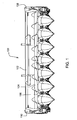
- the row units in the middle of the corn head are covered by light weight roto-molded plastic points and covers (see Figs. 1-2 ) which can be easily raised and lowered by a single operator to provide access to the row unit.
- the end row units which are located at the left and right ends of the corn head, are not as easily cleared of blockages and jams.
- the two fenders on the ends of the vehicle that cover the end row units require wrenches, screwdrivers, or other tools to remove them from the end row units and main frame of the corn head.
- the fender is supported on a hinge located at the upper rear of the fender having a hinge axis that extends laterally and horizontally and that is disposed approximately 60,96-91,44 cm (2-3 feet) up in the air.
- the operator grasps the pointed front end of the fender, lifts it several feet into the air, and walks it backward until it pivots rearward out of the way behind the main frame.
- the fender is made of relatively lightweight materials, the need to lift it so high in the air often requires two people.
- EP 0 848 898 A discloses a corn feeder, that improves the access to the processing equipment for maintenance or transport.
- a fender for a corn head comprising a cover portion that extends generally fore-and-aft and covers a rear portion of a row unit; a point that extends generally fore-and-aft and is pivotally coupled to the forward end of the cover portion to pivot up and down about a generally laterally extending and horizontal axis and to cover a forward end of the row unit; a first hinge member which is fixed to the cover portion; and a second hinge member which is pivotally coupled to the first hinge member to pivot about a generally fore-and-aft extending hinge axis, wherein the second hinge member is fixed relative to a mainframe of the corn head.
- the second hinge member may be fixed to the row unit, and the row unit may be fixed to the mainframe of the corn head.
- the fender may further comprise a spring-loaded latch that couples the upper rear portion of the fender to the mainframe of the corn head, to maintain the fender in a generally upright and vertical position during normal operation when engaged.
- the spring-loaded latch may include a spring pin mounted to the mainframe, and a latch member mounted to the cover portion, and further wherein the spring pin may be disengaged from the latch member by pulling a free end of the spring pin out of an aperture in the latch member against the force of a spring.
- the fender may further comprise a spring-loaded latch that couples the front of the cover portion to the row unit, in order to maintain the fender in a generally upright and vertical position during normal operation when engaged.
- the spring-loaded latch may comprise a spring pin mounted to the cover portion, and a latch member mounted to the row unit, and further wherein the spring pin make be disengaged from the latch member by pulling a free end of the spring pin out of an aperture in the latch member against the force of the spring.
- the spring-loaded latch may be adapted to be automatically held in a spring-compressed and disengaged position without being held by the operator.
- the hinge axis maybe disposed adjacent to the row unit.
- the hinge axis maybe disposed generally parallel to and on the outside of a gathering chain of the row unit.
- forward or “front” refer to the normal direction of travel through a field during harvesting.
- Rear or “backward” refer to the opposite direction.
- Lateral or “side-to-side” refer to directions that are generally horizontal and perpendicular to the normal direction of travel through a field during harvesting.
- a corn head 100 having a laterally extending main frame 102, a laterally extending auger 104, eight row units 106 disposed along the mainframe, and left and right fenders 108, 110.
- the left and right fenders are at the ends of the corn head covering a portion of the end row units and face outward from the very end of the corn head.
- FIG 1 the left and right fenders 108, 110 are in an upright, operating position.
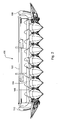
- FIG 2 the left and right fenders are pivoted outward about their respective hinges (not shown) for accessing the row units 106 located underneath the fenders.
- figures 1 and 2 are identical.
- Fenders 108 and 110 are mirror images of each other, and therefore we shall only describe the right fender 110.
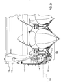
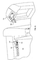
- the right fender 110 is shown in an upright position with its point 112 raised.
- the right fender covers the right side of the end row unit 106. When tilted outward and away from the corn head, it provides access to gathering chain 114 which is otherwise concealed underneath the right fender 110.
- a latch assembly is provided to hold the point in a raised position with respect to the cover portion 118.
- a spring pin 116 extends between cover portion 118 of right fender 110 and point 112 to hold point 112 in an upright position with respect to cover portion 118 as shown in all of the figures herein.
- Point 112 is pivotally coupled to cover portion 118 to permit it to pivot upward with respect to cover portion 118 about a generally horizontal and laterally extending axis 120.
- a spring pin 122 is mounted on a support plate 124, which is in turn fixed to cover portion 118.
- Spring pin 122 extends into an aperture in receiver 126 fixed to end row unit 106 to hold the forward end of the fender 110 in its latched and upright position as shown in figure 1 and figure 3 .
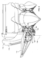
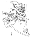
- FIG. 4 shows right fender 110 in its unlatched and outwardly tilted position in which it provides access to the row unit 106 that it covers during harvesting operations.
- right fender 110 has been tilted to the right and away from its row unit 106 about an axis 128 that extends generally fore-and-aft and lies in a laterally extending generally horizontal plane that passes through gathering chain 130.
- axis 128 that extends generally fore-and-aft and lies in a laterally extending generally horizontal plane that passes through gathering chain 130.
- Figure 5 illustrates a latch assembly that holds the right fender 110 in its upright and latched position.
- a spring pin 134 is affixed to the frame 102 of the corn head 100.
- Spring pin 134 is spring-loaded by a spring 136, which holds spring pin 134 in a forwardly extending position in which it engages an aperture in latch member 138 which is attached to the back of right fender 110.
- spring pin 134 can be be manipulated by the operator to a position in which it is disengaged from latch member 138. To do this, spring pin 134 is pulled backwards (towards the viewer in figure 5 ) compressing spring 136.
- Spring number 134 is L-shaped, and can be rotated when in this withdrawn position by 180° where it is supported in its withdrawn and disengaged position by bracket 140. The operator can then circle around to the front of the corn head and disengage the front latch.
- Figure 6 provides additional details of the front of cover portion 118.
- a bracket 142 is bolted to the underside of cover portion 118 and supports spring pin 116 for movement in a generally transverse direction. The end of spring pin 116 extends into an aperture (hidden by bracket 142) in point 112 when it the point 112 is in its upright position as shown in figure 6 .
- spring pin 122 is supported by a bracket 144 which is bolted to a second bracket 124 which is attached to cover portion 118.
- Spring pin 122 extends generally front to rear in the direction of travel and when it is in its spring biased position in engages an aperture 146 and receiver 126.
- Figure 6 illustrates the hinge 148 that supports right fender 110 when it is in its outwardly tilted position. Hinge 148 is better illustrated in the succeeding figure 7-8 , from different perspective views.
- FIG. 7 illustrates the hinge pin 150 itself, which is welded to bracket 152 at its forward end and bracket 154 at its rear end. Brackets 152 and 154, in turn, are bolted to row unit 106. Thus, hinge 148 is supported on row unit 106.
- FIG 8 illustrates how the hinge pin 150 is pivotally coupled to cover portion 118.
- elongated bracket 160 is bolted to the underside of cover portion 118.
- the elongated bracket 160 extends fore-and-aft and surrounds hinge pin 150.
- saddle brackets 162 At either end of elongated bracket 160 are saddle brackets 162 that have a U-shaped aperture that opens downward. These U-shaped apertures receive opposite ends of hinge pin 150.
- Hinge pin 150 is retained within the U-shaped apertures by bolts 164 that extend transversely with respect to hinge pin 150 and prevented from being withdrawn from the U-shaped apertures at each end of elongated bracket 160.
- Hinge pin 150 is free to pivot within the U-shaped apertures, which in turn permits the right fender 110 to pivot about hinge pin 150 with respect to the corn head 100.
Landscapes
- Life Sciences & Earth Sciences (AREA)
- Environmental Sciences (AREA)
- Body Structure For Vehicles (AREA)
- Harvesting Machines For Specific Crops (AREA)
- Superstructure Of Vehicle (AREA)
- Supports For Plants (AREA)
- Threshing Machine Elements (AREA)
Claims (9)
- Schutzblech (108, 110) für einen Maiserntevorsatz (100), umfassend:einen Abdeckteil (118), der sich allgemein in Längsrichtung erstreckt und einen hinteren Teil einer Reiheneinheit (106) abdeckt;eine Spitze (112), die sich allgemein in Längsrichtung erstreckt und schwenkbar mit dem Vorderende des Abdeckteils (118) verbunden ist, um um eine sich allgemein lateral erstreckende und horizontale Achse auf und ab zu schwenken und ein Vorderende der Reiheneinheit (106) abzudecken;ein erstes Scharnierglied (160), das an dem Abdeckteil (118) befestigt ist; undein zweites Scharnierglied (150), das schwenkbar mit dem ersten Scharnierglied (160) verbunden ist, wobei das zweite Scharnierglied (150) bezüglich eines Hauptrahmens (102) des Maiserntevorsatzes (100) festgelegt ist,dadurch gekennzeichnet, dass das zweite Scharnierglied (150) dazu angeordnet ist, um um eine sich allgemein in Längsrichtung erstreckende Scharnierachse (128) zu schwenken.
- Schutzblech (108, 110) nach Anspruch 1, wobei das zweite Scharnierglied (150) an der Reiheneinheit (106) befestigt ist und die Reiheneinheit (106) am Hauptrahmen (102) des Maiserntevorsatzes (100) befestigt ist.
- Schutzblech (108, 110) nach Anspruch 1, das weiterhin eine federbelastete Verriegelung umfasst, die den oberen Hinterteil des Schutzbleches (108, 110) an den Hauptrahmen (102) des Maiserntevorsatzes (100) koppelt, um das Schutzblech (108, 110) bei Normalbetrieb im eingerückten Zustand in einer allgemein aufrechten und vertikalen Position zu halten.
- Schutzblech (108, 110) nach Anspruch 3, wobei die federbelastete Verriegelungsanordnung einen am Hauptrahmen (102) angebrachten Federstift (134) und ein am Abdeckteil (118) angebrachtes Verriegelungsglied (138) enthält, und wobei weiterhin der Federstift (134) aus dem Verriegelungsglied (138) ausgerückt werden kann, indem ein freies Ende des Federstifts (134) gegen die Kraft einer Feder (136) aus einer Öffnung im Verriegelungsglied (138) gezogen wird.
- Schutzblech (108, 110) nach Anspruch 1, das weiterhin eine federbelastete Verriegelungsanordnung umfasst, die das vordere Ende des Abdeckteils (118) an die Reiheneinheit (106) koppelt, um das Schutzblech bei Normalbetrieb im eingerückten Zustand in einer allgemein aufrechten und vertikalen Position zu halten.
- Schutzblech (108, 110) nach Anspruch 5, wobei die federbelastete Verriegelungsanordnung einen am Abdeckteil (118) angebrachten Federstift (134) und ein an der Reiheneinheit (106) angebrachtes Verriegelungsglied (138) enthält, und wobei weiterhin der Federstift (134) aus dem Verriegelungsglied (138) ausgerückt werden kann, indem ein freies Ende des Federstifts (134) gegen die Kraft einer Feder (136) aus einer Öffnung im Verriegelungsglied (138) gezogen wird.
- Schutzblech (108, 110) nach Anspruch 4, wobei die federbelastete Verriegelungsanordnung dazu ausgeführt ist, automatisch in einer federkomprimierten und ausgerückten Position gehalten zu werden, ohne von dem Bediener festgehalten zu werden.
- Schutzblech (108, 110) nach Anspruch 1, wobei die Scharnierachse (128) neben der Reiheneinheit (106) angeordnet ist.
- Schutzblech (108, 110) nach Anspruch 8, wobei die Scharnierachse (128) allgemein parallel zu und auf der Außenseite einer Sammelkette (114) der Reiheneinheit (106) angeordnet ist.
Applications Claiming Priority (1)
| Application Number | Priority Date | Filing Date | Title |
|---|---|---|---|
| US95193207P | 2007-07-25 | 2007-07-25 |
Publications (2)
| Publication Number | Publication Date |
|---|---|
| EP2018802A1 EP2018802A1 (de) | 2009-01-28 |
| EP2018802B1 true EP2018802B1 (de) | 2011-01-26 |
Family
ID=39831925
Family Applications (1)
| Application Number | Title | Priority Date | Filing Date |
|---|---|---|---|
| EP08158108A Not-in-force EP2018802B1 (de) | 2007-07-25 | 2008-06-12 | Neigungsfähiges Maiserntekopfschutzblech |
Country Status (10)
| Country | Link |
|---|---|
| US (1) | US7681387B2 (de) |
| EP (1) | EP2018802B1 (de) |
| AR (1) | AR067638A1 (de) |
| AT (1) | ATE496528T1 (de) |
| AU (1) | AU2008202647B2 (de) |
| BR (1) | BRPI0803672A2 (de) |
| CA (1) | CA2635458A1 (de) |
| DE (1) | DE602008004699D1 (de) |
| RU (1) | RU2468564C2 (de) |
| UA (1) | UA96584C2 (de) |
Cited By (1)
| Publication number | Priority date | Publication date | Assignee | Title |
|---|---|---|---|---|
| EP3863395B1 (de) * | 2018-10-12 | 2022-12-21 | CNH Industrial Belgium NV | Ein stellbar ährensperre für einen maiserntevorsatz |
Families Citing this family (20)
| Publication number | Priority date | Publication date | Assignee | Title |
|---|---|---|---|---|
| US8635842B2 (en) * | 2009-08-05 | 2014-01-28 | Kevin Markt | Flexible row crop header for an agricultural harvester |
| AR076568A1 (es) * | 2010-05-11 | 2011-06-22 | Allochis Jose Luis | Cabezal maicero con puntones y capot laterales articulados. |
| US8387352B2 (en) * | 2011-05-20 | 2013-03-05 | Deere & Company | Cornhead divider lift assist linkage |
| US9253944B2 (en) * | 2012-11-12 | 2016-02-09 | Dragotec Usa, Inc. | Snout height and tension adjustment |
| US9032700B2 (en) * | 2013-03-13 | 2015-05-19 | Agco Corporation | Folding divider assembly for corn header and method of operation |
| US20150101303A1 (en) * | 2013-10-15 | 2015-04-16 | Cnh America Llc | Row divider for a corn header of a combine harvester |
| CN103563574A (zh) * | 2013-10-21 | 2014-02-12 | 杨龙龙 | 玉米割台剥皮机 |
| US9265198B2 (en) * | 2013-11-12 | 2016-02-23 | Dragotec Usa, Inc. | Harvester head assembly with apparatus for guiding harvested crops |
| BE1021401B1 (nl) * | 2014-09-03 | 2015-11-16 | Cnh Industrial Belgium Nv | Inklapbare gewasmaaier |
| PL2992751T3 (pl) * | 2014-09-05 | 2018-01-31 | Exel Ind | Układ zbierający do zebranych plonów i odpowiednia maszyna zbierająca |
| US9642307B2 (en) * | 2015-05-08 | 2017-05-09 | Cnh Industrial America Llc | Header end hood mount for an agricultural harvester |
| CN106068912A (zh) * | 2016-03-21 | 2016-11-09 | 安徽农业大学 | 一种玉米收获机割台 |
| US10159188B2 (en) | 2016-08-26 | 2018-12-25 | Cnh Industrial America Llc | Corn harvester with tall corn attachment and associated methods |
| US10159186B2 (en) | 2016-08-26 | 2018-12-25 | CNH Industrial America, LLC | Corn harvester with tall corn attachment and auger and associated methods |
| US10674652B2 (en) * | 2018-01-29 | 2020-06-09 | Cnh Industrial America Llc | Harvester with adjustable row dividers |
| US10694654B2 (en) * | 2018-01-29 | 2020-06-30 | Cnh Industrial America Llc | Automatic divider height positioning for an agricultural harvester |
| US10897846B2 (en) * | 2018-10-31 | 2021-01-26 | Deere & Company | Corn harvester |
| US11234371B2 (en) * | 2019-08-07 | 2022-02-01 | Cnh Industrial America Llc | Tool-less folding divider for combine head |
| US11570950B2 (en) * | 2020-07-17 | 2023-02-07 | Deere & Company | Folding harvester with crop divider lift and frame lock |
| CN112205159A (zh) * | 2020-10-20 | 2021-01-12 | 九方泰禾国际重工(青岛)股份有限公司 | 一种五行纵置摘穗式的穗茎兼收玉米收获机割台 |
Family Cites Families (16)
| Publication number | Priority date | Publication date | Assignee | Title |
|---|---|---|---|---|
| FR2192443A5 (de) | 1971-01-12 | 1974-02-08 | Lagouarde Jean | |
| DE3213542A1 (de) * | 1982-04-10 | 1983-10-20 | Klemens 4730 Ahlen Kalverkamp | Verfahren und geraet zum ernten von mais oder anderen koernerfruechten |
| US4538404A (en) * | 1983-08-16 | 1985-09-03 | General Dryer Corporation | Adjustable crop divider apparatus |
| US4493181A (en) * | 1984-05-14 | 1985-01-15 | Farmer's Factory Co. | Attachment for the snouts of combines and the like |
| EP0215142B1 (de) * | 1985-09-14 | 1990-06-06 | Deere & Company | Halmteiler für landwirtschaftliche Maschinen |
| US4757673A (en) * | 1986-07-29 | 1988-07-19 | Charles Gayman | Adjustment of crop dividers |
| SU1628914A1 (ru) * | 1988-11-15 | 1991-02-23 | Всероссийский научно-исследовательский и проектно-технологический институт механизации и электрификации сельского хозяйства | Кукурузоуборочна приставка |
| DE19523255A1 (de) * | 1995-06-27 | 1997-01-02 | Claas Saulgau Gmbh | Erntevorsatz an landwirtschaftlichen Arbeitsmaschinen zum Aufnehmen und Weiterführen von Halmfrüchten, beispielsweise Maispflanzen |
| US5787697A (en) * | 1996-07-08 | 1998-08-04 | Vande Weerd Combine, Inc. | Combine crop divider assembly |
| US5865019A (en) * | 1996-12-17 | 1999-02-02 | New Holland North America, Inc. | Plastic divider assembly with frame for a corn head |
| US5910092A (en) * | 1997-09-22 | 1999-06-08 | Case Corporation | Row crop header shield with detachable shields |
| DE19911827A1 (de) * | 1999-03-17 | 2000-09-28 | Deere & Co | Halmteiler |
| US6247297B1 (en) * | 1999-08-20 | 2001-06-19 | Case Corporation | Jackknife support system for a combine cornhead |
| DE10221983A1 (de) * | 2002-05-17 | 2003-11-27 | Kemper Gmbh Maschf | Erntevorsatz |
| GB2392600A (en) * | 2002-09-04 | 2004-03-10 | Cnh Belgium Nv | Cutting platform for a combine harvester |
| BRPI0700408B1 (pt) * | 2006-02-17 | 2016-04-19 | Deere & Co | conjunto de ponta e tampa para um cabeçote de colheita de fileira |
-
2007
- 2007-10-30 US US11/928,878 patent/US7681387B2/en not_active Expired - Fee Related
-
2008
- 2008-06-12 DE DE602008004699T patent/DE602008004699D1/de active Active
- 2008-06-12 EP EP08158108A patent/EP2018802B1/de not_active Not-in-force
- 2008-06-12 AT AT08158108T patent/ATE496528T1/de not_active IP Right Cessation
- 2008-06-13 AU AU2008202647A patent/AU2008202647B2/en not_active Ceased
- 2008-06-19 CA CA002635458A patent/CA2635458A1/en not_active Abandoned
- 2008-06-20 UA UAA200808301A patent/UA96584C2/ru unknown
- 2008-07-14 BR BRPI0803672-1A patent/BRPI0803672A2/pt active Search and Examination
- 2008-07-21 AR ARP080103158A patent/AR067638A1/es active IP Right Grant
- 2008-07-24 RU RU2008130774/12A patent/RU2468564C2/ru not_active IP Right Cessation
Cited By (1)
| Publication number | Priority date | Publication date | Assignee | Title |
|---|---|---|---|---|
| EP3863395B1 (de) * | 2018-10-12 | 2022-12-21 | CNH Industrial Belgium NV | Ein stellbar ährensperre für einen maiserntevorsatz |
Also Published As
| Publication number | Publication date |
|---|---|
| UA96584C2 (ru) | 2011-11-25 |
| CA2635458A1 (en) | 2009-01-25 |
| BRPI0803672A2 (pt) | 2009-11-24 |
| RU2468564C2 (ru) | 2012-12-10 |
| AU2008202647B2 (en) | 2012-11-22 |
| US7681387B2 (en) | 2010-03-23 |
| RU2008130774A (ru) | 2010-01-27 |
| US20090025354A1 (en) | 2009-01-29 |
| ATE496528T1 (de) | 2011-02-15 |
| AR067638A1 (es) | 2009-10-21 |
| DE602008004699D1 (de) | 2011-03-10 |
| EP2018802A1 (de) | 2009-01-28 |
| AU2008202647A1 (en) | 2009-02-12 |
Similar Documents
| Publication | Publication Date | Title |
|---|---|---|
| EP2018802B1 (de) | Neigungsfähiges Maiserntekopfschutzblech | |
| US10993371B2 (en) | Flexible row crop header for an agricultural harvester | |
| US6247297B1 (en) | Jackknife support system for a combine cornhead | |
| US5865019A (en) | Plastic divider assembly with frame for a corn head | |
| EP3308624B1 (de) | Mähdreschereinzugsgehäusemessräder | |
| US7992372B1 (en) | Draper platform with breakaway joint | |
| US4182098A (en) | Apparatus and method for harvesting and windrowing corn | |
| EP3516944B1 (de) | Automatische trennerhöhenpositionierung für eine landwirtschaftliche erntemaschine | |
| EP3090620B1 (de) | Endabdeckhaubenhalterung eines erntevorsatzes für eine landwiretschaftliche erntemaschine | |
| USRE37267E1 (en) | Combine harvester with secondary cutter | |
| EP1820384B1 (de) | Verbundschraubenausräumtür | |
| US7644567B2 (en) | Flexible tall crop pusher | |
| CA1110853A (en) | Forage harvester corn snapping header | |
| KR102667806B1 (ko) | 탈착식 조사료 수확용 자동화기기 | |
| US4238916A (en) | Corn snapping header frame | |
| JPH06253652A (ja) | 全稈投入型コンバインの刈取収穫構造 | |
| US20240138307A1 (en) | Retractable crop divider of an agricultural header | |
| JP2014212744A (ja) | コンバイン | |
| JP2607045B2 (ja) | コンバインの補助刈取装置取付構造 |
Legal Events
| Date | Code | Title | Description |
|---|---|---|---|
| PUAI | Public reference made under article 153(3) epc to a published international application that has entered the european phase |
Free format text: ORIGINAL CODE: 0009012 |
|
| AK | Designated contracting states |
Kind code of ref document: A1 Designated state(s): AT BE BG CH CY CZ DE DK EE ES FI FR GB GR HR HU IE IS IT LI LT LU LV MC MT NL NO PL PT RO SE SI SK TR |
|
| AX | Request for extension of the european patent |
Extension state: AL BA MK RS |
|
| 17P | Request for examination filed |
Effective date: 20090728 |
|
| AKX | Designation fees paid |
Designated state(s): AT BE BG CH CY CZ DE DK EE ES FI FR GB GR HR HU IE IS IT LI LT LU LV MC MT NL NO PL PT RO SE SI SK TR |
|
| GRAP | Despatch of communication of intention to grant a patent |
Free format text: ORIGINAL CODE: EPIDOSNIGR1 |
|
| GRAS | Grant fee paid |
Free format text: ORIGINAL CODE: EPIDOSNIGR3 |
|
| GRAA | (expected) grant |
Free format text: ORIGINAL CODE: 0009210 |
|
| AK | Designated contracting states |
Kind code of ref document: B1 Designated state(s): AT BE BG CH CY CZ DE DK EE ES FI FR GB GR HR HU IE IS IT LI LT LU LV MC MT NL NO PL PT RO SE SI SK TR |
|
| REG | Reference to a national code |
Ref country code: GB Ref legal event code: FG4D |
|
| REG | Reference to a national code |
Ref country code: CH Ref legal event code: EP |
|
| REG | Reference to a national code |
Ref country code: IE Ref legal event code: FG4D |
|
| REF | Corresponds to: |
Ref document number: 602008004699 Country of ref document: DE Date of ref document: 20110310 Kind code of ref document: P |
|
| REG | Reference to a national code |
Ref country code: DE Ref legal event code: R096 Ref document number: 602008004699 Country of ref document: DE Effective date: 20110310 |
|
| REG | Reference to a national code |
Ref country code: NL Ref legal event code: VDEP Effective date: 20110126 |
|
| LTIE | Lt: invalidation of european patent or patent extension |
Effective date: 20110126 |
|
| PG25 | Lapsed in a contracting state [announced via postgrant information from national office to epo] |
Ref country code: PT Free format text: LAPSE BECAUSE OF FAILURE TO SUBMIT A TRANSLATION OF THE DESCRIPTION OR TO PAY THE FEE WITHIN THE PRESCRIBED TIME-LIMIT Effective date: 20110526 Ref country code: IS Free format text: LAPSE BECAUSE OF FAILURE TO SUBMIT A TRANSLATION OF THE DESCRIPTION OR TO PAY THE FEE WITHIN THE PRESCRIBED TIME-LIMIT Effective date: 20110526 Ref country code: ES Free format text: LAPSE BECAUSE OF FAILURE TO SUBMIT A TRANSLATION OF THE DESCRIPTION OR TO PAY THE FEE WITHIN THE PRESCRIBED TIME-LIMIT Effective date: 20110507 Ref country code: NO Free format text: LAPSE BECAUSE OF FAILURE TO SUBMIT A TRANSLATION OF THE DESCRIPTION OR TO PAY THE FEE WITHIN THE PRESCRIBED TIME-LIMIT Effective date: 20110426 Ref country code: GR Free format text: LAPSE BECAUSE OF FAILURE TO SUBMIT A TRANSLATION OF THE DESCRIPTION OR TO PAY THE FEE WITHIN THE PRESCRIBED TIME-LIMIT Effective date: 20110427 Ref country code: LT Free format text: LAPSE BECAUSE OF FAILURE TO SUBMIT A TRANSLATION OF THE DESCRIPTION OR TO PAY THE FEE WITHIN THE PRESCRIBED TIME-LIMIT Effective date: 20110126 Ref country code: LV Free format text: LAPSE BECAUSE OF FAILURE TO SUBMIT A TRANSLATION OF THE DESCRIPTION OR TO PAY THE FEE WITHIN THE PRESCRIBED TIME-LIMIT Effective date: 20110126 Ref country code: HR Free format text: LAPSE BECAUSE OF FAILURE TO SUBMIT A TRANSLATION OF THE DESCRIPTION OR TO PAY THE FEE WITHIN THE PRESCRIBED TIME-LIMIT Effective date: 20110126 Ref country code: SE Free format text: LAPSE BECAUSE OF FAILURE TO SUBMIT A TRANSLATION OF THE DESCRIPTION OR TO PAY THE FEE WITHIN THE PRESCRIBED TIME-LIMIT Effective date: 20110126 |
|
| PG25 | Lapsed in a contracting state [announced via postgrant information from national office to epo] |
Ref country code: AT Free format text: LAPSE BECAUSE OF FAILURE TO SUBMIT A TRANSLATION OF THE DESCRIPTION OR TO PAY THE FEE WITHIN THE PRESCRIBED TIME-LIMIT Effective date: 20110126 Ref country code: PL Free format text: LAPSE BECAUSE OF FAILURE TO SUBMIT A TRANSLATION OF THE DESCRIPTION OR TO PAY THE FEE WITHIN THE PRESCRIBED TIME-LIMIT Effective date: 20110126 Ref country code: NL Free format text: LAPSE BECAUSE OF FAILURE TO SUBMIT A TRANSLATION OF THE DESCRIPTION OR TO PAY THE FEE WITHIN THE PRESCRIBED TIME-LIMIT Effective date: 20110126 Ref country code: SI Free format text: LAPSE BECAUSE OF FAILURE TO SUBMIT A TRANSLATION OF THE DESCRIPTION OR TO PAY THE FEE WITHIN THE PRESCRIBED TIME-LIMIT Effective date: 20110126 Ref country code: CY Free format text: LAPSE BECAUSE OF FAILURE TO SUBMIT A TRANSLATION OF THE DESCRIPTION OR TO PAY THE FEE WITHIN THE PRESCRIBED TIME-LIMIT Effective date: 20110126 Ref country code: FI Free format text: LAPSE BECAUSE OF FAILURE TO SUBMIT A TRANSLATION OF THE DESCRIPTION OR TO PAY THE FEE WITHIN THE PRESCRIBED TIME-LIMIT Effective date: 20110126 Ref country code: BG Free format text: LAPSE BECAUSE OF FAILURE TO SUBMIT A TRANSLATION OF THE DESCRIPTION OR TO PAY THE FEE WITHIN THE PRESCRIBED TIME-LIMIT Effective date: 20110426 |
|
| PG25 | Lapsed in a contracting state [announced via postgrant information from national office to epo] |
Ref country code: EE Free format text: LAPSE BECAUSE OF FAILURE TO SUBMIT A TRANSLATION OF THE DESCRIPTION OR TO PAY THE FEE WITHIN THE PRESCRIBED TIME-LIMIT Effective date: 20110126 Ref country code: DK Free format text: LAPSE BECAUSE OF FAILURE TO SUBMIT A TRANSLATION OF THE DESCRIPTION OR TO PAY THE FEE WITHIN THE PRESCRIBED TIME-LIMIT Effective date: 20110126 |
|
| PG25 | Lapsed in a contracting state [announced via postgrant information from national office to epo] |
Ref country code: CZ Free format text: LAPSE BECAUSE OF FAILURE TO SUBMIT A TRANSLATION OF THE DESCRIPTION OR TO PAY THE FEE WITHIN THE PRESCRIBED TIME-LIMIT Effective date: 20110126 Ref country code: RO Free format text: LAPSE BECAUSE OF FAILURE TO SUBMIT A TRANSLATION OF THE DESCRIPTION OR TO PAY THE FEE WITHIN THE PRESCRIBED TIME-LIMIT Effective date: 20110126 Ref country code: SK Free format text: LAPSE BECAUSE OF FAILURE TO SUBMIT A TRANSLATION OF THE DESCRIPTION OR TO PAY THE FEE WITHIN THE PRESCRIBED TIME-LIMIT Effective date: 20110126 |
|
| PLBE | No opposition filed within time limit |
Free format text: ORIGINAL CODE: 0009261 |
|
| STAA | Information on the status of an ep patent application or granted ep patent |
Free format text: STATUS: NO OPPOSITION FILED WITHIN TIME LIMIT |
|
| PG25 | Lapsed in a contracting state [announced via postgrant information from national office to epo] |
Ref country code: MT Free format text: LAPSE BECAUSE OF FAILURE TO SUBMIT A TRANSLATION OF THE DESCRIPTION OR TO PAY THE FEE WITHIN THE PRESCRIBED TIME-LIMIT Effective date: 20110126 |
|
| 26N | No opposition filed |
Effective date: 20111027 |
|
| REG | Reference to a national code |
Ref country code: DE Ref legal event code: R097 Ref document number: 602008004699 Country of ref document: DE Effective date: 20111027 |
|
| REG | Reference to a national code |
Ref country code: FR Ref legal event code: ST Effective date: 20120229 |
|
| REG | Reference to a national code |
Ref country code: IE Ref legal event code: MM4A |
|
| PG25 | Lapsed in a contracting state [announced via postgrant information from national office to epo] |
Ref country code: IE Free format text: LAPSE BECAUSE OF NON-PAYMENT OF DUE FEES Effective date: 20110612 Ref country code: FR Free format text: LAPSE BECAUSE OF NON-PAYMENT OF DUE FEES Effective date: 20110630 |
|
| REG | Reference to a national code |
Ref country code: CH Ref legal event code: PL |
|
| REG | Reference to a national code |
Ref country code: CH Ref legal event code: PL |
|
| GBPC | Gb: european patent ceased through non-payment of renewal fee |
Effective date: 20120612 |
|
| PG25 | Lapsed in a contracting state [announced via postgrant information from national office to epo] |
Ref country code: GB Free format text: LAPSE BECAUSE OF NON-PAYMENT OF DUE FEES Effective date: 20120612 Ref country code: LI Free format text: LAPSE BECAUSE OF NON-PAYMENT OF DUE FEES Effective date: 20120630 Ref country code: MC Free format text: LAPSE BECAUSE OF NON-PAYMENT OF DUE FEES Effective date: 20110630 Ref country code: CH Free format text: LAPSE BECAUSE OF NON-PAYMENT OF DUE FEES Effective date: 20120630 |
|
| PG25 | Lapsed in a contracting state [announced via postgrant information from national office to epo] |
Ref country code: LU Free format text: LAPSE BECAUSE OF NON-PAYMENT OF DUE FEES Effective date: 20110612 |
|
| PG25 | Lapsed in a contracting state [announced via postgrant information from national office to epo] |
Ref country code: TR Free format text: LAPSE BECAUSE OF FAILURE TO SUBMIT A TRANSLATION OF THE DESCRIPTION OR TO PAY THE FEE WITHIN THE PRESCRIBED TIME-LIMIT Effective date: 20110126 |
|
| PG25 | Lapsed in a contracting state [announced via postgrant information from national office to epo] |
Ref country code: HU Free format text: LAPSE BECAUSE OF FAILURE TO SUBMIT A TRANSLATION OF THE DESCRIPTION OR TO PAY THE FEE WITHIN THE PRESCRIBED TIME-LIMIT Effective date: 20110126 |
|
| PGFP | Annual fee paid to national office [announced via postgrant information from national office to epo] |
Ref country code: IT Payment date: 20140621 Year of fee payment: 7 |
|
| PG25 | Lapsed in a contracting state [announced via postgrant information from national office to epo] |
Ref country code: IT Free format text: LAPSE BECAUSE OF NON-PAYMENT OF DUE FEES Effective date: 20150612 |
|
| PGFP | Annual fee paid to national office [announced via postgrant information from national office to epo] |
Ref country code: DE Payment date: 20200520 Year of fee payment: 13 |
|
| PGFP | Annual fee paid to national office [announced via postgrant information from national office to epo] |
Ref country code: BE Payment date: 20200629 Year of fee payment: 13 |
|
| REG | Reference to a national code |
Ref country code: DE Ref legal event code: R119 Ref document number: 602008004699 Country of ref document: DE |
|
| REG | Reference to a national code |
Ref country code: BE Ref legal event code: MM Effective date: 20210630 |
|
| PG25 | Lapsed in a contracting state [announced via postgrant information from national office to epo] |
Ref country code: DE Free format text: LAPSE BECAUSE OF NON-PAYMENT OF DUE FEES Effective date: 20220101 |
|
| PG25 | Lapsed in a contracting state [announced via postgrant information from national office to epo] |
Ref country code: BE Free format text: LAPSE BECAUSE OF NON-PAYMENT OF DUE FEES Effective date: 20210630 |