EP2018795B1 - Integrated lighting control module and power switch - Google Patents
Integrated lighting control module and power switch Download PDFInfo
- Publication number
- EP2018795B1 EP2018795B1 EP07735739.0A EP07735739A EP2018795B1 EP 2018795 B1 EP2018795 B1 EP 2018795B1 EP 07735739 A EP07735739 A EP 07735739A EP 2018795 B1 EP2018795 B1 EP 2018795B1
- Authority
- EP
- European Patent Office
- Prior art keywords
- control module
- light source
- switch
- power
- lighting system
- Prior art date
- Legal status (The legal status is an assumption and is not a legal conclusion. Google has not performed a legal analysis and makes no representation as to the accuracy of the status listed.)
- Active
Links
- 238000000034 method Methods 0.000 claims description 19
- 230000004044 response Effects 0.000 claims description 8
- 238000005286 illumination Methods 0.000 claims 2
- 230000015654 memory Effects 0.000 description 23
- 230000006870 function Effects 0.000 description 4
- 230000008901 benefit Effects 0.000 description 2
- 230000008859 change Effects 0.000 description 2
- 239000003086 colorant Substances 0.000 description 2
- 230000004048 modification Effects 0.000 description 2
- 238000012986 modification Methods 0.000 description 2
- 230000003287 optical effect Effects 0.000 description 2
- 230000008569 process Effects 0.000 description 2
- 230000006399 behavior Effects 0.000 description 1
- 230000005540 biological transmission Effects 0.000 description 1
- 230000001419 dependent effect Effects 0.000 description 1
- 238000001514 detection method Methods 0.000 description 1
- 229910052736 halogen Inorganic materials 0.000 description 1
- 150000002367 halogens Chemical class 0.000 description 1
- 238000009434 installation Methods 0.000 description 1
- 230000010354 integration Effects 0.000 description 1
- 230000007774 longterm Effects 0.000 description 1
- 230000002093 peripheral effect Effects 0.000 description 1
- 238000009877 rendering Methods 0.000 description 1
- 230000001052 transient effect Effects 0.000 description 1
Images

Classifications
-
- H—ELECTRICITY
- H05—ELECTRIC TECHNIQUES NOT OTHERWISE PROVIDED FOR
- H05B—ELECTRIC HEATING; ELECTRIC LIGHT SOURCES NOT OTHERWISE PROVIDED FOR; CIRCUIT ARRANGEMENTS FOR ELECTRIC LIGHT SOURCES, IN GENERAL
- H05B47/00—Circuit arrangements for operating light sources in general, i.e. where the type of light source is not relevant
- H05B47/10—Controlling the light source
- H05B47/175—Controlling the light source by remote control
- H05B47/19—Controlling the light source by remote control via wireless transmission
-
- H—ELECTRICITY
- H05—ELECTRIC TECHNIQUES NOT OTHERWISE PROVIDED FOR
- H05B—ELECTRIC HEATING; ELECTRIC LIGHT SOURCES NOT OTHERWISE PROVIDED FOR; CIRCUIT ARRANGEMENTS FOR ELECTRIC LIGHT SOURCES, IN GENERAL
- H05B47/00—Circuit arrangements for operating light sources in general, i.e. where the type of light source is not relevant
- H05B47/10—Controlling the light source
- H05B47/175—Controlling the light source by remote control
- H05B47/185—Controlling the light source by remote control via power line carrier transmission
-
- F—MECHANICAL ENGINEERING; LIGHTING; HEATING; WEAPONS; BLASTING
- F21—LIGHTING
- F21W—INDEXING SCHEME ASSOCIATED WITH SUBCLASSES F21K, F21L, F21S and F21V, RELATING TO USES OR APPLICATIONS OF LIGHTING DEVICES OR SYSTEMS
- F21W2131/00—Use or application of lighting devices or systems not provided for in codes F21W2102/00-F21W2121/00
- F21W2131/30—Lighting for domestic or personal use
-
- H—ELECTRICITY
- H05—ELECTRIC TECHNIQUES NOT OTHERWISE PROVIDED FOR
- H05B—ELECTRIC HEATING; ELECTRIC LIGHT SOURCES NOT OTHERWISE PROVIDED FOR; CIRCUIT ARRANGEMENTS FOR ELECTRIC LIGHT SOURCES, IN GENERAL
- H05B47/00—Circuit arrangements for operating light sources in general, i.e. where the type of light source is not relevant
- H05B47/10—Controlling the light source
- H05B47/175—Controlling the light source by remote control
- H05B47/19—Controlling the light source by remote control via wireless transmission
- H05B47/195—Controlling the light source by remote control via wireless transmission the transmission using visible or infrared light
Definitions
- the present invention relates to lighting systems and methods for turning lights on in response to toggling a switch more than once within a predetermined time period, for example.
- Figs. 1-2 show typical lighting systems 100, 200, respectively.
- a switch 110, 210 is wired to the main power, e.g., 110 VAC in the United States and 220 VAC in many other countries.
- the switch 110, 210 is further connected by wires 115, 215 to a light source or luminaire 120, 220 including the light source, such as the luminaire 120 located in the ceiling shown in Fig. 1 .
- the switch 210 may also be connected by wires 215 to a wall outlet 230, referred to as a switched outlet.
- the light source/luminaire 220 is plugged into the switched outlet 230. Toggling the switches 110, 210 ON/OFF turns ON/OFF the power and thus the light sources 120, 220.
- WO 98/27792 A discloses a lighting system for step dimming of a fluorescent lamp through sensing of power line interruptions generated through the toggling of a switch. This allows adding the further functionality of dimming to a conventionally wired and switched original lighting system.
- New home lighting control systems are being added to provide further flexibility, such as remotely turning the lights ON/OFF.
- a lighting device that comprises at least one receiver capable of detecting an IR code is installable on a light bulb. It can be operated by a remote control, for example an IR remote control.
- a light source is switched via an original switch 110, 210 (as shown in Figs. 1-2 ), and the consumer replaces the light source with a new module that enables (remote) control of the light source connected to the new module
- the power to the new module will be provided through the switch 110, 210.
- the switch 110, 210 provides switched power from the main power (e.g., 110 VAC) or from other sources such as a DC power converted/derived from the main power. Toggling the switch 110, 210 OFF to turn off the lights 120, 220 will also turn off power to the new module thus potentially causing problems.
- the benefit of having a system installed by the consumer instead of a professional installer introduces problems such as the above-described problem including powering off the new control system and rendering it inoperative (as will be described), as well as not being able to turn the lights ON, when the wall switch 110, 220 is toggled once to the supposedly ON position.
- one object of the present system and method is to provide lighting controls which is intuitive to use and simple to install.
- a lighting system that comprises a light source and a control module that is configured to receive the switched power and remote control signals and to control the light source.
- the control module is further configured to turn the light source on and off by providing or not the switched power to the light source in response to received remote control signals, and to turn the light source on in response to detecting an interrupt in the received switched power if the length of the power-interrupt lies within a predetermined time period.
- the present systems and methods make use of the expected behavior of the end-user, e.g., when the intent is to switch on a light.
- the user When the light is off, and the user wants to switch on the light(s), the user will toggle the light switch once. If the power of the new light control module is cut-off or interrupted in response to toggling the light switch once, then the light(s) will not turn on and will stay off, even when a remote controller associated with the new light control module is activated. However, the typical user will toggle the light switch again since the user will not understand why the light(s) did not switch on. The control module will detect this sequence of toggling the switch more than once, and turn on the light(s).
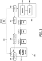
- Fig. 3 shows a lighting system 300 according to one embodiment including an intelligent control module 340.
- a switch 310 is configured to switch power ON/OFF in response to being toggled.
- the switch 310 switches power provided from a main power source 305, such as 110 VAC or 220VAC.
- a main power source 305 such as 110 VAC or 220VAC.
- any other power type or source may be switched by the switch 310.
- the output of the switch 310 is provided directly to the control module 340.
- the switch power may be provided to a power outlet 330, which may be a wall switched power outlet, similar to the switched power outlet 230 shown in Fig. 2 for example.
- the optional switched power outlet 330 is shown in dashed lines in Fig. 3 .
- the control module 340 receiving the switch power is connected to a light source or luminaire including or housing the light source 320.
- the control module 340 is configured to be attachable to the luminaire, such as screwed into the luminaire, instead of the light source.
- the light source is attachable, e.g., screwed into the control module 340, thus providing a simple installation.
- the control module 340 is configured to control the light or lights 320 connected thereto independent from the switch 310.
- the lights 320 are turned on by the switch 310, which may be the original switch included in the original lighting system.
- the control module 340 may be controlled by a remote controller 350 for example.
- the control module 340 and remote controller 350 may be linked or communicate via any communication link, such as wired or wireless.
- wireless communication is more convenient, as it does not require adding wires to connect control module 340 to the remote controller 350 and/or to a further switch.
- the wireless communication may be by any suitable means, such as via radio frequency (RF), infrared (IR), sonar, optical etc.
- RF radio frequency
- IR infrared
- sonar optical etc.
- short range wireless protocols may be used, such as Bluetooth, Zigbee, Z-wave, X10 etc.
- control module 340 and remote controller 350 may be included in the control module 340 and remote controller 350, such as one or more transmitters, receivers, or transceivers, antennas, modulators, demodulators, converters, duplexers, filters, multiplexers etc., which will not be further described in order not to obscure description of the present system and method.
- a system controller 360 including a processor 370 and memory 380 may also be provided where the processor executes instruction stored in the memory, which may also store other data, such as predetermined or programmable settings related to control of the light sources, including programmable times to turn the lights on/off, and change light attributes, such as intensity (i.e., dimming function), color, hue, saturation and the like, for the case of light source that may be controlled to change attributes of light emanating therefrom.
- predetermined or programmable settings related to control of the light sources including programmable times to turn the lights on/off
- change light attributes such as intensity (i.e., dimming function), color, hue, saturation and the like, for the case of light source that may be controlled to change attributes of light emanating therefrom.
- the various component of the lighting system 300 may be operationally coupled to each other (including the system controller 360) by any type of link, including wired or wireless link(s), for example.
- the switch 310 may be wirelessly controlled by its own remote controller to provide the switched power.
- further units may be configured to communicate with and control the control module 340.
- Such further units may be one or more of the following units: a personal digital assistant (PDA), mobile phone, laptop or personal computer, etc., which may act or be programmed to act as the system controller 360 and/or the remote controller 350.
- PDA personal digital assistant
- LEDs Light emitting diodes
- LEDs are light sources that are particularly well suited to controllably provide light of varying attributes, as LEDs may easily be configured to provide light with changing colors, intensity, hue, saturation and other attributes, and typically have electronic drive circuitry for control and adjustment of the various light attributes.
- any controllable light source may be used that is capable of providing lights of various attributes, such as various intensity levels, different colors, hue, saturation and the like, such as incandescent, fluorescent, halogen, or high intensity discharge (HID) light and the like, which may have a ballast or drivers for control of the various light attributes.
- HID high intensity discharge
- the light or lights 320 connected to the control module 340 are turned ON by the switch 310, but later are turned OFF by the control unit 340, e.g., under the control of the remote controller 350.
- the switch 310 is in the ON position, thus providing switched power to the control module 340, but the lights 320 are OFF.
- a user enters the room, e.g., when it's dark, and wishes to turn the lights on. The user touches the wall near the door where light switches are typically located, looking for the light switch 310 (e.g., in the dark).
- the intelligent light switch or control module 340 recognizes the intent of the user to turn on the lights and thus does turn on the lights 320. Such a reaction or recognition of the control module 340 may be based on one or more parameters, such as based on the sequence of toggling the switch 310 more than once, such as twice, in a predetermined time period. This switching sequence parameter (e.g., switched twice in a short time) may be combined for better results with one or more other parameters such as:
- the system and method will switch on the light, e.g., in a default setting such as a default intensity and the like, based on the conclusion that the user wanted or intended to turn the lights on.
- the memory 380 may be any type of device for storing application data as well as other data.
- the application data and other data are received by the system controller 360 or processor 370 for configuring it to perform operation acts in accordance with the present systems and methods.
- the operation acts of the present methods are particularly suited to be carried out by a computer software program, such computer software program preferably containing modules corresponding to the individual steps or acts of the methods.
- a computer software program such computer software program preferably containing modules corresponding to the individual steps or acts of the methods.
- Such software can of course be embodied in a computer-readable medium, such as an integrated chip, a peripheral device or memory, such as the memory 380 or other memory coupled to the processor 370 of the system controller 360 or a processor of the control module 340.
- the computer-readable medium and/or memory 380 may be any recordable medium (e.g., RAM, ROM, removable memory, CD-ROM, hard drives, DVD, floppy disks or memory cards) or may be a transmission medium (e.g., a network comprising fiber-optics, the world-wide web, cables, and/or a wireless channel using, for example, time-division multiple access, code-division multiple access, or other wireless communication systems). Any medium known or developed that can store information suitable for use with a computer system may be used as the computer-readable medium and/or memory 380.
- any medium known or developed that can store information suitable for use with a computer system may be used as the computer-readable medium and/or memory 380.
- the computer-readable medium, the memory 380, and/or any other memories may be long-term, short-term, or a combination of long- and-short term memories. These memories configure the processor 370 to implement the methods, operational acts, and functions disclosed herein.
- the memories may be distributed or local and the processor 370, where additional processors may be provided, may be distributed or singular.
- the memories may be implemented as electrical, magnetic or optical memory, or any combination of these or other types of storage devices.
- the term "memory" should be construed broadly enough to encompass any information able to be read from or written to an address in the addressable space accessed by a processor. With this definition, information on a network is still within memory 380, for instance, because the processor 370 may retrieve the information from the network.
- the processor 370 and memory 380 may be any type of processor/ controller and memory, such as those described in U.S. 2003/0057887 , which is incorporated herein by reference in its entirety.
- the processor 370 is capable of providing control signals and/or performing operations in response to detecting a sequence of toggles of the switch 310, and executing instructions stored in the memory 380.
- the processor 370 may be an application-specific or general-use integrated circuit(s). Further, the processor 370 may be a dedicated processor for performing in accordance with the present system or may be a general-purpose processor wherein only one of many functions operates for performing in accordance with the present system.
- the processor may operate utilizing a program portion, multiple program segments, or may be a hardware device utilizing a dedicated or multi-purpose integrated circuit. Each of the above systems utilized for identifying the presence and identity of the user may be utilized in conjunction with further systems.
Landscapes
- Engineering & Computer Science (AREA)
- Computer Networks & Wireless Communication (AREA)
- Circuit Arrangement For Electric Light Sources In General (AREA)
Priority Applications (2)
| Application Number | Priority Date | Filing Date | Title |
|---|---|---|---|
| PL07735739T PL2018795T3 (pl) | 2006-05-11 | 2007-05-02 | Zintergrowany moduł sterowania oświetleniem i przełącznik zasilania |
| EP07735739.0A EP2018795B1 (en) | 2006-05-11 | 2007-05-02 | Integrated lighting control module and power switch |
Applications Claiming Priority (3)
| Application Number | Priority Date | Filing Date | Title |
|---|---|---|---|
| EP06113822 | 2006-05-11 | ||
| PCT/IB2007/051639 WO2007132383A1 (en) | 2006-05-11 | 2007-05-02 | Integrated lighting control module and power switch |
| EP07735739.0A EP2018795B1 (en) | 2006-05-11 | 2007-05-02 | Integrated lighting control module and power switch |
Publications (2)
| Publication Number | Publication Date |
|---|---|
| EP2018795A1 EP2018795A1 (en) | 2009-01-28 |
| EP2018795B1 true EP2018795B1 (en) | 2016-12-14 |
Family
ID=38564358
Family Applications (1)
| Application Number | Title | Priority Date | Filing Date |
|---|---|---|---|
| EP07735739.0A Active EP2018795B1 (en) | 2006-05-11 | 2007-05-02 | Integrated lighting control module and power switch |
Country Status (8)
| Country | Link |
|---|---|
| US (1) | US8183784B2 (zh) |
| EP (1) | EP2018795B1 (zh) |
| JP (1) | JP5185257B2 (zh) |
| KR (1) | KR101475215B1 (zh) |
| CN (1) | CN101444144B (zh) |
| ES (1) | ES2615130T3 (zh) |
| PL (1) | PL2018795T3 (zh) |
| WO (1) | WO2007132383A1 (zh) |
Families Citing this family (77)
| Publication number | Priority date | Publication date | Assignee | Title |
|---|---|---|---|---|
| US20050259424A1 (en) | 2004-05-18 | 2005-11-24 | Zampini Thomas L Ii | Collimating and controlling light produced by light emitting diodes |
| US7766511B2 (en) | 2006-04-24 | 2010-08-03 | Integrated Illumination Systems | LED light fixture |
| RU2460247C2 (ru) * | 2006-10-27 | 2012-08-27 | Конинклейке Филипс Электроникс Н.В. | Способ и схема для управления работой устройства |
| US7729941B2 (en) | 2006-11-17 | 2010-06-01 | Integrated Illumination Systems, Inc. | Apparatus and method of using lighting systems to enhance brand recognition |
| US8013538B2 (en) | 2007-01-26 | 2011-09-06 | Integrated Illumination Systems, Inc. | TRI-light |
| US8742686B2 (en) | 2007-09-24 | 2014-06-03 | Integrated Illumination Systems, Inc. | Systems and methods for providing an OEM level networked lighting system |
| US8255487B2 (en) * | 2008-05-16 | 2012-08-28 | Integrated Illumination Systems, Inc. | Systems and methods for communicating in a lighting network |
| US9575478B2 (en) | 2009-09-05 | 2017-02-21 | Enlighted, Inc. | Configuring a set of devices of a structure |
| US8457793B2 (en) | 2008-09-10 | 2013-06-04 | Enlighted, Inc. | Intelligent lighting management and building control system |
| US9807849B2 (en) | 2008-09-10 | 2017-10-31 | Enlighted, Inc. | Automatically commissioning lighting controls using sensing parameters of the lighting controls |
| US8587225B2 (en) * | 2009-09-05 | 2013-11-19 | Enlighted, Inc. | Floor plan deduction using lighting control and sensing |
| US9002522B2 (en) | 2008-09-10 | 2015-04-07 | Enlighted, Inc. | Logical groupings of intelligent building fixtures |
| US8585245B2 (en) | 2009-04-23 | 2013-11-19 | Integrated Illumination Systems, Inc. | Systems and methods for sealing a lighting fixture |
| JP5404190B2 (ja) * | 2009-06-02 | 2014-01-29 | 三菱電機株式会社 | 点灯装置および照明器具 |
| US9618915B2 (en) | 2009-09-05 | 2017-04-11 | Enlighted, Inc. | Configuring a plurality of sensor devices of a structure |
| US9585227B2 (en) | 2009-09-05 | 2017-02-28 | Enlighted, Inc. | Distributed light fixture beacon management |
| US9345115B2 (en) | 2009-09-05 | 2016-05-17 | Enlighted, Inc. | Distributed light fixture beacon transmission |
| US8994295B2 (en) | 2009-09-05 | 2015-03-31 | Enlighted, Inc. | Commission of distributed light fixtures of a lighting system |
| WO2011041817A2 (de) * | 2009-10-07 | 2011-04-14 | Tridonic Gmbh & Co. Kg | Verfahren zur ansteuerung von leuchtmittelbetriebsgeräten |
| US9078305B2 (en) | 2009-12-16 | 2015-07-07 | Enlighted, Inc. | Distributed lighting control that includes satellite control units |
| US9006996B2 (en) | 2009-12-16 | 2015-04-14 | Enlighted, Inc. | Distributed lighting control |
| US8344660B2 (en) | 2009-12-16 | 2013-01-01 | Enlighted, Inc. | Lighting control |
| CN101795522B (zh) * | 2010-03-01 | 2014-07-09 | 广州市河东电子有限公司 | 双备份网络调光台及控制方法 |
| DE102010031016A1 (de) | 2010-07-06 | 2012-01-26 | Tridonic Gmbh & Co Kg | Steuerung von Betriebsparametern von Betriebsgeräten für LED |
| US10277727B2 (en) | 2010-08-03 | 2019-04-30 | Enlighted, Inc. | Distributed network of a structure that provides location-based human interaction and intelligence |
| US8508149B2 (en) | 2010-08-03 | 2013-08-13 | Enlighted, Inc. | Intelligent light retrofit |
| US9304051B2 (en) | 2010-08-03 | 2016-04-05 | Enlighted, Inc. | Smart sensor unit with memory metal antenna |
| US9872271B2 (en) | 2010-09-02 | 2018-01-16 | Enlighted, Inc. | Tracking locations of a computing device and recording locations of sensor units |
| US8493209B2 (en) | 2010-09-09 | 2013-07-23 | Enlighted, Inc. | Distributed lighting control of a corridor or open areas |
| US8461778B2 (en) | 2010-11-10 | 2013-06-11 | Enlighted, Inc. | Controlling intensity of a light through qualified motion sensing |
| US8587219B2 (en) | 2011-03-09 | 2013-11-19 | Enlighted, Inc. | Lighting control with automatic and bypass modes |
| US9066381B2 (en) | 2011-03-16 | 2015-06-23 | Integrated Illumination Systems, Inc. | System and method for low level dimming |
| US9967940B2 (en) | 2011-05-05 | 2018-05-08 | Integrated Illumination Systems, Inc. | Systems and methods for active thermal management |
| US9363867B2 (en) | 2011-06-21 | 2016-06-07 | Enlighted, Inc. | Intelligent and emergency light control |
| US9521725B2 (en) | 2011-07-26 | 2016-12-13 | Hunter Industries, Inc. | Systems and methods for providing power and data to lighting devices |
| US10874003B2 (en) | 2011-07-26 | 2020-12-22 | Hunter Industries, Inc. | Systems and methods for providing power and data to devices |
| US8710770B2 (en) | 2011-07-26 | 2014-04-29 | Hunter Industries, Inc. | Systems and methods for providing power and data to lighting devices |
| US11917740B2 (en) | 2011-07-26 | 2024-02-27 | Hunter Industries, Inc. | Systems and methods for providing power and data to devices |
| US9609720B2 (en) | 2011-07-26 | 2017-03-28 | Hunter Industries, Inc. | Systems and methods for providing power and data to lighting devices |
| US20150237700A1 (en) | 2011-07-26 | 2015-08-20 | Hunter Industries, Inc. | Systems and methods to control color and brightness of lighting devices |
| US9148935B2 (en) | 2011-09-21 | 2015-09-29 | Enlighted, Inc. | Dual-technology occupancy detection |
| US8558466B2 (en) | 2011-09-21 | 2013-10-15 | Enlighted, Inc. | Event detection and environmental control within a structure |
| US9474135B2 (en) | 2011-11-25 | 2016-10-18 | Enlighted, Inc. | Operation of a standalone sensor device |
| US9323233B2 (en) | 2012-01-15 | 2016-04-26 | Enlighted, Inc. | Building load reduction during demand response |
| US10585406B2 (en) | 2012-01-16 | 2020-03-10 | Enlighted, Inc. | Building control system to operate a building based on characteristics of selected groups of building sensor fixtures |
| US9927782B2 (en) | 2012-01-29 | 2018-03-27 | Enlighted, Inc. | Logical groupings of multiple types of intelligent building fixtures |
| US8890418B2 (en) | 2012-02-04 | 2014-11-18 | Enlighted, Inc. | Lighting fixture that self-estimates its power usage and monitors its health |
| US9226371B2 (en) | 2012-06-26 | 2015-12-29 | Enlighted, Inc. | User control of an environmental parameter of a structure |
| US9326354B2 (en) | 2012-06-26 | 2016-04-26 | Enlighted, Inc. | User control of an environmental parameter of a structure |
| WO2014012031A1 (en) * | 2012-07-13 | 2014-01-16 | The Regents Of The University Of California | High throughput lens-free three-dimensional tracking of sperm |
| US8894437B2 (en) | 2012-07-19 | 2014-11-25 | Integrated Illumination Systems, Inc. | Systems and methods for connector enabling vertical removal |
| US9082202B2 (en) | 2012-09-12 | 2015-07-14 | Enlighted, Inc. | Image detection and processing for building control |
| US9379578B2 (en) | 2012-11-19 | 2016-06-28 | Integrated Illumination Systems, Inc. | Systems and methods for multi-state power management |
| US9544978B2 (en) | 2012-11-30 | 2017-01-10 | Enlighted, Inc. | Beacon transmission of a fixture that includes sensed information |
| US10182487B2 (en) | 2012-11-30 | 2019-01-15 | Enlighted, Inc. | Distributed fixture beacon management |
| US9585228B2 (en) | 2012-11-30 | 2017-02-28 | Enlighted, Inc. | Associating information with an asset or a physical space |
| US9420665B2 (en) | 2012-12-28 | 2016-08-16 | Integration Illumination Systems, Inc. | Systems and methods for continuous adjustment of reference signal to control chip |
| US9485814B2 (en) | 2013-01-04 | 2016-11-01 | Integrated Illumination Systems, Inc. | Systems and methods for a hysteresis based driver using a LED as a voltage reference |
| US9188997B2 (en) | 2013-03-15 | 2015-11-17 | Enlighted, Inc. | Configuration free and device behavior unaware wireless switch |
| US10482480B2 (en) | 2014-02-19 | 2019-11-19 | Enlighted, Inc. | Occupancy interaction detection |
| US9671121B2 (en) | 2014-02-19 | 2017-06-06 | Enlighted, Inc. | Motion tracking |
| US10228711B2 (en) | 2015-05-26 | 2019-03-12 | Hunter Industries, Inc. | Decoder systems and methods for irrigation control |
| US10918030B2 (en) | 2015-05-26 | 2021-02-16 | Hunter Industries, Inc. | Decoder systems and methods for irrigation control |
| US10030844B2 (en) | 2015-05-29 | 2018-07-24 | Integrated Illumination Systems, Inc. | Systems, methods and apparatus for illumination using asymmetrical optics |
| US10060599B2 (en) | 2015-05-29 | 2018-08-28 | Integrated Illumination Systems, Inc. | Systems, methods and apparatus for programmable light fixtures |
| US10572834B2 (en) | 2015-06-06 | 2020-02-25 | Enlighted, Inc. | Predicting a future state of a built environment |
| WO2017152417A1 (en) * | 2016-03-11 | 2017-09-14 | Taolight Company Limited | A configurable lighting system and method |
| US10178737B2 (en) | 2016-04-02 | 2019-01-08 | Enlighted, Inc. | Monitoring occupancy of a desktop with a desktop apparatus |
| CN106054694A (zh) * | 2016-05-25 | 2016-10-26 | 安徽远东网络科技有限公司 | 园区设施智能化管理系统 |
| US10372097B2 (en) | 2016-06-29 | 2019-08-06 | Enlighted, Inc. | Adaptive adjustment of motion sensitivity of a motion sensor |
| US10375798B2 (en) | 2016-10-26 | 2019-08-06 | Enlighted, Inc. | Self-determining a configuration of a light fixture |
| US10187957B2 (en) | 2016-12-26 | 2019-01-22 | Arseniy E. Olevskiy | Multiway switch |
| US10791425B2 (en) | 2017-10-04 | 2020-09-29 | Enlighted, Inc. | Mobile tag sensing and location estimation |
| EP3847869B1 (en) * | 2018-09-03 | 2022-03-16 | Signify Holding B.V. | Activating a light source in dependence on previous power cycle duration |
| US10750601B1 (en) | 2019-10-01 | 2020-08-18 | Abl Ip Holding Llc | Lighting fixture commissioning based on powerline signaling techniques |
| US10801714B1 (en) | 2019-10-03 | 2020-10-13 | CarJamz, Inc. | Lighting device |
| US10841995B1 (en) | 2020-01-28 | 2020-11-17 | Abl Ip Holding Llc | Transmission circuit for powerline commissioning techniques |
Family Cites Families (18)
| Publication number | Priority date | Publication date | Assignee | Title |
|---|---|---|---|---|
| GB2151115A (en) | 1983-11-21 | 1985-07-10 | Concord Controls Limited | Control circuit for a fluorescent tube |
| US4879495A (en) * | 1986-10-06 | 1989-11-07 | Yujiro Yamamoto | Illumination control methods and means |
| US5808423A (en) * | 1996-05-10 | 1998-09-15 | Philips Electronics North America Corporation | Lighting control for reducing energy consumption |
| JP3738288B2 (ja) * | 1996-10-21 | 2006-01-25 | クロイ電機株式会社 | 負荷状態制御装置 |
| JPH10162964A (ja) * | 1996-12-02 | 1998-06-19 | Sekisui Chem Co Ltd | 照明制御装置 |
| US5798620A (en) * | 1996-12-17 | 1998-08-25 | Philips Electronics North America Corporation | Fluorescent lamp dimming |
| JPH10223378A (ja) * | 1997-01-31 | 1998-08-21 | Daimei Denko Kk | 照明用2線式多方向スイッチ装置 |
| US7242152B2 (en) | 1997-08-26 | 2007-07-10 | Color Kinetics Incorporated | Systems and methods of controlling light systems |
| AU1051201A (en) | 1999-11-11 | 2001-06-06 | Wireless Methods Ltd. | Remote switching and actuation of electrical devices |
| FR2813136A3 (fr) | 2000-08-21 | 2002-02-22 | Prigent Omeara Erven | Systeme de commande a distance et de parametrage d'une source d'eclairage et d'appareils electriques distants |
| FR2808647A1 (fr) | 2000-05-04 | 2001-11-09 | Bernard Roux | Module electronique de commande d'eclairage configurable |
| KR20020091173A (ko) * | 2001-02-02 | 2002-12-05 | 코닌클리즈케 필립스 일렉트로닉스 엔.브이. | 일체형 광원 |
| JP4003407B2 (ja) * | 2001-05-28 | 2007-11-07 | 松下電工株式会社 | 照明装置及び照明器具 |
| US6710553B2 (en) | 2001-06-01 | 2004-03-23 | James D. Logan | Switching device for controlling a lamp from both a wall switch and the lamp's switch |
| US20040202011A1 (en) * | 2003-04-10 | 2004-10-14 | Peter Lee | Control system for lamps and the like |
| ITPI20030033A1 (it) | 2003-05-15 | 2004-11-16 | Antonio Spinello | Dispositivo di accensione e spegnimento telecomandato di |
| US7372355B2 (en) * | 2004-01-27 | 2008-05-13 | Black & Decker Inc. | Remote controlled wall switch actuator |
| US7247999B2 (en) * | 2005-05-09 | 2007-07-24 | Lutron Electronics Co., Inc. | Dimmer for use with a three-way switch |
-
2007
- 2007-05-02 US US12/299,655 patent/US8183784B2/en active Active
- 2007-05-02 JP JP2009508612A patent/JP5185257B2/ja active Active
- 2007-05-02 EP EP07735739.0A patent/EP2018795B1/en active Active
- 2007-05-02 CN CN2007800171342A patent/CN101444144B/zh active Active
- 2007-05-02 ES ES07735739.0T patent/ES2615130T3/es active Active
- 2007-05-02 PL PL07735739T patent/PL2018795T3/pl unknown
- 2007-05-02 WO PCT/IB2007/051639 patent/WO2007132383A1/en active Application Filing
-
2008
- 2008-12-10 KR KR1020087030125A patent/KR101475215B1/ko active IP Right Grant
Non-Patent Citations (1)
| Title |
|---|
| None * |
Also Published As
| Publication number | Publication date |
|---|---|
| US8183784B2 (en) | 2012-05-22 |
| KR101475215B1 (ko) | 2014-12-22 |
| CN101444144A (zh) | 2009-05-27 |
| CN101444144B (zh) | 2013-11-06 |
| JP2009536779A (ja) | 2009-10-15 |
| KR20090019829A (ko) | 2009-02-25 |
| PL2018795T3 (pl) | 2017-06-30 |
| US20090179596A1 (en) | 2009-07-16 |
| WO2007132383A1 (en) | 2007-11-22 |
| JP5185257B2 (ja) | 2013-04-17 |
| EP2018795A1 (en) | 2009-01-28 |
| ES2615130T3 (es) | 2017-06-05 |
Similar Documents
| Publication | Publication Date | Title |
|---|---|---|
| EP2018795B1 (en) | Integrated lighting control module and power switch | |
| EP2147576B1 (en) | System for controlling light sources | |
| EP3047494B1 (en) | Easy-install home automation light switch | |
| US20090230894A1 (en) | Lighting system with linked groups | |
| CN109315051B (zh) | 可配置照明系统和方法 | |
| US10542611B2 (en) | Lighting control | |
| US9544965B1 (en) | Sensor lighting control system | |
| US10470263B2 (en) | Dimmable lighting systems and methods of dimming lighting systems | |
| US10802524B2 (en) | Adjustable electronic control system | |
| EP2272307A1 (en) | Area based lighting control system including local luminaire control | |
| CN107926099B (zh) | 用于配置照明系统中的设备的方法 | |
| WO2015065108A1 (ko) | 스마트 led 조명장치 | |
| JP7034796B2 (ja) | 照明システム | |
| JP2006013572A (ja) | リモコン装置およびこれを具備する照明器具 | |
| WO2014106786A1 (en) | Power line based mode control for lighting systems | |
| GB2528297A (en) | Improvements in building automation systems | |
| KR20170128871A (ko) | 블루투스가 일체로 결합되는 엘이디조명기구의 안정기 |
Legal Events
| Date | Code | Title | Description |
|---|---|---|---|
| PUAI | Public reference made under article 153(3) epc to a published international application that has entered the european phase |
Free format text: ORIGINAL CODE: 0009012 |
|
| 17P | Request for examination filed |
Effective date: 20081211 |
|
| AK | Designated contracting states |
Kind code of ref document: A1 Designated state(s): AT BE BG CH CY CZ DE DK EE ES FI FR GB GR HU IE IS IT LI LT LU LV MC MT NL PL PT RO SE SI SK TR |
|
| AX | Request for extension of the european patent |
Extension state: AL BA HR MK RS |
|
| 17Q | First examination report despatched |
Effective date: 20090316 |
|
| DAX | Request for extension of the european patent (deleted) | ||
| RAP1 | Party data changed (applicant data changed or rights of an application transferred) |
Owner name: KONINKLIJKE PHILIPS N.V. |
|
| GRAP | Despatch of communication of intention to grant a patent |
Free format text: ORIGINAL CODE: EPIDOSNIGR1 |
|
| INTG | Intention to grant announced |
Effective date: 20160721 |
|
| RAP1 | Party data changed (applicant data changed or rights of an application transferred) |
Owner name: PHILIPS LIGHTING HOLDING B.V. |
|
| GRAS | Grant fee paid |
Free format text: ORIGINAL CODE: EPIDOSNIGR3 |
|
| GRAA | (expected) grant |
Free format text: ORIGINAL CODE: 0009210 |
|
| AK | Designated contracting states |
Kind code of ref document: B1 Designated state(s): AT BE BG CH CY CZ DE DK EE ES FI FR GB GR HU IE IS IT LI LT LU LV MC MT NL PL PT RO SE SI SK TR |
|
| REG | Reference to a national code |
Ref country code: GB Ref legal event code: FG4D |
|
| REG | Reference to a national code |
Ref country code: CH Ref legal event code: EP |
|
| REG | Reference to a national code |
Ref country code: IE Ref legal event code: FG4D |
|
| REG | Reference to a national code |
Ref country code: AT Ref legal event code: REF Ref document number: 854594 Country of ref document: AT Kind code of ref document: T Effective date: 20170115 |
|
| REG | Reference to a national code |
Ref country code: DE Ref legal event code: R096 Ref document number: 602007049137 Country of ref document: DE |
|
| PG25 | Lapsed in a contracting state [announced via postgrant information from national office to epo] |
Ref country code: LV Free format text: LAPSE BECAUSE OF FAILURE TO SUBMIT A TRANSLATION OF THE DESCRIPTION OR TO PAY THE FEE WITHIN THE PRESCRIBED TIME-LIMIT Effective date: 20161214 |
|
| REG | Reference to a national code |
Ref country code: LT Ref legal event code: MG4D |
|
| REG | Reference to a national code |
Ref country code: NL Ref legal event code: MP Effective date: 20161214 |
|
| PG25 | Lapsed in a contracting state [announced via postgrant information from national office to epo] |
Ref country code: GR Free format text: LAPSE BECAUSE OF FAILURE TO SUBMIT A TRANSLATION OF THE DESCRIPTION OR TO PAY THE FEE WITHIN THE PRESCRIBED TIME-LIMIT Effective date: 20170315 Ref country code: SE Free format text: LAPSE BECAUSE OF FAILURE TO SUBMIT A TRANSLATION OF THE DESCRIPTION OR TO PAY THE FEE WITHIN THE PRESCRIBED TIME-LIMIT Effective date: 20161214 Ref country code: LT Free format text: LAPSE BECAUSE OF FAILURE TO SUBMIT A TRANSLATION OF THE DESCRIPTION OR TO PAY THE FEE WITHIN THE PRESCRIBED TIME-LIMIT Effective date: 20161214 |
|
| REG | Reference to a national code |
Ref country code: AT Ref legal event code: MK05 Ref document number: 854594 Country of ref document: AT Kind code of ref document: T Effective date: 20161214 |
|
| REG | Reference to a national code |
Ref country code: FR Ref legal event code: PLFP Year of fee payment: 11 |
|
| PG25 | Lapsed in a contracting state [announced via postgrant information from national office to epo] |
Ref country code: FI Free format text: LAPSE BECAUSE OF FAILURE TO SUBMIT A TRANSLATION OF THE DESCRIPTION OR TO PAY THE FEE WITHIN THE PRESCRIBED TIME-LIMIT Effective date: 20161214 |
|
| REG | Reference to a national code |
Ref country code: ES Ref legal event code: FG2A Ref document number: 2615130 Country of ref document: ES Kind code of ref document: T3 Effective date: 20170605 |
|
| PG25 | Lapsed in a contracting state [announced via postgrant information from national office to epo] |
Ref country code: NL Free format text: LAPSE BECAUSE OF FAILURE TO SUBMIT A TRANSLATION OF THE DESCRIPTION OR TO PAY THE FEE WITHIN THE PRESCRIBED TIME-LIMIT Effective date: 20161214 |
|
| PG25 | Lapsed in a contracting state [announced via postgrant information from national office to epo] |
Ref country code: EE Free format text: LAPSE BECAUSE OF FAILURE TO SUBMIT A TRANSLATION OF THE DESCRIPTION OR TO PAY THE FEE WITHIN THE PRESCRIBED TIME-LIMIT Effective date: 20161214 Ref country code: SK Free format text: LAPSE BECAUSE OF FAILURE TO SUBMIT A TRANSLATION OF THE DESCRIPTION OR TO PAY THE FEE WITHIN THE PRESCRIBED TIME-LIMIT Effective date: 20161214 Ref country code: IS Free format text: LAPSE BECAUSE OF FAILURE TO SUBMIT A TRANSLATION OF THE DESCRIPTION OR TO PAY THE FEE WITHIN THE PRESCRIBED TIME-LIMIT Effective date: 20170414 Ref country code: CZ Free format text: LAPSE BECAUSE OF FAILURE TO SUBMIT A TRANSLATION OF THE DESCRIPTION OR TO PAY THE FEE WITHIN THE PRESCRIBED TIME-LIMIT Effective date: 20161214 Ref country code: RO Free format text: LAPSE BECAUSE OF FAILURE TO SUBMIT A TRANSLATION OF THE DESCRIPTION OR TO PAY THE FEE WITHIN THE PRESCRIBED TIME-LIMIT Effective date: 20161214 |
|
| PG25 | Lapsed in a contracting state [announced via postgrant information from national office to epo] |
Ref country code: LU Free format text: LAPSE BECAUSE OF NON-PAYMENT OF DUE FEES Effective date: 20170531 Ref country code: PT Free format text: LAPSE BECAUSE OF FAILURE TO SUBMIT A TRANSLATION OF THE DESCRIPTION OR TO PAY THE FEE WITHIN THE PRESCRIBED TIME-LIMIT Effective date: 20170414 Ref country code: BE Free format text: LAPSE BECAUSE OF FAILURE TO SUBMIT A TRANSLATION OF THE DESCRIPTION OR TO PAY THE FEE WITHIN THE PRESCRIBED TIME-LIMIT Effective date: 20161214 Ref country code: AT Free format text: LAPSE BECAUSE OF FAILURE TO SUBMIT A TRANSLATION OF THE DESCRIPTION OR TO PAY THE FEE WITHIN THE PRESCRIBED TIME-LIMIT Effective date: 20161214 Ref country code: BG Free format text: LAPSE BECAUSE OF FAILURE TO SUBMIT A TRANSLATION OF THE DESCRIPTION OR TO PAY THE FEE WITHIN THE PRESCRIBED TIME-LIMIT Effective date: 20170314 |
|
| REG | Reference to a national code |
Ref country code: DE Ref legal event code: R097 Ref document number: 602007049137 Country of ref document: DE |
|
| PLBE | No opposition filed within time limit |
Free format text: ORIGINAL CODE: 0009261 |
|
| STAA | Information on the status of an ep patent application or granted ep patent |
Free format text: STATUS: NO OPPOSITION FILED WITHIN TIME LIMIT |
|
| 26N | No opposition filed |
Effective date: 20170915 |
|
| PG25 | Lapsed in a contracting state [announced via postgrant information from national office to epo] |
Ref country code: DK Free format text: LAPSE BECAUSE OF FAILURE TO SUBMIT A TRANSLATION OF THE DESCRIPTION OR TO PAY THE FEE WITHIN THE PRESCRIBED TIME-LIMIT Effective date: 20161214 |
|
| REG | Reference to a national code |
Ref country code: CH Ref legal event code: PL |
|
| PG25 | Lapsed in a contracting state [announced via postgrant information from national office to epo] |
Ref country code: MC Free format text: LAPSE BECAUSE OF FAILURE TO SUBMIT A TRANSLATION OF THE DESCRIPTION OR TO PAY THE FEE WITHIN THE PRESCRIBED TIME-LIMIT Effective date: 20161214 |
|
| REG | Reference to a national code |
Ref country code: IE Ref legal event code: MM4A |
|
| PG25 | Lapsed in a contracting state [announced via postgrant information from national office to epo] |
Ref country code: SI Free format text: LAPSE BECAUSE OF FAILURE TO SUBMIT A TRANSLATION OF THE DESCRIPTION OR TO PAY THE FEE WITHIN THE PRESCRIBED TIME-LIMIT Effective date: 20161214 Ref country code: LI Free format text: LAPSE BECAUSE OF NON-PAYMENT OF DUE FEES Effective date: 20170531 Ref country code: CH Free format text: LAPSE BECAUSE OF NON-PAYMENT OF DUE FEES Effective date: 20170531 |
|
| PG25 | Lapsed in a contracting state [announced via postgrant information from national office to epo] |
Ref country code: LU Free format text: LAPSE BECAUSE OF NON-PAYMENT OF DUE FEES Effective date: 20170502 |
|
| PG25 | Lapsed in a contracting state [announced via postgrant information from national office to epo] |
Ref country code: IE Free format text: LAPSE BECAUSE OF NON-PAYMENT OF DUE FEES Effective date: 20170502 |
|
| REG | Reference to a national code |
Ref country code: FR Ref legal event code: PLFP Year of fee payment: 12 |
|
| PG25 | Lapsed in a contracting state [announced via postgrant information from national office to epo] |
Ref country code: MT Free format text: LAPSE BECAUSE OF NON-PAYMENT OF DUE FEES Effective date: 20170502 |
|
| PG25 | Lapsed in a contracting state [announced via postgrant information from national office to epo] |
Ref country code: HU Free format text: LAPSE BECAUSE OF FAILURE TO SUBMIT A TRANSLATION OF THE DESCRIPTION OR TO PAY THE FEE WITHIN THE PRESCRIBED TIME-LIMIT; INVALID AB INITIO Effective date: 20070502 |
|
| PG25 | Lapsed in a contracting state [announced via postgrant information from national office to epo] |
Ref country code: CY Free format text: LAPSE BECAUSE OF NON-PAYMENT OF DUE FEES Effective date: 20161214 |
|
| PG25 | Lapsed in a contracting state [announced via postgrant information from national office to epo] |
Ref country code: TR Free format text: LAPSE BECAUSE OF FAILURE TO SUBMIT A TRANSLATION OF THE DESCRIPTION OR TO PAY THE FEE WITHIN THE PRESCRIBED TIME-LIMIT Effective date: 20161214 |
|
| REG | Reference to a national code |
Ref country code: ES Ref legal event code: PC2A Owner name: SIGNIFY HOLDING B.V. Effective date: 20201013 |
|
| REG | Reference to a national code |
Ref country code: DE Ref legal event code: R082 Ref document number: 602007049137 Country of ref document: DE Representative=s name: MEISSNER BOLTE PATENTANWAELTE RECHTSANWAELTE P, DE Ref country code: DE Ref legal event code: R081 Ref document number: 602007049137 Country of ref document: DE Owner name: SIGNIFY HOLDING B.V., NL Free format text: FORMER OWNER: PHILIPS LIGHTING HOLDING B.V., EINDHOVEN, NL |
|
| P01 | Opt-out of the competence of the unified patent court (upc) registered |
Effective date: 20230421 |
|
| PGFP | Annual fee paid to national office [announced via postgrant information from national office to epo] |
Ref country code: GB Payment date: 20240521 Year of fee payment: 18 |
|
| PGFP | Annual fee paid to national office [announced via postgrant information from national office to epo] |
Ref country code: ES Payment date: 20240610 Year of fee payment: 18 |
|
| PGFP | Annual fee paid to national office [announced via postgrant information from national office to epo] |
Ref country code: FR Payment date: 20240527 Year of fee payment: 18 |
|
| PGFP | Annual fee paid to national office [announced via postgrant information from national office to epo] |
Ref country code: PL Payment date: 20240419 Year of fee payment: 18 |
|
| PGFP | Annual fee paid to national office [announced via postgrant information from national office to epo] |
Ref country code: IT Payment date: 20240524 Year of fee payment: 18 |
|
| PGFP | Annual fee paid to national office [announced via postgrant information from national office to epo] |
Ref country code: DE Payment date: 20240729 Year of fee payment: 18 |