EP2018265B1 - Multilayer plastic container - Google Patents
Multilayer plastic container Download PDFInfo
- Publication number
- EP2018265B1 EP2018265B1 EP07725297.1A EP07725297A EP2018265B1 EP 2018265 B1 EP2018265 B1 EP 2018265B1 EP 07725297 A EP07725297 A EP 07725297A EP 2018265 B1 EP2018265 B1 EP 2018265B1
- Authority
- EP
- European Patent Office
- Prior art keywords
- layer
- plastic
- electrically conductive
- hdpe
- conductive
- Prior art date
- Legal status (The legal status is an assumption and is not a legal conclusion. Google has not performed a legal analysis and makes no representation as to the accuracy of the status listed.)
- Active
Links
- 229920003023 plastic Polymers 0.000 title claims description 149
- 239000004033 plastic Substances 0.000 title claims description 149
- 239000000463 material Substances 0.000 claims description 73
- 229920001903 high density polyethylene Polymers 0.000 claims description 57
- 239000004700 high-density polyethylene Substances 0.000 claims description 57
- 230000004888 barrier function Effects 0.000 claims description 7
- 229920000219 Ethylene vinyl alcohol Polymers 0.000 claims description 6
- UFRKOOWSQGXVKV-UHFFFAOYSA-N ethene;ethenol Chemical compound C=C.OC=C UFRKOOWSQGXVKV-UHFFFAOYSA-N 0.000 claims description 6
- 239000004715 ethylene vinyl alcohol Substances 0.000 claims description 6
- 239000007788 liquid Substances 0.000 claims description 5
- VNWKTOKETHGBQD-UHFFFAOYSA-N methane Chemical compound C VNWKTOKETHGBQD-UHFFFAOYSA-N 0.000 claims description 5
- 239000004952 Polyamide Substances 0.000 claims description 4
- 230000002093 peripheral effect Effects 0.000 claims description 4
- 229920002647 polyamide Polymers 0.000 claims description 4
- 239000000654 additive Substances 0.000 claims description 3
- 239000002360 explosive Substances 0.000 claims description 2
- 238000004519 manufacturing process Methods 0.000 claims description 2
- 230000003068 static effect Effects 0.000 claims 2
- 239000007767 bonding agent Substances 0.000 claims 1
- 238000010276 construction Methods 0.000 claims 1
- 238000007599 discharging Methods 0.000 claims 1
- 229920001169 thermoplastic Polymers 0.000 claims 1
- 239000004416 thermosoftening plastic Substances 0.000 claims 1
- 239000004698 Polyethylene Substances 0.000 description 8
- 238000000034 method Methods 0.000 description 8
- 239000000047 product Substances 0.000 description 8
- 239000002318 adhesion promoter Substances 0.000 description 6
- 239000002800 charge carrier Substances 0.000 description 5
- 239000004020 conductor Substances 0.000 description 5
- 238000004880 explosion Methods 0.000 description 5
- 239000010409 thin film Substances 0.000 description 5
- 239000003054 catalyst Substances 0.000 description 3
- 238000010101 extrusion blow moulding Methods 0.000 description 3
- 239000007789 gas Substances 0.000 description 3
- 230000000630 rising effect Effects 0.000 description 3
- CURLTUGMZLYLDI-UHFFFAOYSA-N Carbon dioxide Chemical compound O=C=O CURLTUGMZLYLDI-UHFFFAOYSA-N 0.000 description 2
- CJZGTCYPCWQAJB-UHFFFAOYSA-L calcium stearate Chemical class [Ca+2].CCCCCCCCCCCCCCCCCC([O-])=O.CCCCCCCCCCCCCCCCCC([O-])=O CJZGTCYPCWQAJB-UHFFFAOYSA-L 0.000 description 2
- 150000001875 compounds Chemical class 0.000 description 2
- 238000001125 extrusion Methods 0.000 description 2
- 239000000945 filler Substances 0.000 description 2
- 229940063583 high-density polyethylene Drugs 0.000 description 2
- 239000012535 impurity Substances 0.000 description 2
- 239000012263 liquid product Substances 0.000 description 2
- 239000004014 plasticizer Substances 0.000 description 2
- 239000012492 regenerant Substances 0.000 description 2
- 238000006798 ring closing metathesis reaction Methods 0.000 description 2
- 239000003381 stabilizer Substances 0.000 description 2
- 238000003860 storage Methods 0.000 description 2
- 239000004614 Process Aid Substances 0.000 description 1
- 241000404236 Zizina otis Species 0.000 description 1
- 230000035508 accumulation Effects 0.000 description 1
- 238000009825 accumulation Methods 0.000 description 1
- 239000003963 antioxidant agent Substances 0.000 description 1
- 238000013459 approach Methods 0.000 description 1
- QVGXLLKOCUKJST-UHFFFAOYSA-N atomic oxygen Chemical compound [O] QVGXLLKOCUKJST-UHFFFAOYSA-N 0.000 description 1
- IKZZIQXKLWDPCD-UHFFFAOYSA-N but-1-en-2-ol Chemical compound CCC(O)=C IKZZIQXKLWDPCD-UHFFFAOYSA-N 0.000 description 1
- 239000006229 carbon black Substances 0.000 description 1
- 229910002092 carbon dioxide Inorganic materials 0.000 description 1
- 239000001569 carbon dioxide Substances 0.000 description 1
- 238000004891 communication Methods 0.000 description 1
- 238000005520 cutting process Methods 0.000 description 1
- 230000006866 deterioration Effects 0.000 description 1
- 230000000694 effects Effects 0.000 description 1
- 239000000796 flavoring agent Substances 0.000 description 1
- 235000013355 food flavoring agent Nutrition 0.000 description 1
- 229930195733 hydrocarbon Natural products 0.000 description 1
- 150000002430 hydrocarbons Chemical class 0.000 description 1
- 239000011810 insulating material Substances 0.000 description 1
- 239000012212 insulator Substances 0.000 description 1
- 239000002184 metal Substances 0.000 description 1
- 229910021645 metal ion Inorganic materials 0.000 description 1
- 238000010327 methods by industry Methods 0.000 description 1
- 229910052760 oxygen Inorganic materials 0.000 description 1
- 239000001301 oxygen Substances 0.000 description 1
- 239000000049 pigment Substances 0.000 description 1
- -1 poly ethylene Polymers 0.000 description 1
- 229920000573 polyethylene Polymers 0.000 description 1
- 229920000642 polymer Polymers 0.000 description 1
- 239000002689 soil Substances 0.000 description 1
- 230000000087 stabilizing effect Effects 0.000 description 1
- 239000000126 substance Substances 0.000 description 1
- 238000005303 weighing Methods 0.000 description 1
Images

Classifications
-
- B—PERFORMING OPERATIONS; TRANSPORTING
- B32—LAYERED PRODUCTS
- B32B—LAYERED PRODUCTS, i.e. PRODUCTS BUILT-UP OF STRATA OF FLAT OR NON-FLAT, e.g. CELLULAR OR HONEYCOMB, FORM
- B32B3/00—Layered products comprising a layer with external or internal discontinuities or unevennesses, or a layer of non-planar form; Layered products having particular features of form
- B32B3/02—Layered products comprising a layer with external or internal discontinuities or unevennesses, or a layer of non-planar form; Layered products having particular features of form characterised by features of form at particular places, e.g. in edge regions
- B32B3/08—Layered products comprising a layer with external or internal discontinuities or unevennesses, or a layer of non-planar form; Layered products having particular features of form characterised by features of form at particular places, e.g. in edge regions characterised by added members at particular parts
-
- B—PERFORMING OPERATIONS; TRANSPORTING
- B32—LAYERED PRODUCTS
- B32B—LAYERED PRODUCTS, i.e. PRODUCTS BUILT-UP OF STRATA OF FLAT OR NON-FLAT, e.g. CELLULAR OR HONEYCOMB, FORM
- B32B1/00—Layered products having a general shape other than plane
-
- B—PERFORMING OPERATIONS; TRANSPORTING
- B32—LAYERED PRODUCTS
- B32B—LAYERED PRODUCTS, i.e. PRODUCTS BUILT-UP OF STRATA OF FLAT OR NON-FLAT, e.g. CELLULAR OR HONEYCOMB, FORM
- B32B27/00—Layered products comprising a layer of synthetic resin
- B32B27/06—Layered products comprising a layer of synthetic resin as the main or only constituent of a layer, which is next to another layer of the same or of a different material
- B32B27/08—Layered products comprising a layer of synthetic resin as the main or only constituent of a layer, which is next to another layer of the same or of a different material of synthetic resin
-
- B—PERFORMING OPERATIONS; TRANSPORTING
- B32—LAYERED PRODUCTS
- B32B—LAYERED PRODUCTS, i.e. PRODUCTS BUILT-UP OF STRATA OF FLAT OR NON-FLAT, e.g. CELLULAR OR HONEYCOMB, FORM
- B32B27/00—Layered products comprising a layer of synthetic resin
- B32B27/30—Layered products comprising a layer of synthetic resin comprising vinyl (co)polymers; comprising acrylic (co)polymers
- B32B27/306—Layered products comprising a layer of synthetic resin comprising vinyl (co)polymers; comprising acrylic (co)polymers comprising vinyl acetate or vinyl alcohol (co)polymers
-
- B—PERFORMING OPERATIONS; TRANSPORTING
- B32—LAYERED PRODUCTS
- B32B—LAYERED PRODUCTS, i.e. PRODUCTS BUILT-UP OF STRATA OF FLAT OR NON-FLAT, e.g. CELLULAR OR HONEYCOMB, FORM
- B32B27/00—Layered products comprising a layer of synthetic resin
- B32B27/32—Layered products comprising a layer of synthetic resin comprising polyolefins
-
- B—PERFORMING OPERATIONS; TRANSPORTING
- B32—LAYERED PRODUCTS
- B32B—LAYERED PRODUCTS, i.e. PRODUCTS BUILT-UP OF STRATA OF FLAT OR NON-FLAT, e.g. CELLULAR OR HONEYCOMB, FORM
- B32B27/00—Layered products comprising a layer of synthetic resin
- B32B27/34—Layered products comprising a layer of synthetic resin comprising polyamides
-
- B—PERFORMING OPERATIONS; TRANSPORTING
- B65—CONVEYING; PACKING; STORING; HANDLING THIN OR FILAMENTARY MATERIAL
- B65D—CONTAINERS FOR STORAGE OR TRANSPORT OF ARTICLES OR MATERIALS, e.g. BAGS, BARRELS, BOTTLES, BOXES, CANS, CARTONS, CRATES, DRUMS, JARS, TANKS, HOPPERS, FORWARDING CONTAINERS; ACCESSORIES, CLOSURES, OR FITTINGS THEREFOR; PACKAGING ELEMENTS; PACKAGES
- B65D1/00—Containers having bodies formed in one piece, e.g. by casting metallic material, by moulding plastics, by blowing vitreous material, by throwing ceramic material, by moulding pulped fibrous material, by deep-drawing operations performed on sheet material
- B65D1/12—Cans, casks, barrels, or drums
-
- B—PERFORMING OPERATIONS; TRANSPORTING
- B65—CONVEYING; PACKING; STORING; HANDLING THIN OR FILAMENTARY MATERIAL
- B65D—CONTAINERS FOR STORAGE OR TRANSPORT OF ARTICLES OR MATERIALS, e.g. BAGS, BARRELS, BOTTLES, BOXES, CANS, CARTONS, CRATES, DRUMS, JARS, TANKS, HOPPERS, FORWARDING CONTAINERS; ACCESSORIES, CLOSURES, OR FITTINGS THEREFOR; PACKAGING ELEMENTS; PACKAGES
- B65D11/00—Containers having bodies formed by interconnecting or uniting two or more rigid, or substantially rigid, components made wholly or mainly of plastics material
- B65D11/02—Containers having bodies formed by interconnecting or uniting two or more rigid, or substantially rigid, components made wholly or mainly of plastics material of curved cross-section
- B65D11/06—Drums or barrels
-
- B—PERFORMING OPERATIONS; TRANSPORTING
- B65—CONVEYING; PACKING; STORING; HANDLING THIN OR FILAMENTARY MATERIAL
- B65D—CONTAINERS FOR STORAGE OR TRANSPORT OF ARTICLES OR MATERIALS, e.g. BAGS, BARRELS, BOTTLES, BOXES, CANS, CARTONS, CRATES, DRUMS, JARS, TANKS, HOPPERS, FORWARDING CONTAINERS; ACCESSORIES, CLOSURES, OR FITTINGS THEREFOR; PACKAGING ELEMENTS; PACKAGES
- B65D25/00—Details of other kinds or types of rigid or semi-rigid containers
- B65D25/14—Linings or internal coatings
-
- F—MECHANICAL ENGINEERING; LIGHTING; HEATING; WEAPONS; BLASTING
- F42—AMMUNITION; BLASTING
- F42B—EXPLOSIVE CHARGES, e.g. FOR BLASTING, FIREWORKS, AMMUNITION
- F42B39/00—Packaging or storage of ammunition or explosive charges; Safety features thereof; Cartridge belts or bags
-
- F—MECHANICAL ENGINEERING; LIGHTING; HEATING; WEAPONS; BLASTING
- F42—AMMUNITION; BLASTING
- F42B—EXPLOSIVE CHARGES, e.g. FOR BLASTING, FIREWORKS, AMMUNITION
- F42B39/00—Packaging or storage of ammunition or explosive charges; Safety features thereof; Cartridge belts or bags
- F42B39/14—Explosion or fire protection arrangements on packages or ammunition
-
- B—PERFORMING OPERATIONS; TRANSPORTING
- B32—LAYERED PRODUCTS
- B32B—LAYERED PRODUCTS, i.e. PRODUCTS BUILT-UP OF STRATA OF FLAT OR NON-FLAT, e.g. CELLULAR OR HONEYCOMB, FORM
- B32B2250/00—Layers arrangement
- B32B2250/24—All layers being polymeric
-
- B—PERFORMING OPERATIONS; TRANSPORTING
- B32—LAYERED PRODUCTS
- B32B—LAYERED PRODUCTS, i.e. PRODUCTS BUILT-UP OF STRATA OF FLAT OR NON-FLAT, e.g. CELLULAR OR HONEYCOMB, FORM
- B32B2250/00—Layers arrangement
- B32B2250/24—All layers being polymeric
- B32B2250/242—All polymers belonging to those covered by group B32B27/32
-
- B—PERFORMING OPERATIONS; TRANSPORTING
- B32—LAYERED PRODUCTS
- B32B—LAYERED PRODUCTS, i.e. PRODUCTS BUILT-UP OF STRATA OF FLAT OR NON-FLAT, e.g. CELLULAR OR HONEYCOMB, FORM
- B32B2307/00—Properties of the layers or laminate
- B32B2307/20—Properties of the layers or laminate having particular electrical or magnetic properties, e.g. piezoelectric
- B32B2307/202—Conductive
-
- B—PERFORMING OPERATIONS; TRANSPORTING
- B32—LAYERED PRODUCTS
- B32B—LAYERED PRODUCTS, i.e. PRODUCTS BUILT-UP OF STRATA OF FLAT OR NON-FLAT, e.g. CELLULAR OR HONEYCOMB, FORM
- B32B2307/00—Properties of the layers or laminate
- B32B2307/20—Properties of the layers or laminate having particular electrical or magnetic properties, e.g. piezoelectric
- B32B2307/206—Insulating
-
- B—PERFORMING OPERATIONS; TRANSPORTING
- B32—LAYERED PRODUCTS
- B32B—LAYERED PRODUCTS, i.e. PRODUCTS BUILT-UP OF STRATA OF FLAT OR NON-FLAT, e.g. CELLULAR OR HONEYCOMB, FORM
- B32B2307/00—Properties of the layers or laminate
- B32B2307/20—Properties of the layers or laminate having particular electrical or magnetic properties, e.g. piezoelectric
- B32B2307/21—Anti-static
-
- B—PERFORMING OPERATIONS; TRANSPORTING
- B32—LAYERED PRODUCTS
- B32B—LAYERED PRODUCTS, i.e. PRODUCTS BUILT-UP OF STRATA OF FLAT OR NON-FLAT, e.g. CELLULAR OR HONEYCOMB, FORM
- B32B2439/00—Containers; Receptacles
- B32B2439/40—Closed containers
-
- Y—GENERAL TAGGING OF NEW TECHNOLOGICAL DEVELOPMENTS; GENERAL TAGGING OF CROSS-SECTIONAL TECHNOLOGIES SPANNING OVER SEVERAL SECTIONS OF THE IPC; TECHNICAL SUBJECTS COVERED BY FORMER USPC CROSS-REFERENCE ART COLLECTIONS [XRACs] AND DIGESTS
- Y10—TECHNICAL SUBJECTS COVERED BY FORMER USPC
- Y10T—TECHNICAL SUBJECTS COVERED BY FORMER US CLASSIFICATION
- Y10T428/00—Stock material or miscellaneous articles
- Y10T428/13—Hollow or container type article [e.g., tube, vase, etc.]
- Y10T428/1352—Polymer or resin containing [i.e., natural or synthetic]
- Y10T428/1379—Contains vapor or gas barrier, polymer derived from vinyl chloride or vinylidene chloride, or polymer containing a vinyl alcohol unit
- Y10T428/1383—Vapor or gas barrier, polymer derived from vinyl chloride or vinylidene chloride, or polymer containing a vinyl alcohol unit is sandwiched between layers [continuous layer]
-
- Y—GENERAL TAGGING OF NEW TECHNOLOGICAL DEVELOPMENTS; GENERAL TAGGING OF CROSS-SECTIONAL TECHNOLOGIES SPANNING OVER SEVERAL SECTIONS OF THE IPC; TECHNICAL SUBJECTS COVERED BY FORMER USPC CROSS-REFERENCE ART COLLECTIONS [XRACs] AND DIGESTS
- Y10—TECHNICAL SUBJECTS COVERED BY FORMER USPC
- Y10T—TECHNICAL SUBJECTS COVERED BY FORMER US CLASSIFICATION
- Y10T428/00—Stock material or miscellaneous articles
- Y10T428/13—Hollow or container type article [e.g., tube, vase, etc.]
- Y10T428/1352—Polymer or resin containing [i.e., natural or synthetic]
- Y10T428/139—Open-ended, self-supporting conduit, cylinder, or tube-type article
- Y10T428/1393—Multilayer [continuous layer]
Definitions
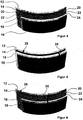
- FIG. 4 A further developed embodiment is in FIG. 4 shown.
- the wall structure (according to Fig. 3 ) to achieve optimum barrier properties against the escape of volatile components (eg., Hydrocarbons, carbon dioxide, flavoring agents o. ⁇ .)
- volatile components eg., Hydrocarbons, carbon dioxide, flavoring agents o. ⁇ .
- the layer 22 of insulating barrier plastic polyamide PA or EVOH
- the two adjacent layers 20 and 24 are made of insulating adhesion promoter (Admer) to obtain a stoffschl mannerige connection between the different plastic materials (HD-PE and polyamide PA or EVOH) otherwise they would not stick together in direct contact without adhesion promoter.
- Admer insulating adhesion promoter
Description
Die vorliegende Erfindung betrifft ein Verfahren zur Herstellung von elektrostatisch nicht aufladbaren oder/und elektrisch ableitenden Kunststoff-Behältern und einen danach hergestellten mehrschichtigen Kunststoff-Behälter zur Lagerung und zum Transport von flüssigen Füllgütern, insbesondere für brennbare oder explosionsgefährliche Füllgüter. Der Kunststoffbehälter kann als Kanister oder Fassett, als geschlossenes Spundfass, als Deckelfass mit Fassdeckel und Spannringverschluss oder als Innenbehälter eines großvolumigen Palettencontainers ausgebildet sein.The present invention relates to a process for the production of electrostatically non-chargeable and / or electrically dissipative plastic containers and a multi-layer plastic container produced thereafter for the storage and transport of liquid products, in particular for flammable or explosive products. The plastic container can be designed as a canister or Fassett, as a closed bunged barrel, as a lidded barrel with barrel lid and clamping ring closure or as an inner container of a large-volume pallet container.
Im Markt bekannt und für den Einsatz in Explosionsschutzzonen oder zur Befüllung mit brennbaren Füllgütern in Anwendung befindliche Systeme sind z. B. Palettenbehälter mit einem im Mehrschichtverfahren hergestellten Innenbehälter aus Kunststoff mit einer leitfähigen oder/und permanent antistatischen Außenschicht bei welchem die Erdung des Füllguts über entsprechende Maßnahmen im Bodenbereich des Behälters, wie z. B. den Einsatz von Metallschrauben oder von leitfähigen Kunststoffen an der Auslaufarmatur erfolgt. Die entsprechenden Innenbehälter aus Kunststoff werden vornehmlich im 3-Schicht oder 6-Schicht Coextrusions-Verfahren hergestellt und weisen eine Gesamtwanddicke von ca. 2 - 3 mm auf. Die nach Abzug der leitfähigen bzw. permanent antistatischen Außenschicht verbleibende isolierende Restwandstärke liegt dabei unterhalb von 2 mm.Known in the market and for use in explosion protection zones or for filling with combustible products in use systems are for. B. pallet container with a manufactured in multi-layer process inner container made of plastic with a conductive and / or permanent antistatic outer layer in which the grounding of the filling material via appropriate measures in the bottom region of the container, such. B. the use of metal screws or conductive plastics on the outlet fitting. The corresponding inner containers made of plastic are mainly produced in 3-layer or 6-layer coextrusion process and have a total wall thickness of about 2 - 3 mm. The remaining residual wall thickness remaining after deduction of the conductive or permanently antistatic outer layer is less than 2 mm.
Im Bereich der Elektrik/Elektronik wird in der einschlägigen Fachliteratur und Normung (z. B. CENELEC TR 50404 Seite 10) eine Wandstärke isolierenden Materials von kleiner gleich 2 mm in Verbindung mit einem fest verbundenen elektrischen Leiter als ausreichend sicher angesehen, Aufladungen der gegenüberliegenden Oberfläche des Isolators zu vermeiden, welche bei entsprechender Entladung Füllgüter und Gase der Explosionsgruppen Gruppe IIA und IIB entzünden würden.In the field of electrics / electronics, in the relevant specialist literature and standardization (eg CENELEC TR 50404 page 10), a wall thickness of insulating material of less than or equal to 2 mm in conjunction with a permanently connected electrical conductor is considered sufficiently safe, charging the opposite surface of the insulator, which would ignite products and gases of explosion groups group IIA and IIB if discharged accordingly.
Die für den Einsatz in Explosionsschutzzonen bzw. die Befüllung mit entflammbaren Füllgütern konzipierten und im Einsatz befindlichen freitragenden Kunststoffgebinde, wie z. B. Fässer oder Kanister, werden ebenfalls vornehmlich im Mehrschichtverfahren hergestellt und zeichnen sich durch die Verwendung eines leitfähigen oder/und permanent antistatischen Kunststoffmaterials in der Außenschicht aus. In der
Aus dem Dokument
Der vorliegenden Erfindung liegt die Aufgabe zugrunde, einen mehrschichtigen Kunststoffbehälter für den Einsatz in Explosionsschutzzonen und eine Befüllung mit brennbaren Füllgütern der Explosionsgruppe IIA und IIB derart weiter zu entwickeln, dass seine elektrostatische Eignung und eine verbesserte mechanische Festigkeit (Stabilität) unter Berücksichtigung einer guten Wirtschaftlichkeit auch bei dickwandigeren Behältern, d. h. bei Wandstärken größer 2 mm, gegeben ist.The present invention has for its object to further develop a multilayer plastic container for use in explosion protection zones and a filling with combustible products of the explosion group IIA and IIB, that its electrostatic suitability and improved mechanical strength (stability), taking into account a good economy also in thick-walled containers, ie given wall thicknesses greater than 2 mm, is given.
Der erfindungsgemäße Kunststoff-Behälter wird als Mehrschichtbehälter vorzugsweise im Extrusionsblasformverfahren hergestellt und umfasst mindestens eine in die Wandung des Behälterkörpers integrierte (innenliegende, eingebettete) Schicht aus elektrisch leitendem Kunststoffmaterial, welche die verbleibende Restwandung in wenigstens zwei isolierende Kunststoffschichten mit Schichtdicken von jeweils kleiner als 2,5 mm unterteilt. Das verwendete Kunststoffmaterial dieser Schichten besteht aus HDPE-Kunststoff (High Density Poly Ethylen).
Es hat sich herausgestellt, dass bei einem derartigen Grundaufbau eine elektrostatische Aufladung der inneren Oberfläche der mit dem Füllgut in Berührung stehenden HDPE-Kunststoffschicht nicht oder nur in ganz geringem Maße erfolgt, wenn diese innenseitige, isolierende und nicht leitende Kunststoffschicht eine Schichtdicke von weniger als 2,5 mm bzw. 2 mm aufweist. Dadurch, daß hinter der auf der Behälterinnenseite angeordneten isolierenden Schicht großflächig eine elektrisch sehr gut leitende Kunststoffschicht angeordnet ist, werden entstehende elektrische Ladungen auf kürzestem Wege (kleiner gleich 2,5 mm) durch die an sich isolierende Kunststoffschicht hindurchtransportiert und von der direkt dahinter angeordneten elektrisch leitenden Schicht sozusagen "aufgesogen". Wenn die elektrisch leitende Kunststoffschicht genügend elektrische Ladung aufgenommen hat und eine ausreichend hohe Ladungsträgerkonzentration erreicht ist, werden diese Ladungsträger über die äußere isolierende Kunststoffschicht mit einer Schichtdicke von weniger als 2,5 mm bzw. 2 mm über eine elektrisch ableitende Standfläche des Kunststoffbehälters auf einfache Weise in den Boden abgeleitet.
Bei der erfindungsgemäßen Behälterwandung werden die negativ geladenen Elektronen/Ladungsträger, die eine elektrische Aufladung der inneren Oberfläche des Kunststoffbehälters bewirken, aufgrund der großflächigen Kontakt-/Berührungsfläche der beiden Schichten in Radialrichtung über eine sehr kurze Distanz (kleiner/gleich 2,5 mm) durch die aus HDPE-Neumaterial bestehende Schicht hindurchgesogen und von dem elektrischen Leiter aufgenommen und dort angesammelt. Das Ladungsgefälle von innen (hoch) nach außen (niedrig) bewirkt das Abwandern der Ladungsträger durch die "isolierende Schicht" radial nach außen. Die elektrisch leitende Eigenschaft der elektrisch leitenden Kunststoffschicht wird durch Zumischen von Leitruß-Compounds eingestellt. Da Leitruß sehr teuer ist, wird die elektrisch leitende Kunststoffschicht in aller Regel nur sehr dünn ausgebildet (kleiner/gleich 5% der Gesamtwandstärke).The plastic container according to the invention is produced as a multilayer container, preferably by extrusion blow molding, and comprises at least one layer of electrically conductive plastic material integrated into the wall of the container body, which deposits the remaining wall in at least two insulating plastic layers with layer thicknesses of less than 2, 5 mm divided. The plastic material used for these layers consists of HDPE plastic (high density poly ethylene).
It has been found that in such a basic structure, an electrostatic charge of the inner surface of the HDPE plastic layer in contact with the medium is not or only in very slight extent occurs when this inside, insulating and non-conductive plastic layer has a layer thickness of less than 2.5 mm or 2 mm. Characterized in that behind the arranged on the inside of the container insulating layer a very good electrically conductive plastic layer is arranged over a large area, resulting electric charges are transported by the shortest path (less than or equal to 2.5 mm) through the insulating layer per se and electrically arranged directly behind the conductive layer, so to speak, "absorbed". If the electrically conductive plastic layer has absorbed enough electrical charge and a sufficiently high charge carrier concentration has been reached, these charge carriers easily pass through the outer insulating plastic layer with a layer thickness of less than 2.5 mm or 2 mm via an electrically dissipating support surface of the plastic container derived in the soil.
In the case of the container wall according to the invention, the negatively charged electrons / charge carriers, which cause electrical charging of the inner surface of the plastic container, due to the large-area contact / contact surface of the two layers in the radial direction over a very short distance (less than or equal to 2.5 mm) the layer consisting of HDPE new material is sucked through and taken up by the electrical conductor and accumulated there. The charge gradient from the inside (high) to the outside (low) causes the charge carriers to migrate radially outward through the "insulating layer". The electrically conductive property of the electrically conductive plastic layer is adjusted by admixing Leitruß compounds. Since Leitruß is very expensive, the electrically conductive plastic layer is usually formed only very thin (less than / equal to 5% of the total wall thickness).
Da der erfindungsgemäße Kunststoff-Behälter für empfindliche und teure Chemikalien verwendet werden soll, ist es zweckmäßig, daß die mit dem flüssigen Füllgut in Berührung kommende innerste Schicht aus HDPE-Neumaterial (virgin material) besteht und die zweite, von der innersten Neumaterial-Schicht abgedeckte integrierte HDPE-Schicht durch entsprechende Zusätze (wie z. B. Leitruß) elektrisch leitfähig ausgebildet ist, wobei diese elektrisch leitfähige Schicht nach außen hin von wenigstens einer weiteren elektrisch nicht leitfähigen bzw. isolierenden HDPE-Schicht überdeckt ist. Bei einem Einsatz für hochsensible hochreine Flüssigkeiten für die Elektronikindustrie kann die mit diesem Füllgut in Kontakt kommende Materialschicht aus einem besonders reinen Kunststoffrohstöff bestehen, der völlig frei von jeglichen Verunreinigungen wie Katalysatoren und Stabilisatoren bzw. schädlichen Metallionen etc. ist und somit die hohen Reinheitsanforderungen für die besonderen Füllgüter erfüllt. Als Verunreinigungen des hochreinen Kunststoffmaterials werden hierbei insbesondere Katalysatorrückstände (catalyst residues), Füllmaterial (fillers), Stabilisierungszusätze (stabilizers), Antioxidantien (antioxidants), Weichmacher/Plastizierungsmittel (plastizers) oder Pozeßhilfsmittel (process aids), z. B. Stearate (stearates) usw. angesehen.Since the plastic container according to the invention is to be used for sensitive and expensive chemicals, it is expedient that the innermost layer coming into contact with the liquid filling material consists of virgin material and the second layer covered by the innermost layer of new material integrated HDPE layer by appropriate additives (such as Leitruß) is electrically conductive, said electrically conductive layer is covered to the outside of at least one further electrically non-conductive or insulating HDPE layer. When used for highly sensitive high-purity liquids for the electronics industry, the material layer coming into contact with this product may consist of a particularly pure Kunststoffrohstöff that is completely free of any impurities such as catalysts and stabilizers or harmful metal ions, etc., and thus the high purity requirements for filled special products. As impurities of the high-purity plastic material in this case, in particular catalyst residues (catalyst residues), filler (fillers), stabilizing additives (stabilizers), antioxidants, plasticizers / plasticizers or process aids, e.g. As stearates (stearates), etc. viewed.
Die weitere, elektrisch nicht leitfähige bzw. isolierende HDPE-Schicht ist von einem schmalen vertikal verlaufenden Kunststoffstreifen aus elektrisch leitendem Kunststoffmaterial - nach Art eines Sichtstreifens - unterbrochen, der - in Radialrichtung betrachtet - nur die Stärke der weiteren, elektrisch nicht leitfähigen bzw. isolierenden HDPE-Schicht aufweist und mit der integrierten, elektrisch leitfähigen HDPE-Schicht in formschlüssiger und elektrisch leitender Verbindung steht. Hierbei weist der Kunststoff-Behälter weiterhin eine ununterbrochene, d. h. durchgehende innere Schicht aus HDPE-Neumaterial auf, die bei Bedarf möglichst dünn ausgestaltet ist und eine Wandstärke von nur 0,5 - 1 mm aufweist, so dass elektrische Ladungen gut "hindurchgesaugt" und von der "inneren" integrierten elektrisch leitfähigen Kunststoffschicht aufgenommen werden können. Diese integrierte elektrisch leitende Kunststoffschicht steht nun zur Weiterleitung der abgesaugten elektrischen Ladungen über den schmalen vertikal verlaufenden Kontakt-Streifen aus elektrisch leitendem Kunststoffmaterial, der verfahrenstechnisch nach Art eines bekannten Sichtstreifens in die äußere, elektrisch nicht leitfähige bzw. isolierende HDPE-Schicht eingebracht ist und im Bodenbereich des Behälters bis an die Trennnaht verläuft, in sehr guter elektrisch leitender Verbindung mit einer elektrisch ableitenden Standfläche des Kunststoffbehälters.
Um die elektrische Ableitfähigkeit des Behälters weiter zu verbessern, weist dieser in einem weiteren Ausführungsbeispiel einen vierschichtigen Wandungsaufbau auf, wobei die vierte Kunststoff-Schicht die bisherigen drei Schichten von außen überdeckt und ebenfalls aus elektrisch leitendem HDPE-Kunststoffmaterial besteht. Dadurch werden elektrische Ladungen, die sich in der integrierten (eingebetteten) elektrisch leitenden Kunststoffschicht angesammelt haben, ebenfalls großflächig durch die dritte, aus nicht leitendem Kunststoffmaterial bestehende Schicht hindurchgesaugt und über die äußere elektrisch leitende Schicht des Kunststoff-Behälters über dessen Standfläche in den Boden abgeleitet. Dabei kann weiterhin vorgesehen sein, dass die dritte, aus nicht leitendem Kunststoffmaterial bestehende Schicht ebenfalls von einem schmalen vertikal verlaufenden Kontakt-Streifen aus elektrisch leitendem Kunststoffmaterial - nach Art eines Sichtstreifens - unterbrochen ist, der- in Radialrichtung betrachtet- nur die Stärke der elektrisch nicht leitfähigen bzw. isolierenden HDPE-Schicht aufweist, und der quasi als Leiter-Brücke dient und die integrierte innere Kunststoffschicht aus elektrisch leitendem Kunststoffmaterial mit der vierten äußeren Schicht aus elektrisch leitendem Kunststoffmaterial in direkte elektrisch leitende Verbindung bringt.The other, electrically non-conductive or insulating HDPE layer is interrupted by a narrow vertically extending plastic strip of electrically conductive plastic material - like a sight strip - the - viewed in the radial direction - only the strength of the other, electrically non-conductive or insulating HDPE Layer and is in positive and electrically conductive connection with the integrated, electrically conductive HDPE layer. Here, the plastic container further has an uninterrupted, ie continuous inner layer of HDPE new material, which is configured as thin as possible and has a wall thickness of only 0.5 - 1 mm, so that electrical charges well "sucked through" and from the "inner" integrated electrically conductive plastic layer can be added. This integrated electrically conductive plastic layer is now for forwarding the sucked electrical charges on the narrow vertical contact strip of electrically conductive plastic material, which is procedurally introduced in the manner of a known Sichtstreifens in the outer, electrically non-conductive or insulating HDPE layer and in Bottom area of the container extends to the cutting seam, in very good electrically conductive connection with an electrically dissipating footprint of the plastic container.
In order to further improve the electrical conductivity of the container, the latter has, in another exemplary embodiment, a four-layer wall structure, wherein the fourth plastic layer covers the previous three layers from the outside and also consists of electrically conductive HDPE plastic material. As a result, electrical charges that have accumulated in the integrated (embedded) electrically conductive plastic layer, also large area sucked through the third, consisting of non-conductive plastic material layer and derived through the outer electrically conductive layer of the plastic container on the floor space in the ground , It may further be provided that the third, consisting of non-conductive plastic material layer is also interrupted by a narrow vertically extending contact strip of electrically conductive plastic material - like a sight strip -, viewed in the radial direction - only the strength of the electrically not has conductive or insulating HDPE layer, and serves as a quasi-conductor bridge and brings the integrated inner plastic layer of electrically conductive plastic material with the fourth outer layer of electrically conductive plastic material in direct electrically conductive connection.
Um ein Ableiten der angesammelten Ladungsträger aus der integrierten inneren elektrisch leitenden Kunststoffschicht zu fördern und zu beschleunigen ist erfindungsgemäß vorgesehen, daß in die äußere, elektrisch leitfähige Kunststoffschicht und die dahinter liegende elektrisch nicht leitfähige bzw. isolierende HDPE-Schicht wenigstens ein schmaler vertikal verlaufender Kunststoffstreifen aus elektrisch leitendem Kunststoffmaterial - eingesetzt ist, der - in Radialrichtung betrachtet - nur die Stärke der beiden Schichten aufweist und mit der innenliegenden integrierten, elektrisch leitfähigen HDPE-Schicht in formschlüssiger und elektrisch leitender Verbindung steht.
Der einteilig (einstückig) im Extrusionsblasformverfahren hergestellte Kunststoffbehälter wird mit mindestens drei Schichten, für besondere Anwendungsfälle auch in vier oder sieben Schichten ausgeführt und zeichnet sich durch folgenden Schichtaufbau aus:
Der entsprechende Schichtenaufbau gewährleistet, daß die maximal auftretende Schichtdicke der isolierenden Kunststoffschichten in der Gesamtwandung unterhalb der Stärke von 2,5 mm liegt und somit eine kritische elektrische Aufladung freiliegender isolierender Oberflächen ausgeschlossen ist. Der Verbrauch des kostenintensiven leitfähigen Kunststoffmaterials wird durch die möglichst dünne Ausführung der entsprechenden Schichten reduziert. Dabei verhalten sich die sehr dünnen Schichten aus leitfähigen Kunststoffmaterial wesentlich flexibler als eine dicke, sprödbruchempfindliche Kunststoffschicht mit Leitruß an der Außenseite eines entsprechenden Behälters, so daß dadurch die Kältefallfestigkeit erheblich verbessert wird. Hierzu sei angemerkt, daß der Zusatz von Leitruß - wie allgemein bekannt ist - die mechanischen Eigenschaften von elektrisch leitenden Kunststoffen erheblich verschlechtern kann.In order to promote and accelerate the dissipation of the accumulated charge carriers from the integrated inner electrically conductive plastic layer, it is provided according to the invention that at least one narrow vertical plastic strip extends into the outer, electrically conductive plastic layer and the electrically nonconductive or insulating HDPE layer behind it electrically conductive plastic material - is used, which - viewed in the radial direction - has only the strength of the two layers and is in positive and electrically conductive connection with the internal integrated, electrically conductive HDPE layer.
The one-piece (one-piece) produced by extrusion blow molding plastic container is designed with at least three layers, for special applications in four or seven layers and is characterized by the following layer structure:
The corresponding layer structure ensures that the maximum occurring layer thickness of the insulating plastic layers in the overall wall is below the thickness of 2.5 mm and thus a critical electrical charge of exposed insulating surfaces is excluded. Consumption of the costly conductive plastic material is reduced by the thinnest possible design of the corresponding layers. The very thin layers of conductive plastic material behave much more flexible than a thick, brittle fracture-sensitive plastic layer with Leitruß on the outside of a corresponding container, so that thereby the cold resistance is significantly improved. It should be noted that the addition of Leitruß - as is well known - can significantly degrade the mechanical properties of electrically conductive plastics.
Um das potentielle Füllgut im Behälterinneren über eine direkte elektrische Verbindung von der Innenoberfläche zur Außenoberfläche zu erden, kann der erfindungsgemäße Behälter in der Ausführung mit elektrisch leitfähigen Kunststoffschichten darüber hinaus dahingehend ausgeführt werden, daß die isolierenden Kunststoffschichten partiell durch leitfähiges Kunststoffmaterial unterbrochen bzw. überbrückt und somit die leitfähigen Schichten innerhalb der Behälterwandung untereinander leitend verbunden werden. Wesentliches Merkmal dieser lokalen Schichtunterbrechung ist, daß die partielle Unterbrechung einer Schicht nicht in radialer Richtung zur Unterbrechung anderer Schichten oder aller Schichten vollzogen wird, so daß keine, in der gesamten Wandungsstärke ausgeprägte, durchgehende leitfähige Verbindung entsteht. Durch diese vorteilhafte Ausführung wird wiederum gewährleistet, daß mechanische Schwachstellen in Form von durchgängigen Materialanhäufungen (in Radialrichtung wie in Axialrichtung) des spröden leitfähigen Kunststoffs bei ähnlichen heute bekannten Lösungsansätzen (
Die Ausführung der lokal begrenzten leitfähigen Streifen innerhalb der nicht leitfähigen isolierenden Kunststoffschichten der Behälterwandung erfolgt vorzugsweise parallel zur Faßlängsachse in Vertikalrichtung über den Faßkörper und radial über den Unter-/Oberboden des Behälters. Auch andere, z. B. punkt- oder spiralförmige Ausführungen der leitfähigen Kontaktstreifen sind möglich.
Die Anzahl der lokalen leitfähigen Verbindungsstellen ist auf wenigstens eine pro isolierender Schicht festgelegt. Weitere lokale leitfähige Verbindungsstreifen pro Schicht sind ohne weiteres möglich und können je nach verfahrenstechnischer Umsetzung zum Einsatz kommen.In order to ground the potential filling material in the container interior via a direct electrical connection from the inner surface to the outer surface, the container according to the invention in the embodiment with electrically conductive plastic layers can also be carried out to the effect that the insulating plastic layers partially interrupted or bridged by conductive plastic material and thus the conductive layers within the container wall are conductively connected to each other. An essential feature of this local layer interruption is that the partial interruption of a layer is not carried out in the radial direction to interrupt other layers or all layers, so that no, throughout the wall thickness pronounced, continuous conductive connection is formed. This advantageous embodiment in turn ensures that mechanical weak points in the form of continuous accumulations of material (in the radial direction as well as in the axial direction) of the brittle conductive plastic in similar known today solution approaches (
The execution of the locally limited conductive strips within the non-conductive insulating plastic layers of the container wall is preferably carried out parallel to the barrel longitudinal axis in the vertical direction over the barrel body and radially over the lower / upper bottom of the container. Other, z. B. point or spiral versions of the conductive contact strips are possible.
The number of local conductive junctions is set to at least one per insulating layer. Other local conductive connecting strips per layer are readily possible and can be used depending on the process engineering implementation.
Die Position der lokalen leitfähigen Verbindungsstreifen ist - in Umfangsrichtung gesehen - für verschiedene, zueinander versetzt angeordnete Ausführungen in den einzelnen isolierenden Schichten frei wählbar.
Bei der bevorzugten verfahrenstechnischen Ausführung als zur Faßachse parallele bzw. vertikale Streifen in der Behälterwandung ist eine um ca. 10 Grad aus der Formtrennnaht versetzte Positiorierung vorteilhaft. In der entsprechenden Anordnung zueinander sind die beiden lokalen leitfähigen Streifen in den einzelnen Schichten um 180° zueinander versetzt angeordnet.The position of the local conductive connection strips is - as seen in the circumferential direction - freely selectable for different, mutually staggered versions in the individual insulating layers.
In the preferred procedural embodiment as parallel to the barrel axis or vertical strip in the container wall offset by about 10 degrees from the mold parting line positioning is advantageous. In the corresponding arrangement to one another, the two local conductive strips in the individual layers are arranged offset by 180 ° from one another.
Die Erfindung wird nachfolgend anhand von in den Zeichnungen schematisch dargestellten Ausführungsbeispielen näher erläutert und beschrieben. Es zeigen:
- Figur 1
- einen erfindungsgemäßen Kunststoffbehälter als 220 IL-Ringfaß,
- Figur 2
- einen 3-Schicht-Aufbau mit leitfähiger Mittelschicht,
- Figur 3
- einen 4-Schicht-Aufbau mit leitfähiger Mittelschicht,
- Figur 4
- einen erfindungsgemäßen 7-Schicht-Aufbau mit leitfähiger Mittelschicht,
- Figur 5
- einen 4-Schicht-Aufbau mit leitfähiger Mittelschicht und lokalen leitfähigen Streifen in den isolierenden Schichten und
- Figur 6
- einen 7-Schicht-Aufbau mit leitfähiger Mittelschicht und lokalen leitfähigen Streifen in den isolierenden Schichten.
- FIG. 1
- a plastic container according to the invention as 220 IL-ring barrel,
- FIG. 2
- a 3-layer structure with a conductive middle layer,
- FIG. 3
- a 4-layer structure with conductive middle layer,
- FIG. 4
- a 7-layer structure with conductive middle layer according to the invention,
- FIG. 5
- a 4-layer structure with conductive middle layer and local conductive strips in the insulating layers and
- FIG. 6
- a 7-layer structure with conductive middle layer and local conductive strips in the insulating layers.
Der erfindungsgemäße Kunststoffbehälter kann z. B. als Kanister bzw. Fassett, als Spundfaß, als Deckelfaß mit Faßdeckel und Spannringverschluß oder als Innenbehälter eines großvolumigen Palettencontainers ausgebildet sein. In aller Regel weist ein derartiger Kunststoffbehälter vertikal verlaufende Behälterwandungen mit horizontal verlaufendem Behälteroberboden und -unterboden auf, wobei wenigstens im Behälteroberboden bzw. im Behälterdeckel eine gas- und flüssigkeitsdicht verschließbare Einfüll- und Entleerungsöffnung angeordnet ist.
In
Bei einem ersten Ausführungsbeispiel ist das rechteckige Wandungsstück "X" in
Eine besonders bevorzugte Ausführungsform ist in
In
In a first embodiment, the rectangular wall piece "X" in
A particularly preferred embodiment is in
Ein weiter ausgebildete Ausführungsbeispiel ist in
Bei dem in
Im Unterschied zu einem an sich bekannten durchgehenden elektrisch leitenden Verbindungsstreifen, der wie ein Sichtstreifen - in Radialrichtung betrachtet - durch die gesamte Wandung hindurchgeht, erstrecken sich die beiden Streifen 26, 28 in Radialrichtung betrachtet jeweils nur partiell bzw. nicht vollständig durchgehend in der Wandung des jeweiligen Behälters. Zudem sind die beiden Streifen 26 und 28 auch seitlich voneinander beabstandet und an verschiedenen Umfangspositionen des Kunststoffbehälters versetzt zueinander angeordnet.
Schließlich ist diese Verfahrensvariante mit den wenigstens zwei in Vertikalrichtung verlaufenden und in Umfangsrichtung voneinander beabstandeten Kontakt-Streifen auch für einen Kunststoffbehälter mit siebenschichtigem Wandungsaufbau realisiert, wie in
At the in
In contrast to a per se known continuous electrically conductive connecting strip, which like a viewing strip - viewed in the radial direction - passes through the entire wall, the two
Finally, this method variant is realized with the at least two vertically extending and circumferentially spaced contact strips for a plastic container with seven-layer wall structure, as in
In Kombination mit ebenfalls in die verbleibenden isolierenden Restschichten integrierten lokalen Abschnitten aus leitfähigem Kunststoffmaterial kann also bei Bedarf eine elektrische Verbindung zwischen Innen- und Außenoberfläche des Behälters ausgebildet werden. Die Stärke der einzelnen lokalen Verbindung ist hierbei - in Radialrichtung betrachtet - kleiner als die Gesamtwandstärke des Behälters.
Durch die vorteilhafte Vermeidung von voll durchgehenden Streifen aus elektrisch leitendem Kunststoffmaterial wird die sonst in Kauf zu nehmende Verschlechterung der Kältefallfestigkeit stark vermindert.In combination with local sections of conductive plastic material which are likewise integrated into the remaining insulating residual layers, an electrical connection can therefore be formed between the inner and outer surfaces of the container if required. The strength of the individual local connection here is - viewed in the radial direction - smaller than the total wall thickness of the container.
Due to the advantageous avoidance of fully continuous strips of electrically conductive plastic material, the deterioration of the cold resistance that would otherwise be tolerated is greatly reduced.
Verfahrenstechnisch kennzeichnet sich die vorliegende Erfindung dadurch aus, daß aus wenigstens drei Extrudern drei verschiedene Kunststoffmaterialien in einen Umfangsverteiler eingefördert und darin zu einem wenigstens dreischichtigen schlauchförmigen Vorformling umgeformt werden, wobei die Innenschicht aus einem elektrisch nicht leitenden Kunststoffmaterial (HDPE-Neuware), die von der Innenschicht abgedeckte integrierte Schicht aus einem elektrisch leitenden Kunststoffmaterial (z. B. HDPE mit Leitrußzüsatz) und eine weitere äußere Schicht wiederum aus einem elektrisch nicht leitenden Kunststoffmaterial (HDPE) besteht, und wobei dieser schlauchförmige Vorformling in üblicher Weise in einer entsprechenden Blasform mittels Pressluft zu einem Kunststoff-Hohlkörper aufgeblasen wird. Der Umfangsverteiler ist zusätzlich mit geeigneten Mitteln versehen, um an gewünschter Stelle die Kontaktstreifen aus elektrisch leitendem Kunststoffmaterial in die innenseitigen oder/und außenseitigen Schichten aus elektrisch nicht leitfähigem Kunststoffmaterial einzubringen.Technically, the present invention is characterized in that from at least three extruders three different plastic materials are conveyed into a peripheral distributor and formed into an at least three-layer tubular preform, wherein the inner layer of an electrically non-conductive plastic material (HDPE virgin), the Inner layer covered integrated layer of an electrically conductive plastic material (eg HDPE with Leitrußzüsatz) and another outer layer in turn of an electrically non-conductive plastic material (HDPE) consists, and wherein this tubular preform in the usual manner in a corresponding blow mold by means of compressed air a plastic hollow body is inflated. The peripheral distributor is additionally provided with suitable means for introducing the contact strips of electrically conductive plastic material into the inside and / or outside layers of electrically non-conductive plastic material at the desired location.
- 1010
- 220 Liter Kunststoff-Spundfaß220 liter plastic bung barrel
- 1212
- innere HDPE-Neuware-SchichtInner HDPE virgin layer
- 1414
- dünne elektrisch leitende Schichtthin electrically conductive layer
- 1616
- isolierende bzw. elektrisch nicht-leitende Schichtinsulating or electrically non-conductive layer
- 1818
- dünne elektrisch leitende Schichtthin electrically conductive layer
- 2020
- isolierender Haftvermittler (Admer)insulating adhesion promoter (Admer)
- 2222
- isolierender Barrierekunststoff (PA oder EVOH)insulating barrier plastic (PA or EVOH)
- 2424
- isolierender Haftvermittler (Admer)insulating adhesion promoter (Admer)
- 2626
- Kontakt-Streifen aus elektrisch leitendem KunststoffContact strip made of electrically conductive plastic
- 2828
- Kontakt-Streifen aus elektrisch leitendem KunststoffContact strip made of electrically conductive plastic
- 3030
- Kontakt-Streifen aus elektrisch leitendem KunststoffContact strip made of electrically conductive plastic
Claims (8)
- Multilayer thermoplastic container for storing and transporting liquid contents, in particular for flammable or explosive contents, which is made of at least three layers and has at least one layer that is durably electrostatically non-chargeable or electrically discharging, wherein a layer (14) integrated into the wall of the container body and made of electrically conductive and/or permanently antistatic HDPE plastic material is provided, which divides the remaining residual wall into at least two insulating HDPE plastic layers (12, 16), with each layer having a thickness of less than 2.5 mm, and wherein the innermost layer (12) coming into contact with the liquid content is made of HDPE virgin material and the second integrated HDPE layer (14), which is covered by the innermost virgin material layer (12), is rendered electrically conductive by suitable additives (e.g., conductive carbon black) with a conductivity for suction of static charges, wherein this electrically conductive layer (14) is covered on the outside by at least one additional electrically non-conductive or insulating HDPE layer (16), characterized in that
the additional, electrically non-conductive or insulating HDPE layer (16) is interrupted by a narrow, vertically extending plastic strip (28) made of electrically conductive plastic material - in the manner of a viewing strip - which - when viewed in the radial direction - has only the thickness of the additional, electrically non-conductive or insulating HDPE layer (16) and has a positive and electrically conductive connection with the integrated, electrically conductive HDPE layer (14). - Plastic container according to claim 1,
characterized by
a four-layer wall construction, wherein the fourth plastic layer (18) externally covers the existing three layers (12, 14, 16) and is also made of electrically conductive HDPE plastic material. - Plastic container according to claim 1 or 2,
characterized in that
the innermost layer (12) made of insulating plastic (HDPE virgin material) and coming into contact with the content has a thickness of less than/equal to 2.5 mm (up to about 45% of the total wall thickness), the integrated electrically conductive plastic layer (14) has a wall thickness of less than/equal to 5% of the total wall thickness, the additional, electrically non-conductive or insulating HDPE layer (16) also has a thickness of less than/equal to 2.5 mm (up to about 45% of the total wall thickness), and the outer, electrically conductive plastic layer (18) also has a wall thickness of less than/equal to 5% of the total wall thickness. - Plastic container according to claim 1,2 or 3,
characterized in that
at least one narrow, vertically extending plastic strip (28) made of electrically conductive plastic material is inserted in the outer, electrically conductive plastic layer (18) and the following, electrically non-conductive or insulating HDPE layer (16), wherein the strip (28) - when viewed in the radial direction - has only the thickness of the two layers (16, 18) and has a positive and electrically conductive connection with the inner integrated, electrically conductive HDPE layer (14). - Plastic container according to claim 1, 2, 3 or 4,
characterized in that
at least one narrow, vertically extending plastic strip (26) made of electrically conductive plastic material is inserted in the innermost layer (12) which is in contact with the content and is made of insulating plastic (HDPE virgin material), wherein the strip (26) - when viewed in the radial direction - has only the thickness of this layer (12) and has a positive and electrically conductive connection with the inner integrated, electrically conductive HDPE layer (14). - Plastic container according to one of the preceding claims 1 to 5,
characterized in that
a so-called "barrier layer" made of polyamide PA or EVOH, optionally two admer/bonding agent layers (20, 22, 24), is arranged between the inner integrated, electrically conductive HDPE layer (14) and the covering electrically non-conductive or insulating HDPE layer (16) (made of virgin material and/or regrind material). - Plastic container according to one of the preceding claims 1 to 6,
characterized in that
the inner integrated, electrically conductive HDPE layer (14) is in conductive connnection with the content disposed in the interior of the container via at least one contact strip (26), which is made of electrically conductive plastic material and which is inserted into the innermost layer (12) made of insulating plastic (HDPE virgin material) and in contact with the content, and the inner integrated, electrically conductive HDPE layer (14) is in electrically conductive connection with the outer electrically conductive plastic layer (18) via at least one additional contact strip (30) inserted into the remaining layers (16, 20, 22, 24) made of non-conductive plastic material (without addition of conductive carbon black) that externally cover the inner integrated, electrically conductive HDPE layer (14). - Method for producing a multilayer plastic container, according to at least one of the preceding claims 1 to 7,
characterized in that
three different plastic materials are supplied from at least three extruders to a peripheral manifold where they are formed into an at least three-layer tubular preform, wherein the inner layer is made of an electrically non-conductive plastic material (HDPE virgin material), the integrated layer covered by the inner layer is made of an electrically conductive plastic material (e.g., HDPE with addition of conductive carbon black) with a conductivity for suction of static charges, and an additional outer layer which is also made of an electrically non-conductive plastic material (HDPE), wherein in this additional outer layer of electrically non-conductive plastic material there is inserted a narrow strip of an electrically conductive plastic material extending in the longitudinal direction, which strip has only the layer thickness of the layer of the electrically non-conductive plastic material,
and wherein this tubular preform is expanded in a corresponding blow mold with compressed air to give a hollow plastic body.
Applications Claiming Priority (2)
| Application Number | Priority Date | Filing Date | Title |
|---|---|---|---|
| DE202006008091 | 2006-05-18 | ||
| PCT/EP2007/004382 WO2007134781A2 (en) | 2006-05-18 | 2007-05-16 | Multilayer plastic container |
Publications (2)
| Publication Number | Publication Date |
|---|---|
| EP2018265A2 EP2018265A2 (en) | 2009-01-28 |
| EP2018265B1 true EP2018265B1 (en) | 2016-04-27 |
Family
ID=38565159
Family Applications (1)
| Application Number | Title | Priority Date | Filing Date |
|---|---|---|---|
| EP07725297.1A Active EP2018265B1 (en) | 2006-05-18 | 2007-05-16 | Multilayer plastic container |
Country Status (16)
| Country | Link |
|---|---|
| US (2) | US20090269530A1 (en) |
| EP (1) | EP2018265B1 (en) |
| JP (1) | JP5124565B2 (en) |
| KR (1) | KR101376627B1 (en) |
| CN (1) | CN101500792B (en) |
| AU (1) | AU2007251935B2 (en) |
| BR (1) | BRPI0712033B1 (en) |
| CA (1) | CA2652580C (en) |
| DE (1) | DE112007001225A5 (en) |
| ES (1) | ES2584835T3 (en) |
| IL (1) | IL195275A (en) |
| MX (1) | MX2008014601A (en) |
| MY (1) | MY149059A (en) |
| SG (1) | SG171642A1 (en) |
| WO (1) | WO2007134781A2 (en) |
| ZA (1) | ZA200809816B (en) |
Families Citing this family (19)
| Publication number | Priority date | Publication date | Assignee | Title |
|---|---|---|---|---|
| CA2652580C (en) * | 2006-05-18 | 2014-12-30 | Mauser-Werke Gmbh | Multilayer plastic container |
| US8151523B2 (en) * | 2007-09-20 | 2012-04-10 | Tom Epple | Electrically conductive swimming pool panel |
| FI124163B (en) * | 2008-06-30 | 2014-04-15 | Uponor Infra Oy | Container |
| JP5577854B2 (en) * | 2010-06-01 | 2014-08-27 | 日油株式会社 | Cylindrical ammunition container |
| JP5577870B2 (en) * | 2010-06-14 | 2014-08-27 | 日油株式会社 | Cylindrical ammunition container |
| JP5584031B2 (en) * | 2010-07-09 | 2014-09-03 | 株式会社ダイセル | Projectile storage container |
| PL220004B1 (en) | 2012-06-04 | 2015-08-31 | Mtb Poland Spółka Z Ograniczoną Odpowiedzialnością | Method for producing orthopedic equipment, especially equipped with a rigid elements to actively stimulate areas of injury |
| JP6156184B2 (en) * | 2014-02-21 | 2017-07-05 | 豊田合成株式会社 | Fuel supply device |
| CN104263262A (en) * | 2014-04-28 | 2015-01-07 | 苏州恒坤精密电子有限公司 | Novel adhesive film |
| BE1022703B1 (en) * | 2015-02-10 | 2016-08-17 | CARDIFF GROUP,naamloze vennootschap | Barrel for CO2-containing drinks and their use |
| USD782771S1 (en) | 2015-04-03 | 2017-03-28 | Geo Plastics | Tight head drum |
| DE102015106960A1 (en) * | 2015-05-05 | 2016-11-10 | Bodo Richter | Method and device for producing large-volume containers with flange by plastic blow molding |
| DE202017100694U1 (en) * | 2017-02-09 | 2018-05-11 | Bodo Richter | Double cask for dangerous goods |
| IT201900014271A1 (en) * | 2019-08-07 | 2021-02-07 | Saipem Spa | UNDERWATER STORAGE TANK |
| CN110548344A (en) * | 2019-09-21 | 2019-12-10 | 苏州科佳环境科技有限公司 | antistatic explosion-proof sintered plate dust remover convenient to maintain |
| CN110949121A (en) * | 2019-11-29 | 2020-04-03 | 安徽江淮汽车集团股份有限公司 | Oil tank and automobile with same |
| USD938128S1 (en) | 2020-01-06 | 2021-12-07 | Geo Plastics | Nestable drum |
| USD1001413S1 (en) | 2020-06-30 | 2023-10-10 | Geo Plastics | Nestable drum |
| US20230065269A1 (en) * | 2021-08-28 | 2023-03-02 | Brenda Droege | Hazardous Containment Vessel |
Family Cites Families (12)
| Publication number | Priority date | Publication date | Assignee | Title |
|---|---|---|---|---|
| US4394703A (en) * | 1981-12-24 | 1983-07-19 | Gte Automatic Electric Labs Inc. | Load protecting arrangement |
| US5124878A (en) * | 1989-02-02 | 1992-06-23 | Teleflex Incorporated | Coated braided hose method |
| EP0461836B1 (en) * | 1990-06-15 | 1995-09-06 | Tonen Chemical Corporation | Multi-layer plastic fuel tank |
| DE19905765A1 (en) * | 1999-02-11 | 2000-08-31 | Riedel De Haen Gmbh | Multi-layer device for storing and transporting chemicals |
| US20030106602A1 (en) * | 2001-12-07 | 2003-06-12 | Hsich Henry S. | Multi-layer assembly for fluid handling and containment systems |
| DE20206435U1 (en) * | 2002-04-23 | 2002-08-08 | Schuetz Gmbh & Co Kgaa | plastic drum |
| EP1497188B1 (en) * | 2002-04-23 | 2005-09-28 | MAUSER-WERKE GmbH & Co. KG | Plastic container |
| DE10242956B4 (en) * | 2002-09-17 | 2004-07-15 | Protechna S.A. | Transport and storage container for liquids and method for manufacturing the plastic inner container of the transport and storage container |
| DE10242955B4 (en) * | 2002-09-17 | 2005-03-10 | Schuetz Gmbh & Co Kgaa | Kunststoffaß and method for producing the barrel |
| EP1675905B1 (en) * | 2003-10-23 | 2018-02-21 | MAUSER-WERKE GmbH | Method for producing electrostatically non-chargeable and/or electrically derivable plastic containers, and plastic containers produced thereby |
| DE102005004548A1 (en) * | 2004-03-11 | 2005-12-22 | Schütz GmbH & Co. KGaA | Process for the production of wide-mouth drums of thermoplastic material |
| CA2652580C (en) * | 2006-05-18 | 2014-12-30 | Mauser-Werke Gmbh | Multilayer plastic container |
-
2007
- 2007-05-16 CA CA2652580A patent/CA2652580C/en active Active
- 2007-05-16 CN CN200780018010.6A patent/CN101500792B/en active Active
- 2007-05-16 DE DE112007001225T patent/DE112007001225A5/en not_active Withdrawn
- 2007-05-16 US US12/301,147 patent/US20090269530A1/en not_active Abandoned
- 2007-05-16 MX MX2008014601A patent/MX2008014601A/en active IP Right Grant
- 2007-05-16 AU AU2007251935A patent/AU2007251935B2/en active Active
- 2007-05-16 EP EP07725297.1A patent/EP2018265B1/en active Active
- 2007-05-16 BR BRPI0712033-8A patent/BRPI0712033B1/en active IP Right Grant
- 2007-05-16 MY MYPI20084635A patent/MY149059A/en unknown
- 2007-05-16 KR KR1020087030726A patent/KR101376627B1/en active IP Right Grant
- 2007-05-16 ES ES07725297.1T patent/ES2584835T3/en active Active
- 2007-05-16 WO PCT/EP2007/004382 patent/WO2007134781A2/en active Application Filing
- 2007-05-16 SG SG201103101-0A patent/SG171642A1/en unknown
- 2007-05-16 JP JP2009510352A patent/JP5124565B2/en active Active
-
2008
- 2008-11-13 IL IL195275A patent/IL195275A/en active IP Right Grant
- 2008-11-18 ZA ZA2008/09816A patent/ZA200809816B/en unknown
-
2012
- 2012-03-02 US US13/411,088 patent/US8383219B2/en active Active
Non-Patent Citations (1)
| Title |
|---|
| None * |
Also Published As
| Publication number | Publication date |
|---|---|
| CA2652580A1 (en) | 2007-11-29 |
| ZA200809816B (en) | 2010-02-24 |
| CA2652580C (en) | 2014-12-30 |
| KR20090029720A (en) | 2009-03-23 |
| AU2007251935B2 (en) | 2011-10-06 |
| US20090269530A1 (en) | 2009-10-29 |
| SG171642A1 (en) | 2011-06-29 |
| WO2007134781A2 (en) | 2007-11-29 |
| US8383219B2 (en) | 2013-02-26 |
| JP2009537402A (en) | 2009-10-29 |
| CN101500792B (en) | 2014-03-05 |
| IL195275A0 (en) | 2009-08-03 |
| IL195275A (en) | 2014-11-30 |
| MX2008014601A (en) | 2008-11-28 |
| CN101500792A (en) | 2009-08-05 |
| BRPI0712033A2 (en) | 2011-12-20 |
| AU2007251935A1 (en) | 2007-11-29 |
| JP5124565B2 (en) | 2013-01-23 |
| EP2018265A2 (en) | 2009-01-28 |
| WO2007134781A3 (en) | 2008-01-17 |
| KR101376627B1 (en) | 2014-03-19 |
| ES2584835T3 (en) | 2016-09-29 |
| DE112007001225A5 (en) | 2009-04-23 |
| BRPI0712033B1 (en) | 2018-01-23 |
| MY149059A (en) | 2013-07-15 |
| US20120160729A1 (en) | 2012-06-28 |
Similar Documents
| Publication | Publication Date | Title |
|---|---|---|
| EP2018265B1 (en) | Multilayer plastic container | |
| EP2298549B1 (en) | Multilayer sheet- or tube-shaped food casing or food film | |
| EP2283730B1 (en) | Multi-layer flat or hose-shaped foodstuff container or film | |
| EP1857271B1 (en) | Multilayer planar or tubular food film | |
| DE60124410T2 (en) | CONTAINER OF PLASTIC WITH A CARBONATED INTERIOR SURFACE FOR FOOD WITHOUT CARBONIC ACID | |
| EP1675905B1 (en) | Method for producing electrostatically non-chargeable and/or electrically derivable plastic containers, and plastic containers produced thereby | |
| EP1159131B1 (en) | Multilayer device for storing and transporting chemicals | |
| EP2188104B1 (en) | Method and device for the production of plastic containers | |
| EP1401071A2 (en) | Thermoplastic drum and its method of manufacturing | |
| EP1885542A2 (en) | Extrusion storage head, method for production of blow-moulded multi-layer plastic hollow bodies and corresponding plastic hollow bodies | |
| WO2001068480A1 (en) | Blow moulded containers and moulded parts consisting of synthetic material and having improved antistatic properties | |
| DE3511801C2 (en) | ||
| EP1261523A2 (en) | Multi-shell device for storing and transporting chemicals | |
| DE202006020793U1 (en) | pallet container | |
| EP2181935B1 (en) | Method of manufacturing an anti-static container | |
| DE10301217A1 (en) | Container arrangement for the transport and storage of flammable, flowable substances and process for its manufacture | |
| DE202006011631U1 (en) | Plastic canister for liquids, comprises a permanent antistatic outer layer, an inner surface, and at least one section embedded in the plastic |
Legal Events
| Date | Code | Title | Description |
|---|---|---|---|
| PUAI | Public reference made under article 153(3) epc to a published international application that has entered the european phase |
Free format text: ORIGINAL CODE: 0009012 |
|
| 17P | Request for examination filed |
Effective date: 20081115 |
|
| AK | Designated contracting states |
Kind code of ref document: A2 Designated state(s): AT BE BG CH CY CZ DE DK EE ES FI FR GB GR HU IE IS IT LI LT LU LV MC MT NL PL PT RO SE SI SK TR |
|
| AX | Request for extension of the european patent |
Extension state: AL BA HR MK RS |
|
| DAX | Request for extension of the european patent (deleted) | ||
| 17Q | First examination report despatched |
Effective date: 20091126 |
|
| REG | Reference to a national code |
Ref country code: DE Ref legal event code: R079 Ref document number: 502007014762 Country of ref document: DE Free format text: PREVIOUS MAIN CLASS: B32B0003080000 Ipc: B32B0001020000 |
|
| GRAP | Despatch of communication of intention to grant a patent |
Free format text: ORIGINAL CODE: EPIDOSNIGR1 |
|
| RIC1 | Information provided on ipc code assigned before grant |
Ipc: B32B 27/30 20060101ALI20150908BHEP Ipc: B32B 27/08 20060101ALI20150908BHEP Ipc: B32B 27/34 20060101ALI20150908BHEP Ipc: B32B 1/02 20060101AFI20150908BHEP Ipc: B65D 25/14 20060101ALI20150908BHEP Ipc: F42B 39/00 20060101ALI20150908BHEP Ipc: B32B 27/32 20060101ALI20150908BHEP Ipc: F42B 39/14 20060101ALI20150908BHEP Ipc: B32B 3/08 20060101ALI20150908BHEP |
|
| INTG | Intention to grant announced |
Effective date: 20150922 |
|
| GRAP | Despatch of communication of intention to grant a patent |
Free format text: ORIGINAL CODE: EPIDOSNIGR1 |
|
| GRAS | Grant fee paid |
Free format text: ORIGINAL CODE: EPIDOSNIGR3 |
|
| INTG | Intention to grant announced |
Effective date: 20160226 |
|
| GRAA | (expected) grant |
Free format text: ORIGINAL CODE: 0009210 |
|
| AK | Designated contracting states |
Kind code of ref document: B1 Designated state(s): AT BE BG CH CY CZ DE DK EE ES FI FR GB GR HU IE IS IT LI LT LU LV MC MT NL PL PT RO SE SI SK TR |
|
| REG | Reference to a national code |
Ref country code: GB Ref legal event code: FG4D Free format text: NOT ENGLISH |
|
| REG | Reference to a national code |
Ref country code: CH Ref legal event code: EP |
|
| REG | Reference to a national code |
Ref country code: FR Ref legal event code: PLFP Year of fee payment: 10 |
|
| REG | Reference to a national code |
Ref country code: AT Ref legal event code: REF Ref document number: 794259 Country of ref document: AT Kind code of ref document: T Effective date: 20160515 |
|
| REG | Reference to a national code |
Ref country code: IE Ref legal event code: FG4D Free format text: LANGUAGE OF EP DOCUMENT: GERMAN |
|
| REG | Reference to a national code |
Ref country code: DE Ref legal event code: R096 Ref document number: 502007014762 Country of ref document: DE |
|
| REG | Reference to a national code |
Ref country code: NL Ref legal event code: FP |
|
| REG | Reference to a national code |
Ref country code: LT Ref legal event code: MG4D |
|
| REG | Reference to a national code |
Ref country code: ES Ref legal event code: FG2A Ref document number: 2584835 Country of ref document: ES Kind code of ref document: T3 Effective date: 20160929 |
|
| PG25 | Lapsed in a contracting state [announced via postgrant information from national office to epo] |
Ref country code: PL Free format text: LAPSE BECAUSE OF FAILURE TO SUBMIT A TRANSLATION OF THE DESCRIPTION OR TO PAY THE FEE WITHIN THE PRESCRIBED TIME-LIMIT Effective date: 20160427 Ref country code: LT Free format text: LAPSE BECAUSE OF FAILURE TO SUBMIT A TRANSLATION OF THE DESCRIPTION OR TO PAY THE FEE WITHIN THE PRESCRIBED TIME-LIMIT Effective date: 20160427 Ref country code: FI Free format text: LAPSE BECAUSE OF FAILURE TO SUBMIT A TRANSLATION OF THE DESCRIPTION OR TO PAY THE FEE WITHIN THE PRESCRIBED TIME-LIMIT Effective date: 20160427 |
|
| PG25 | Lapsed in a contracting state [announced via postgrant information from national office to epo] |
Ref country code: SE Free format text: LAPSE BECAUSE OF FAILURE TO SUBMIT A TRANSLATION OF THE DESCRIPTION OR TO PAY THE FEE WITHIN THE PRESCRIBED TIME-LIMIT Effective date: 20160427 Ref country code: PT Free format text: LAPSE BECAUSE OF FAILURE TO SUBMIT A TRANSLATION OF THE DESCRIPTION OR TO PAY THE FEE WITHIN THE PRESCRIBED TIME-LIMIT Effective date: 20160829 Ref country code: GR Free format text: LAPSE BECAUSE OF FAILURE TO SUBMIT A TRANSLATION OF THE DESCRIPTION OR TO PAY THE FEE WITHIN THE PRESCRIBED TIME-LIMIT Effective date: 20160728 Ref country code: LV Free format text: LAPSE BECAUSE OF FAILURE TO SUBMIT A TRANSLATION OF THE DESCRIPTION OR TO PAY THE FEE WITHIN THE PRESCRIBED TIME-LIMIT Effective date: 20160427 |
|
| REG | Reference to a national code |
Ref country code: CH Ref legal event code: PL |
|
| REG | Reference to a national code |
Ref country code: DE Ref legal event code: R097 Ref document number: 502007014762 Country of ref document: DE |
|
| PG25 | Lapsed in a contracting state [announced via postgrant information from national office to epo] |
Ref country code: CZ Free format text: LAPSE BECAUSE OF FAILURE TO SUBMIT A TRANSLATION OF THE DESCRIPTION OR TO PAY THE FEE WITHIN THE PRESCRIBED TIME-LIMIT Effective date: 20160427 Ref country code: RO Free format text: LAPSE BECAUSE OF FAILURE TO SUBMIT A TRANSLATION OF THE DESCRIPTION OR TO PAY THE FEE WITHIN THE PRESCRIBED TIME-LIMIT Effective date: 20160427 Ref country code: CH Free format text: LAPSE BECAUSE OF NON-PAYMENT OF DUE FEES Effective date: 20160531 Ref country code: LI Free format text: LAPSE BECAUSE OF NON-PAYMENT OF DUE FEES Effective date: 20160531 Ref country code: MC Free format text: LAPSE BECAUSE OF FAILURE TO SUBMIT A TRANSLATION OF THE DESCRIPTION OR TO PAY THE FEE WITHIN THE PRESCRIBED TIME-LIMIT Effective date: 20160427 Ref country code: DK Free format text: LAPSE BECAUSE OF FAILURE TO SUBMIT A TRANSLATION OF THE DESCRIPTION OR TO PAY THE FEE WITHIN THE PRESCRIBED TIME-LIMIT Effective date: 20160427 Ref country code: SK Free format text: LAPSE BECAUSE OF FAILURE TO SUBMIT A TRANSLATION OF THE DESCRIPTION OR TO PAY THE FEE WITHIN THE PRESCRIBED TIME-LIMIT Effective date: 20160427 Ref country code: EE Free format text: LAPSE BECAUSE OF FAILURE TO SUBMIT A TRANSLATION OF THE DESCRIPTION OR TO PAY THE FEE WITHIN THE PRESCRIBED TIME-LIMIT Effective date: 20160427 |
|
| REG | Reference to a national code |
Ref country code: IE Ref legal event code: MM4A |
|
| PLBE | No opposition filed within time limit |
Free format text: ORIGINAL CODE: 0009261 |
|
| STAA | Information on the status of an ep patent application or granted ep patent |
Free format text: STATUS: NO OPPOSITION FILED WITHIN TIME LIMIT |
|
| 26N | No opposition filed |
Effective date: 20170130 |
|
| REG | Reference to a national code |
Ref country code: FR Ref legal event code: PLFP Year of fee payment: 11 |
|
| PG25 | Lapsed in a contracting state [announced via postgrant information from national office to epo] |
Ref country code: IE Free format text: LAPSE BECAUSE OF NON-PAYMENT OF DUE FEES Effective date: 20160516 Ref country code: SI Free format text: LAPSE BECAUSE OF FAILURE TO SUBMIT A TRANSLATION OF THE DESCRIPTION OR TO PAY THE FEE WITHIN THE PRESCRIBED TIME-LIMIT Effective date: 20160427 |
|
| REG | Reference to a national code |
Ref country code: AT Ref legal event code: MM01 Ref document number: 794259 Country of ref document: AT Kind code of ref document: T Effective date: 20160516 |
|
| PG25 | Lapsed in a contracting state [announced via postgrant information from national office to epo] |
Ref country code: AT Free format text: LAPSE BECAUSE OF NON-PAYMENT OF DUE FEES Effective date: 20160516 |
|
| REG | Reference to a national code |
Ref country code: FR Ref legal event code: PLFP Year of fee payment: 12 |
|
| PG25 | Lapsed in a contracting state [announced via postgrant information from national office to epo] |
Ref country code: CY Free format text: LAPSE BECAUSE OF FAILURE TO SUBMIT A TRANSLATION OF THE DESCRIPTION OR TO PAY THE FEE WITHIN THE PRESCRIBED TIME-LIMIT Effective date: 20160427 Ref country code: HU Free format text: LAPSE BECAUSE OF FAILURE TO SUBMIT A TRANSLATION OF THE DESCRIPTION OR TO PAY THE FEE WITHIN THE PRESCRIBED TIME-LIMIT; INVALID AB INITIO Effective date: 20070516 |
|
| PG25 | Lapsed in a contracting state [announced via postgrant information from national office to epo] |
Ref country code: MT Free format text: LAPSE BECAUSE OF FAILURE TO SUBMIT A TRANSLATION OF THE DESCRIPTION OR TO PAY THE FEE WITHIN THE PRESCRIBED TIME-LIMIT Effective date: 20160427 Ref country code: TR Free format text: LAPSE BECAUSE OF FAILURE TO SUBMIT A TRANSLATION OF THE DESCRIPTION OR TO PAY THE FEE WITHIN THE PRESCRIBED TIME-LIMIT Effective date: 20160427 Ref country code: IS Free format text: LAPSE BECAUSE OF FAILURE TO SUBMIT A TRANSLATION OF THE DESCRIPTION OR TO PAY THE FEE WITHIN THE PRESCRIBED TIME-LIMIT Effective date: 20160427 |
|
| PG25 | Lapsed in a contracting state [announced via postgrant information from national office to epo] |
Ref country code: BG Free format text: LAPSE BECAUSE OF FAILURE TO SUBMIT A TRANSLATION OF THE DESCRIPTION OR TO PAY THE FEE WITHIN THE PRESCRIBED TIME-LIMIT Effective date: 20160427 |
|
| P01 | Opt-out of the competence of the unified patent court (upc) registered |
Effective date: 20230529 |
|
| PGFP | Annual fee paid to national office [announced via postgrant information from national office to epo] |
Ref country code: NL Payment date: 20230612 Year of fee payment: 17 Ref country code: FR Payment date: 20230612 Year of fee payment: 17 Ref country code: ES Payment date: 20230612 Year of fee payment: 17 Ref country code: DE Payment date: 20230615 Year of fee payment: 17 |
|
| PGFP | Annual fee paid to national office [announced via postgrant information from national office to epo] |
Ref country code: LU Payment date: 20230612 Year of fee payment: 17 |
|
| PGFP | Annual fee paid to national office [announced via postgrant information from national office to epo] |
Ref country code: BE Payment date: 20230612 Year of fee payment: 17 |
|
| PGFP | Annual fee paid to national office [announced via postgrant information from national office to epo] |
Ref country code: IT Payment date: 20230629 Year of fee payment: 17 Ref country code: GB Payment date: 20230612 Year of fee payment: 17 |
|
| REG | Reference to a national code |
Ref country code: DE Ref legal event code: R079 Ref document number: 502007014762 Country of ref document: DE Free format text: PREVIOUS MAIN CLASS: B32B0001020000 Ipc: B32B0001000000 |