EP2018097B1 - Dispositif pour la protection d'une plante - Google Patents
Dispositif pour la protection d'une plante Download PDFInfo
- Publication number
- EP2018097B1 EP2018097B1 EP07748477.2A EP07748477A EP2018097B1 EP 2018097 B1 EP2018097 B1 EP 2018097B1 EP 07748477 A EP07748477 A EP 07748477A EP 2018097 B1 EP2018097 B1 EP 2018097B1
- Authority
- EP
- European Patent Office
- Prior art keywords
- sheath
- seedling
- protection device
- plant protection
- ipp
- Prior art date
- Legal status (The legal status is an assumption and is not a legal conclusion. Google has not performed a legal analysis and makes no representation as to the accuracy of the status listed.)
- Active
Links
- 230000004224 protection Effects 0.000 title claims description 76
- 239000000463 material Substances 0.000 claims description 81
- 238000000354 decomposition reaction Methods 0.000 claims description 31
- 239000011248 coating agent Substances 0.000 claims description 11
- 238000000576 coating method Methods 0.000 claims description 11
- 235000021355 Stearic acid Nutrition 0.000 claims description 8
- QIQXTHQIDYTFRH-UHFFFAOYSA-N octadecanoic acid Chemical compound CCCCCCCCCCCCCCCCCC(O)=O QIQXTHQIDYTFRH-UHFFFAOYSA-N 0.000 claims description 8
- OQCDKBAXFALNLD-UHFFFAOYSA-N octadecanoic acid Natural products CCCCCCCC(C)CCCCCCCCC(O)=O OQCDKBAXFALNLD-UHFFFAOYSA-N 0.000 claims description 8
- 239000008117 stearic acid Substances 0.000 claims description 8
- 238000005470 impregnation Methods 0.000 claims description 5
- 229920003043 Cellulose fiber Polymers 0.000 claims description 3
- 229920000642 polymer Polymers 0.000 claims description 3
- 239000002657 fibrous material Substances 0.000 claims 1
- 241000196324 Embryophyta Species 0.000 description 34
- 241000254171 Curculionidae Species 0.000 description 29
- 235000008331 Pinus X rigitaeda Nutrition 0.000 description 29
- 235000011613 Pinus brutia Nutrition 0.000 description 29
- 241000018646 Pinus brutia Species 0.000 description 29
- 238000000034 method Methods 0.000 description 12
- 239000003415 peat Substances 0.000 description 12
- 239000010410 layer Substances 0.000 description 9
- 206010003497 Asphyxia Diseases 0.000 description 8
- 230000008929 regeneration Effects 0.000 description 8
- 238000011069 regeneration method Methods 0.000 description 8
- 230000004888 barrier function Effects 0.000 description 7
- 230000000694 effects Effects 0.000 description 7
- 239000003795 chemical substances by application Substances 0.000 description 6
- 239000002917 insecticide Substances 0.000 description 5
- 230000015572 biosynthetic process Effects 0.000 description 4
- 238000010276 construction Methods 0.000 description 4
- 230000007423 decrease Effects 0.000 description 4
- 239000003292 glue Substances 0.000 description 4
- 238000009304 pastoral farming Methods 0.000 description 4
- 239000002689 soil Substances 0.000 description 4
- 239000000126 substance Substances 0.000 description 4
- 238000004026 adhesive bonding Methods 0.000 description 3
- 238000005520 cutting process Methods 0.000 description 3
- 230000018109 developmental process Effects 0.000 description 3
- 230000008569 process Effects 0.000 description 3
- 230000001681 protective effect Effects 0.000 description 3
- 241000894007 species Species 0.000 description 3
- 238000005507 spraying Methods 0.000 description 3
- 230000005068 transpiration Effects 0.000 description 3
- 241001465180 Botrytis Species 0.000 description 2
- 241001465754 Metazoa Species 0.000 description 2
- 206010003549 asthenia Diseases 0.000 description 2
- 230000007123 defense Effects 0.000 description 2
- 238000005304 joining Methods 0.000 description 2
- 238000004519 manufacturing process Methods 0.000 description 2
- 238000003825 pressing Methods 0.000 description 2
- 239000011253 protective coating Substances 0.000 description 2
- 230000009467 reduction Effects 0.000 description 2
- XLYOFNOQVPJJNP-UHFFFAOYSA-N water Substances O XLYOFNOQVPJJNP-UHFFFAOYSA-N 0.000 description 2
- 208000016258 weakness Diseases 0.000 description 2
- 241000233866 Fungi Species 0.000 description 1
- 241001153231 Hylobius abietis Species 0.000 description 1
- 241001354782 Nitor Species 0.000 description 1
- 241000218657 Picea Species 0.000 description 1
- 235000008124 Picea excelsa Nutrition 0.000 description 1
- 229920000704 biodegradable plastic Polymers 0.000 description 1
- 229920006167 biodegradable resin Polymers 0.000 description 1
- 230000015556 catabolic process Effects 0.000 description 1
- 230000002860 competitive effect Effects 0.000 description 1
- 238000007796 conventional method Methods 0.000 description 1
- 238000006731 degradation reaction Methods 0.000 description 1
- 230000007613 environmental effect Effects 0.000 description 1
- 210000003811 finger Anatomy 0.000 description 1
- 239000012530 fluid Substances 0.000 description 1
- 230000002363 herbicidal effect Effects 0.000 description 1
- 239000004009 herbicide Substances 0.000 description 1
- 230000000366 juvenile effect Effects 0.000 description 1
- 238000011031 large-scale manufacturing process Methods 0.000 description 1
- 231100000518 lethal Toxicity 0.000 description 1
- 230000001665 lethal effect Effects 0.000 description 1
- 230000007774 longterm Effects 0.000 description 1
- 235000015097 nutrients Nutrition 0.000 description 1
- 239000011368 organic material Substances 0.000 description 1
- 230000036961 partial effect Effects 0.000 description 1
- 239000011347 resin Substances 0.000 description 1
- 230000000284 resting effect Effects 0.000 description 1
- 238000005096 rolling process Methods 0.000 description 1
- 239000002356 single layer Substances 0.000 description 1
- 238000003860 storage Methods 0.000 description 1
- 230000004083 survival effect Effects 0.000 description 1
- 210000003813 thumb Anatomy 0.000 description 1
Images

Classifications
-
- A—HUMAN NECESSITIES
- A01—AGRICULTURE; FORESTRY; ANIMAL HUSBANDRY; HUNTING; TRAPPING; FISHING
- A01G—HORTICULTURE; CULTIVATION OF VEGETABLES, FLOWERS, RICE, FRUIT, VINES, HOPS OR SEAWEED; FORESTRY; WATERING
- A01G13/00—Protecting plants
- A01G13/02—Protective coverings for plants; Coverings for the ground; Devices for laying-out or removing coverings
- A01G13/0243—Protective shelters for young plants, e.g. tubular sleeves
Definitions
- the present invention refers to a plant protection device, and more specifically to a protective sheath designed to be applied circumferentially about a seedling upon plantation.
- Insecticides are widely used for protection against pine weevil.
- a gradual decrease in the use of insecticides may be expected in view of environmental considerations.
- countries such as Sweden e.g., many of the chemicals used for this purpose will be forbidden as protection against pine weevil within the forthcoming years.
- the search for and development of environmentally friendly protection against pine weevil attacks is highly desired within the forest industry.
- WO 03/061369 and GB2 388 762 both disclose a tubular tree shelter which is designed to be secured in surrounding relation to an already planted sapling or tree by being pinned or staked to the ground.
- the material used is a biodegradable plastic or resin coated material. None of these prior art devices is designed to provide a gripping engagement with the green parts of the sapling, and none is designed to provide a gradual rate of decomposition in the length extension of the sheath.
- a bag or a sleeve is disclosed and intended for use only temporarily during spraying of herbicide onto the ground between plants.
- the sleeve is dimensioned to be placed over an already planted tree or sapling while covering completely the whole plant from root to above the top of the plant. It is suggested to secure the sleeve to the ground during spraying by placing pebbles or soil onto the base of the sleeve. After spraying, the sleeve is removed and either collected or left on the ground where it successively decomposes.
- This sleeve is not designed to provide a gripping engagement with the green parts of the sapling, is not intended to provide a long term protection, and is also not designed to provide a gradual rate of decomposition in the length extension of the sheath.
- the above devices are all intended and designed for applying onto plants which are already planted.
- a commercially viable plant protection device which is suitable for applying to a sapling during plantation, to be supported on the sapling as the sapling is put into the soil.
- the present invention aims to meet the above noted needs and desires from community and from the forest industry.
- the invention specifically aims to meet the need for an effective defense against pine weevil attacks primarily, and which in addition preferably also provides an integrated capacity for reducing or avoiding one or several of other problems involved in the growing of seedlings, such as drought and/or animal grazing and/or competing vegetation.
- An overall object of the present invention is to provide a plant protection device satisfying some or all of these aims while being environmentally safe and supporting the continued growth of the seedling.
- One object of the present invention is therefore to provide a plant production device that effectively disintegrates into nature friendly components, preferably at a controllable rate of decomposition, without causing problems such as strangulation of the stem or root deformations to the seedling as it continues to grow.
- Another object is equally to provide a plant protection device that effectively encourages an accelerated vertical as well as radial growth of the seedling.
- Still another object is to provide a plant protection device that allows simplified application onto the seedling in a planting procedure.
- Yet another object is to provide a plant protection device accepting conventional planting techniques involving the use of planting pipes.
- a further object is to provide a plant protection device that is producible at low production costs and which allows a space-saving storage and transport.
- the plant protection device according to the invention is useful in connection with containerized seedlings on one hand, and bare-root seedlings on the other.
- the sheath is produced from a flexible material, and said gripping force is provided from a flexible wall urging the sheath towards a laterally collapsed condition.
- the gripping force is provided from a local reduction of said inner transverse section of the sheath.
- Such reduction or restriction is advantageously located at the mouth end of the sheath, and may be realized through an inner transverse section which gradually decreases towards the mouth end.
- Such embodiments includes tubular sheaths having a first radius at a top end, and at a bottom end a second radius wider than said first radius, and wherein below a region at the top end the tubular sheath made of decomposable material is treated to provide a slower rate of decomposition than the rate of decomposition at said top end region.
- the sheath made of decomposable material may be treated so as to provide a slower rate of decomposition than a rate of decomposition above said bottom region.
- Such treatment of the material comprises at least one of impregnation, coating, added material thickness and additional layers of material.
- the gripping force is provided from projections extending radially inwards from an inner side of the sheath wall defining the inner transverse section of the tubular sheath.
- the tubular sheath is preferably composed of a fibrous nature material which is treated in order to provide a gradual rate of decomposition in the length extension of the tubular sheath.
- the material may be cellulose fibers forming a web or sheet of material which is treated with a water repellant agent such as stearic acid, oil or a polymer coating, e.g.
- the rate of decomposition may be controlled so as to be higher towards the mouth end, which may be realized by appropriate choice of impregnating agent/agents, or through varying amounts of agent/agents applied.
- the rate of decomposition may alternatively be varied by choosing a wall thickness at the insert end that is greater than a wall thickness at the mouth end of the tubular sheath. In such embodiments, the greater wall thickness at the insert end may be provided through additional layers of material.
- a plant protection device may be realized by folding a sheet of material, the meeting longitudinal edges of which are jointed in a seam, such as through gluing, e.g.
- the double-folded sheet of material is additionally folded double at the mouth end, and not at the insert end.
- Other advantageous embodiments comprises first and second tubular sheaths in telescopic relation, as well as sheaths having ribs or flaps that project upwards from the periphery in the mouth end of the sheath.
- decomposable material refers to a material that gradually transforms through a decomposition process into a fully disintegrated condition wherein material components no longer attach.
- a plant protection device comprises an elongate member extending longitudinally from an insert end to a mouth end, the elongate member forming a tubular sheath defining an inner tubular section transversally to the longitudinal, the size of which allows the sheath to be threaded over a seedling while engaging the green part of the seedling from its root end to below its top end.
- the length of the tubular sheath is chosen in relation to the height of the seedling, such that in applied position the sheath encloses the green part, i.e. stem, branches and needles, from root system to below the top-bud and the upper lateral buds of the seedling.
- the material structuring the sheath is chosen from decomposable materials that successively transforms into a totally disintegrated condition.
- the rate of decomposition may be controlled, as further described below, to provide an operative protection for about 2-3 years from planting the seedling, whereas the protective sheath is disintegrated in its entirety within about 6 years from planting, this way avoiding any risk of strangulation.
- the rate of decomposition may be controlled to vary in the length direction of the sheath, by corresponding treatment of the material. Such treatment may comprise at least one of impregnation, coating, added material thickness and additional layers of material.
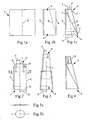
- the different embodiments illustrated in the drawings may all be formed from a planar sheet of material 1 which is folded double at a folding line 2, as seen in figs. 1a-1b .
- the meeting longitudinal edges are jointed in a seam 3, such as through gluing, providing this way a flat elongate member that is deformable into a tubular sheath extending longitudinally from a bottom or insert end 4 to a top or mouth end 5.
- similarly operating tubular sheets may be alternatively formed from planar sheets of material, such as through cutting sheath sections which are combined into a tubular member by joining the longitudinal margins of the sheath sections, or through a rolling procedure wherein a planar sheet of material is formed to a tube which is sealed at a longitudinal seam.
- a straight cylindrical sheath may be formed as in fig. 1b , illustrating a first embodiment of the plant protection device.
- a conical sheath may be formed through the single folding and joining of meeting edges.
- a conical sheath may alternatively be formed through a second folding line 6, that runs diagonally from a center position at the mouth end to a corner position at the insert end of the double-folded sheet of material.
- the second folding may likewise be secured through gluing, at least locally as indicated by reference number 7, or alternatively along the length of the longitudinal and folded-in edge 8 of the double-folded sheet of material.
- the insert end 4 may be cut as indicated in fig. 1c by a broken line c, in order to achieve a base oriented transversely to the longitudinal L.
- a third embodiment of the invention involves the folding in of one, or both, mouth end corners 9, 10 of the double-folded sheet of material, and attaching the folded-in corners to the exterior of the sheath as indicated at 11, 12.
- specifically advantageous embodiments of the invention comprise a tubular sheath having a first radius r1 at the top end 5, and at the bottom end 4 a second radius r2 wider than said first radius, wherein below a region T at the top end the sheath made of decomposable material is treated to provide a slower rate of decomposition than a rate of decomposition at said top end region.
- the rate of decomposition in the top end region T may be controlled through corresponding treatment of the material so as to preserve the integrity of the top region T primarily up to termination of the planting procedure and for a maximum of 3 years, while below this top region the material is treated so as to preserve the integrity of the sheath wall up to 2 or 3 years (depending on the risk of Pine weevil attack) and for a maximum of about 6 years, all counted from the time of planting.
- the material may be additionally treated through at least one of impregnation, coating, added material thickness and additional layers of material, in order to preserve the integrity of the bottom region for the operative time of protection in spite of the more aggressive environment resulting from ground contact.
- the plant protection device is composed of two sheaths in telescopic relation, this way allowing adjustment of the length of the tubular sheath with respect to the height of the seedling.
- the telescopic embodiment comprises an inner conical sheath coaxially adjustable within an outer conical sheath, such that a fixed axial dimension or height of the sheaths in combination is achievable by extending the sheaths telescopically until friction locks the sheaths in extended position.
- Fig. 4 illustrates yet another embodiment wherein ribs 13 project upwards from the mouth end.
- the ribs 13 may be formed through slitting or cutting an end area of the planar sheet of material before folding, e.g., or by attaching separate ribs to the sheet of material.
- the ribs 13 are operative for preventing animals from grazing on the top-bud of the seedling, projecting from the mouth end of the sheath when applied about the seedling.
- Fig. 5a illustrates a storing/transportation mode of the plant protection device, the generally flat storing condition of fig. 5 being typical for all embodiments of the sheath when produced as described.
- the tubular sheath so produced tends to collapse into a generally flat condition suitable for storing and transport with a minimum space requirement.
- the collapsed sheath is openable as illustrated in fig. 5b , providing an inner round transverse section by which the sheath is able to be threaded over a seedling from its top end towards its root end as illustrated in figs. 6a-6d .
- the plant protection device In applied position as shown in figs. 6a-6d , the plant protection device rests by its insert end 4 supported onto the upper surface of a peat clod 14 (in case of containerized seedling) containing the seedling's root system.
- the length of the tubular sheath is adapted to the height of the seedling, allowing at least the top-bud and upper lateral buds 15 of the seedling to project from the mouth end, while the lateral buds there below are covered and enclosed by the tubular sheath.
- the sheath is frictionally arrested about the seedling while engaging under a gripping force the green part comprising stem, branches and needles of the seedling as shown in fig. 6a .
- the bias provided from folding will gradually cease resulting in a corresponding cease of the gripping force in advance of disintegration of the material structuring the sheath wall, i.e. in advance of disintegration of the sheath wall in its entirety.
- the tubular sheath when applied about the seedling does not extend radially outside the peat clod, i.e. the sheath allows the protected containerized seedling to be advanced through the ordinary plantation pipes that are commonly used in the procedure of forest regeneration/planting.
- the sheath when applied also allows deep-planting of the seedling, wherein sheath and green part of the seedling are entered into the ground for approximately 40 mm, a planting procedure that is well known to further increase the survival rate of the seedlings.
- the plant protection device need not penetrate into the peat clod or encircle the root system, thus avoiding the risk of future deformation of the seedling's root system.
- the gripping force operative for axially arresting the tubular sheath about the seedling may alternatively be provided as illustrated in figs. 6b-6d . Arresting may thus be ensured by forming, as illustrated in figs. 6b and 6c , a restriction at the mouth end such as provided through the mouth periphery 16 of the conically shaped second embodiment, or through the folded in corners 9 or/and 10 of the third embodiment.
- a gripping force may alternative be provided through the arrangement of projections 17 extending inwards/upwards from an inner side of the wall defining the tubular sheath, as illustrated in fig. 6d .
- the projections 17 may be formed through slitting or cutting flaps 17 at the insert end area of the planar sheet of material and turning the flaps upwards before folding the sheet double.
- the gripping force is sufficient to keep the sheath located about the seedling and arrested vertically to the green part thereof, while avoiding any gap being formed between the sheath base and the peat clod/root system.
- Pine weevils are prevented from reaching the seedling.
- tubular sheath In applied position about the seedling, all embodiments of the tubular sheath rests by its base 18 contacting the top side of the peat clod 14 of the containerized seedling, or in case of a bare-root seedling contacting the top-side of the open root-system, while the mouth end is positioned below the top-bud and upper lateral buds 15 of the seedling as illustrated in figs. 6a-6d .
- nutrient supply to the seedling is selectively directed to the top-bud and upper lateral buds, this way effecting an accelerated vertical growth, improving the competitiveness of the seedling and supporting a radial growth reaching a stem-base diameter of 13 mm which is considered safe from Pine weevil damages.
- the plant protection device of the present invention is produced preferably from a material that is flexible in a direction transverse to the longitudinal extension of the device.
- the flexibility is advantageous and utilized in the handling of the seedling and sheath in combination.
- the sheath is applied about the seedling, the two are easily handled simply by pressing the sheath tighter about the seedling between thumb and fingers in direction of the arrows P in fig. 6a .
- each embodiment disclosed results in a sheath that provides rigidity in the longitudinal direction.
- the plant protection device of the present invention is produced from a decomposable material, preferably from a fibrous nature material such as cellulose fibers forming a sheet material that is treated with an impregnating agent or/and a coating agent, such as a polymer coating.
- a non-colored or white paper of 160 g/m 2 weight treated with stearic acid shows an endurance of 2-3 years above ground level, before being decomposed.
- a gradually enhanced resistance to decomposition and slower rate of decomposition below the top end may be provided as further explained from a number of model tests of embodiments of the invention, below referred to as Integrated Plant Protection (IPP) models.
- IPP Integrated Plant Protection
- a common and essential feature of all embodiments is that the gripping force exerted on the green part of the seedling gradually ceases in result of fatigue or in result of decomposition of the material from which the sheath is formed, and in advance of a total disintegration of the material structuring the sheath.
- the sheath effectively protects the seedling by circumferentially enclosing the green part thereof also when the gripping force has ceased, until the decomposition process results in a total disintegration of the sheath wall.
- the above examples show that the desired operation also is attainable by controlling a rate of decomposition such that decomposition is faster in that region of the sheath that initially provides the gripping force.
- the examples also show that the initial gripping force may be provided through the formation of a local restriction of the tubular section enclosing the seedling, through the inherent lateral bias of a flexible sheath wall surrounding the seedling, or through the formation of internal projections engaging the green part of the seedling.
- the gripping force provided as indicated through the embodiments disclosed will cease correspondingly due to a gradual fatigue or disintegration of the material, enhanced or alternatively provided as desired through the appropriate treatment of the material resulting in the control of the decomposition rate.
Landscapes
- Health & Medical Sciences (AREA)
- General Health & Medical Sciences (AREA)
- Toxicology (AREA)
- Life Sciences & Earth Sciences (AREA)
- Environmental Sciences (AREA)
- Protection Of Plants (AREA)
- Cultivation Receptacles Or Flower-Pots, Or Pots For Seedlings (AREA)
Claims (9)
- Dispositif de protection de plante comprenant une gaine tubulaire constituée d'une paroi de matériau décomposable et s'étendant longitudinalement d'une extrémité d'insert ouverte (4) à une extrémité de sommet ouverte (5), la paroi de gaine définissant une section tubulaire intérieure dont la taille permet à la gaine d'être appliquée au-dessus d'un semis tout en renfermant le semis depuis l'extrémité de ses racines jusqu'au-dessous de son extrémité de sommet, dans lequel la gaine tubulaire est constituée d'une feuille de matériau pliée en deux, les bords longitudinaux de celle-ci se rejoignant sont joints dans une jointure, et, en conséquence d'une polarisation inhérente de la feuille de matériau pliée en deux qui a tendance à mettre la gaine tubulaire dans un état affaissé, la gaine est arrêtée par frottement autour du semis tout en se mettant en prise, sous l'effet d'une force d'accrochage, avec la partie verte du semis comprenant une tige, des branches et des aiguilles, caractérisé en ce que la force d'accrochage est fournie à partir d'une restriction (r1) de ladite section tubulaire de la gaine et la restriction (r1) est formée à l'extrémité de sommet (5) de la gaine en repliant l'un ou les deux coins d'extrémité de sommet (9, 10) de la feuille de matériau pliée en deux et en attachant les coins repliés à l'extérieur de la gaine, de telle manière que la gaine présente un premier rayon (r1) à l'extrémité de sommet (5) et, à l'extrémité d'insert (4), un deuxième rayon (r2) plus grand que ledit premier rayon, dans lequel, au-dessous d'une région (T) à l'extrémité de sommet, la gaine est traitée pour présenter une vitesse de décomposition inférieure à une vitesse de décomposition dans ladite région d'extrémité de sommet (T).
- Dispositif de protection de plante selon la revendication 1, dans lequel la gaine se compose d'un matériau naturel fibreux qui est traité pour présenter une vitesse de décomposition progressive dans l'extension longitudinale de la gaine.
- Dispositif de protection de plante selon la revendication 2, dans lequel, à une région de fond (B), la gaine est traitée pour présenter une vitesse de décomposition inférieure à une vitesse de décomposition au-dessus de ladite région de fond (B).
- Dispositif de protection de plante selon la revendication 2 ou 3, dans lequel ledit traitement comprend au moins l'un d'une imprégnation, d'un revêtement, d'une augmentation d'épaisseur de matériau et d'une augmentation de nombre de couches de matériau.
- Dispositif de protection de plante selon la revendication 4, dans lequel la gaine se compose d'un matériau de fibres de cellulose enduit de polymère.
- Dispositif de protection de plante selon la revendication 4, dans lequel la gaine se compose de papier imprégné d'acide stéarique.
- Dispositif de protection de plante selon l'une quelconque des revendications 4 à 6, dans lequel la gaine présente une épaisseur de paroi à l'extrémité d'insert qui est supérieure à une épaisseur de paroi à l'extrémité de sommet.
- Dispositif de protection de plante selon la revendication 7, dans lequel l'épaisseur de paroi supérieure à l'extrémité d'insert est fournie par des couches supplémentaires de matériau.
- Dispositif de protection de plante selon l'une quelconque des revendications précédentes, comprenant des gaines tubulaires intérieure et extérieure en relation télescopique.
Priority Applications (1)
| Application Number | Priority Date | Filing Date | Title |
|---|---|---|---|
| PL07748477T PL2018097T3 (pl) | 2006-05-16 | 2007-05-08 | Urządzenie do ochrony roślin |
Applications Claiming Priority (2)
| Application Number | Priority Date | Filing Date | Title |
|---|---|---|---|
| SE0601083A SE529935C2 (sv) | 2006-05-16 | 2006-05-16 | Plantskyddsanordning |
| PCT/SE2007/050316 WO2007133159A1 (fr) | 2006-05-16 | 2007-05-08 | Dispositif pour la protection d'une plante |
Publications (2)
| Publication Number | Publication Date |
|---|---|
| EP2018097A1 EP2018097A1 (fr) | 2009-01-28 |
| EP2018097B1 true EP2018097B1 (fr) | 2015-11-11 |
Family
ID=38694161
Family Applications (1)
| Application Number | Title | Priority Date | Filing Date |
|---|---|---|---|
| EP07748477.2A Active EP2018097B1 (fr) | 2006-05-16 | 2007-05-08 | Dispositif pour la protection d'une plante |
Country Status (5)
| Country | Link |
|---|---|
| EP (1) | EP2018097B1 (fr) |
| DK (1) | DK2018097T3 (fr) |
| PL (1) | PL2018097T3 (fr) |
| SE (1) | SE529935C2 (fr) |
| WO (1) | WO2007133159A1 (fr) |
Families Citing this family (5)
| Publication number | Priority date | Publication date | Assignee | Title |
|---|---|---|---|---|
| GB0618988D0 (en) * | 2006-09-26 | 2006-11-08 | Tubex Ltd | Apparatus for protecting plants |
| SE533773C2 (sv) | 2009-05-12 | 2011-01-11 | Proforestry Sweden Ab | Anordning för applicering av en hylsa på en växtplanta |
| FR2949941A1 (fr) * | 2009-09-16 | 2011-03-18 | Brieg Lemetayer | Dispositif de protection de plant de vegetaux |
| WO2016054133A2 (fr) * | 2014-09-30 | 2016-04-07 | Geophysical Technology, Inc. | Manchon de contact au sol biodégradable pour un nœud d'acquisition de données sismiques |
| ES2582356B1 (es) * | 2016-03-14 | 2017-04-24 | Cartonajes Santorromán, S.A. | Protector para plantas jóvenes, procedimiento de tratado de una plantilla de cartón para fabricación de dicho protector y máquina para puesta en práctica de dicho procedimiento |
Family Cites Families (11)
| Publication number | Priority date | Publication date | Assignee | Title |
|---|---|---|---|---|
| US1704801A (en) * | 1927-01-11 | 1929-03-12 | F M Mitchell | Plant protector |
| SE386564B (sv) * | 1973-12-20 | 1976-08-16 | Bonnier Hospital Ind Ab | Skyddande huv for i marken planterade plantor eller vid sadd av fron samt verktyg for nedtryckning av huven i marken |
| GB2104366A (en) * | 1981-08-07 | 1983-03-09 | Mac Millan Bloedel Containers | Young plant protection device |
| FI921628A (fi) * | 1992-04-10 | 1993-10-11 | Agrame Ab Oy | Apparat foer plantskydd |
| GB2290691B (en) * | 1994-07-02 | 1998-03-18 | Ian Mclachlan Davis | Tree and shrub protector |
| US5692337A (en) * | 1995-06-07 | 1997-12-02 | Motz, Jr.; Ronald W. | Collapsible plant shelter |
| US20030041512A1 (en) | 2001-09-04 | 2003-03-06 | Hazeltine Leland F. | Staggered walkers forest management process |
| GB0201403D0 (en) | 2002-01-23 | 2002-03-13 | Jones Adrianne J | Improvements in and relating to tree and shrub protection |
| GB0211606D0 (en) | 2002-05-21 | 2002-07-03 | Gearing Robert | Plant shelter |
| FR2850242B1 (fr) * | 2003-01-29 | 2005-09-30 | Guy Andre Aribaud | Protection de jeunes plants biodegradable |
| AU2004289067A1 (en) * | 2003-11-14 | 2005-05-26 | Ahlstrom Corporation | Plant protection device |
-
2006
- 2006-05-16 SE SE0601083A patent/SE529935C2/sv not_active IP Right Cessation
-
2007
- 2007-05-08 PL PL07748477T patent/PL2018097T3/pl unknown
- 2007-05-08 WO PCT/SE2007/050316 patent/WO2007133159A1/fr active Application Filing
- 2007-05-08 DK DK07748477.2T patent/DK2018097T3/en active
- 2007-05-08 EP EP07748477.2A patent/EP2018097B1/fr active Active
Also Published As
| Publication number | Publication date |
|---|---|
| SE529935C2 (sv) | 2008-01-08 |
| WO2007133159A1 (fr) | 2007-11-22 |
| SE0601083L (sv) | 2007-11-17 |
| DK2018097T3 (en) | 2016-02-22 |
| EP2018097A1 (fr) | 2009-01-28 |
| PL2018097T3 (pl) | 2016-06-30 |
Similar Documents
| Publication | Publication Date | Title |
|---|---|---|
| EP2018097B1 (fr) | Dispositif pour la protection d'une plante | |
| DE102009003164B4 (de) | Pflanzhülse | |
| US6108970A (en) | Self-watering plant guard | |
| CN107426973A (zh) | 板状结构、储器和方法 | |
| US5090155A (en) | Seedling protector | |
| WO2013019105A2 (fr) | Plateau de plantes permettant la croissance de plantes, plateau, pot et procédés | |
| EP2638801B1 (fr) | Dispositif pour le contrôle d'insectes du sol | |
| KR20160003350U (ko) | 묘종 매트 | |
| US20130036666A1 (en) | Bio-degradable Fertilizer Pad | |
| WO1996028010A1 (fr) | Milieu contenant des graines | |
| US20050086862A1 (en) | Plant root and bulb protection device | |
| EP1681916B1 (fr) | Dispositif de protection de plantes | |
| JP2008283911A (ja) | 害獣忌避具及び害獣侵入防止柵と害獣忌避工法 | |
| DE102007015760A1 (de) | Vorrichtung zum Verhindern eines Unkrautwachstums, Verfahren zum Herstellen einer Unkrautwachstumssperre und Verwendung eines Vliesmaterials für eine Unkrautwachstumssperre | |
| JPH09294481A (ja) | 育苗移植用紙鉢 | |
| AU716241B2 (en) | Self-watering plant guard | |
| AU2007100624A4 (en) | Plant container | |
| NL2007198C2 (en) | A plant tray for propagating plants, a tray, and methods. | |
| NL2008179C2 (en) | A plant tray for propagating plants, a tray, and methods. | |
| CA1319257C (fr) | Revetement de cuves | |
| NO20200135A1 (en) | Device for deploying seeds into the soil of a cultivation field | |
| JP2019180336A (ja) | ツリーシェルター及び樹木の製造方法 | |
| FI78218B (fi) | Skyddshoelje foer skydd av skogsplantor mot insektsangrepp. | |
| WO2019224317A1 (fr) | Structure d'enracinement | |
| US20070051034A1 (en) | Plant protection device |
Legal Events
| Date | Code | Title | Description |
|---|---|---|---|
| PUAI | Public reference made under article 153(3) epc to a published international application that has entered the european phase |
Free format text: ORIGINAL CODE: 0009012 |
|
| 17P | Request for examination filed |
Effective date: 20081106 |
|
| AK | Designated contracting states |
Kind code of ref document: A1 Designated state(s): AT BE BG CH CY CZ DE DK EE ES FI FR GB GR HU IE IS IT LI LT LU LV MC MT NL PL PT RO SE SI SK TR |
|
| AX | Request for extension of the european patent |
Extension state: AL BA HR MK RS |
|
| RAP1 | Party data changed (applicant data changed or rights of an application transferred) |
Owner name: PROFORESTRY SWEDEN AB |
|
| RAP1 | Party data changed (applicant data changed or rights of an application transferred) |
Owner name: MPH SKYDD AB |
|
| 17Q | First examination report despatched |
Effective date: 20120430 |
|
| DAX | Request for extension of the european patent (deleted) | ||
| REG | Reference to a national code |
Ref country code: DE Ref legal event code: R079 Ref document number: 602007043860 Country of ref document: DE Free format text: PREVIOUS MAIN CLASS: A01G0013020000 Ipc: A01G0013000000 |
|
| RIC1 | Information provided on ipc code assigned before grant |
Ipc: A01G 13/00 20060101AFI20150416BHEP |
|
| GRAP | Despatch of communication of intention to grant a patent |
Free format text: ORIGINAL CODE: EPIDOSNIGR1 |
|
| INTG | Intention to grant announced |
Effective date: 20150604 |
|
| GRAS | Grant fee paid |
Free format text: ORIGINAL CODE: EPIDOSNIGR3 |
|
| GRAA | (expected) grant |
Free format text: ORIGINAL CODE: 0009210 |
|
| AK | Designated contracting states |
Kind code of ref document: B1 Designated state(s): AT BE BG CH CY CZ DE DK EE ES FI FR GB GR HU IE IS IT LI LT LU LV MC MT NL PL PT RO SE SI SK TR |
|
| REG | Reference to a national code |
Ref country code: GB Ref legal event code: FG4D |
|
| REG | Reference to a national code |
Ref country code: CH Ref legal event code: EP |
|
| REG | Reference to a national code |
Ref country code: IE Ref legal event code: FG4D |
|
| REG | Reference to a national code |
Ref country code: AT Ref legal event code: REF Ref document number: 759951 Country of ref document: AT Kind code of ref document: T Effective date: 20151215 |
|
| REG | Reference to a national code |
Ref country code: DE Ref legal event code: R096 Ref document number: 602007043860 Country of ref document: DE |
|
| REG | Reference to a national code |
Ref country code: DK Ref legal event code: T3 Effective date: 20160215 |
|
| REG | Reference to a national code |
Ref country code: SE Ref legal event code: TRGR |
|
| REG | Reference to a national code |
Ref country code: LT Ref legal event code: MG4D |
|
| REG | Reference to a national code |
Ref country code: NL Ref legal event code: MP Effective date: 20160211 |
|
| PG25 | Lapsed in a contracting state [announced via postgrant information from national office to epo] |
Ref country code: NL Free format text: LAPSE BECAUSE OF FAILURE TO SUBMIT A TRANSLATION OF THE DESCRIPTION OR TO PAY THE FEE WITHIN THE PRESCRIBED TIME-LIMIT Effective date: 20151111 Ref country code: ES Free format text: LAPSE BECAUSE OF FAILURE TO SUBMIT A TRANSLATION OF THE DESCRIPTION OR TO PAY THE FEE WITHIN THE PRESCRIBED TIME-LIMIT Effective date: 20151111 Ref country code: IS Free format text: LAPSE BECAUSE OF FAILURE TO SUBMIT A TRANSLATION OF THE DESCRIPTION OR TO PAY THE FEE WITHIN THE PRESCRIBED TIME-LIMIT Effective date: 20160311 Ref country code: LT Free format text: LAPSE BECAUSE OF FAILURE TO SUBMIT A TRANSLATION OF THE DESCRIPTION OR TO PAY THE FEE WITHIN THE PRESCRIBED TIME-LIMIT Effective date: 20151111 Ref country code: IT Free format text: LAPSE BECAUSE OF FAILURE TO SUBMIT A TRANSLATION OF THE DESCRIPTION OR TO PAY THE FEE WITHIN THE PRESCRIBED TIME-LIMIT Effective date: 20151111 |
|
| REG | Reference to a national code |
Ref country code: FR Ref legal event code: PLFP Year of fee payment: 10 |
|
| PG25 | Lapsed in a contracting state [announced via postgrant information from national office to epo] |
Ref country code: PT Free format text: LAPSE BECAUSE OF FAILURE TO SUBMIT A TRANSLATION OF THE DESCRIPTION OR TO PAY THE FEE WITHIN THE PRESCRIBED TIME-LIMIT Effective date: 20160311 Ref country code: GR Free format text: LAPSE BECAUSE OF FAILURE TO SUBMIT A TRANSLATION OF THE DESCRIPTION OR TO PAY THE FEE WITHIN THE PRESCRIBED TIME-LIMIT Effective date: 20160212 Ref country code: LV Free format text: LAPSE BECAUSE OF FAILURE TO SUBMIT A TRANSLATION OF THE DESCRIPTION OR TO PAY THE FEE WITHIN THE PRESCRIBED TIME-LIMIT Effective date: 20151111 |
|
| PG25 | Lapsed in a contracting state [announced via postgrant information from national office to epo] |
Ref country code: CZ Free format text: LAPSE BECAUSE OF FAILURE TO SUBMIT A TRANSLATION OF THE DESCRIPTION OR TO PAY THE FEE WITHIN THE PRESCRIBED TIME-LIMIT Effective date: 20151111 |
|
| REG | Reference to a national code |
Ref country code: DE Ref legal event code: R097 Ref document number: 602007043860 Country of ref document: DE |
|
| PG25 | Lapsed in a contracting state [announced via postgrant information from national office to epo] |
Ref country code: BE Free format text: LAPSE BECAUSE OF NON-PAYMENT OF DUE FEES Effective date: 20160531 Ref country code: SK Free format text: LAPSE BECAUSE OF FAILURE TO SUBMIT A TRANSLATION OF THE DESCRIPTION OR TO PAY THE FEE WITHIN THE PRESCRIBED TIME-LIMIT Effective date: 20151111 Ref country code: RO Free format text: LAPSE BECAUSE OF FAILURE TO SUBMIT A TRANSLATION OF THE DESCRIPTION OR TO PAY THE FEE WITHIN THE PRESCRIBED TIME-LIMIT Effective date: 20151111 Ref country code: EE Free format text: LAPSE BECAUSE OF FAILURE TO SUBMIT A TRANSLATION OF THE DESCRIPTION OR TO PAY THE FEE WITHIN THE PRESCRIBED TIME-LIMIT Effective date: 20151111 |
|
| PLBE | No opposition filed within time limit |
Free format text: ORIGINAL CODE: 0009261 |
|
| STAA | Information on the status of an ep patent application or granted ep patent |
Free format text: STATUS: NO OPPOSITION FILED WITHIN TIME LIMIT |
|
| 26N | No opposition filed |
Effective date: 20160812 |
|
| PG25 | Lapsed in a contracting state [announced via postgrant information from national office to epo] |
Ref country code: SI Free format text: LAPSE BECAUSE OF FAILURE TO SUBMIT A TRANSLATION OF THE DESCRIPTION OR TO PAY THE FEE WITHIN THE PRESCRIBED TIME-LIMIT Effective date: 20151111 |
|
| PG25 | Lapsed in a contracting state [announced via postgrant information from national office to epo] |
Ref country code: LU Free format text: LAPSE BECAUSE OF FAILURE TO SUBMIT A TRANSLATION OF THE DESCRIPTION OR TO PAY THE FEE WITHIN THE PRESCRIBED TIME-LIMIT Effective date: 20160508 Ref country code: BE Free format text: LAPSE BECAUSE OF FAILURE TO SUBMIT A TRANSLATION OF THE DESCRIPTION OR TO PAY THE FEE WITHIN THE PRESCRIBED TIME-LIMIT Effective date: 20151111 |
|
| REG | Reference to a national code |
Ref country code: CH Ref legal event code: PL |
|
| PG25 | Lapsed in a contracting state [announced via postgrant information from national office to epo] |
Ref country code: CH Free format text: LAPSE BECAUSE OF NON-PAYMENT OF DUE FEES Effective date: 20160531 Ref country code: LI Free format text: LAPSE BECAUSE OF NON-PAYMENT OF DUE FEES Effective date: 20160531 |
|
| REG | Reference to a national code |
Ref country code: FR Ref legal event code: PLFP Year of fee payment: 11 |
|
| REG | Reference to a national code |
Ref country code: FR Ref legal event code: PLFP Year of fee payment: 12 |
|
| PG25 | Lapsed in a contracting state [announced via postgrant information from national office to epo] |
Ref country code: CY Free format text: LAPSE BECAUSE OF FAILURE TO SUBMIT A TRANSLATION OF THE DESCRIPTION OR TO PAY THE FEE WITHIN THE PRESCRIBED TIME-LIMIT Effective date: 20151111 Ref country code: HU Free format text: LAPSE BECAUSE OF FAILURE TO SUBMIT A TRANSLATION OF THE DESCRIPTION OR TO PAY THE FEE WITHIN THE PRESCRIBED TIME-LIMIT; INVALID AB INITIO Effective date: 20070508 |
|
| PG25 | Lapsed in a contracting state [announced via postgrant information from national office to epo] |
Ref country code: MT Free format text: LAPSE BECAUSE OF NON-PAYMENT OF DUE FEES Effective date: 20160531 Ref country code: MC Free format text: LAPSE BECAUSE OF FAILURE TO SUBMIT A TRANSLATION OF THE DESCRIPTION OR TO PAY THE FEE WITHIN THE PRESCRIBED TIME-LIMIT Effective date: 20151111 Ref country code: TR Free format text: LAPSE BECAUSE OF FAILURE TO SUBMIT A TRANSLATION OF THE DESCRIPTION OR TO PAY THE FEE WITHIN THE PRESCRIBED TIME-LIMIT Effective date: 20151111 |
|
| PG25 | Lapsed in a contracting state [announced via postgrant information from national office to epo] |
Ref country code: BG Free format text: LAPSE BECAUSE OF FAILURE TO SUBMIT A TRANSLATION OF THE DESCRIPTION OR TO PAY THE FEE WITHIN THE PRESCRIBED TIME-LIMIT Effective date: 20151111 |
|
| REG | Reference to a national code |
Ref country code: AT Ref legal event code: UEP Ref document number: 759951 Country of ref document: AT Kind code of ref document: T Effective date: 20151111 |
|
| PGFP | Annual fee paid to national office [announced via postgrant information from national office to epo] |
Ref country code: SE Payment date: 20220517 Year of fee payment: 16 Ref country code: GB Payment date: 20220518 Year of fee payment: 16 Ref country code: FR Payment date: 20220516 Year of fee payment: 16 Ref country code: DK Payment date: 20220517 Year of fee payment: 16 Ref country code: DE Payment date: 20220519 Year of fee payment: 16 |
|
| PGFP | Annual fee paid to national office [announced via postgrant information from national office to epo] |
Ref country code: FI Payment date: 20220513 Year of fee payment: 16 Ref country code: AT Payment date: 20220519 Year of fee payment: 16 |
|
| PGFP | Annual fee paid to national office [announced via postgrant information from national office to epo] |
Ref country code: IE Payment date: 20230508 Year of fee payment: 17 |
|
| PGFP | Annual fee paid to national office [announced via postgrant information from national office to epo] |
Ref country code: PL Payment date: 20230411 Year of fee payment: 17 |
|
| REG | Reference to a national code |
Ref country code: DE Ref legal event code: R119 Ref document number: 602007043860 Country of ref document: DE |
|
| REG | Reference to a national code |
Ref country code: SE Ref legal event code: EUG Ref country code: DK Ref legal event code: EBP Effective date: 20230531 |
|
| REG | Reference to a national code |
Ref country code: AT Ref legal event code: MM01 Ref document number: 759951 Country of ref document: AT Kind code of ref document: T Effective date: 20230508 |
|
| GBPC | Gb: european patent ceased through non-payment of renewal fee |
Effective date: 20230508 |
|
| PG25 | Lapsed in a contracting state [announced via postgrant information from national office to epo] |
Ref country code: SE Free format text: LAPSE BECAUSE OF NON-PAYMENT OF DUE FEES Effective date: 20230509 Ref country code: FI Free format text: LAPSE BECAUSE OF NON-PAYMENT OF DUE FEES Effective date: 20230508 Ref country code: AT Free format text: LAPSE BECAUSE OF NON-PAYMENT OF DUE FEES Effective date: 20230508 |
|
| PG25 | Lapsed in a contracting state [announced via postgrant information from national office to epo] |
Ref country code: DK Free format text: LAPSE BECAUSE OF NON-PAYMENT OF DUE FEES Effective date: 20230531 Ref country code: DE Free format text: LAPSE BECAUSE OF NON-PAYMENT OF DUE FEES Effective date: 20231201 Ref country code: GB Free format text: LAPSE BECAUSE OF NON-PAYMENT OF DUE FEES Effective date: 20230508 |