EP2018069B1 - Vorrichtung, verfahren und programm zur schätzung von videoqualität - Google Patents
Vorrichtung, verfahren und programm zur schätzung von videoqualität Download PDFInfo
- Publication number
- EP2018069B1 EP2018069B1 EP06833537.1A EP06833537A EP2018069B1 EP 2018069 B1 EP2018069 B1 EP 2018069B1 EP 06833537 A EP06833537 A EP 06833537A EP 2018069 B1 EP2018069 B1 EP 2018069B1
- Authority
- EP
- European Patent Office
- Prior art keywords
- video quality
- degradation
- frame rate
- estimation
- coding bit
- Prior art date
- Legal status (The legal status is an assumption and is not a legal conclusion. Google has not performed a legal analysis and makes no representation as to the accuracy of the status listed.)
- Active
Links
- 238000000034 method Methods 0.000 title claims description 66
- 230000015556 catabolic process Effects 0.000 claims description 386
- 238000006731 degradation reaction Methods 0.000 claims description 386
- 238000004891 communication Methods 0.000 claims description 122
- 238000000605 extraction Methods 0.000 claims description 61
- 238000004364 calculation method Methods 0.000 claims description 58
- 239000000284 extract Substances 0.000 claims description 29
- 238000012937 correction Methods 0.000 claims description 17
- 230000006870 function Effects 0.000 description 94
- 230000008859 change Effects 0.000 description 89
- 238000009795 derivation Methods 0.000 description 55
- 238000011156 evaluation Methods 0.000 description 34
- 230000008569 process Effects 0.000 description 30
- 230000007423 decrease Effects 0.000 description 25
- 238000010586 diagram Methods 0.000 description 20
- 238000013461 design Methods 0.000 description 17
- 230000014509 gene expression Effects 0.000 description 13
- 238000012886 linear function Methods 0.000 description 10
- 230000002123 temporal effect Effects 0.000 description 9
- 230000000694 effects Effects 0.000 description 7
- 238000012546 transfer Methods 0.000 description 5
- 238000013441 quality evaluation Methods 0.000 description 3
- 230000006866 deterioration Effects 0.000 description 2
- 230000010365 information processing Effects 0.000 description 2
- 230000000007 visual effect Effects 0.000 description 2
- 238000013528 artificial neural network Methods 0.000 description 1
- 238000007796 conventional method Methods 0.000 description 1
- 230000006872 improvement Effects 0.000 description 1
- 230000003993 interaction Effects 0.000 description 1
- 238000005259 measurement Methods 0.000 description 1
- 230000003340 mental effect Effects 0.000 description 1
- 230000002093 peripheral effect Effects 0.000 description 1
- 238000012887 quadratic function Methods 0.000 description 1
- 229920006395 saturated elastomer Polymers 0.000 description 1
Images


Classifications
-
- H—ELECTRICITY
- H04—ELECTRIC COMMUNICATION TECHNIQUE
- H04N—PICTORIAL COMMUNICATION, e.g. TELEVISION
- H04N19/00—Methods or arrangements for coding, decoding, compressing or decompressing digital video signals
- H04N19/50—Methods or arrangements for coding, decoding, compressing or decompressing digital video signals using predictive coding
- H04N19/587—Methods or arrangements for coding, decoding, compressing or decompressing digital video signals using predictive coding involving temporal sub-sampling or interpolation, e.g. decimation or subsequent interpolation of pictures in a video sequence
-
- H—ELECTRICITY
- H04—ELECTRIC COMMUNICATION TECHNIQUE
- H04N—PICTORIAL COMMUNICATION, e.g. TELEVISION
- H04N17/00—Diagnosis, testing or measuring for television systems or their details
-
- H—ELECTRICITY
- H04—ELECTRIC COMMUNICATION TECHNIQUE
- H04N—PICTORIAL COMMUNICATION, e.g. TELEVISION
- H04N17/00—Diagnosis, testing or measuring for television systems or their details
- H04N17/004—Diagnosis, testing or measuring for television systems or their details for digital television systems
-
- H—ELECTRICITY
- H04—ELECTRIC COMMUNICATION TECHNIQUE
- H04N—PICTORIAL COMMUNICATION, e.g. TELEVISION
- H04N19/00—Methods or arrangements for coding, decoding, compressing or decompressing digital video signals
- H04N19/10—Methods or arrangements for coding, decoding, compressing or decompressing digital video signals using adaptive coding
- H04N19/102—Methods or arrangements for coding, decoding, compressing or decompressing digital video signals using adaptive coding characterised by the element, parameter or selection affected or controlled by the adaptive coding
- H04N19/132—Sampling, masking or truncation of coding units, e.g. adaptive resampling, frame skipping, frame interpolation or high-frequency transform coefficient masking
-
- H—ELECTRICITY
- H04—ELECTRIC COMMUNICATION TECHNIQUE
- H04N—PICTORIAL COMMUNICATION, e.g. TELEVISION
- H04N19/00—Methods or arrangements for coding, decoding, compressing or decompressing digital video signals
- H04N19/10—Methods or arrangements for coding, decoding, compressing or decompressing digital video signals using adaptive coding
- H04N19/134—Methods or arrangements for coding, decoding, compressing or decompressing digital video signals using adaptive coding characterised by the element, parameter or criterion affecting or controlling the adaptive coding
- H04N19/146—Data rate or code amount at the encoder output
-
- H—ELECTRICITY
- H04—ELECTRIC COMMUNICATION TECHNIQUE
- H04N—PICTORIAL COMMUNICATION, e.g. TELEVISION
- H04N19/00—Methods or arrangements for coding, decoding, compressing or decompressing digital video signals
- H04N19/10—Methods or arrangements for coding, decoding, compressing or decompressing digital video signals using adaptive coding
- H04N19/134—Methods or arrangements for coding, decoding, compressing or decompressing digital video signals using adaptive coding characterised by the element, parameter or criterion affecting or controlling the adaptive coding
- H04N19/154—Measured or subjectively estimated visual quality after decoding, e.g. measurement of distortion
-
- H—ELECTRICITY
- H04—ELECTRIC COMMUNICATION TECHNIQUE
- H04N—PICTORIAL COMMUNICATION, e.g. TELEVISION
- H04N19/00—Methods or arrangements for coding, decoding, compressing or decompressing digital video signals
- H04N19/10—Methods or arrangements for coding, decoding, compressing or decompressing digital video signals using adaptive coding
- H04N19/134—Methods or arrangements for coding, decoding, compressing or decompressing digital video signals using adaptive coding characterised by the element, parameter or criterion affecting or controlling the adaptive coding
- H04N19/156—Availability of hardware or computational resources, e.g. encoding based on power-saving criteria
-
- H—ELECTRICITY
- H04—ELECTRIC COMMUNICATION TECHNIQUE
- H04N—PICTORIAL COMMUNICATION, e.g. TELEVISION
- H04N19/00—Methods or arrangements for coding, decoding, compressing or decompressing digital video signals
- H04N19/10—Methods or arrangements for coding, decoding, compressing or decompressing digital video signals using adaptive coding
- H04N19/134—Methods or arrangements for coding, decoding, compressing or decompressing digital video signals using adaptive coding characterised by the element, parameter or criterion affecting or controlling the adaptive coding
- H04N19/164—Feedback from the receiver or from the transmission channel
- H04N19/166—Feedback from the receiver or from the transmission channel concerning the amount of transmission errors, e.g. bit error rate [BER]
-
- H—ELECTRICITY
- H04—ELECTRIC COMMUNICATION TECHNIQUE
- H04N—PICTORIAL COMMUNICATION, e.g. TELEVISION
- H04N19/00—Methods or arrangements for coding, decoding, compressing or decompressing digital video signals
- H04N19/60—Methods or arrangements for coding, decoding, compressing or decompressing digital video signals using transform coding
- H04N19/61—Methods or arrangements for coding, decoding, compressing or decompressing digital video signals using transform coding in combination with predictive coding
-
- H—ELECTRICITY
- H04—ELECTRIC COMMUNICATION TECHNIQUE
- H04N—PICTORIAL COMMUNICATION, e.g. TELEVISION
- H04N19/00—Methods or arrangements for coding, decoding, compressing or decompressing digital video signals
- H04N19/85—Methods or arrangements for coding, decoding, compressing or decompressing digital video signals using pre-processing or post-processing specially adapted for video compression
- H04N19/89—Methods or arrangements for coding, decoding, compressing or decompressing digital video signals using pre-processing or post-processing specially adapted for video compression involving methods or arrangements for detection of transmission errors at the decoder
-
- H—ELECTRICITY
- H04—ELECTRIC COMMUNICATION TECHNIQUE
- H04L—TRANSMISSION OF DIGITAL INFORMATION, e.g. TELEGRAPHIC COMMUNICATION
- H04L43/00—Arrangements for monitoring or testing data switching networks
- H04L43/04—Processing captured monitoring data, e.g. for logfile generation
- H04L43/045—Processing captured monitoring data, e.g. for logfile generation for graphical visualisation of monitoring data
-
- H—ELECTRICITY
- H04—ELECTRIC COMMUNICATION TECHNIQUE
- H04L—TRANSMISSION OF DIGITAL INFORMATION, e.g. TELEGRAPHIC COMMUNICATION
- H04L43/00—Arrangements for monitoring or testing data switching networks
- H04L43/08—Monitoring or testing based on specific metrics, e.g. QoS, energy consumption or environmental parameters
- H04L43/0823—Errors, e.g. transmission errors
- H04L43/0829—Packet loss
- H04L43/0835—One way packet loss
Definitions
- the present invention relates to an audiovisual communication technique and, more particularly, to a video quality estimation technique of estimating subjective video quality a viewer actually senses when a terminal receives and reproduces an audiovisual medium encoded into a plurality of frames.
- Advance in high-speed and broadband Internet access networks is raising expectations for spread of audiovisual communication services which transfer audiovisual media containing video and audio data between terminals or server terminals via the Internet.
- Audiovisual communication services of this type use encoding communication to improve the audiovisual medium transfer efficiency, in which an audiovisual medium is encoded into a plurality of frames and transferred using intra-image or inter-frame autocorrelation of the audiovisual medium or human visual characteristic.
- a best-effort network such as the Internet used for the audiovisual communication services does not always guarantee the communication quality.
- narrow bands or congestions in communication lines are perceptible as degradation in quality, i.e., subjective video quality a viewer actually senses from the audiovisual medium received and reproduced via the communication lines.
- encoding by an application adds encoding distortions to the video image, which are perceptible as degradation in subjective video quality. More specifically, the viewer perceives degradation in quality of an audiovisual medium as defocus, blur, mosaic-shaped distortion, and jerky effect in the video image.
- ITU-T recommendation P.862 International Telecommunication Union-Telecommunication Standardization Sector
- PESQ Perceptual Evaluation of Speech Quality
- ITU-T recommendation G.107 describes an audio quality estimation method which inputs audio quality parameters and is used for quality design in VoIP (Voice over IP).
- an objective video image evaluation method (e.g., ITU-T recommendation J.144: to be referred to as reference 1 hereinafter) which inputs a video signal is proposed as a recommendation.
- a video quality estimation method which inputs video quality parameters is also proposed (e.g., Yamagishi & Hayashi, "Video Quality Estimation Model based on Displaysize and Resolution for Audiovisual Communication Services", IEICE Technical Report CQ2005-90, 2005/09, pp. 61-64 : to be referred to as reference 2 hereinafter).
- This technique formalizes the video quality on the basis of the relationship between the video quality and each video quality parameter and formalizes the video quality by the linear sum of the products.
- a quality estimation model taking coding parameters and packet loss into account is also proposed (e.g., Arayama, Kitawaki, & Yamada, "Opinion model for audio-visual communication quality for quality parameters by coding and packet loss", IEICE Technical Report CQ2005-77, 2005/11, pp. 57-60 : to be referred to as reference 3 hereinafter).
- JP 2006-074333 A relates to accurately estimating comprehensive quality in two-way communication service using a voice and a video medium.
- factors responsible for a deterioration in quality in the two-way communication service between terminals the following are monitored: a video bit rate Br; a frame rate Fr; a video invalid packet rate Pv; a voice invalid packet rate Pa; and a delay time D.
- a factor score S 1 for an aesthetic feeling and a factor score S2 for an uplifting feeling as mental factors with respect to quality received by a user.
- the coding bit rate is a value representing the number of coding bits per unit time of an audiovisual medium.
- the frame rate is a value representing the number of frames per unit time of an audiovisual medium.
- the temporal video quality can be improved because a smooth video image is obtained.
- spatial image degradation may become noticeable because of the decrease in the number of coding bits per unit frame, resulting in poor video quality.
- spatial image degradation improves so that a higher video quality can be obtained.
- temporal frame drop with a jerky effect may take place, resulting in poor video quality.
- the packet loss rate represents a packet loss occurrence probability used to transfer an audiovisual medium, which occurs in a communication network or terminal.
- a high packet loss rate inhibits normal decoding of an encoded audiovisual medium, resulting in poor video quality. If the coding bit rate is low, the influence of the packet loss rate on the video quality is small. However, even when the packet loss rate does not change, it greatly affects the video quality if the coding bit rate is high.
- the packet loss rate has the same characteristic feature as described above even in association with the frame rate.
- the objective quality evaluation method using a video signal as an input which is described in reference 1 above, estimates the video quality in consideration of a feature of a video image, i.e., a feature calculated from spatial and temporal distortions.
- a feature of a video image i.e., a feature calculated from spatial and temporal distortions.
- References 2 and 3 above describe video quality estimation methods using video quality parameters as an input. These methods, however, do not consider the fact that the influence of packet loss on video quality changes depending on the set of the coding bit rate and frame rate. It is therefore impossible to obtain specific and useful guidelines for quality design/management in quality design and quality management of applications and networks.
- the present invention has been made to solve the above-described problems, and has as its object to provide a video quality estimation apparatus, method, and program capable of obtaining specific and useful guidelines for quality design/management considering the influence of the packet loss rate on video quality, which changes depending on the coding bit rate and frame rate.
- An exemplary video quality estimation apparatus may comprise a parameter extraction unit which extracts, as main parameters, an input coding bit rate representing the number of coding bits per unit time, an input frame rate representing the number of frames per unit time, and an input packet loss rate representing a packet loss occurrence probability of an audiovisual medium encoded into a plurality of frames, a first storage unit which stores reference subjective video quality representing subjective video quality of the audiovisual medium encoded at the input coding bit rate and the input frame rate without packet loss, a degradation model specifying unit which specifies a degradation model representing a relationship between the input packet loss rate and degradation in the reference subjective video quality on the basis of the input coding bit rate and the input frame rate, and a video quality correction unit which corrects the reference subjective video quality on the basis of a video quality degradation ratio corresponding to the input packet loss rate, which is calculated by using the specified degradation model, thereby calculating an estimation value of subjective video quality a viewer actually senses from the audiovisual medium received via a communication network and reproduced on an arbitrary terminal.
- An exemplary video quality estimation method may comprise the steps of causing a parameter extraction unit to extract, as main parameters, an input coding bit rate representing the number of coding bits per unit time, an input frame rate representing the number of frames per unit time, and an input packet loss rate representing a packet loss occurrence probability of an audiovisual medium encoded into a plurality of frames, causing a first storage unit to store reference subjective video quality representing subjective video quality of the audiovisual medium encoded at the input coding bit rate and the input frame rate without packet loss, causing a degradation model specifying unit to specify a degradation model representing a relationship between the input packet loss rate and degradation in the reference subjective video quality on the basis of the input coding bit rate and the input frame rate, and causing a video quality correction unit to correct the reference subjective video quality on the basis of a video quality degradation ratio corresponding to the input packet loss rate, which is calculated by using the specified degradation model, thereby calculating an estimation value of subjective video quality a viewer actually senses from the audiovisual medium received via a communication network and reproduced on an arbitrary
- An exemplary program may cause a computer of a video quality estimation apparatus which calculates, for audiovisual communication to transmit an audiovisual medium encoded into a plurality of frames to an arbitrary terminal via a communication network, an estimation value of subjective video quality a viewer actually senses from the audiovisual medium reproduced on the terminal, to execute the steps of causing a parameter extraction unit to extract, as main parameters, an input coding bit rate representing the number of coding bits per unit time, an input frame rate representing the number of frames per unit time, and an input packet loss rate representing a packet loss occurrence probability of an audiovisual medium encoded into a plurality of frames, causing a storage unit to store reference subjective video quality representing subjective video quality of the audiovisual medium encoded at the input coding bit rate and the input frame rate without packet loss, causing a degradation model specifying unit to specify a degradation model representing a relationship between the input packet loss rate and degradation in the reference subjective video quality on the basis of the input coding bit rate and the input frame rate, and causing a video quality correction unit to correct the reference subjective
- the degradation model specifying unit specifies a degradation model representing the relationship between the packet loss rate and the degradation in reference subjective video quality on the basis of the input frame rate and input coding bit rate.
- the reference subjective video quality is corrected on the basis of a video quality degradation ratio corresponding to the input packet loss rate calculated by using the degradation model.
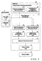
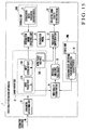
- FIG. 1 is a block diagram showing the arrangement of the video quality estimation apparatus according to the first embodiment of the present invention.
- a video quality estimation apparatus 1 is formed from an information processing apparatus such as a computer that calculates input information.
- the video quality estimation apparatus 1 inputs estimation conditions about the audiovisual medium and the communication network and calculates, by using a predetermined estimation model, the estimation value of subjective video quality a viewer actually senses from the audiovisual medium reproduced on the terminal.
- an input coding bit rate representing the number of coding bits per unit time, an input frame rate representing the number of frames per unit time, and an input packet loss rate representing the packet loss occurrence probability of an audiovisual medium are input.
- a degradation model representing the relationship between the packet loss rate and degradation in reference subjective video quality is specified on the basis of the input coding bit rate and input frame rate.
- the reference subjective video quality is corrected on the basis of a video quality degradation ratio corresponding to a packet loss calculated by the specified degradation model, thereby calculating an estimation value.
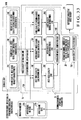
- Fig. 2 is a block diagram showing the arrangement of the degradation model specifying unit of the video quality estimation apparatus according to the first embodiment of the present invention.
- the video quality estimation apparatus 1 includes a parameter extraction unit 11, degradation model specifying unit 12, and video quality estimation unit 13 as main functional units. These functional units may be implemented either by dedicated calculation circuits or by providing a microprocessor such as a CPU and its peripheral circuits and making the microprocessor read out and execute a program prepared in advance to cause the hardware and program to cooperate with each other. Storage units (to be described later) including storage devices such as a memory and a hard disk store pieces of process information used in these functional units. The pieces of process information are exchanged between the functional units via a storage unit (not shown) including a storage device. The program may be stored in the storage unit.
- the video quality estimation apparatus 1 also includes various fundamental components such as a storage device, operation input device, and screen display device, like a general information processing apparatus.
- the parameter extraction unit 11 has a function of extracting various kinds of estimation conditions 10 related to an evaluation target audiovisual communication service, a function of extracting a frame rate and a coding bit rate related to encoding of an audiovisual medium from the estimation conditions 10, a function of extracting, from the estimation conditions 10, a packet loss rate related to the performance of a terminal and a communication network to transfer an audiovisual medium, and a function of outputting the extracted coding bit rate, frame rate, and packet loss rate as main parameters 21 including an input frame rate fr (21A), an input coding bit rate br (21B), and input packet loss rate pl (21C).
- the operator can input the estimation conditions 10 by using an operation input device such as a keyboard.
- the estimation conditions 10 may be either acquired from an external device, recording medium, or communication network by using a data input/output device for inputting/outputting data or measured from an actual audiovisual communication service.
- the input packet loss rate pl (21C) can include one or both of a packet loss in the communication network and a packet loss in the terminal depending on the characteristic feature of the audiovisual communication service or desired subjective video quality.
- the degradation model specifying unit 12 has a function of specifying a degradation model 22 representing the relationship between the packet loss rate and degradation in the reference subjective video quality 23 on the basis of the input frame rate 21A and input coding bit rate 21B of the main parameters 21 output from the parameter extraction unit 11.
- the reference subjective video quality 23 is subjective video quality of an audiovisual medium encoded at the input any frame rate 21A and input coding bit rate 21B without packet loss.
- the reference subjective video quality 23 may be stored in a storage unit 23M (first storage unit) in advance.
- the parameter extraction unit 11 may extract the reference subjective video quality 23 from the estimation conditions 10 together with the main parameters 21 and saves them in the storage unit 23M.
- the video quality correction unit 13 has a function of calculating a video quality degradation ratio corresponding to the input packet loss rate 21C of the main parameters 21 by referring to the degradation model 22 specified by the degradation model specifying unit 12, and a function of calculating a desired subjective video quality estimation value 24 by correcting the reference subjective video quality 23 on the basis of the video quality degradation ratio.
- the degradation model specifying unit 12 also includes several functional units, as shown in Fig. 2 .
- the main functional units include a frame rate degradation index calculation unit 12A, coding bit rate degradation index calculation unit 12B, and degradation index calculation unit 12C.
- the frame rate degradation index calculation unit 12A has a function of calculating a frame rate degradation index ⁇ 1 (fr) (first degradation index: 32A) representing the degree of influence of the packet loss rate on degradation in subjective video quality characteristic of the audiovisual medium transmitted at the input frame rate fr (21A) by referring to a frame rate vs. degradation index characteristic 31A in a storage unit 31M (second storage unit).
- the coding bit rate degradation index calculation unit 12B has a function of calculating a coding bit rate degradation index ⁇ 2 (br) (second degradation index: 32B) representing the degree of influence of the packet loss rate on degradation in subjective video quality characteristic of the audiovisual medium transmitted at the input coding bit rate br (21B) by referring to a coding bit rate vs. degradation index characteristic 31B in the storage unit 31M.
- the degradation index calculation unit 12C has a function of calculating, on the basis of the frame rate degradation index ⁇ 1 (fr) and coding bit rate degradation index ⁇ 2 (br) as a parameter to specify the degradation model 22, a degradation index ⁇ (fr,br) (33) representing the degree of influence of the packet loss rate on degradation in the reference subjective video quality 23 of the audiovisual medium transmitted at the input frame rate fr (21A) and input coding bit rate br (21B).
- the frame rate vs. degradation index characteristic 31A and coding bit rate vs. degradation index characteristic 31B are prepared as degradation index derivation characteristics 31 and stored in the storage unit 31M (second storage unit) in advance.
- Fig. 3 is a graph showing a packet loss rate vs. subjective video quality characteristic (with respect to the frame rate) of an audiovisual communication medium in an audiovisual communication service.
- Fig. 3 shows characteristics corresponding to the respective frame rates fr.
- Fig. 4 is a graph showing a packet loss rate vs. subjective video quality characteristic (with respect to the coding bit rate) of an audiovisual communication medium in an audiovisual communication service.
- Fig. 4 shows characteristics corresponding to the respective coding bit rates br.
- the abscissa represents the packet loss rate pl (%)
- the ordinate represents a subjective video quality value MOS(fr,br,pl) (MOS value).
- the packet loss rate of the audiovisual medium If the coding bit rate of the audiovisual medium is low, the influence of the packet loss rate on the video quality is small. However, even when the packet loss rate does not change, it greatly affects the video quality if the coding bit rate of the audiovisual medium is high.
- the packet loss rate has the same characteristic feature as described above even in association with the frame rate.
- the video quality degrades steeply with respect to the change in packet loss rate, as shown in Fig. 3 .
- the video quality degrades moderately with respect to the change in packet loss rate.
- the video quality degradation degrades steeply with respect to the change in packet loss rate, as shown in Fig. 4 .
- the video quality degradation degrades moderately with respect to the change in packet loss rate. That is, when packet loss occurs, the interaction between the frame rate and coding bit rate of the audiovisual medium affects the degradation in video quality.
- the degradation model specifying unit 12 specifies the degradation model 22 representing the relationship between the input packet loss rate pl 21C and degradation in the reference subjective video quality 23 of the audiovisual medium on the basis of the input frame rate 21A and input coding bit rate 21B.
- the video quality correction unit 13 estimates the subjective video quality estimation value 24 corresponding to the input packet loss rate pl 21C by using the degradation model 22 specified by the degradation model specifying unit 12.
- the degradation model used by the degradation model specifying unit 12 and the method of specifying the degradation model will be described next in detail.
- the degree of degradation by the packet loss rate pl with respect to the reference subjective video quality G(fr,br) at the input frame rate fr and input coding bit rate br is defined as a video quality degradation ratio P(fr,br,pl).
- an exponential function is usable.
- the exponential function uses the input frame rate fr, input coding bit rate br, and input packet loss rate pl of the main parameters 21 as variables and monotonically decreases the subjective video quality along with the increase in packet loss rate pl.
- the degree of influence of the packet loss rate on the degradation model 22 by the frame rate fr and coding bit rate br is defined as a degradation index ⁇ (fr,br).
- the influence component on the subjective video quality by the frame rate fr is the frame rate degradation index ⁇ 1 (fr)
- the influence component on the subjective video quality by the coding bit rate br is the coding bit rate degradation index ⁇ 2 (br)
- a , b, and c are coefficients
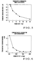
- Fig. 5 is a graph showing a frame rate vs. degradation index characteristic representing the influence component on the subjective video quality by the frame rate fr.
- the abscissa represents the frame rate fr (fps), and the ordinate represents the frame rate degradation index ⁇ 1 (fr). Along with the increase in frame rate, the frame rate degradation index ⁇ 1 (fr) monotonically decreases.
- Fig. 6 is a graph showing a coding bit rate vs. degradation index characteristic representing the influence component on the subjective video quality by the coding bit rate br.
- the abscissa represents the coding bit rate br (bps), and the ordinate represents the coding bit rate degradation index ⁇ 2 (br).
- the coding bit rate degradation index ⁇ 2 (br) monotonically decreases.
- the degradation model 22 i.e., the packet loss rate vs. video quality degradation ratio characteristic corresponding to the estimation conditions 10 can be determined.
- Fig. 7 is a three-dimensional graph showing a degradation index.
- the first abscissa represents the frame rate fr
- the second abscissa represents the coding bit rate br
- the ordinate represents the degradation index ⁇ (fr,br).
- Fig. 8 is a graph showing a packet loss rate vs. video quality degradation ratio characteristic (with respect to the frame rate).
- the abscissa represents the packet loss rate pl (%)
- the ordinate represents the video quality degradation ratio P(fr,br,pl).
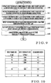
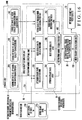
- Fig. 9 is a flowchart illustrating the video quality estimation process of the video quality estimation apparatus according to the first embodiment of the present invention.
- the video quality estimation apparatus 1 starts the video quality estimation process in Fig. 9 in accordance with an instruction operation from the operator or input of the estimation conditions 10.
- the estimation conditions 10 designate the reference subjective video quality 23 together with the main parameters 21.
- the above-described frame rate vs. degradation index characteristic 31A ( Fig. 5 ) and coding bit rate vs. degradation index characteristic 31B ( Fig. 6 ) are prepared in advance and stored in the storage unit 31M as function expressions.
- the parameter extraction unit 11 extracts the various estimation conditions 10 related to an evaluation target audiovisual communication service, extracts a frame rate and a coding bit rate related to encoding of an audiovisual medium from the estimation conditions 10, extracts a packet loss rate of the audiovisual medium in the communication network or terminal, and outputs the input frame rate fr (21A), input coding bit rate br (21B), and input packet loss rate pl (21C) as the main parameters 21 (step S100).
- the degradation model specifying unit 12 specifies the degradation model 22 representing the relationship between the packet loss rate and the subjective video quality of the audiovisual medium on the basis of the input frame rate 21A and input coding bit rate 21B of the main parameters 21 output from the parameter extraction unit 11.
- the frame rate degradation index calculation unit 12A calculates the frame rate degradation index ⁇ 1 (fr) (32A) corresponding to the input frame rate fr (21A) by referring to the frame rate vs. degradation index characteristic 31A, as shown in Fig. 5 , in the storage unit 31M (step S101).
- the degradation model specifying unit 12 causes the coding bit rate degradation index calculation unit 12B to calculate the coding bit rate degradation index ⁇ 2 (br) (32B) corresponding to the input coding bit rate br (21B) by referring to the coding bit rate vs. degradation index characteristic 31B, as shown in Fig. 6 , in the storage unit 31M (step S102).
- the degradation model specifying unit 12 causes the degradation index calculation unit 12C to substitute the actual values of the frame rate degradation index ⁇ 1 (fr) and coding bit rate degradation index ⁇ 2 (br) into equation (3) described above, thereby calculating the degradation index ⁇ (fr,br) (33) (step S103).
- the degradation model 22 shown in Fig. 8 i.e., the packet loss rate vs. video quality degradation ratio characteristic expressed by equation (2) described above is specified.
- the video quality estimation apparatus 1 causes the video quality correction unit 13 to substitute the degradation index ⁇ (fr,br) and the input packet loss rate pl (21C) of the main parameters 21 output from the parameter extraction unit 11 into equation (2) described above by referring to the degradation model 22 specified by the degradation model specifying unit 12, thereby calculating the corresponding video quality degradation ratio P(fr,br,pl) (step S104).
- the video quality correction unit 13 substitutes the actual value of the video quality degradation ratio P(fr,br,pl) and the reference subjective video quality 23 into equation (1) described above, thereby calculating the video quality MOS(fr,br,pl).
- the video quality correction unit 13 outputs the video quality as the subjective video quality estimation value 24 a viewer actually senses from the audiovisual medium reproduced on the terminal by using the evaluation target audiovisual communication service (step S105), and finishes the series of video quality estimation processes.
- the degradation model specifying unit 12 specifies the degradation model 22 representing the relationship between the packet loss rate and the degradation in the reference subjective video quality 23 on the basis of the input frame rate 21A and input coding bit rate 21B.
- the desired subjective video quality estimation value 24 is calculated by correcting the reference subjective video quality on the basis of the video quality degradation ratio corresponding to the input packet loss rate 21C calculated by using the degradation model 22.
- the video quality estimation apparatus 1 of this embodiment enables to grasp a specific packet loss rate that is allowable in transferring an audiovisual medium encoded at a coding bit rate and a frame rate while satisfying the desired video quality.
- the coding bit rate is often limited by the constraints of a network.
- the coding bit rate is fixed, and the video quality estimation apparatus 1 of this embodiment is applied. This makes it possible to easily and specifically grasp the relationship between the frame rate, packet loss rate, and video quality.
- the frame rate vs. degradation index characteristic 31A and coding bit rate vs. degradation index characteristic 31B used to calculate the degradation index 33 are prepared in the form of function expressions in advance.
- the degradation index derivation characteristics 31 used to derive the degradation index 33 are not limited to function expressions. They may be stored in the storage unit 31M as values corresponding to the input frame rate and input coding bit rate.
- Fig. 10 is a view showing a structural example of degradation index information representing the correlation between the input frame rate, the input coding bit rate, and the degradation index.
- Each degradation index information contains a set of the input frame rate fr (21A) and input coding bit rate br (21B) and corresponding degradation index ⁇ (fr,br) (33).
- the degradation index information is calculated on the basis of the degradation index derivation characteristics 31 and stored in the storage unit 31M in advance.
- the degradation model specifying unit 12 may derive the degradation index ⁇ (fr,br) corresponding to the input frame rate 21A and input coding bit rate 21B by referring to the degradation index information.
- the video quality degradation ratio P(fr,br,pl) corresponding to the degradation index ⁇ (fr,br) is calculated by using equation (2) described above.
- the video quality degradation ratio P(fr,br,pl) may be calculated by using any other calculation formula.
- This calculation is suitable when, for example, the video quality degradation ratio P(fr,br,pl) steeply decreases along with the increase in packet loss rate pl.
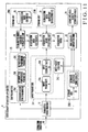
- FIG. 11 is a block diagram showing the arrangement of a video quality estimation apparatus according to the second embodiment of the present invention.
- the same reference numerals as in Fig. 1 described above denote the same or similar parts in Fig. 11 .
- Fig. 12 is a block diagram showing the arrangement of the estimation model specifying unit of the video quality estimation apparatus according to the second embodiment of the present invention.
- the same reference numerals as in Fig. 2 described above denote the same or similar parts in Fig. 12 .
- the first embodiment has exemplified a case in which the degradation index 33 corresponding to the input frame rate 21A and input coding bit rate 21B is derived by referring to the degradation index derivation characteristics 31 prepared in advance.
- the second embodiment a case will be described in which degradation index derivation characteristics 31 corresponding to various estimation conditions 10 related to an evaluation target audiovisual communication service are sequentially specified on the basis of, of the estimation conditions 10, the communication type of the audiovisual communication service, the reproduction performance of a terminal that reproduces an audiovisual medium, or the reproduction environment of a terminal that reproduces an audiovisual medium.
- a video quality estimation apparatus 1 additionally includes a degradation index coefficient extraction unit 14 and a degradation index coefficient database (to be referred to as a degradation index coefficient DB hereinafter) 26.
- the degradation index coefficient extraction unit 14 has a function of extracting degradation index coefficients 27 corresponding to sub parameters 25 extracted by a parameter extraction unit 11 from the estimation conditions 10 by referring to the degradation index coefficient DB 26 in a storage unit 26M (third storage unit).
- Fig. 13 is an explanatory view showing an arrangement of the degradation index coefficient DB.
- the degradation index coefficient DB 26 is a database showing sets of the various sub parameters 25 and corresponding characteristic coefficients a , b, c,..., i (27).
- the sub parameters 25 include a communication type parameter 25A indicating the communication type of an audiovisual communication service, a reproduction performance parameter 25B indicating the reproduction performance of a terminal that reproduces an audiovisual medium, and a reproduction environment parameter 25C indicating the reproduction environment of a terminal that reproduces an audiovisual medium.
- a detailed example of the communication type parameter 25A is "task" that indicates a communication type executed by an evaluation target audiovisual communication service.
- reproduction performance parameter 25B are "encoding method”, "video format”, and “key frame” related to encoding of an audiovisual medium and "monitor size” and “monitor resolution” related to the medium reproduction performance of a terminal.
- a detailed example of the reproduction environment parameter 25C is "indoor luminance" in reproducing a medium on a terminal.
- the sub parameters 25 are not limited to these examples. They can arbitrarily be selected in accordance with the contents of the evaluation target audiovisual communication service or audiovisual medium and need only include at least one of the communication type parameter 25A, reproduction performance parameter 25B, and reproduction environment parameter 25C.
- the degradation index coefficient extraction unit 14 extracts the degradation index coefficients 27 corresponding to the sub parameters 25 by referring to the degradation index coefficient DB 26 in the storage unit 26M prepared in advance.
- the degradation index coefficients 27 are coefficients to specify the degradation index derivation characteristics 31 to be used to derive a degradation index 33.
- a degradation model specifying unit 12 specifies the degradation index derivation characteristics 31, i.e., frame rate vs. degradation index characteristic 31A and coding bit rate vs. degradation index characteristic 31B specified by the degradation index coefficients 27 extracted by the degradation index coefficient extraction unit 14.
- the degradation index derivation characteristics 31 used by the degradation model specifying unit 12 will be described next in detail.
- the degradation index derivation characteristics 31 can be modeled in the following way by using the degradation index coefficients 27 extracted by the degradation index coefficient extraction unit 14 from the degradation index coefficient DB 26.
- the frame rate vs. degradation index characteristic 31A of the degradation index derivation characteristics 31 tends to monotonically decrease the frame rate degradation index along with the increase in frame rate and then converge to a certain minimum value, as shown in Fig. 5 described above.
- the coding bit rate vs. degradation index characteristic 31B of the degradation index derivation characteristics 31 tends to decrease the coding bit rate degradation index along with the increase in coding bit rate and then converge to a certain minimum value, as shown in Fig. 6 described above.
- Modeling of the degradation index derivation characteristics 31 need not always be done by using the above-described exponential function. Any other function may be used. For example, depending on the contents of the evaluation target audiovisual communication service or audiovisual medium, the network performance, or the contents of the estimation conditions 10, a video quality estimation process based on an input coding bit rate or input frame rate within a relatively limited range suffices. If such local estimation is possible, the degradation index derivation characteristics 31 can be modeled by a simple function such as a linear function, as described above.
- Fig. 14 is a flowchart illustrating the video quality estimation process of the video quality estimation apparatus according to the second embodiment of the present invention.
- the same step numbers as in Fig. 9 described above denote the same or similar steps in Fig. 14 .
- the video quality estimation apparatus 1 starts the video quality estimation process in Fig. 9 in accordance with an instruction operation from the operator or input of the estimation conditions 10.
- the communication type parameter 25A, reproduction performance parameter 25B, and reproduction environment parameter 25C are used as the sub parameters 25.
- the degradation index coefficient DB 26 in the storage unit 26M stores the sets of the sub parameters 25 and degradation index coefficients 27 in advance.
- the parameter extraction unit 11 extracts the various estimation conditions 10 related to an evaluation target audiovisual communication service, extracts a frame rate and a coding bit rate related to encoding of an audiovisual medium from the estimation conditions 10, extracts a packet loss rate of the audiovisual medium in the communication network or terminal, and outputs the input frame rate fr (21A), input coding bit rate br (21B), and input packet loss rate pl (21C) as main parameters 21 (step S100).
- the parameter extraction unit 11 also extracts the communication type parameter 25A, reproduction performance parameter 25B, and reproduction environment parameter 25C from the estimation conditions 10 and outputs them as the sub parameters 25 (step S200).
- the degradation index coefficient extraction unit 14 extracts and outputs the degradation index coefficients a , b,..., i (27) corresponding to the values of the sub parameters 25 by referring to the degradation index coefficient DB 26 in the storage unit 26M (step S201).
- the degradation model specifying unit 12 causes a frame rate degradation index calculation unit 12A to calculate a frame rate degradation index ⁇ 1 (fr) (32A) corresponding to the input frame rate fr (21A) by referring to the frame rate vs. degradation index characteristic 31A which is specified by the coefficients d, e, and f of the degradation index coefficients 27 (step S101).
- the degradation model specifying unit 12 causes a coding bit rate degradation index calculation unit 12B to calculate a coding bit rate degradation index ⁇ 2 (br) (32B) corresponding to the input coding bit rate br (21B) by referring to the coding bit rate vs. degradation index characteristic 31B which is specified by the coefficients g, h, and i of the degradation index coefficients 27 (step S102).
- the degradation model specifying unit 12 calculates the degradation index ⁇ (fr,br) (33) by equation (3) described above using the frame rate degradation index ⁇ 1 (fr), coding bit rate degradation index ⁇ 2 (br), and the coefficients a , b, and c of the degradation index coefficients 27, thereby specifying the degradation model 22 (step S103).
- the video quality estimation apparatus 1 causes a video quality correction unit 13 to calculate the video quality degradation ratio P(fr,br,pl) corresponding to the degradation index ⁇ (fr,br) and input packet loss rate pl (21C) by referring to the degradation model 22 specified by the degradation model specifying unit 12 in the same way as described above (step S104).
- the video quality correction unit 13 calculates video quality MOS(fr,br,pl) on the basis of the video quality degradation ratio P(fr,br,pl) and reference subjective video quality 23, outputs it as a subjective video quality estimation value 24 a viewer actually senses from the audiovisual medium reproduced on the terminal by using the evaluation target audiovisual communication service (step S105), and finishes the series of video quality estimation processes.
- the degradation index coefficient extraction unit 14 extracts, from the degradation index coefficient DB 26 in the storage unit 26M, the degradation index coefficients 27 corresponding to the sub parameters 25 which are extracted by the parameter extraction unit 11 and include at least one of the communication type parameter 25A, reproduction performance parameter 25B, and reproduction environment parameter 25C.
- the degradation model specifying unit 12 calculates the degradation index 33 corresponding to the input frame rate 21A and input coding bit rate 21B on the basis of the degradation index derivation characteristics 31 specified by the degradation index coefficients 27. It is therefore possible to derive the degradation index 33 based on the specific properties of the evaluation target audiovisual communication service or terminal. This improves the video quality estimation accuracy.
- a degradation model needs to be prepared for each encoding method, communication network, or terminal used in an evaluation target audiovisual communication service.
- the degradation model 22 does not depend on the encoding method, communication network, or terminal.
- the same degradation model can be used only by referring to the degradation index coefficients to be used in the degradation model in accordance with the encoding method communication network, or terminal. It is therefore possible to flexibly cope with audiovisual communication services in different environments.
- FIG. 15 is a block diagram showing the arrangement of a video quality estimation apparatus according to the third embodiment of the present invention.
- the same reference numerals as in Fig. 1 described above denote the same or similar parts in Fig. 15 .
- Fig. 16 is a block diagram showing the arrangement of the estimation model specifying unit of the video quality estimation apparatus according to the third embodiment of the present invention.
- the same reference numerals as in Fig. 2 described above denote the same or similar parts in Fig. 16 .
- the first and second embodiments have exemplified a case in which the reference subjective video quality 23 is designated by the estimation conditions 10 and stored in the storage unit 23M in advance.
- a video quality estimation apparatus 1 incorporates a video quality estimation unit 15, and a reference subjective video quality 23 is estimated on the basis of an input frame rate 21A and an input coding bit rate 21B of main parameters 21 designated by estimation conditions 10.
- an estimation model representing the relationship between the frame rate and the reference subjective video quality of the audiovisual medium is specified on the basis of the input coding bit rate.
- Reference subjective video quality corresponding to the input frame rate is estimated by using the specified estimation model and output.
- the arrangement of causing a video quality correction unit 13 to obtain a subjective video quality estimation value 24 by correcting the reference subjective video quality 23 on the basis of a degradation model 22 is the same as in the above-described first embodiment, and a detailed description thereof will not be repeated here.
- the second embodiment may be used in place of the first embodiment.
- the video quality estimation apparatus 1 additionally includes the video quality estimation unit 15.
- the video quality estimation unit 15 also includes several functional units, as shown in Fig. 16 .
- the main functional units include an estimation model specifying unit 15A and a video quality calculation unit 15B.
- the estimation model specifying unit 15A has a function of calculating estimation model specifying parameters 35 to specify an estimation model 36 representing the relationship between the frame rate and subjective video quality of an audiovisual medium on the basis of the input coding bit rate 21B of the main parameters 21 output from a parameter extraction unit 11.
- the video quality calculation unit 15B has a function of estimating subjective video quality corresponding to the input frame rate 21A of the main parameters 21 and outputting it as the desired reference subjective video quality 23 by referring to the estimation model 36 specified by the estimation model specifying unit 15A.
- the estimation model specifying unit 15A also includes several functional units, as shown in Fig. 16 .
- the main functional units for calculating the estimation model specifying parameters 35 include an optimum frame rate calculation unit 16A, best video quality calculation unit 16B, video quality degradation index calculation unit 16C, and estimation model generation unit 16D.
- the estimation model specifying parameters 35 are values which specify the shapes of functions to be used as the estimation model 36. In this embodiment, at least the optimum frame rate and best video quality to be described below are used as the estimation model specifying parameters 35. Another parameter represented by a video quality degradation index may be added to the estimation model specifying parameters 35.
- the optimum frame rate calculation unit 16A has a function of calculating, as one of the estimation model specifying parameters 35, an optimum frame rate ofr(br) (35A) representing a frame rate corresponding to the best subjective video quality of an audiovisual medium transmitted at the input coding bit rate br (21B) by referring to a coding bit rate vs. optimum frame rate characteristic 34A in a storage unit 34M.
- the best video quality calculation unit 16B has a function of calculating, as one of the estimation model specifying parameters 35, best video quality ⁇ (br) (35B) representing the best value of the subjective video quality of an audiovisual medium transmitted at the input coding bit rate 21B by referring to a coding bit rate vs. best video quality characteristic 34B in the storage unit 34M.
- the video quality degradation index calculation unit 16C has a function of calculating, as one of the estimation model specifying parameters 35, a video quality degradation index ⁇ (br) (35C) representing the degree of degradation from the best video quality 35B representing the best value of the subjective video quality of an audiovisual medium transmitted at the input coding bit rate 21B by referring to a coding bit rate vs. video quality degradation index characteristic 34C in the storage unit 34M.
- the coding bit rate vs. optimum frame rate characteristic 34A, coding bit rate vs. best video quality characteristic 34B, and coding bit rate vs. video quality degradation index characteristic 34C are prepared as estimation model specifying parameter derivation characteristics 34 and stored in the storage unit 34M in advance.
- the estimation model generation unit 16D has a function of generating the estimation model 36 to estimate subjective video quality corresponding to the input frame rate 21A of the main parameters 21 by substituting, into a predetermined function expression, the values of the estimation model specifying parameters 35 including the optimum frame rate ofr(br) calculated by the optimum frame rate calculation unit 16A, the best video quality ⁇ (br) calculated by the best video quality calculation unit 16B, and the video quality degradation index ⁇ (br) calculated by the video quality degradation index calculation unit 16C.
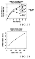
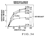
- Fig. 17 is a graph showing the frame rate vs. subjective video quality characteristic of an audiovisual communication medium in an audiovisual communication service.
- the abscissa represents a frame rate fr (fps)
- the ordinate represents a subjective video quality value MOS(fr,br) (MOS value).
- Fig. 17 shows characteristics corresponding to the respective coding bit rates br.
- the number of coding bits per unit frame and the frame rate have a tradeoff relationship with respect to the subjective video quality of an audiovisual medium.
- the temporal video quality can be improved because a smooth video image is obtained.
- spatial image degradation may become noticeable because of the decrease in the number of coding bits per unit frame, resulting in poor video quality.
- spatial image degradation improves so that a higher video quality can be obtained.
- temporal frame drop with a jerky effect may take place, resulting in poor video quality.
- the subjective video quality characteristic exhibits a similar shape even when the coding bit rate changes.
- the coordinate position of each subjective video quality characteristic can be specified by its vertex, i.e., estimation model specifying parameters including the optimum frame rate and best video quality.
- the estimation model specifying unit 15A specifies the estimation model 36 representing the relationship between the frame rate and the subjective video quality of an audiovisual medium on the basis of the input coding bit rate 21B.
- the video quality calculation unit 15B estimates the reference subjective video quality 23 corresponding to the input frame rate 21A by using the estimation model 36 specified by the estimation model specifying unit 15A.
- estimation model specifying unit 15A To cause the estimation model specifying unit 15A to specify the estimation model 36 representing the relationship between the frame rate and the subjective video quality of an audiovisual medium on the basis of the input coding bit rate 21B, it is necessary to derive the optimum frame rate 35A and best video quality 35B as estimation model specifying parameters corresponding to the input coding bit rate 21B.
- the coding bit rate vs. optimum frame rate characteristic 34A and coding bit rate vs. best video quality characteristic 34B to be described below are prepared in advance as the estimation model specifying parameter derivation characteristics 34.
- the estimation model specifying parameters 35 corresponding to the input coding bit rate 21B are derived by referring to these characteristics.
- the coding bit rate when the audiovisual medium is reproduced with the best video quality and the frame rate at that time i.e., optimum frame rate have such a relationship that the optimum frame rate monotonically increases along with the increase in coding bit rate and then converges to the maximum frame rate.
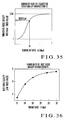
- Fig. 18 is a graph showing the coding bit rate vs. optimum frame rate characteristic.
- the abscissa represents a coding bit rate br (kbps), and the ordinate represents an optimum frame rate ofr(br) (fps).
- the coding bit rate when the audiovisual medium is transmitted at the optimum frame rate and the video quality i.e., best video quality have a relationship with such a tendency that the video quality becomes high along with the increase in coding bit rate and then converges to a maximum value (maximum subjective video quality value) or becomes low along with the decrease in coding bit rate and then converges to a minimum value.
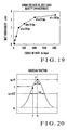
- Fig. 19 is a graph showing the coding bit rate vs. best video quality characteristic.
- the abscissa represents the coding bit rate br (kbps), and the ordinate represents the best video quality ⁇ (br).
- Video quality is expressed by the MOS value which uses "1" as a reference value and can take "5" at maximum.
- the best video quality ⁇ (br) of the estimation model 36 uses "0" as a reference value and can take "4" at maximum. Although the reference values are different, these values use almost the same scale and therefore will not particularly be distinguished below.
- this coding bit rate vs. best video quality characteristic even when a high coding bit rate is set, the video quality is saturated at a certain coding bit rate. This matches the human visual characteristic and, more particularly, even when the coding bit rate is increased more than necessary, no viewer can visually detect the improvement of video quality. If the coding bit rate is too low, video quality conspicuously degrades and consequently converges to the minimum video quality. This matches an actual phenomenon and, more specifically, in a video image containing, e.g., a human face moving in the screen, the outlines of eyes and nose become blurred and flat so the viewer cannot recognize the face itself.
- estimation model used by the estimation model specifying unit 15A of the video quality estimation unit 15 and the method of specifying the estimation model will be described next in detail.
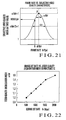
- a convex function having a vertex corresponding to the optimum frame rate 35A and best video quality 35B as the estimation model specifying parameters 35 can be expressed by using a Gaussian function as shown in Fig. 20.
- Fig. 20 is an explanatory view showing a Gaussian function.
- the Gaussian function exhibits a convex shape which has a vertex P corresponding to the maximum value and attenuates from there to the both sides.
- the function expression is given by the x-coordinate of the vertex P and the maximum amplitude.
- x c be the x-coordinate of the vertex P
- A be the maximum amplitude
- y 0 be the reference value (minimum value) of the Y-axis
- ⁇ be the coefficient representing the spread width of the convex characteristic.
- variable x be the logarithmic value of the frame rate of the audiovisual medium
- function value y be the subjective video quality
- variable x of the vertex P be the logarithmic value of the optimum frame rate corresponding to the coding bit rate
- maximum amplitude A be the best video quality ⁇ (br) corresponding to the coding bit rate.
- Fig. 21 is an explanatory view showing a frame rate vs. subjective video quality characteristic modeled by the Gaussian function.
- the spread width of the convex characteristic is specified by using the coefficient ⁇ . If it is necessary to change the spread width in correspondence with each frame rate vs. subjective video quality characteristic corresponding to a coding bit rate, the video quality degradation index ⁇ (br) (35C) corresponding to the coding bit rate is used.
- the video quality degradation index ⁇ (br) indicates the degree of degradation from the best video quality 35B representing the best value of the subjective video quality of an audiovisual medium transmitted at the input coding bit rate 21B.
- the video quality degradation index ⁇ (br) corresponds to the coefficient ⁇ of the Gaussian function.
- the coding bit rate and the degree of degradation of subjective video quality have such a relationship that the degree of degradation becomes smooth as the coding bit rate increases, while the degree of degradation becomes large as the coding bit rate decreases.
- the coding bit rate and the video quality degradation index have a relationship with such a tendency that as the coding bit rate becomes high, the spread width of the convex shape of the frame rate vs. subjective video quality characteristic becomes large, and the video quality degradation index also becomes large.
- the coding bit rate becomes low, the spread width of the convex shape of the frame rate vs. subjective video quality characteristic becomes small, and the video quality degradation index also becomes small.
- Fig. 22 is a graph showing the coding bit rate vs. video quality degradation index characteristic.
- the abscissa represents the coding bit rate br (kbps), and the ordinate represents the video quality degradation index ⁇ (br).
- Fig. 22 shows a coding bit rate vs. video quality degradation index characteristic in an estimation model expressed by a Gaussian function. If another estimation model is used, a coding bit rate vs. video quality degradation index characteristic representing a coefficient corresponding to the estimation model is used.
- Fig. 23 is a flowchart illustrating the reference subjective video quality estimation process of the video quality estimation apparatus according to the third embodiment of the present invention.
- the video quality estimation apparatus 1 starts the reference subjective video quality estimation process in Fig. 23 in accordance with an instruction operation from the operator or input of the estimation conditions 10.
- An example will be described here in which the video quality degradation index 35C is used as an estimation model specifying parameter in addition to the optimum frame rate 35A and best video quality 35B.
- the above-described coding bit rate vs. optimum frame rate characteristic 34A ( Fig. 18 ), coding bit rate vs. best video quality characteristic 34B ( Fig. 19 ), and coding bit rate vs. video quality degradation index characteristic 34C ( Fig. 22 ) are prepared in advance and stored in the storage unit 34M as function expressions.
- the estimation model specifying unit 15A of the video quality estimation unit 15 acquires, from the storage unit (not shown), the input frame rate fr (21A) and input coding bit rate br (21B) which are extracted from the estimation conditions 10 by the parameter extraction unit 11 (step S300).
- the estimation model specifying unit 15A specifies the estimation model 36 representing the relationship between the frame rate and the subjective video quality of the audiovisual medium on the basis of the input coding bit rate br (21B).
- the optimum frame rate calculation unit 16A calculates the optimum frame rate ofr(br) (35A) corresponding to the input coding bit rate br (21B) by referring to the coding bit rate vs. optimum frame rate characteristic 34A in the storage unit 34M (step S301).
- the estimation model specifying unit 15A causes the best video quality calculation unit 16B to calculate the best video quality ⁇ (br) (35B) corresponding to the input coding bit rate br (21B) by referring to the coding bit rate vs. best video quality characteristic 34B in the storage unit 34M (step S302).
- the estimation model specifying unit 15A causes the video quality degradation index calculation unit 16C to calculate the video quality degradation index ⁇ (br) (35C) corresponding to the input coding bit rate br (21B) by referring to the coding bit rate vs. video quality degradation index characteristic 34C in the storage unit 34M (step S303).
- the estimation model specifying unit 15A causes the estimation model generation unit 16D to substitute the actual values of the estimation model specifying parameters 35 including the optimum frame rate ofr(br), best video quality ⁇ (br), and video quality degradation index ⁇ (br) into equation (12) described above, thereby specifying the estimation model MOS(fr,br), i.e., frame rate vs. subjective video quality characteristic (step S304).
- the video quality estimation apparatus 1 causes the video quality calculation unit 15B of the video quality estimation unit 15 to calculate video quality corresponding to the input frame rate 21A of the main parameters 21 output from the parameter extraction unit 11 by referring to the estimation model 36 specified by the estimation model specifying unit 15A, outputs the video quality as the reference subjective video quality 23 representing subjective video quality a viewer actually senses from the audiovisual medium reproduced on the terminal by using the evaluation target audiovisual communication service (step S305), and finishes the series of reference subjective video quality estimation processes.
- the estimation model specifying unit 15A specifies the estimation model 36 representing the relationship between the frame rate and the subjective video quality of the audiovisual medium on the basis of the input coding bit rate 21B.
- Subjective video quality corresponding to the input frame rate 21A is estimated by using the specified estimation model 36 and output as the reference subjective video quality 23.
- the video quality correction unit 13 described in the first or second embodiment can estimate the subjective video quality estimation value 24 corresponding to the arbitrary estimation conditions 10 without preparing the reference subjective video quality 23.
- the coding bit rate vs. optimum frame rate characteristic 34A, coding bit rate vs. best video quality characteristic 34B, and coding bit rate vs. video quality degradation index characteristic 34C used to calculate the estimation model specifying parameters 35 are prepared in the form of function expressions and stored in the storage unit 34M in advance.
- the estimation model specifying parameter derivation characteristics 34 used to calculate the estimation model specifying parameters are not limited to function expressions. They may be stored in the storage unit 34M as values corresponding to the input coding bit rate.
- Fig. 24 is a view showing a structural example of estimation model specifying parameter information representing the correlation between the input coding bit rate and the estimation model specifying parameters.
- Each estimation model specifying parameter information contains a set of the input coding bit rate br (21B) and corresponding optimum frame rate ofr(br) (35A), best video quality ⁇ (br) (35B), and video quality degradation index ⁇ (br) (35C).
- the estimation model specifying parameter information is calculated on the basis of the estimation model specifying parameter derivation characteristics 34 and stored in the storage unit 131M in advance.
- the estimation model specifying parameters 35 corresponding to the input coding bit rate 21B may be derived by referring to the estimation model specifying parameter information.
- FIG. 25 is a block diagram showing the arrangement of a video quality estimation apparatus according to the fourth embodiment of the present invention.
- the same reference numerals as in Fig. 15 described above denote the same or similar parts in Fig. 25 .
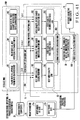
- Fig. 26 is a block diagram showing the arrangement of the estimation model specifying unit of the video quality estimation apparatus according to the fourth embodiment of the present invention.
- the same reference numerals as in Fig. 16 described above denote the same or similar parts in Fig. 26 .
- the third embodiment has exemplified a case in which the estimation model specifying parameters 35 corresponding to an input coding bit rate are derived by referring to the estimation model specifying parameter derivation characteristics 34 prepared in advance.
- estimation model specifying parameter derivation characteristics 34 corresponding to various estimation conditions 10 related to an evaluation target audiovisual communication service are sequentially specified on the basis of, of the estimation conditions 10, the communication type of the audiovisual communication service, the reproduction performance of a terminal that reproduces an audiovisual medium, or the reproduction environment of a terminal that reproduces an audiovisual medium, instead of preparing the estimation model specifying parameter derivation characteristics 34 in advance.
- a video quality estimation apparatus 1 additionally includes a characteristic coefficient extraction unit 17 and a characteristic coefficient database (to be referred to as a characteristic coefficient DB hereinafter) 28.
- the characteristic coefficient extraction unit 17 has a function of extracting characteristic coefficients 29 corresponding to sub parameters 25 extracted by a parameter extraction unit 11 from the estimation conditions 10 by referring to the characteristic coefficient DB 28 in a storage unit 28M (fourth storage unit).
- the sub parameters 25 used in this embodiment are the same as those described in the second embodiment, and a detailed description thereof will not be repeated here.
- Fig. 27 is an explanatory view showing an arrangement of the characteristic coefficient DB.
- the characteristic coefficient DB 28 is a database showing sets of the various sub parameters 25 and corresponding characteristic coefficients j, k,..., p (29).
- the sub parameters 25 include a communication type parameter 25A indicating the communication type of an audiovisual communication service, a reproduction performance parameter 25B indicating the reproduction performance of a terminal that reproduces an audiovisual medium, and a reproduction environment parameter 25C indicating the reproduction environment of a terminal that reproduces an audiovisual medium.
- the sub parameters 25 are not limited to these examples. They can arbitrarily be selected in accordance with the contents of the evaluation target audiovisual communication service or audiovisual medium and need only include at least one of the communication type parameter 25A, reproduction performance parameter 25B, and reproduction environment parameter 25C.
- the characteristic coefficient extraction unit 17 extracts the characteristic coefficients 29 corresponding to the sub parameters 25 by referring to the characteristic coefficient DB 28 prepared in advance.
- the characteristic coefficients 29 are coefficients to specify the estimation model specifying parameter derivation characteristics to be used to derive estimation model specifying parameters 35.
- An estimation model specifying unit 15A specifies the estimation model specifying parameter derivation characteristics 34, i.e., coding bit rate vs. optimum frame rate characteristic 34A, coding bit rate vs. best video quality characteristic 34B, and coding bit rate vs. video quality degradation index characteristic 34C specified by the characteristic coefficients 29 extracted by the characteristic coefficient extraction unit 17.
- the estimation model specifying parameter derivation characteristics 34 used by the estimation model specifying unit 15A will be described next in detail.
- the estimation model specifying parameter derivation characteristics 34 can be modeled in the following way by using the characteristic coefficients 29 extracted by the characteristic coefficient extraction unit 17 from the characteristic coefficient DB 28.
- the coding bit rate vs. optimum frame rate characteristic 34A of the estimation model specifying parameter derivation characteristics 34 tends to monotonically increase the optimum frame rate along with the increase in coding bit rate and then converge to a certain maximum frame rate, as shown in Fig. 18 described above.
- the coding bit rate vs. best video quality characteristic 34B of the estimation model specifying parameter derivation characteristics 34 tends to increase the video quality along with the increase in coding bit rate and then converge to a certain maximum value and decrease the video quality along with the decrease in coding bit rate and then converge to a certain minimum value, as shown in Fig. 19 described above.
- the coding bit rate vs. best video quality characteristic 34B can be modeled by, e.g., a general logistic function.
- Fig. 28 is an explanatory view showing a logistic function.
- a logistic function monotonically increases a function value y along with the increase in variable x when coefficient p > 1.
- the function value y converges to the minimum value.
- the function value y converges to the maximum value.
- a 1 be the minimum value
- a 2 be the maximum value
- p and x 0 be coefficients.
- the function value y with respect to the arbitrary variable x is given by equation (14) including a term of the maximum value A 2 and a fraction term representing the decrease from the maximum value A 2 .
- y A 2 + A 1 ⁇ A 2 1 + x / x 0 P
- the coding bit rate vs. video quality degradation index characteristic 34C of the estimation model specifying parameter derivation characteristics 34 tends to increase the video quality degradation index along with the increase in coding bit rate and decrease the video quality degradation index along with the decrease in coding bit rate, as shown in Fig. 22 described above.
- Modeling of the estimation model specifying parameter derivation characteristics 34 need not always be done by using the above-described linear function or logistic function. Any other function may be used. For example, depending on the contents of the evaluation target audiovisual communication service or audiovisual medium, the network performance, or the contents of the estimation conditions 10, a video quality estimation process based on an input coding bit rate or input frame rate within a relatively limited range suffices. If such local estimation is possible, the estimation model specifying parameter derivation characteristics 34 can be modeled by a simple function such as a linear function, as described above.
- the coding bit rate vs. optimum frame rate characteristic 34A may be expressed by using another function such as an exponential function.
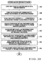
- Fig. 30 is a flowchart illustrating the reference subjective video quality estimation process of the video quality estimation apparatus according to the fourth embodiment of the present invention.
- the same step numbers as in Fig. 23 described above denote the same or similar steps in Fig. 30 .
- the video quality estimation apparatus 1 starts the reference subjective video quality estimation process in Fig. 30 in accordance with an instruction operation from the operator or input of the estimation conditions 10.
- An example will be described here in which a video quality degradation index 35C is used as an estimation model specifying parameter in addition to an optimum frame rate 35A and a best video quality 35B.
- the communication type parameter 25A, reproduction performance parameter 25B, and reproduction environment parameter 25C are used as the sub parameters 25.
- the characteristic coefficient DB 28 stores the sets of the sub parameters 25 and characteristic coefficients 29 in advance.
- the estimation model specifying unit 15A acquires, from the storage unit (not shown), an input frame rate fr (21A) and an input coding bit rate br (21B) of main parameters 21 extracted from the estimation conditions 10 by the parameter extraction unit 11 (step S300).
- the characteristic coefficient extraction unit 17 extracts, from the storage unit (not shown), the communication type parameter 25A, reproduction performance parameter 25B, and reproduction environment parameter 25C of the sub parameters 25 extracted from the estimation conditions 10 by the parameter extraction unit 11 (step S400).
- the characteristic coefficient extraction unit 17 extracts and outputs the characteristic coefficients j, k, l,..., p (29) corresponding to the values of the sub parameters 25 by referring to the characteristic coefficient DB 28 in the storage unit 28M (step S401).
- the estimation model specifying unit 15A causes an optimum frame rate calculation unit 16A to calculate the optimum frame rate ofr(br) (35A) corresponding to the input coding bit rate br (21B) by referring to, from the storage unit 34M, the coding bit rate vs. optimum frame rate characteristic 34A which is specified by the characteristic coefficients j and k of the characteristic coefficients 29 (step S301).
- the estimation model specifying unit 15A causes a best video quality calculation unit 16B to calculate the best video quality ⁇ (br) (35B) corresponding to the input coding bit rate br (21B) by referring to, from the storage unit 34M, the coding bit rate vs. best video quality characteristic 34B which is specified by the characteristic coefficients l, m, and n of the characteristic coefficients 29 (step S302).
- the estimation model specifying unit 15A causes a video quality degradation index calculation unit 16C to calculate the video quality degradation index ⁇ (br) (35C) corresponding to the input coding bit rate br (21B) by referring to, from the storage unit 34M, the coding bit rate vs. video quality degradation index characteristic 34C which is specified by the characteristic coefficients o and p of the characteristic coefficients 29 (step S303).
- the estimation model specifying unit 15A causes an estimation model generation unit 16D to substitute the actual values of the estimation model specifying parameters 35 including the optimum frame rate ofr(br), best video quality ⁇ (br), and video quality degradation index ⁇ (br) into equation (12) described above, thereby specifying an estimation model MOS(fr,br), i.e., frame rate vs. subjective video quality characteristic (step S304).
- an estimation model MOS(fr,br) i.e., frame rate vs. subjective video quality characteristic
- the video quality estimation apparatus 1 causes a video quality calculation unit 15B to calculate video quality corresponding to the input frame rate 21A of the main parameters 21 output from the parameter extraction unit 11 by referring to an estimation model 36 specified by the estimation model specifying unit 15A, outputs the video quality as a subjective video quality estimation value 24 a viewer actually senses from the audiovisual medium reproduced on the terminal by using the evaluation target audiovisual communication service (step S305), and finishes the series of reference subjective video quality estimation processes.
- the characteristic coefficient extraction unit 17 extracts, from the characteristic coefficient DB 28 in the storage unit 28M, the characteristic coefficients 29 corresponding to the sub parameters 25 which are extracted by the parameter extraction unit 11 and include at least one of the communication type parameter 25A, reproduction performance parameter 25B, and reproduction environment parameter 25C.
- the estimation model specifying unit 15A calculates the estimation model specifying parameters 35 corresponding to the input coding bit rate 21B on the basis of the estimation model specifying parameter derivation characteristics 34 specified by the characteristic coefficients 29. It is therefore possible to derive the estimation model specifying parameters 35 based on the specific properties of the evaluation target audiovisual communication service or terminal. This improves the reference video quality estimation accuracy.
- a video estimation model needs to be prepared for each encoding method or terminal used in an evaluation target audiovisual communication service.
- the video estimation model does not depend on the encoding method or terminal.
- the same video estimation model can be used only by referring to the coefficients to be used in the video estimation model in accordance with the encoding method or terminal. It is therefore possible to flexibly cope with audiovisual communication services in different environments.
- the video quality correction unit 13 described in the first or second embodiment can estimate the subjective video quality estimation value 24 corresponding to the arbitrary estimation conditions 10 without preparing the reference subjective video quality 23.
- Fig. 31 is a graph showing the estimation accuracy of a video quality estimation apparatus using this embodiment.
- Fig. 32 is a graph showing the estimation accuracy of a conventional video quality estimation apparatus based on reference 2.
- the abscissa represents the estimation value (MOS value) of subjective video quality estimated by using the video quality estimation apparatus
- the ordinate represents the evaluation value (MOS value) of subjective video quality actually opinion-evaluated by a viewer.
- the error between the evaluation value and the estimation value is smaller, and the estimation accuracy is higher in Fig. 31 than in Fig. 32 .
- FIG. 33 is a block diagram showing the arrangement of the video quality estimation unit of the video quality estimation apparatus according to the fifth embodiment of the present invention.
- the same reference numerals as in Fig. 16 described above denote the same or similar parts in Fig. 33 .
- the video quality estimation unit 15 specifies the estimation model 36 representing the relationship between the frame rate and the reference subjective video quality of an audiovisual medium on the basis of the input coding bit rate 21B, estimates the reference subjective video quality 23 corresponding to the input frame rate 21A by using the specified estimation model 36, and outputs the reference subjective video quality.
- a video quality estimation unit 15 specifies an estimation model 36 representing the relationship between the coding bit rate and the reference subjective video quality of an audiovisual medium on the basis of an input frame rate 21A, estimates a reference subjective video quality 23 corresponding to an input coding bit rate 21B by using the specified estimation model 36, and outputs the reference subjective video quality.
- the arrangement of causing a video quality correction unit 13 to obtain a subjective video quality estimation value 24 by correcting the reference subjective video quality 23 on the basis of a degradation model 22 is the same as in the above-described first embodiment, and a detailed description thereof will not be repeated here.
- the second embodiment may be used in place of the first embodiment.
- an estimation model specifying unit 15A includes a best video quality calculation unit 16E, video quality first change index calculation unit 16F, and video quality second change index calculation unit 16G in place of the optimum frame rate calculation unit 16A, best video quality calculation unit 16B, and video quality degradation index calculation unit 16C, unlike the third embodiment ( Fig. 16 ).
- a storage unit 34M stores a frame rate vs. best video quality characteristic 34E, frame rate vs. video quality first change index characteristic 34F, and frame rate vs. video quality second change index characteristic 34G in place of the coding bit rate vs. optimum frame rate characteristic 34A, coding bit rate vs. best video quality characteristic 34B, and coding bit rate vs. video quality degradation index characteristic 34C.
- the best video quality calculation unit 16E has a function of calculating, as one of estimation model specifying parameters 35, best video quality ⁇ (fr) (35E) representing the best value of the subjective video quality of an audiovisual medium transmitted at the input frame rate 21A by referring to the frame rate vs. best video quality characteristic 34E in the storage unit 34M.
- the video quality first change index calculation unit 16F has a function of calculating, as one of the estimation model specifying parameters 35, a video quality first change index ⁇ (fr) (35F) representing the degree of change (degradation) from the best video quality 35E representing the best value of the subjective video quality of an audiovisual medium transmitted at the input frame rate 21A by referring to the frame rate vs. video quality first change index characteristic 34F in the storage unit 34M.
- the video quality second change index calculation unit 16G has a function of calculating, as one of the estimation model specifying parameters 35, a video quality second change index ⁇ (fr) (35G) representing the degree of change (degradation) from the best video quality 35E representing the best value of the subjective video quality of an audiovisual medium transmitted at the input frame rate 21A by referring to the frame rate vs. video quality second change index characteristic 34G in the storage unit 34M.
- the frame rate vs. best video quality characteristic 34E, frame rate vs. video quality first change index characteristic 34F, and frame rate vs. video quality second change index characteristic 34G are prepared as estimation model specifying parameter derivation characteristics 34 and stored in the storage unit 34M in advance.
- An estimation model generation unit 16D has a function of generating the estimation model 36 to estimate subjective video quality corresponding to the input frame rate 21A of the main parameters 21 by substituting, into a predetermined function expression, the values of the estimation model specifying parameters 35 including the best video quality ⁇ (fr) calculated by the best video quality calculation unit 16E, the video quality first change index ⁇ (fr) calculated by the video quality first change index calculation unit 16F, and the video quality second change index ⁇ (fr) calculated by the video quality second change index calculation unit 16G.
- Fig. 34 is a graph showing the coding bit rate vs. subjective video quality characteristic of an audiovisual medium in an audiovisual communication service.
- the abscissa represents a coding bit rate br (kbps)
- the ordinate represents a subjective video quality value MOS(fr,br) (MOS value).
- Fig. 34 shows characteristics corresponding to the respective frame rates fr.
- the number of coding bits per unit frame and the frame rate have a tradeoff relationship with respect to the subjective video quality of an audiovisual medium.
- the temporal video quality can be improved because a smooth video image is obtained.
- spatial image degradation may become noticeable because of the decrease in the number of coding bits per unit frame, resulting in poor video quality.
- spatial image degradation improves so that a higher video quality can be obtained.
- temporal frame drop with a jerky effect may take place, resulting in poor video quality.
- the video quality has monotonically increases along with the increase in coding bit rate and converges to the best video quality of the audiovisual medium transmitted at the frame rate, as shown in Fig. 34 .
- frame rate fr 10 [fbs]
- the subjective video quality characteristic exhibits a similar shape even when the frame rate changes.
- the coordinate position of each subjective video quality characteristic can be specified by the estimation model specifying parameters including the best video quality and the degree of change corresponding to the best video quality.
- the estimation model specifying unit 15A specifies the estimation model 36 representing the relationship between the coding bit rate and the subjective video quality of an audiovisual medium on the basis of the input frame rate 21A.
- the video quality estimation unit 15 estimates the reference subjective video quality 23 corresponding to the input coding bit rate 21B by using the estimation model 36 specified by the estimation model specifying unit 15A.
- estimation model used by the estimation model specifying unit 15A and derivation of the estimation model specifying parameter will be described next in detail.
- the coding bit rate vs. subjective video quality characteristic shown in Fig. 34 tends to monotonically increase along will the increase in coding bit rate and converge to the best video quality of the audiovisual medium transmitted at the frame rate.
- the coding bit rate vs. subjective video quality characteristic can be modeled by, e.g., a general logistic function as shown in Fig. 28 .
- the estimation model 36 i.e., coding bit rate vs. subjective video quality characteristic corresponding to the input frame rate 21A can be specified.
- Fig. 35 is an explanatory view showing the coding bit rate vs. subjective video quality characteristic modeled by the logistic function.
- the estimation model specifying unit 15A should specify the estimation model 36 representing the relationship between the coding bit rate and the subjective video quality of an audiovisual medium on the basis of the input frame rate 21A, it is necessary to derive the best video quality 35E, video quality first change index 35F, and video quality second change index 35G as the estimation model specifying parameters corresponding to the input frame rate 21A.
- the video quality first change index ⁇ (fr) and video quality second change index ⁇ (fr) are used to calculate the decrease from the maximum value A4 in the fraction term of the logistic function, i.e., the change (degradation) from the best video quality ⁇ (fr) and are necessary for specifying the estimation model 36 as change indices representing the degree of change related to the subjective video quality at the frame rate fr.
- the frame rate vs. best video quality characteristic 34E, frame rate vs. video quality first change index characteristic 34F, and frame rate vs. video quality second change index characteristic 34G to be described below are prepared in advance as the estimation model specifying parameter derivation characteristics 34.
- the estimation model specifying parameters 35 corresponding to the input frame rate 21A are derived by referring to these characteristics.
- the frame rate of a transmitted audiovisual medium and the corresponding best video quality have a relationship with such a tendency that along with the increase in frame rate fr, the best video quality ⁇ (fr) increases and converges to a certain maximum value (maximum subjective video quality value).
- Fig. 36 is a graph showing the frame rate vs. best video quality characteristic. Referring to Fig. 36 , the abscissa represents the frame rate fr (fps), and the ordinate represents the best video quality ⁇ (fr) (MOS value).
- the frame rate of a transmitted audiovisual medium and the corresponding video quality first change index have a relationship with such a tendency that along with the increase in frame rate, the video quality first change index monotonically increases.
- Fig. 37 is a graph showing the frame rate vs. video quality first change index characteristic.
- the abscissa represents the frame rate fr (fps)
- the ordinate represents the video quality first change index ⁇ (fr).
- the frame rate of a transmitted audiovisual medium and the corresponding video quality second change index have a relationship with such a tendency that along with the increase in frame rate, the video quality second change index monotonically decreases.
- Fig. 38 is a graph showing the frame rate vs. video quality second change index characteristic. Referring to Fig. 38 , the abscissa represents the frame rate fr (fps), and the ordinate represents the video quality second change index ⁇ (fr).
- Fig. 39 is a flowchart illustrating the reference subjective video quality estimation process of the video quality estimation apparatus according to the fifth embodiment of the present invention.
- the video quality estimation apparatus 1 starts the video quality estimation process in Fig. 39 in accordance with an instruction operation from the operator or input of the estimation conditions 10.
- the above-described frame rate vs. best video quality characteristic 34E ( Fig. 36 ), frame rate vs. video quality first change index characteristic 34F ( Fig. 37 ), and frame rate vs. video quality second change index characteristic 34G ( Fig. 38 ) are prepared in advance and stored in the storage unit 34M as function expressions.
- a parameter extraction unit 11 extracts the various estimation conditions 10 related to an evaluation target audiovisual communication service, extracts a coding bit rate and a frame rate related to encoding of an audiovisual medium from the estimation conditions 10, and outputs the input coding bit rate br (21B) and input frame rate fr (21A) as the main parameters 21 (step S310).
- the estimation model specifying unit 15A specifies the estimation model 36 representing the relationship between the coding bit rate and the subjective video quality of the audiovisual medium on the basis of the input frame rate 21A of the main parameters 21 output from the parameter extraction unit 11.
- the best video quality calculation unit 16E calculates the best video quality ⁇ (fr) (35E) corresponding to the input frame rate fr (21A) by referring to the frame rate vs. best video quality characteristic 34E in the storage unit 34M (step S311).
- the estimation model specifying unit 15A causes the video quality first change index calculation unit 16F to calculate the video quality first change index ⁇ (fr) (35F) corresponding to the input frame rate fr (21A) by referring to the frame rate vs. video quality first change index characteristic 34F in the storage unit 34M (step S312).
- the estimation model specifying unit 15A causes the video quality second change index calculation unit 16G to calculate the video quality second change index ⁇ (fr) (35G) corresponding to the input frame rate fr (21A) by referring to the frame rate vs. video quality second change index characteristic 34G in the storage unit 34M (step S313).
- the estimation model specifying unit 15A causes the estimation model generation unit 16D to substitute the actual values of the estimation model specifying parameters 35 including the best video quality ⁇ (fr), video quality first change index ⁇ (fr), and video quality second change index ⁇ (fr) into equation (18) described above, thereby specifying the estimation model 36, i.e., coding bit rate vs. subjective video quality characteristic (step S314).
- the video quality estimation apparatus 1 causes the video quality estimation unit 15 to calculate video quality corresponding to the input coding bit rate 21B of the main parameters 21 output from the parameter extraction unit 11 by referring to the estimation model 36 specified by the estimation model specifying unit 15A, outputs the video quality as the reference subjective video quality 23 a viewer actually senses from the audiovisual medium reproduced on the terminal by using the evaluation target audiovisual communication service (step S315), and finishes the series of reference subjective video quality estimation processes.
- the estimation model specifying unit 15A specifies the estimation model 36 representing the relationship between the coding bit rate and the subjective video quality of the audiovisual medium on the basis of the input frame rate 21A.
- Subjective video quality corresponding to the input coding bit rate 21B is estimated by using the specified estimation model 36 and output as the reference subjective video quality 23.
- the video quality estimation apparatus 1 of this embodiment enables to specifically grasp which coding bit rate and frame rate should be used to encode a video image captured by a camera to satisfy the desired video quality.
- the coding bit rate is often limited by the constraints of a network.
- the coding bit rate is fixed, and the video quality estimation apparatus 1 of this embodiment is applied. This makes it possible to easily and specifically grasp the relationship between the frame rate and the video quality.
- the frame rate vs. best video quality characteristic 34E, frame rate vs. video quality first change index characteristic 34F, and frame rate vs. video quality second change index characteristic 34G used to calculate the estimation model specifying parameters 35 are prepared in the form of function expressions and stored in the storage unit 34M in advance.
- the estimation model specifying parameter derivation characteristics 34 used to calculate the estimation model specifying parameters are not limited to function expressions. They may be stored in the storage unit 34M as values corresponding to the input frame rate.
- Fig. 40 is a view showing a structural example of estimation model specifying parameter information representing the correlation between the input frame rate and the estimation model specifying parameters.
- Each estimation model specifying parameter information contains a set of the input frame rate fr (21A) and corresponding best video quality ⁇ (fr) (35E), video quality first change index ⁇ (fr) (35F), and video quality second change index ⁇ (fr) (35G).
- the estimation model specifying parameter information is calculated on the basis of the estimation model specifying parameter derivation characteristics 34 and stored in the storage unit 34M in advance.
- the estimation model specifying parameters 35 corresponding to the input frame rate 21A may be derived by referring to the estimation model specifying parameter information.
- Fig. 41 is a block diagram showing the arrangement of the estimation model specifying unit of a video quality estimation apparatus according to the sixth embodiment of the present invention.
- the same reference numerals as in Fig. 33 described above denote the same or similar parts in Fig. 41 .
- the fourth embodiment has exemplified a case in which the coding bit rate vs. optimum frame rate characteristic 34A, coding bit rate vs. best video quality characteristic 34B, and coding bit rate vs. video quality degradation index characteristic 34C used in the third embodiment are specified as the estimation model specifying parameter derivation characteristics 34.
- a frame rate vs. best video quality characteristic 34E, frame rate vs. video quality first change index characteristic 34F, and frame rate vs. video quality second change index characteristic 34G used in the fifth embodiment are specified as estimation model specifying parameter derivation characteristics 34.
- the arrangement of the video quality estimation apparatus which sequentially specifies the estimation model specifying parameter derivation characteristics 34 corresponding to estimation conditions 10 on the basis of sub parameters 25 is the same as in the above-described fourth embodiment ( Fig. 25 ), and a detailed description thereof will not be repeated here.
- Fig. 42 is an explanatory view showing an arrangement of a characteristic coefficient DB.
- a characteristic coefficient DB 28 is a database showing sets of the various sub parameters 25 and corresponding characteristic coefficients j', k', l',..., q' (29).
- the sub parameters 25 include a communication type parameter 25A indicating the communication type of an audiovisual communication service, a reproduction performance parameter 25B indicating the reproduction performance of a terminal that reproduces an audiovisual medium, and a reproduction environment parameter 25C indicating the reproduction environment of a terminal that reproduces an audiovisual medium.
- a detailed example of the communication type parameter 25A is "task" that indicates a communication type executed by an evaluation target audiovisual communication service.
- reproduction performance parameter 25B are "encoding method”, "video format”, and “key frame” related to encoding of an audiovisual medium and "monitor size” and “monitor resolution” related to the medium reproduction performance of a terminal.
- a detailed example of the reproduction environment parameter 25C is "indoor luminance" in reproducing a medium on a terminal.
- the sub parameters 25 are not limited to these examples. They can arbitrarily be selected in accordance with the contents of the evaluation target audiovisual communication service or audiovisual medium and need only include at least one of the communication type parameter 25A, reproduction performance parameter 25B, and reproduction environment parameter 25C.
- a characteristic coefficient extraction unit 17 extracts the characteristic coefficients 29 corresponding to the sub parameters 25 by referring to the characteristic coefficient DB 28 in a storage unit 28M prepared in advance.
- the characteristic coefficients 29 are coefficients to specify the estimation model specifying parameter derivation characteristics to be used to derive estimation model specifying parameters 35.
- An estimation model specifying unit 15A specifies the estimation model specifying parameter derivation characteristics 34, i.e., frame rate vs. best video quality characteristic 34E, frame rate vs. video quality first change index characteristic 34F, and frame rate vs. video quality second change index characteristic 34G specified by the characteristic coefficients 29 extracted by the characteristic coefficient extraction unit 17.
- the estimation model specifying parameter derivation characteristics 34 used by the estimation model specifying unit 15A will be described next in detail.
- the estimation model specifying parameter derivation characteristics 34 can be modeled in the following way by using the characteristic coefficients 29 extracted by the characteristic coefficient extraction unit 17 from the characteristic coefficient DB 28.
- the frame rate vs. best video quality characteristic 34E of the estimation model specifying parameter derivation characteristics 34 tends to monotonically increase the best video quality along with the increase in frame rate and then converge to certain maximum subjective video quality, as shown in Fig. 36 described above.
- the frame rate vs. video quality first change index characteristic 34F of the estimation model specifying parameter derivation characteristics 34 tends to monotonically increase the video quality first change index along with the increase in frame rate, as shown in Fig. 37 described above.
- the frame rate vs. video quality second change index characteristic 34G of the estimation model specifying parameter derivation characteristics 34 tends to monotonically decrease the video quality second change index along with the increase in frame rate, as shown in Fig. 38 described above.
- Modeling of the estimation model specifying parameter derivation characteristics 34 need not always be done by using the above-described exponential function or linear function. Any other function may be used. For example, depending on the contents of the evaluation target audiovisual communication service or audiovisual medium, the network performance, or the contents of the estimation conditions 10, a video quality estimation process based on an input coding bit rate or input frame rate within a relatively limited range suffices. If such local estimation is possible, the frame rate vs. best video quality characteristic 34E or frame rate vs. video quality first change index characteristic 34F can be modeled by a simple function such as a linear function, as described above.
- the frame rate vs. video quality second change index characteristic 34G and the frame rate vs. best video quality characteristic 34E or frame rate vs. video quality first change index characteristic 34F may be modeled by using another function such as an exponential function or logistic function.
- Fig. 43 is a flowchart illustrating the video quality estimation process of the video quality estimation apparatus according to the sixth embodiment of the present invention.
- the same step numbers as in Fig. 39 described above denote the same or similar steps in Fig. 43 .
- a video quality estimation apparatus 1 starts the video quality estimation process in Fig. 43 in accordance with an instruction operation from the operator or input of the estimation conditions 10.
- the communication type parameter 25A, reproduction performance parameter 25B, and reproduction environment parameter 25C are used as the sub parameters 25.
- the characteristic coefficient DB 28 in the storage unit 28M stores the sets of the sub parameters 25 and characteristic coefficients 29 in advance.
- a parameter extraction unit 11 extracts the various estimation conditions 10 related to an evaluation target audiovisual communication service, extracts a coding bit rate and a frame rate related to encoding of an audiovisual medium from the estimation conditions 10, and outputs an input coding bit rate br (21B) and an input frame rate fr (21A) as main parameters 21 (step S310).
- the parameter extraction unit 11 also extracts the communication type parameter 25A, reproduction performance parameter 25B, and reproduction environment parameter 25C from the estimation conditions 10 and outputs them as the sub parameters 25 (step S410).
- the characteristic coefficient extraction unit 17 extracts and outputs the characteristic coefficients j', k', l',..., q' corresponding to the values of the sub parameters 25 by referring to the characteristic coefficient DB 28 in the storage unit 28M (step S411).
- the estimation model specifying unit 15A causes a best video quality calculation unit 16E to calculate best video quality ⁇ (fr) (35E) corresponding to the input frame rate fr (21A) by referring to the frame rate vs. best video quality characteristic 34E which is specified by the characteristic coefficients j', k', and l' of the characteristic coefficients 29 (step S311).
- the estimation model specifying unit 15A causes a video quality first change index calculation unit 16F to calculate a video quality first change index ⁇ (fr) (35F) corresponding to the input frame rate fr (21A) by referring to the frame rate vs. video quality first change index characteristic 34F which is specified by the characteristic coefficients d', e', and f' of the characteristic coefficients 29 (step S312).
- the estimation model specifying unit 15A causes a video quality second change index calculation unit 16G to calculate a video quality second change index ⁇ (fr) (35G) corresponding to the input frame rate fr (21A) by referring to the frame rate vs. video quality second change index characteristic 34G which is specified by the characteristic coefficients g' and q' of the characteristic coefficients 29 (step S313).
- the estimation model specifying unit 15A causes an estimation model generation unit 16D to substitute the actual values of the estimation model specifying parameters 35 including the best video quality ⁇ (fr), video quality first change index s(fr), and video quality second change index t(fr) into equation (18) described above, thereby specifying an estimation model 36, i.e., coding bit rate vs. subjective video quality characteristic (step S314).
- the video quality estimation apparatus 1 causes a video quality estimation unit 15 to calculate video quality corresponding to the input coding bit rate 21B of the main parameters 21 output from the parameter extraction unit 11 by referring to the estimation model 36 specified by the estimation model specifying unit 15A, outputs the video quality as a reference subjective video quality 23 of subjective video quality a viewer actually senses from the audiovisual medium reproduced on the terminal by using the evaluation target audiovisual communication service (step S315), and finishes the series of video quality estimation processes.
- the characteristic coefficient extraction unit 17 extracts, from the characteristic coefficient DB 28 in the storage unit 28M, the characteristic coefficients 29 corresponding to the sub parameters 25 which are extracted by the parameter extraction unit 11 and include at least one of the communication type parameter 25A, reproduction performance parameter 25B, and reproduction environment parameter 25C.
- the estimation model specifying unit 15A calculates the estimation model specifying parameters 35 corresponding to the input frame rate 21A on the basis of the estimation model specifying parameter derivation characteristics 34 specified by the characteristic coefficients 29. It is therefore possible to derive the estimation model specifying parameters 35 based on the specific properties of the evaluation target audiovisual communication service or terminal. This improves the reference video quality estimation accuracy.
- a video quality estimation model needs to be prepared for each encoding method or terminal used in an evaluation target audiovisual communication service.
- the video quality estimation model does not depend on the encoding method or terminal.
- the same video quality estimation model can be used only by referring to the coefficients to be used in the video quality estimation model in accordance with the encoding method or terminal. It is therefore possible to flexibly cope with audiovisual communication services in different environments.
- a video quality correction unit 13 described in the first or second embodiment can estimate a subjective video quality estimation value 24 corresponding to the arbitrary estimation conditions 10 without preparing the reference subjective video quality 23.
- Fig. 44 is a graph showing the estimation accuracy of a video quality estimation apparatus using this embodiment.
- the abscissa represents the estimation value (MOS value) of subjective video quality estimated by using the video quality estimation apparatus
- the ordinate represents the evaluation value (MOS value) of subjective video quality actually opinion-evaluated by a viewer.
- the error between the evaluation value and the estimation value is smaller, and the estimation accuracy is higher in Fig. 44 than in Fig. 32 that shows the estimation accuracy of the conventional video quality estimation apparatus based on reference 2 described above.
- the degradation model 22 is modeled using an exponential function
- the estimation model 36 is modeled using a Gaussian function or logistic function.
- the present invention is not limited to this. Any other function such as a linear function, quadratic function, or higher-order function is also usable.
- the degradation model 22 or estimation model 36 is modeled by a function. Any model other than a function, e.g., a black box model such as a neural network or case-based reasoning that specifies only the input/output characteristic may be used.
- the degradation index coefficients 27 or characteristic coefficients 29 may be calculated by actually measuring the degradation index derivation characteristics 31 or estimation model specifying parameter derivation characteristics 34 for each combination of various sub parameters 25 and executing a convergence operation by the least squares method for the obtained measurement data.
- the video quality estimation apparatus 1 may include an arrangement for such coefficient calculation.
- storage units such as the storage units 23M, 28M, 31M, and 34M are formed by separate storage devices.
- the present invention is not limited to this. Some or all of the storage units may be formed by a single storage device.
Claims (9)
- Videoqualitätsabschätzungsvorrichtung (1) umfassend:eine Parameterextraktionseinheit (11), die, als Hauptparameter, eine Eingangscodierungsbitrate, die die Anzahl an Codierungsbits pro Einheitszeit repräsentiert, eine Eingangsrahmenrate, die die Anzahl an Rahmen pro Zeiteinheit repräsentiert, und eine Eingangspaketverlustrate, die eine Paketverlustauftrittswahrscheinlichkeit eines in verschiedene Rahmen codierten audiovisuellen Mediums repräsentiert, extrahiert, sowie Unterparameter, die wenigstens einen Kommunikationstypparameter umfassen, der einen Typ der audiovisuellen Kommunikation angibt, oder einen Wiedergabegüteparameter, der die Wiedergabegüte des audiovisuellen Mediums auf dem Endgerät angibt, oder einen Wiedergabeumgebungsparameter, der eine Umgebung angibt, in der das audiovisuelle Medium auf dem Endgerät wiedergegeben wird;eine erste Speichereinheit (23M), die eine Referenzsubjektivvideoqualität speichert, die eine subjektive Videoqualität des audiovisuellen Mediums repräsentiert, das mit der Eingangscodierungsbitrate und der Eingangsrahmenrate ohne Paketverlust codiert wird;eine Degradationsmodellspezifizierungseinheit (12), die ein Degradationsmodell spezifiziert, das eine Beziehung zwischen der Eingangspaketverlustrate und einer Degradation in der Referenzsubjektivvideoqualität auf Grundlage der Eingangscodierungsbitrate und der Eingangsrahmenrate repräsentiert;eine Videoqualitätskorrektureinheit (13), die die Referenzsubjektivvideoqualität korrigiert auf Grundlage eines der Eingangspaketverlustrate entsprechenden Videoqualitätsdegradationsverhältnisses, das berechnet wird unter Verwendung des spezifizierten Degradationsmodells, wodurch ein Schätzwert einer Subjektivvideoqualität berechnet wird, die ein Betrachter tatsächlich von dem über ein Kommunikationsnetzwerk erhaltenen und auf einem beliebigen Endgerät reproduzierten audiovisuellen Medium erfährt; undeine zweite Speichereinheit (26M), die eine erste Degradationsindexcharakteristik speichert, die eine Beziehung zwischen einer Rahmenrate des audiovisuellen Mediums und einem ersten Degradationsindex repräsentiert, der einen Grad des Einflusses einer Paketverlustrate auf eine Degradation in der Subjektivvideoqualität bei der Rahmenrate repräsentiert, sowie eine zweite Degradationsindexcharakteristik, die eine Beziehung zwischen einer Codierungsbitrate des audiovisuellen Mediums und einem zweiten Degradationsindex repräsentiert, der einen Grad des Einflusses einer Paketverlustrate auf eine Degradation in der Subjektivvideoqualität bei der Codierungsbitrate repräsentiert;eine dritte Speichereinheit (31M), die eine Korrelation zwischen Degradationsindexkoeffizienten zum Spezifizieren der Degradationsindexcharakteristiken und den Unterparametern speichert; undeine Degradationsindexkoeffizientenextraktionseinheit (14), die Degradationsindexkoeffizienten extrahiert, die Unterparametern entsprechen, die von der Parameterextraktionseinheit unter Bezugnahme auf die Korrelation extrahiert werdenwobei die Degradationsmodellspezifizierungseinheit (12) umfassteine erste Degradationsindexberechnungseinheit, die unter Bezugnahme auf die erste Degradationsindexcharakteristik den ersten Degradationsindex berechnet, der der Eingangsrahmenrate entspricht, sowie eine zweite Degradationsindexberechnungseinheit, die unter Bezugnahme auf die zweite Degradationsindexcharakteristik den zweiten Degradationsindex berechnet, der der Eingangscodierungsbitrate entspricht, sowie eine Degradationsindexberechnungseinheit, die einen Degradationsindex berechnet, um das Degradationsmodell zu spezifizieren, entsprechend der Eingangsrahmenrate und der Eingangscodierungsbitrate durch Kombinieren des ersten Degradationsindex und des zweiten Degradationsindex, undwobei die Degradationsmodellspezifizierungseinheit (12) den ersten Degradationsindex und den zweiten Degradationsindex unter Bezugnahme auf die Degradationsindexcharakteristiken berechnet, die durch die Degradationsindexkoeffizienten spezifiziert werden.
- Videoqualitätsabschätzungsvorrichtung nach Anspruch 1, ferner umfassend:eine Abschätzungsmodellspezifizierungseinheit, die ein Abschätzungsmodell spezifiziert, das eine Beziehung zwischen der Subjektivvideoqualität und einer Rahmenrate des audio-visuellen Mediums auf Grundlage der Eingangscodierungsbitrate repräsentiert; undeine Videoqualitätsabschätzungseinheit, die eine Subjektivvideoqualität abschätzt, die der Eingangsrahmenrate entspricht, unter Verwendung des spezifizierten Abschätzungsmodells, und die Subjektivvideoqualität als die Referenzsubjektivvideoqualität ausgibt.
- Videoqualitätsabschätzungsvorrichtung nach Anspruch 2, wobei die Abschätzungsmodellspezifizierungseinheit das Abschätzungsmodell auf Grundlage von Abschätzungsmodellspezifizierungsparametern spezifiziert, die eine Optimal-rahmenrate umfassen, die eine Rahmenrate repräsentiert, die eine beste Subjektivvideoqualität des bei der Eingangscodierungsbitrate übertragenen audiovisuellen Mediums repräsentiert, sowie eine beste Videoqualität, die eine Videoqualität zu dieser Zeit repräsentiert.
- Videoqualitätsabschätzungsvorrichtung nach Anspruch 2, ferner umfassend:eine vierte Speichereinheit, die eine Korrelation zwischen Charakteristikkoeffizienten zum Spezifizieren des Abschätzungsmodells und Subparametern speichert, die wenigstens einen Kommunikationstypparameter umfassen, der einen Typ der audiovisuellen Kommunikation angibt, oder einen Wiedergabegüteparameter, der eine Wiedergabegüte des audiovisuellen Mediums auf dem Endgerät angibt, oder einen Wiedergabeumgebungsparameter, der eine Umgebung angibt, die das audiovisuelle Medium auf dem Endgerät wiedergibt; sowieeine Charakteristikkoeffizientenextrahierungseinheit, die Charakteristikkoeffizienten extrahiert, die Subparametern entsprechen, die von der Parameterextraktionseinheit unter Bezugnahme auf die Korrelation extrahiert werden,wobei die Abschätzungsmodellspezifizierungseinheit das Abschätzungsmodell spezifiziert, das durch die Charakteristikkoeffizienten und die Eingangscodierungsbitrate spezifiziert wird.
- Videoqualitätsabschätzungsverfahren umfassend die Schritte, die bewirken, dass:eine Parameterextraktionseinheit (11), als Hauptparameter, eine Eingangscodierungsbitrate extrahiert, die die Anzahl an Codierungsbits pro Einheitszeit repräsentiert, sowie eine Eingangsrahmenrate, die die Anzahl an Rahmen pro Zeit Einheit repräsentiert, sowie eine Eingangspaketverlustrate, die eine Paketverlustauftrittswahrscheinlichkeit eines audiovisuellen Mediums, das in verschiedene Rahmen codiert ist, repräsentiert, sowie Unterparameter, die wenigstens einen Kommunikationstypparameter umfassen, der einen Typ der audiovisuellen Kommunikation angibt, oder einen Wiedergabegüteparameter, der die Wiedergabegüte des audiovisuellen Mediums auf dem Endgerät angibt, oder einen Wiedergabeumgebungsparameter, der eine Umgebung angibt, in der das audiovisuelle Medium auf dem Endgerät wiedergegeben wird;eine erste Speichereinheit (23M) eine Referenzsubjektivvideoqualität speichert, die eine subjektive Videoqualität des audiovisuellen Mediums repräsentiert, das mit der Eingangscodierungsbitrate und der Eingangsrahmenrate ohne Paketverlust codiert wird;eine Degradationsmodellspezifizierungseinheit (12) ein Degradationsmodell spezifiziert, das eine Beziehung zwischen der Eingangspaketverlustrate und einer Degradation in der Referenzsubjektivvideoqualität auf Grundlage der Eingangscodierungsbitrate und der Eingangsrahmenrate repräsentiert;eine Videoqualitätskorrektureinheit (13) die Referenzsubjektivvideoqualität korrigiert auf Grundlage eines der Eingangspaketverlustrate entsprechenden Videoqualitätsdegradationsverhältnisses, das berechnet wird unter Verwendung des spezifizierten Degradationsmodells, wodurch ein Schätzwert einer Subjektivvideoqualität berechnet wird, die ein Betrachter tatsächlich von dem über ein Kommunikationsnetzwerk erhaltenen und auf einem beliebigen Endgerät reproduzierten audiovisuellen Medium erfährt; undeine zweite Speichereinheit (26M) eine erste Degradationsindexcharakteristik speichert, die eine Beziehung zwischen einer Rahmenrate des audiovisuellen Mediums und einem ersten Degradationsindex repräsentiert, der einen Grad des Einflusses einer Paketverlustrate auf eine Degradation in der Subjektivvideoqualität bei der Rahmenrate repräsentiert, sowie eine zweite Degradationsindexcharakteristik, die eine Beziehung zwischen einer Codierungsbitrate des audiovisuellen Mediums und einem zweiten Degradationsindex repräsentiert, der einen Grad des Einflusses einer Paketverlustrate auf eine Degradation in der Subjektivvideoqualität bei der Codierungsbitrate repräsentiert;eine dritte Speichereinheit (31M) eine Korrelation zwischen Degradationsindexkoeffizienten zum Spezifizieren der Degradationsindexcharakteristiken und den Unterparametern speichert; und dasseine Degradationsindexkoeffizientenextraktionseinheit (14) Degradationsindexkoeffizienten extrahiert, die Unterparametern entsprechen, die von der Parameterextraktionseinheit unter Bezugnahme auf die Korrelation extrahiert werden,wobei der Degradationsmodellspezifizierungsschritt folgende Schritte umfasst:den ersten Degradationsindex, der der Eingangsrahmenrate entspricht, unter Bezugnahme auf die erste Degradationsindexcharakteristik zu berechnen sowie den zweiten Degradationsindex, der der Eingangscodierungsbitrate entspricht, unter Bezugnahme auf die zweite Degradationsindexcharakteristik zu berechnen, sowie einen Degradationsindex zu berechnen, um das Degradationsmodell zu spezifizieren, entsprechend der Eingangsrahmenrate und der Eingangscodierungsbitrate durch Kombinieren des ersten Degradationsindex und des zweiten Degradationsindex, undwobei im Degradationsmodellspezifizierungsschritt der erste Degradationsindex und der zweite Degradationsindex unter Bezugnahme auf die Degradationsindexcharakteristiken berechnet werden, die durch die Degradationsindexkoeffizienten spezifiziert werden.
- Videoqualitätsabschätzungsverfahren nach Anspruch 5, umfassend die Schritte, die bewirken, dass:eine Abschätzungsmodellspezifizierungseinheit ein Abschätzungsmodell spezifiziert, das eine Beziehung zwischen der Subjektivvideoqualität und einer Rahmenrate des audiovisuellen Mediums auf Grundlage der Eingangscodierungsbitrate repräsentiert; und dasseine Videoqualitätsabschätzungseinheit eine Subjektivvideoqualität abschätzt, die der Eingangsrahmenrate entspricht, unter Verwendung des spezifizierten Abschätzungsmodells, und die Subjektivvideoqualität als die Referenzsubjektivvideoqualität ausgibt.
- Videoqualitätsabschätzungsverfahren nach Anspruch 6, wobei der Abschätzungsmodellspezifizierungsschritt das Abschätzungsmodell auf Grundlage von Abschätzungsmodellspezifizierüngsparametern spezifiziert, die eine Optimalrahmenrate umfassen, die eine Rahmenrate repräsentiert, die eine beste Subjektivvideoqualität des bei der Codierungsbitrate übertragenen audiovisuellen Mediums repräsentiert, sowie eine beste Videoqualität, die eine Videoqualität zu dieser Zeit repräsentiert.
- Videoqualitätsabschätzungsverfahren nach Anspruch 6, ferner umfassend die Schritte, die bewirken, dass:eine vierte Speichereinheit eine Korrelation zwischen Charakteristikkoeffizienten zum Spezifizieren des Abschätzungsmodells speichert und Subparametern speichert, die wenigstens einen Kommunikationstypparameter umfassen, der einen Typ der audiovisuellen Kommunikation angibt, oder einen Wiedergabegüteparameter, der eine Wiedergabegüte des audiovisuellen Mediums auf dem Endgerät angibt, oder einen Wiedergabeumgebungsparameter, der eine Umgebung angibt, die das audiovisuelle Medium auf dem Endgerät wiedergibt; und dasseine Charakteristikkoeffizientenextrahierungseinheit Charakteristikkoeffizienten extrahiert, die Subparametern entsprechen, die von der Parameterextraktionseinheit unter Bezugnahme auf die Korrelation extrahiert werden,wobei die Abschätzungsmodellspezifizierungseinheit das Abschätzungsmodell spezifiziert, das durch die Charakteristikkoeffizienten und die Eingangscodierungsbitrate spezifiziert wird.
- Ein Programm, das bewirkt, dass ein Computer einer Videoqualitätsabschätzungsvorrichtung, für audiovisuelle Kommunikation zur Übertragung auf ein audiovisuelles Medium kodiert in eine Vielzahl von Rahmen zu einem willkürlichen Endgerät über ein Kommunikationsnetzwerk, einen Schätzwert einer Subjektivvideoqualität berechnet, die ein Betrachter tatsächlich von dem über ein Kommunikationsnetzwerk erhaltenen und auf einem beliebigen Endgerät reproduzierten audiovisuellen Medium erfährt, um die Schritte des Videoqualitätsabschätzungsverfahrens wie in einem der Ansprüche 5 bis 8 auszuführen.
Applications Claiming Priority (2)
| Application Number | Priority Date | Filing Date | Title |
|---|---|---|---|
| JP2006130085 | 2006-05-09 | ||
| PCT/JP2006/323733 WO2007129423A1 (ja) | 2006-05-09 | 2006-11-28 | 映像品質推定装置、方法、およびプログラム |
Publications (3)
| Publication Number | Publication Date |
|---|---|
| EP2018069A1 EP2018069A1 (de) | 2009-01-21 |
| EP2018069A4 EP2018069A4 (de) | 2011-10-05 |
| EP2018069B1 true EP2018069B1 (de) | 2016-08-10 |
Family
ID=38667537
Family Applications (1)
| Application Number | Title | Priority Date | Filing Date |
|---|---|---|---|
| EP06833537.1A Active EP2018069B1 (de) | 2006-05-09 | 2006-11-28 | Vorrichtung, verfahren und programm zur schätzung von videoqualität |
Country Status (7)
| Country | Link |
|---|---|
| US (1) | US8154602B2 (de) |
| EP (1) | EP2018069B1 (de) |
| JP (1) | JP4490483B2 (de) |
| KR (1) | KR100935650B1 (de) |
| CN (1) | CN100568972C (de) |
| CA (1) | CA2604139C (de) |
| WO (1) | WO2007129423A1 (de) |
Families Citing this family (32)
| Publication number | Priority date | Publication date | Assignee | Title |
|---|---|---|---|---|
| ES2358451T3 (es) * | 2007-11-30 | 2011-05-10 | Siemens Aktiengesellschaft | Determinación de la calidad de una conexión de comunicación en un sistema de señalización de peligro de saltos múltiples accionado por radio. |
| JP5172440B2 (ja) * | 2008-01-08 | 2013-03-27 | 日本電信電話株式会社 | 映像品質推定装置、方法およびプログラム |
| WO2009091530A1 (en) * | 2008-01-18 | 2009-07-23 | Thomson Licensing | Method for assessing perceptual quality |
| JP5123384B2 (ja) | 2008-06-11 | 2013-01-23 | 日本電信電話株式会社 | オーディオ品質推定方法、オーディオ品質推定装置およびプログラム |
| US8879004B2 (en) * | 2008-06-26 | 2014-11-04 | Nec Corporation | High-quality content generation system, method therefor, and program |
| CN101626506B (zh) * | 2008-07-10 | 2011-06-01 | 华为技术有限公司 | 一种视频码流的质量评估方法、装置及系统 |
| CN102405644B (zh) * | 2009-04-21 | 2014-09-10 | 马维尔国际贸易有限公司 | 基于因特网视频内容的经估算质量对视频后处理器的自动调节 |
| JP5237226B2 (ja) * | 2009-08-25 | 2013-07-17 | 日本電信電話株式会社 | 映像品質推定装置、方法、およびプログラム |
| BR112012008605B1 (pt) * | 2009-10-22 | 2021-09-08 | Nippon Telegraph And Telephone Corporation | Aparelho e método de estimação de qualidade de vídeo |
| JP5724879B2 (ja) * | 2009-11-24 | 2015-05-27 | 日本電気株式会社 | 品質制御装置、動画送信システム、品質制御方法および記録媒体 |
| CN102959976B (zh) | 2010-04-30 | 2016-01-20 | 汤姆森特许公司 | 评估视频流质量的方法及设备 |
| CN102972042A (zh) * | 2010-07-05 | 2013-03-13 | 三菱电机株式会社 | 影像质量管理系统 |
| CN101895787B (zh) * | 2010-07-21 | 2012-09-12 | 深圳市融创天下科技股份有限公司 | 一种视频编码性能主观评价方法及系统 |
| US9215466B2 (en) | 2011-01-31 | 2015-12-15 | Apple Inc. | Joint frame rate and resolution adaptation |
| US8885050B2 (en) | 2011-02-11 | 2014-11-11 | Dialogic (Us) Inc. | Video quality monitoring |
| WO2013035257A1 (ja) | 2011-09-09 | 2013-03-14 | パナソニック株式会社 | 符号化装置、復号装置、符号化方法および復号方法 |
| CN103379360B (zh) | 2012-04-23 | 2015-05-27 | 华为技术有限公司 | 一种视频质量评估方法和装置 |
| CN103634594B (zh) | 2012-08-21 | 2015-04-29 | 华为技术有限公司 | 一种获得视频编码压缩质量的方法及装置 |
| CN103813160B (zh) * | 2012-11-12 | 2016-03-02 | 中国电信股份有限公司 | 视频质量监控方法和装置 |
| US9858656B2 (en) * | 2013-03-13 | 2018-01-02 | Raytheon Company | Video interpretability and quality estimation |
| CN103413586B (zh) * | 2013-07-26 | 2016-03-30 | 国核电站运行服务技术有限公司 | 一种核电厂多部件系统维修方法 |
| WO2015031982A1 (en) * | 2013-09-06 | 2015-03-12 | Wang, Zhou | Method and system for objective perceptual video quality assessment |
| US10154266B2 (en) * | 2014-11-17 | 2018-12-11 | Nippon Telegraph And Telephone Corporation | Video quality estimation device, video quality estimation method, and video quality estimation program |
| CN105791833B (zh) * | 2014-12-17 | 2018-09-04 | 深圳Tcl数字技术有限公司 | 选择视频编解码硬件平台的方法及装置 |
| US9712888B2 (en) * | 2015-11-27 | 2017-07-18 | Wipro Limited | System and method for dynamically optimizing quality of videos transmitted over communication networks |
| CN105828069B (zh) * | 2016-04-06 | 2019-01-18 | 上海交通大学 | 一种基于主观质量评估的编码器自适应调整方法 |
| CN105847970A (zh) * | 2016-04-06 | 2016-08-10 | 华为技术有限公司 | 视频显示质量的计算方法及设备 |
| EP3291556A1 (de) | 2016-08-30 | 2018-03-07 | Deutsche Telekom AG | Verfahren und vorrichtung zur bestimmung der videowahrnehmungsqualität eines blocks mit multimedia-inhalt |
| CN111277894B (zh) * | 2020-03-02 | 2021-08-27 | 四川长虹电器股份有限公司 | 一种自动检测视频播放画面流畅性的方法 |
| CN113470601B (zh) * | 2021-07-07 | 2023-04-07 | 南昌航空大学 | 一种自动作曲方法及系统 |
| WO2023113143A1 (en) * | 2021-12-16 | 2023-06-22 | Samsung Electronics Co., Ltd. | Method and electronic device for enhancing image quality |
| CN115334271B (zh) * | 2022-08-10 | 2024-05-07 | 平安科技(深圳)有限公司 | 高帧率视频生成方法、装置、电子设备及存储介质 |
Family Cites Families (6)
| Publication number | Priority date | Publication date | Assignee | Title |
|---|---|---|---|---|
| JPH0690441A (ja) | 1992-09-07 | 1994-03-29 | Nippon Telegr & Teleph Corp <Ntt> | 最適フレームレート決定方法 |
| JP4247888B2 (ja) | 2003-05-20 | 2009-04-02 | 日本電信電話株式会社 | 映像配信システムおよび映像配信方法 |
| GB0314162D0 (en) * | 2003-06-18 | 2003-07-23 | British Telecomm | Edge analysis in video quality assessment |
| JP3925866B2 (ja) | 2003-11-07 | 2007-06-06 | 日本放送協会 | 映像品質測定装置及び映像品質測定プログラム |
| JP4327674B2 (ja) * | 2004-07-21 | 2009-09-09 | 日本電信電話株式会社 | 映像品質管理方法および映像品質管理システム |
| JP4365291B2 (ja) | 2004-09-01 | 2009-11-18 | 日本電信電話株式会社 | 双方向通信サービスシステムにおける品質推定方法および品質推定装置 |
-
2006
- 2006-11-28 CA CA2604139A patent/CA2604139C/en active Active
- 2006-11-28 EP EP06833537.1A patent/EP2018069B1/de active Active
- 2006-11-28 US US11/886,406 patent/US8154602B2/en active Active
- 2006-11-28 JP JP2007516128A patent/JP4490483B2/ja active Active
- 2006-11-28 CN CNB2006800098785A patent/CN100568972C/zh active Active
- 2006-11-28 KR KR20077022051A patent/KR100935650B1/ko active IP Right Grant
- 2006-11-28 WO PCT/JP2006/323733 patent/WO2007129423A1/ja active Application Filing
Also Published As
| Publication number | Publication date |
|---|---|
| EP2018069A4 (de) | 2011-10-05 |
| WO2007129423A1 (ja) | 2007-11-15 |
| CA2604139C (en) | 2014-02-18 |
| US20090225170A1 (en) | 2009-09-10 |
| CA2604139A1 (en) | 2007-11-09 |
| KR20080002778A (ko) | 2008-01-04 |
| JP4490483B2 (ja) | 2010-06-23 |
| US8154602B2 (en) | 2012-04-10 |
| EP2018069A1 (de) | 2009-01-21 |
| KR100935650B1 (ko) | 2010-01-07 |
| JPWO2007129423A1 (ja) | 2009-09-17 |
| CN101151903A (zh) | 2008-03-26 |
| CN100568972C (zh) | 2009-12-09 |
Similar Documents
| Publication | Publication Date | Title |
|---|---|---|
| EP2018069B1 (de) | Vorrichtung, verfahren und programm zur schätzung von videoqualität | |
| EP2018068B1 (de) | Vorrichtung, verfahren und programm zur schätzung von videoqualität | |
| US7965203B2 (en) | Video quality estimation apparatus, method, and program | |
| EP1924101B1 (de) | Vorrichtung, verfahren und programm zur beurteilung von videokommunikationsqualität | |
| US8355342B2 (en) | Video quality estimation apparatus, method, and program | |
| EP2819329B1 (de) | Verfahren und vorrichtung zum evaluieren einer multimedia-qualität | |
| JP4490374B2 (ja) | 映像品質評価装置および方法 | |
| JP4787210B2 (ja) | 映像品質推定方法、装置、およびプログラム | |
| JP4451856B2 (ja) | 映像品質推定装置、方法、およびプログラム | |
| EP2954677B1 (de) | Verfahren und vorrichtung zur kontextbasierten videoqualitätsbestimmung | |
| JP4451857B2 (ja) | 映像品質パラメータ推定装置、方法、およびプログラム | |
| JP2009164727A (ja) | マルチメディア総合品質推定方法および装置 | |
| JP4740967B2 (ja) | 映像品質推定装置、方法、およびプログラム | |
| JP6431449B2 (ja) | 映像整合装置、映像整合方法、及びプログラム | |
| Brunnström et al. | Video expert assessment of high quality video for Video Assistant Referee (VAR): A comparative study | |
| Zadtootaghaj | Integration of Impairment Factors to Gaming QoE |
Legal Events
| Date | Code | Title | Description |
|---|---|---|---|
| PUAI | Public reference made under article 153(3) epc to a published international application that has entered the european phase |
Free format text: ORIGINAL CODE: 0009012 |
|
| 17P | Request for examination filed |
Effective date: 20070912 |
|
| AK | Designated contracting states |
Kind code of ref document: A1 Designated state(s): AT BE BG CH CY CZ DE DK EE ES FI FR GB GR HU IE IS IT LI LT LU LV MC NL PL PT RO SE SI SK TR |
|
| AX | Request for extension of the european patent |
Extension state: AL BA HR MK RS |
|
| RBV | Designated contracting states (corrected) |
Designated state(s): DE FR GB IT |
|
| DAX | Request for extension of the european patent (deleted) | ||
| RBV | Designated contracting states (corrected) |
Designated state(s): DE FR GB IT |
|
| A4 | Supplementary search report drawn up and despatched |
Effective date: 20110907 |
|
| RIC1 | Information provided on ipc code assigned before grant |
Ipc: H04N 7/173 20110101ALI20110901BHEP Ipc: H04N 17/04 20060101ALI20110901BHEP Ipc: H04N 7/50 20060101ALI20110901BHEP Ipc: H04N 7/64 20060101ALI20110901BHEP Ipc: H04N 7/26 20060101AFI20110901BHEP Ipc: H04L 12/26 20060101ALI20110901BHEP Ipc: H04N 7/46 20060101ALI20110901BHEP Ipc: H04L 12/56 20060101ALI20110901BHEP |
|
| 17Q | First examination report despatched |
Effective date: 20130816 |
|
| REG | Reference to a national code |
Ref country code: DE Ref legal event code: R079 Ref document number: 602006049908 Country of ref document: DE Free format text: PREVIOUS MAIN CLASS: H04N0007260000 Ipc: H04N0019610000 |
|
| GRAP | Despatch of communication of intention to grant a patent |
Free format text: ORIGINAL CODE: EPIDOSNIGR1 |
|
| RIC1 | Information provided on ipc code assigned before grant |
Ipc: H04N 17/00 20060101ALN20160129BHEP Ipc: H04N 19/132 20140101ALI20160129BHEP Ipc: H04N 19/89 20140101ALI20160129BHEP Ipc: H04N 19/156 20140101ALI20160129BHEP Ipc: H04N 19/61 20140101AFI20160129BHEP Ipc: H04L 12/26 20060101ALN20160129BHEP Ipc: H04N 19/154 20140101ALI20160129BHEP Ipc: H04N 19/166 20140101ALI20160129BHEP Ipc: H04N 19/587 20140101ALI20160129BHEP Ipc: H04N 19/146 20140101ALI20160129BHEP |
|
| INTG | Intention to grant announced |
Effective date: 20160219 |
|
| GRAS | Grant fee paid |
Free format text: ORIGINAL CODE: EPIDOSNIGR3 |
|
| GRAA | (expected) grant |
Free format text: ORIGINAL CODE: 0009210 |
|
| AK | Designated contracting states |
Kind code of ref document: B1 Designated state(s): DE FR GB IT |
|
| REG | Reference to a national code |
Ref country code: GB Ref legal event code: FG4D |
|
| REG | Reference to a national code |
Ref country code: DE Ref legal event code: R096 Ref document number: 602006049908 Country of ref document: DE |
|
| REG | Reference to a national code |
Ref country code: FR Ref legal event code: PLFP Year of fee payment: 11 |
|
| REG | Reference to a national code |
Ref country code: DE Ref legal event code: R097 Ref document number: 602006049908 Country of ref document: DE |
|
| PLBE | No opposition filed within time limit |
Free format text: ORIGINAL CODE: 0009261 |
|
| STAA | Information on the status of an ep patent application or granted ep patent |
Free format text: STATUS: NO OPPOSITION FILED WITHIN TIME LIMIT |
|
| 26N | No opposition filed |
Effective date: 20170511 |
|
| REG | Reference to a national code |
Ref country code: FR Ref legal event code: PLFP Year of fee payment: 12 |
|
| PGFP | Annual fee paid to national office [announced via postgrant information from national office to epo] |
Ref country code: GB Payment date: 20231123 Year of fee payment: 18 |
|
| PGFP | Annual fee paid to national office [announced via postgrant information from national office to epo] |
Ref country code: IT Payment date: 20231124 Year of fee payment: 18 Ref country code: FR Payment date: 20231120 Year of fee payment: 18 Ref country code: DE Payment date: 20231121 Year of fee payment: 18 |