EP2017947A1 - Matrix converter, and control method for the matrix converter - Google Patents
Matrix converter, and control method for the matrix converter Download PDFInfo
- Publication number
- EP2017947A1 EP2017947A1 EP07742062A EP07742062A EP2017947A1 EP 2017947 A1 EP2017947 A1 EP 2017947A1 EP 07742062 A EP07742062 A EP 07742062A EP 07742062 A EP07742062 A EP 07742062A EP 2017947 A1 EP2017947 A1 EP 2017947A1
- Authority
- EP
- European Patent Office
- Prior art keywords
- phase
- signal
- output voltage
- command signal
- section
- Prior art date
- Legal status (The legal status is an assumption and is not a legal conclusion. Google has not performed a legal analysis and makes no representation as to the accuracy of the status listed.)
- Granted
Links
Images


Classifications
-
- H—ELECTRICITY
- H02—GENERATION; CONVERSION OR DISTRIBUTION OF ELECTRIC POWER
- H02M—APPARATUS FOR CONVERSION BETWEEN AC AND AC, BETWEEN AC AND DC, OR BETWEEN DC AND DC, AND FOR USE WITH MAINS OR SIMILAR POWER SUPPLY SYSTEMS; CONVERSION OF DC OR AC INPUT POWER INTO SURGE OUTPUT POWER; CONTROL OR REGULATION THEREOF
- H02M5/00—Conversion of AC power input into AC power output, e.g. for change of voltage, for change of frequency, for change of number of phases
- H02M5/02—Conversion of AC power input into AC power output, e.g. for change of voltage, for change of frequency, for change of number of phases without intermediate conversion into DC
- H02M5/04—Conversion of AC power input into AC power output, e.g. for change of voltage, for change of frequency, for change of number of phases without intermediate conversion into DC by static converters
- H02M5/22—Conversion of AC power input into AC power output, e.g. for change of voltage, for change of frequency, for change of number of phases without intermediate conversion into DC by static converters using discharge tubes with control electrode or semiconductor devices with control electrode
- H02M5/275—Conversion of AC power input into AC power output, e.g. for change of voltage, for change of frequency, for change of number of phases without intermediate conversion into DC by static converters using discharge tubes with control electrode or semiconductor devices with control electrode using devices of a triode or transistor type requiring continuous application of a control signal
- H02M5/293—Conversion of AC power input into AC power output, e.g. for change of voltage, for change of frequency, for change of number of phases without intermediate conversion into DC by static converters using discharge tubes with control electrode or semiconductor devices with control electrode using devices of a triode or transistor type requiring continuous application of a control signal using semiconductor devices only
-
- H—ELECTRICITY
- H02—GENERATION; CONVERSION OR DISTRIBUTION OF ELECTRIC POWER
- H02M—APPARATUS FOR CONVERSION BETWEEN AC AND AC, BETWEEN AC AND DC, OR BETWEEN DC AND DC, AND FOR USE WITH MAINS OR SIMILAR POWER SUPPLY SYSTEMS; CONVERSION OF DC OR AC INPUT POWER INTO SURGE OUTPUT POWER; CONTROL OR REGULATION THEREOF
- H02M5/00—Conversion of AC power input into AC power output, e.g. for change of voltage, for change of frequency, for change of number of phases
- H02M5/02—Conversion of AC power input into AC power output, e.g. for change of voltage, for change of frequency, for change of number of phases without intermediate conversion into DC
- H02M5/04—Conversion of AC power input into AC power output, e.g. for change of voltage, for change of frequency, for change of number of phases without intermediate conversion into DC by static converters
- H02M5/22—Conversion of AC power input into AC power output, e.g. for change of voltage, for change of frequency, for change of number of phases without intermediate conversion into DC by static converters using discharge tubes with control electrode or semiconductor devices with control electrode
- H02M5/275—Conversion of AC power input into AC power output, e.g. for change of voltage, for change of frequency, for change of number of phases without intermediate conversion into DC by static converters using discharge tubes with control electrode or semiconductor devices with control electrode using devices of a triode or transistor type requiring continuous application of a control signal
-
- H—ELECTRICITY
- H02—GENERATION; CONVERSION OR DISTRIBUTION OF ELECTRIC POWER
- H02M—APPARATUS FOR CONVERSION BETWEEN AC AND AC, BETWEEN AC AND DC, OR BETWEEN DC AND DC, AND FOR USE WITH MAINS OR SIMILAR POWER SUPPLY SYSTEMS; CONVERSION OF DC OR AC INPUT POWER INTO SURGE OUTPUT POWER; CONTROL OR REGULATION THEREOF
- H02M5/00—Conversion of AC power input into AC power output, e.g. for change of voltage, for change of frequency, for change of number of phases
- H02M5/02—Conversion of AC power input into AC power output, e.g. for change of voltage, for change of frequency, for change of number of phases without intermediate conversion into DC
- H02M5/04—Conversion of AC power input into AC power output, e.g. for change of voltage, for change of frequency, for change of number of phases without intermediate conversion into DC by static converters
- H02M5/22—Conversion of AC power input into AC power output, e.g. for change of voltage, for change of frequency, for change of number of phases without intermediate conversion into DC by static converters using discharge tubes with control electrode or semiconductor devices with control electrode
- H02M5/275—Conversion of AC power input into AC power output, e.g. for change of voltage, for change of frequency, for change of number of phases without intermediate conversion into DC by static converters using discharge tubes with control electrode or semiconductor devices with control electrode using devices of a triode or transistor type requiring continuous application of a control signal
- H02M5/297—Conversion of AC power input into AC power output, e.g. for change of voltage, for change of frequency, for change of number of phases without intermediate conversion into DC by static converters using discharge tubes with control electrode or semiconductor devices with control electrode using devices of a triode or transistor type requiring continuous application of a control signal for conversion of frequency
Definitions
- the present invention relates to a matrix converter and a control method for the matrix converter. More specifically, the invention relates to a matrix converter and a matrix converter control method for converting a three-phase ac input voltage into a specified three-phase ac output voltage.
- indirect ac power conversion circuits for converting a commercial alternating current into a direct current via a rectifier circuit and a smoothing circuit to obtain an ac output by a voltage-type converter are generally used.
- direct ac power converter apparatuses typified by matrix converters are known. In this case, since large capacitors and reactors for smoothing voltage pulsations by commercial frequencies are unnecessary, converter miniaturization can be expected and therefore the direct ac power converter apparatuses have been increasingly gaining attentions as next-generation power converter apparatuses.
- a three-phase to three-phase matrix converter is to obtain ac output voltages of variable voltages and variable frequencies by direct switching of a three-phase ac input voltage.
- a typical modulation method an analog base modulation method in which, with a virtual DC link formed, sinusoidal modulation is performed by carrier comparison is proposed in Document 1 ( Jun OYAMA and other five, "VVVF On-Line Control of PWM Cycloconverter", IEEJ Transactions D, IEEJ, Vol. 116 (1996), No. 6, pp. 664-651 ).
- Document 2 JP 11-341807 A .
- the control methods of Documents 1 and 2 is based on an amplitude modulation which is accomplished by introducing a variable that is a current distribution ratio, i.e. a ratio of a mid phase current to a maximum phase current, and by multiplying a factor on each of an output voltage command signal and a carrier signal. Further, the control method of Document 2 involves two steps of control for suppressing changeover of switching patterns, which serve as information updating part, so that current distortion in carrier asynchronism is avoided. Due to this, matrix converters of Documents 1 and 2 have an issue that control configuration and computation become more complex.
- the present invention provides a matrix converter for converting a three-phase ac input voltage into a specified three-phase ac output voltage, comprising:
- the output voltage command signal is corrected by the signal correcting section.
- the PWM conversion signal is generated by the PWM conversion signal generating section.
- the current flow ratio generating section generates the current flow ratio of the maximum phase by V s * ⁇ 2 3 ⁇ mid i r * ,
- the current flow ratio of the maximum phase as well as the sum of the current flow ratio of the maximum phase and the current flow ratio of the mid phase are generated by the current flow ratio generating section based on the input current command signal, and the output voltage command signal is corrected by using the current flow ratios.
- the virtual dc link voltage can be maintained as a constant dc voltage.
- the current flow ratio generating section generates the current flow ratio by 2 3 ⁇ mid i r * ,
- 1 - 2 3 ⁇ sin ⁇ + sin ⁇ / 6 - ⁇
- the current flow ratio generating section looks up to a single sine table, allowing further simplification to be achieved.
- the carrier signal is a triangle wave signal having a generally constant amplitude.
- the matrix converter is easily applicable to digital counters and comparators by virtue of its constant carrier amplitude, and suitable for digital control systems by virtue of its capability of maintaining the PWM modulation resolution constant.
- the matrix converter in which the triangle wave signal suitable for PWM modulation is used as the carrier signal, allows the circuit for pulse width modulation to be simplified.
- the carrier signal is a sawtooth wave signal having a generally constant amplitude.
- update of the output voltage command signal and the power supply voltage information is synchronized at the timing of the peak of the carrier signal, thus making it possible to prevent occurrence of current distortions as well as to achieve simplification of the control-related construction.
- a matrix converter control method for converting a three-phase ac input voltage into a specified three-phase ac output voltage comprising the steps of:
- the output voltage command signal is corrected by the signal correcting section.
- the PWM modulation signal is generated by the PWM modulation signal generating section.
- Fig. 1 is a constructional view of a matrix converter according to one embodiment of the invention.
- the three-phase to three-phase matrix converter has three ac switches connected to individual phases of a three-phase power supply, respectively, in steps of output phases, with a view to obtaining variable voltages and variable frequencies by controlling the connection phase and time as required.
- This matrix converter includes a converter section 1 composed of switches S ur , S us , S ut , S vr , S vs , S vt , S wr , S ws , S wt , and a control section 2 (shown in Fig. 2 ) for outputting signals to turn on and off the switches S ur , S us , S ut , S vr , S vs , S vt , S wr , S ws , S wt of the converter section 1.
- a phase voltage v r out of three-phase ac input voltages derived from a three-phase ac power supply 3 is inputted to one end of each of the switches S ur , S vr , S wr , a phase voltage v s out of the three-phase ac input voltages is inputted to one of each of S us , S vs , S ws , and a phase voltage v t out of the three-phase ac input voltages is inputted to one end of each of S ut , S vt , S wt , respectively.
- the other ends of the switches S ur , S us , S ut are connected to an output terminal of the phase voltage v u
- the other ends of the switches S vr , S vs , S vt are connected to an output terminal of the phase voltage v r
- the other ends of the switches S wr , S ws , S wt are connected to an output terminal of the phase voltage v w .
- Fig. 2 shows a block diagram of the control section 2.
- the control section 2 includes: a line voltage control command signal generating section 11 as an example of an output voltage command signal generating section for generating a line voltage control command signal based on output voltage command signals V u * , V v *, V w * and an input voltage V mid ; a current flow ratio generating section 12 for computing a current flow ratio based on input current command signal i r * , is * , i t * ; a command signal computing section 13 as an example of a signal correcting section for computing a maximum phase + mid phase command signal and a mid phase command signal based on a line voltage control command signal generated by the line voltage control command signal generating section 11 and a current flow ratio computed by the current flow ratio generating section 12; an S/H (sample-hold) section 14 for updating and holding a maximum phase + mid phase command signal and a mid phase command signal derived from the command signal computing section 13 at a timing of a peak of a carrier signal; a carrier comparison section
- the command signal computing section 13 has a maximum phase + mid phase command signal computing section 13a for multiplying a line voltage control command signal derived from the line voltage control command signal generating section 11 by a maximum phase + mid phase command signal, and a mid phase command signal computing section 13b for multiplying the line voltage control command signal by a mid phase command signal.
- the carrier comparison section 15 and the pulse pattern generating section 17 constitute a PWM conversion signal generating section. Also, the S/H section 14 and the S/H section 16 constitute a hold section.
- Fig. 8 shows a block diagram of a control section in a matrix converter which is a comparative example. It is noted that the matrix converter shown in Fig. 8 is given for an easier understanding of the present invention, and neither a known or prior art nor a matrix converter of the invention.
- the control section of the matrix converter in this Comparative Example includes: a line voltage control command signal generating section 101 for generating a line voltage control command signal based on output voltage command signals V u * , V v *, V w * and a current distribution ratio 'a'; a voltage ripple computing section 102 for computing a voltage ripple based on input voltages V max , V mid , V min ; a current distribution ratio computing section 103 for computing a current distribution ratio 'a' based on input current command signals i max *, i mid *, i min * ; a command signal computing section 104 for computing maximum phase + mid phase command signal and a maximum phase command signal based on a line voltage control command signal generated by the line voltage control command signal generating section 11 and a current distribution ratio 'a' computed by the current distribution ratio computing section 103; a carrier comparison section 105 which has a carrier signal generation circuit 120 for generating a carrier signal and which performs a comparison between the maximum phase
- the carrier signal generation circuit 120 of the carrier comparison section 105 performs amplitude modulation of a carrier signal based on a voltage ripple signal derived from the voltage ripple computing section 102.
- Figs. 9A-9F show waveforms of individual sections by the matrix converter control method of the Comparative Example, where the input power factor is assumed to be 1 and the output frequency is assumed as equal to that of the power supply for simplicity's sake.
- the mid phase potential is inverted in polarity in every 60-degree phase angle.
- a two-phase modulation waveform resulting from dividing a three-phase voltage command by a minimum phase is used.
- the polarity is inverted to change over the waveform to one resulting from division by the maximum phase.
- the method for apportioning the command signal into two signals is defined by the current distribution ratio, which is a ratio of the mid phase current to the maximum phase current.
- the ratio of phase voltage is used in Fig. 9A .
- Time ratios of connection to the maximum phase voltage and the mid phase voltage are determined by the following equations.
- an average virtual dc link voltage is defined by a value resulting from addition of the mid voltage to the maximum voltage at a current distribution ratio.
- the pulsating current is compensated by amplitude modulation of the carrier signal with the average virtual dc link voltage, and then PWM modulation through carrier comparison is performed with two command signals at conduction timing shown in Fig. 10 .
- gate signals for the respective switches are apportioned by logical circuits based on logic signals showing the magnitude relationships among the individual phases.
- the ratio of the mid phase to the maximum phase would be defined as the current distribution ratio.
- the current is distributed with a normalized current value.
- Figs. 3A-3F show normalized current waveforms in the matrix converter of the invention, where it is assumed that shunting with C1 is applied to the maximum phase and shunting with C2 is applied to the mid phase. Since the maximum phase is assumed as 1 in the method of the foregoing Comparative Example, multiplying by a factor of 2/ ⁇ 3 to set 1 on the boundary of the region X and the region Y causes flow ratios among the individual phases to be expressed by the following relationship: Max.
- phase : T - T 1 / T V s * ⁇ 2 3 ⁇ mid i r * ,
- Mid phase : T 1 - T 0 / T V s * ⁇ 2 3 ⁇ min i r * ,
- Max. + mid phase : T - T 0 / T V s * ⁇ 2 3 ⁇ max i r * ,
- Fig. 4 shows a chart for explaining the conduction timing described above. At the conduction timing shown in Fig. 4 , PWM modulation by carrier comparison is performed.
- the matrix converter of the invention shown in Fig. 2 as compared with the matrix converter of the Comparative Example of Fig. 8 , becomes constant in average virtual dc link voltage, eliminating the needs for blocks associated with the voltage ripple computation and the carrier amplitude modulation, so that its construction can be simplified.
- Equations (4) and (6) are shown as blocks for determining current flow ratios, yet it is also possible to further simplify the construction by looking up to a single sine table for the determination of mid and maximum values with the use of a phase angle ⁇ within the region X or region Y: 2 3 ⁇ mid i r * ,
- 1 - 2 3 ⁇ sin ⁇ + sin ⁇ / 6 - ⁇
- the voltage command has a two-phase modulation waveform
- the maximum phase and the mid phase out of the voltage command are subjected to PWM modulation, and apportioning to the individual phases is performed by using phase information ⁇ r.
- updating timing is limited to the reference voltage X/Y, the voltage command phase information ⁇ r and the power supply voltage phase information V max , V mid , V min .
- Figs. 12A to 12D show timings at which distortion occurs in a case where the matrix converter of the Comparative Example is asynchronous. In this case, distortion occurs to three points of change, i.e. change of reference voltage, phase shift of the two-phase modulation waveform, and phase shift of the power supply voltage (current).
- Figs. 13A to 13D show effects on the above changes in individual switching states (maximum, mid and minimum) of the carrier cycle. These figures are shown by single-phase output for simplicity, where the phase having only one phase short-circuited by bold line is the 120° conduction phase of the two-phase modulation waveform while the other is any two phases. In the initial state, it is assumed that the maximum, mid and minimum voltages correspond to r phase, s phase and t phase, respectively.
- the voltage command since the voltage command has a two-phase modulation waveform, the three-phase voltage command is not used, and only the maximum phase and the mid phase are subjected to PWM modulation, where phase information ⁇ r is used for apportioning to the individual phases. Therefore, not only the reference voltage X/Y and the power supply voltage phase information (V max , V mid , V min ), which are subject to update limitations to avoid distortions due to asynchronism, but also phase information needs to be subject to update limitation. Further, update control involves the use of two signal levels, i.e. a mid phase signal and a maximum phase signal, giving rise to a problem of complicated construction of the control system.
- signal input and output are controlled in synchronization with the timing of PWM carrier cycles in order to take matching of signal delay time.
- the signal is switched in a state of conduction to the minimum phase.
- the voltage command phase information ⁇ r and the power supply voltage phase information V max , V mid , V min correspond to updatable timings, whereas the invention uses the three-phase voltage command, containing phases, so that update control for the phase information ⁇ r becomes unnecessary.
- the power supply voltage phase information V max , V mid , V min is updated in synchronization with the timing of a peak of the carrier signal.
- the reference voltage X/Y is updated at the timing of a peak of the carrier signal as well.
- the timing of a peak of the carrier signal corresponds to the minimum phase, where update control would be performed by level signals, in conventional cases, so that the input current distribution within the carrier cycle is unbalanced as shown in Fig. 6A and 6B .
- the update in the maximum phase there occurs no changes in switching state with respect to the changeover of the reference voltage X/Y as shown in Fig. 6C and 6D .
- update of the reference voltage X/Y and the power supply voltage phase information V max , V mid , V min is synchronized at the timing of a peak of the carrier signal in which the voltage command is updated and held, thus making it possible to prevent occurrence of current distortions as well as to achieve simplification of the control-related construction.
- control information in the pulse pattern generating section 17 of Fig. 2 can be provided by using such a circuit as shown in Fig. 7 as an example.
- the average virtual dc link voltage is made constant by the modulation method with the use of input current flow ratio, eliminating the needs for ripple computation and computations for carrier amplitude modulation, so that the control-related construction can be simplified.
- the matrix converter is easily applicable to digital counters and comparators by virtue of its constant carrier amplitude, and suitable for digital control systems by virtue of its capability of maintaining the PWM modulation resolution constant.
- the matrix converter is enabled to reduce input current distortions even in cases of asynchronism of three-phase ac input voltage and carrier cycle, with a simple construction in which the output voltage command and the power supply voltage (current) information are updated and held at the timing of carrier peaks.
Landscapes
- Engineering & Computer Science (AREA)
- Power Engineering (AREA)
- Ac-Ac Conversion (AREA)
Abstract
Description
- The present invention relates to a matrix converter and a control method for the matrix converter. More specifically, the invention relates to a matrix converter and a matrix converter control method for converting a three-phase ac input voltage into a specified three-phase ac output voltage.
- As a typical main circuit construction for inverters, indirect ac power conversion circuits for converting a commercial alternating current into a direct current via a rectifier circuit and a smoothing circuit to obtain an ac output by a voltage-type converter are generally used. Meanwhile, as a method for obtaining an ac output directly from an ac voltage, direct ac power converter apparatuses typified by matrix converters are known. In this case, since large capacitors and reactors for smoothing voltage pulsations by commercial frequencies are unnecessary, converter miniaturization can be expected and therefore the direct ac power converter apparatuses have been increasingly gaining attentions as next-generation power converter apparatuses.
- A three-phase to three-phase matrix converter is to obtain ac output voltages of variable voltages and variable frequencies by direct switching of a three-phase ac input voltage. As a typical modulation method, an analog base modulation method in which, with a virtual DC link formed, sinusoidal modulation is performed by carrier comparison is proposed in Document 1 (Jun OYAMA and other five, "VVVF On-Line Control of PWM Cycloconverter", IEEJ Transactions D, IEEJ, Vol. 116 (1996), No. 6, pp. 664-651). Also, a control method for solving current distortion, which is an issue in asynchronism between output voltage command signal and carrier signal, is disclosed in Document 2 (
JP 11-341807 A - The control methods of
Documents Document 2 involves two steps of control for suppressing changeover of switching patterns, which serve as information updating part, so that current distortion in carrier asynchronism is avoided. Due to this, matrix converters ofDocuments - It is a primary object of the present invention to provide a matrix converter, as well as a matrix converter control method, which allows the control-related circuit construction to be simplified without involving such computations as ripple computation or carrier amplitude modulation.
- In order to achieve the above object, the present invention provides a matrix converter for converting a three-phase ac input voltage into a specified three-phase ac output voltage, comprising:
- an output voltage command signal generating section for generating an output voltage command signal to output the specified three-phase ac output voltage;
- a current flow ratio generating section for generating a signal representing a current flow ratio based on a specified input current command signal;
- a signal correcting section for correcting the output voltage command signal based on the output voltage command signal generated by the output voltage command signal generating section and the signal representing the current flow ratio generated by the current flow ratio generating section;
- a PWM conversion signal generating section for generating a PWM conversion signal based on the output voltage command signal corrected by the signal correcting section and a carrier signal; and
- a conversion section for converting the three-phase ac input voltage into the specified three-phase ac output voltage based on the PWM conversion signal generated by the PWM conversion signal generating section.
- According to this matrix converter, based on the output voltage command signal generated by the output voltage command signal generating section and the signal representing the current flow ratio generated by the current flow ratio generating section, the output voltage command signal is corrected by the signal correcting section. Based on the corrected output voltage command signal and the carrier signal, the PWM conversion signal is generated by the PWM conversion signal generating section. With such a modulation method by input current flow ratio, a constant average virtual dc link voltage can be obtained and, as a result, the control-related circuit construction can be simplified without involving such computations as ripple computation or carrier amplitude modulation.
- In one embodiment, given that the input current command signals are represented by ir * , is * , it * and a voltage command is represented by Vs * , assuming that the lowest voltage phase or the highest voltage phase out of the output voltage command signal is a reference voltage, the current flow ratio generating section generates the current flow ratio of the maximum phase by

and generates a sum of the current flow ratio of the maximum phase and the current flow ratio of the mid phase by
- In this embodiment, the current flow ratio of the maximum phase as well as the sum of the current flow ratio of the maximum phase and the current flow ratio of the mid phase are generated by the current flow ratio generating section based on the input current command signal, and the output voltage command signal is corrected by using the current flow ratios. Thus, the virtual dc link voltage can be maintained as a constant dc voltage.
- In one embodiment, given that the input current command signals are represented by ir * , is * , it * and that a phase angle of the input current command signals ir * , is * , it * relative to the output voltage command signal is represented by φ, the current flow ratio generating section generates the current flow ratio by


- In this embodiment, in generating a current flow ratio based on the input current command signal, the current flow ratio generating section looks up to a single sine table, allowing further simplification to be achieved.
- In one embodiment, the carrier signal is a triangle wave signal having a generally constant amplitude.
- In this embodiment, the matrix converter is easily applicable to digital counters and comparators by virtue of its constant carrier amplitude, and suitable for digital control systems by virtue of its capability of maintaining the PWM modulation resolution constant. Moreover, the matrix converter, in which the triangle wave signal suitable for PWM modulation is used as the carrier signal, allows the circuit for pulse width modulation to be simplified.
- In one embodiment, the carrier signal is a sawtooth wave signal having a generally constant amplitude.
- In this embodiment, the matrix converter is easily applicable to digital counters and comparators by virtue of its constant carrier amplitude, and suitable for digital control systems by virtue of its capability of maintaining the PWM modulation resolution constant. Moreover, the matrix converter, in which the sawtooth wave signal is used as the carrier signal, allows carrier generation and modulation processing to be simplified.
- One embodiment further comprises:
- a holding section for holding the output voltage command signal corrected by the signal correcting section and power supply voltage information, wherein
- the holding section updates the output voltage command signal and the power supply voltage information at a timing of a peak of the carrier signal, and
- the PWM conversion signal generating section generates the PWM conversion signal based on the output voltage command signal and the power supply voltage information held by the holding section.
- In this embodiment, update of the output voltage command signal and the power supply voltage information is synchronized at the timing of the peak of the carrier signal, thus making it possible to prevent occurrence of current distortions as well as to achieve simplification of the control-related construction.
- According to the present invention, there is provided a matrix converter control method for converting a three-phase ac input voltage into a specified three-phase ac output voltage, comprising the steps of:
- generating an output voltage command signal for outputting the specified three-phase ac output voltage by an output voltage command signal generating section;
- generating a signal representing a current flow ratio by a current flow ratio generating section based on a specified input current command signal;
- correcting, by a signal correcting section, the output voltage command signal generated by the output voltage command signal generating section based on the output voltage command signal and the signal representing the current flow ratio generated by the current flow ratio generating section;
- generating a PWM conversion signal by a PWM conversion signal generating section based on the output voltage command signal corrected by the signal correcting section and a carrier signal; and
- converting the three-phase ac input voltage into the specified three-phase ac output voltage by a conversion section based on the PWM conversion signal generated by the PWM conversion signal generating section.
- In this matrix converter control method, based on the output voltage command signal generated by the output voltage command signal generating section and the signal representing the current flow ratio generated by the current flow ratio generating section, the output voltage command signal is corrected by the signal correcting section. Based on the corrected output voltage command signal and the carrier signal, the PWM modulation signal is generated by the PWM modulation signal generating section. With such a modulation method by input current flow ratio, a constant average virtual dc link voltage can be obtained and, as a result, the control-related circuit construction can be simplified without involving such computations as ripple computation or carrier amplitude modulation.
- As apparent from the above description, according to the matrix converter and the matrix converter control method of the invention, there can be realized a matrix converter in which the control-related circuit construction can be simplified without involving such computations as ripple computation or carrier amplitude modulation.
-
-
Fig. 1 is a constructional view of a conversion section of a matrix converter according to an embodiment of the present invention; -
Fig. 2 is a block diagram of a control section of the matrix converter; -
Figs. 3A-3F are charts showing waveforms of individual sections of the matrix converter; -
Fig. 4 is a chart showing turn-on timing of the matrix converter; -
Figs. 5A and 5B are charts of signal update timing of the matrix converter; -
Figs. 6A-6D are charts showing signal update timing of occurrence of distortion; -
Fig. 7 is a diagram showing a logic circuit of a pulse pattern circuit; -
Fig. 8 is a block diagram of a control section in a matrix converter which is a comparative example; -
Figs. 9A-9F are charts showing waveforms of individual sections of the matrix converter; -
Fig. 10 is a chart showing turn-on timing of the matrix converter; -
Fig. 11 is a diagram showing a logic circuit of the matrix converter; -
Figs. 12A-12D are charts showing signal update timing of occurrence of distortion; -
Figs. 13A-13D are charts showing effects of carrier cycle in various switching states; - Hereinbelow, the matrix converter and the matrix converter control method according to the present invention will be described in detail by way of embodiments thereof illustrated in the accompanying drawings.
-
Fig. 1 is a constructional view of a matrix converter according to one embodiment of the invention. As shown inFig. 1 , the three-phase to three-phase matrix converter has three ac switches connected to individual phases of a three-phase power supply, respectively, in steps of output phases, with a view to obtaining variable voltages and variable frequencies by controlling the connection phase and time as required. - This matrix converter, as shown in
Fig. 1 , includes aconverter section 1 composed of switches Sur, Sus, Sut, Svr, Svs, Svt, Swr, Sws, Swt, and a control section 2 (shown inFig. 2 ) for outputting signals to turn on and off the switches Sur, Sus, Sut, Svr, Svs, Svt, Swr, Sws, Swt of theconverter section 1. - In the
converter section 1, a phase voltage vr out of three-phase ac input voltages derived from a three-phaseac power supply 3 is inputted to one end of each of the switches Sur, Svr, Swr, a phase voltage vs out of the three-phase ac input voltages is inputted to one of each of Sus, Svs, Sws, and a phase voltage vt out of the three-phase ac input voltages is inputted to one end of each of Sut, Svt, Swt, respectively. The other ends of the switches Sur, Sus, Sut are connected to an output terminal of the phase voltage vu, the other ends of the switches Svr, Svs, Svt are connected to an output terminal of the phase voltage vr, and the other ends of the switches Swr, Sws, Swt are connected to an output terminal of the phase voltage vw. - Also,
Fig. 2 shows a block diagram of thecontrol section 2. - The control section 2, as shown in
Fig. 2 , includes: a line voltage control command signal generating section 11 as an example of an output voltage command signal generating section for generating a line voltage control command signal based on output voltage command signals Vu * , Vv *, Vw * and an input voltage Vmid; a current flow ratio generating section 12 for computing a current flow ratio based on input current command signal ir * , is * , it * ; a command signal computing section 13 as an example of a signal correcting section for computing a maximum phase + mid phase command signal and a mid phase command signal based on a line voltage control command signal generated by the line voltage control command signal generating section 11 and a current flow ratio computed by the current flow ratio generating section 12; an S/H (sample-hold) section 14 for updating and holding a maximum phase + mid phase command signal and a mid phase command signal derived from the command signal computing section 13 at a timing of a peak of a carrier signal; a carrier comparison section 15 which has a carrier signal generation circuit 20 for generating the carrier signal and which performs a comparison between the maximum phase + mid phase command signal held by the S/H section 14 and the carrier signal, as well as a comparison between the mid phase command signal and the carrier signal; an S/H (sample-hold) section 16 for updating and holding power supply voltage phase information Vmax, Vmid, Vmin and a reference voltage X/Y at a timing of a peak of a carrier signal derived from the carrier signal generation circuit 20; and a pulse pattern generating section 17 for generating a pulse pattern (PWM conversion signal) for turning on and off the switches Sur, Sus, Sut, Svr, Svs, Svt, Swr, Sws, Swt based on comparison results from the carrier comparison section 15 and the power supply voltage phase information Vmax, Vmid, Vmin and the reference voltage X/Y held in the S/H section 16. - The command
signal computing section 13 has a maximum phase + mid phase commandsignal computing section 13a for multiplying a line voltage control command signal derived from the line voltage control commandsignal generating section 11 by a maximum phase + mid phase command signal, and a mid phase commandsignal computing section 13b for multiplying the line voltage control command signal by a mid phase command signal. - The
carrier comparison section 15 and the pulsepattern generating section 17 constitute a PWM conversion signal generating section. Also, the S/H section 14 and the S/H section 16 constitute a hold section. -
Fig. 8 shows a block diagram of a control section in a matrix converter which is a comparative example. It is noted that the matrix converter shown inFig. 8 is given for an easier understanding of the present invention, and neither a known or prior art nor a matrix converter of the invention. - The control section of the matrix converter in this Comparative Example, as shown in
Fig. 8 , includes: a line voltage control command signal generating section 101 for generating a line voltage control command signal based on output voltage command signals Vu* , Vv *, Vw * and a current distribution ratio 'a'; a voltage ripple computing section 102 for computing a voltage ripple based on input voltages Vmax, Vmid, Vmin; a current distribution ratio computing section 103 for computing a current distribution ratio 'a' based on input current command signals imax*, imid*, imin* ; a command signal computing section 104 for computing maximum phase + mid phase command signal and a maximum phase command signal based on a line voltage control command signal generated by the line voltage control command signal generating section 11 and a current distribution ratio 'a' computed by the current distribution ratio computing section 103; a carrier comparison section 105 which has a carrier signal generation circuit 120 for generating a carrier signal and which performs a comparison between the maximum phase + mid phase command signal derived from the command signal computing section 104 and the carrier signal, as well as a comparison between the maximum phase command signal and the carrier signal; a switching section 106 for outputting a switching signal based on a comparison result from the carrier comparison section 105; an S/H section 107 for updating and holding voltage command phase information θr derived from the line voltage control command signal generating section 101 and power supply voltage phase information Vmax, Vmid, Vmin based on a Bas-level switching signal from the switching section 106; an S/H section 108 for updating and holding a reference voltage X/Y based on a Top-level switching signal from the switching section 106; and a pulse pattern generating section 109 for generating a pulse pattern (PWM conversion signal) to turn on and off the switches Sur, Sus, Sut, Svr, Svs, Svt, Swr, Sws, Swt of the conversion section based on a comparison result from the carrier comparison section 105 as well as the voltage command phase information θr and the power supply voltage phase information Vmax, Vmid, Vmin and the reference voltage X/Y held in the S/H sections 107, 108. - The carrier
signal generation circuit 120 of thecarrier comparison section 105 performs amplitude modulation of a carrier signal based on a voltage ripple signal derived from the voltageripple computing section 102. -
Figs. 9A-9F show waveforms of individual sections by the matrix converter control method of the Comparative Example, where the input power factor is assumed to be 1 and the output frequency is assumed as equal to that of the power supply for simplicity's sake. In this case, with regard to a magnitude relationship of three-phase ac potential, the mid phase potential is inverted in polarity in every 60-degree phase angle. Therefore, under the condition that based on the polarity of the mid phase voltage (positive: region X, negative: region Y), a reference waveform (minimum phase for the region X, maximum phase for the region Y) is changed, potentials with respect to the reference waveform are

- Meanwhile, with respect to the command signal, a two-phase modulation waveform resulting from dividing a three-phase voltage command by a minimum phase is used. In this case, in the region Y, in which the potential becomes negative, the polarity is inverted to change over the waveform to one resulting from division by the maximum phase. From matching of the output voltage polarity in this way, the virtual dc link voltage results in a relationship expressed by the following equations:


where pulsating currents by two potentials shown inFig. 9B are modulated. - Next, the method for apportioning the command signal into two signals is defined by the current distribution ratio, which is a ratio of the mid phase current to the maximum phase current. Given a semi-cycle T of the carrier signal, a time To from a peak of the carrier signal to a switching to the mid phase, and a time T1 from a peak of the carrier signal to a switching to the maximum phase, the current distribution ratio 'a' is expressed by



In this case, because of the expression with a power factor of 1, the ratio of phase voltage is used inFig. 9A . - Time ratios of connection to the maximum phase voltage and the mid phase voltage are determined by the following equations. In this connection, since the maximum phase value is multiplied by a voltage command value and the mid phase value is multiplied by a current distribution ratio, an average virtual dc link voltage is defined by a value resulting from addition of the mid voltage to the maximum voltage at a current distribution ratio.
Max. phase : 
Mid phase : 
Max. + mid phase : 
Carrier amplitude : 
- In this case, for the region X, the phase of the lowest voltage out of the output voltage command signals Vu * , Vv* , Vw * is assumed as the reference voltage Vs* , while for the region Y, a voltage command in which the phase of the highest voltage out of the output voltage command signals Vu * , Vv *, Vw* is taken as the reference voltage is assumed as Vs* .
- Therefore, the pulsating current is compensated by amplitude modulation of the carrier signal with the average virtual dc link voltage, and then PWM modulation through carrier comparison is performed with two command signals at conduction timing shown in
Fig. 10 . In this case, patterns of gating to one-phase portions of the maximum, mid and minimum phases are isolated by using the following logical equations:Max. phase : 
Min. phase : 
Mid phase : 
- With respect to the input phase of connection, as shown in
Fig. 11 , gate signals for the respective switches are apportioned by logical circuits based on logic signals showing the magnitude relationships among the individual phases. - In the matrix converter of this Comparative Example, since modulation is performed by multiplying both command signal and carrier signal by factors with the use of the current distribution ratio 'a', there has been a problem that the control configuration or computations would be complicated.
- In the matrix converter of the Comparative Example, the ratio of the mid phase to the maximum phase would be defined as the current distribution ratio. However, in the present invention, the current is distributed with a normalized current value.
-
Figs. 3A-3F show normalized current waveforms in the matrix converter of the invention, where it is assumed that shunting with C1 is applied to the maximum phase and shunting with C2 is applied to the mid phase. Since the maximum phase is assumed as 1 in the method of the foregoing Comparative Example, multiplying by a factor of 2/√3 to set 1 on the boundary of the region X and the region Y causes flow ratios among the individual phases to be expressed by the following relationship:Max. phase : 
Mid phase : 
Max. + mid phase : 
- In this case, for the region X, the phase of the lowest voltage out of the output voltage command signals Vu * , Vv* , Vw * is assumed as the reference voltage Vs* , while for the region Y, a voltage command in which the phase of the highest voltage out of the output voltage command signals Vu* , Vv* , Vw * is taken as the reference voltage is assumed as Vs*. Although a sum of flow ratios of the maximum phase and the mid phase becomes over 1, the

voltage control rate of the maximum voltage command results from the virtual dc link voltage waveform as:
Thus, the maximum value of flow ratios results in 1 eventually. - Multiplying two potentials of the virtual dc link by the above flow ratio results in an average virtual dc link voltage waveform. Since a constant dc voltage is obtained as shown in
Fig. 3F , it can be understood that amplitude modulation of the carrier signal as in the Comparative Example is unnecessary. -
Fig. 4 shows a chart for explaining the conduction timing described above. At the conduction timing shown inFig. 4 , PWM modulation by carrier comparison is performed. - Next, it is shown that the same results as in the Comparative Example can be obtained by the method of the invention. It is noted that the power factor is assumed as 1, and the description will be given by phase voltage.
- For intervals with the phase angle ranging from 30° to 60°, it follows that


In this case, since


modifying Equation (1) results in
- Accordingly, the mid phase flow ratio is

and the sum of flow ratios for the maximum phase and the mid phase is
thus consistent with Equations (4), (5) and (6). - The matrix converter of the invention shown in
Fig. 2 , as compared with the matrix converter of the Comparative Example ofFig. 8 , becomes constant in average virtual dc link voltage, eliminating the needs for blocks associated with the voltage ripple computation and the carrier amplitude modulation, so that its construction can be simplified. - Although Equations (4) and (6) are shown as blocks for determining current flow ratios, yet it is also possible to further simplify the construction by looking up to a single sine table for the determination of mid and maximum values with the use of a phase angle φ within the region X or region Y:


- Also, a case with the power factor of 1 only is shown above, and the switching of the region X and Y is performed by referencing the polarity of the mid phase of the power supply voltage (three-phase ac input voltage). However, when the input power factor is variable, it is also possible to control the power factor by switching with a phase of the mid phase to which a phase difference is added.
- In the matrix converter of the Comparative Example of
Fig. 8 , because the voltage command has a two-phase modulation waveform, the maximum phase and the mid phase out of the voltage command are subjected to PWM modulation, and apportioning to the individual phases is performed by using phase information θr. Further, as a measure for a case where the synchronism between power supply frequency and carrier frequency is not ensured, updating timing is limited to the reference voltage X/Y, the voltage command phase information θr and the power supply voltage phase information Vmax, Vmid, Vmin. -
Figs. 12A to 12D show timings at which distortion occurs in a case where the matrix converter of the Comparative Example is asynchronous. In this case, distortion occurs to three points of change, i.e. change of reference voltage, phase shift of the two-phase modulation waveform, and phase shift of the power supply voltage (current). -
Figs. 13A to 13D show effects on the above changes in individual switching states (maximum, mid and minimum) of the carrier cycle. These figures are shown by single-phase output for simplicity, where the phase having only one phase short-circuited by bold line is the 120° conduction phase of the two-phase modulation waveform while the other is any two phases. In the initial state, it is assumed that the maximum, mid and minimum voltages correspond to r phase, s phase and t phase, respectively. - As the reference voltage X/Y changes, voltage command values of U and V phases are inverted while switching signals of r and t phases are switched over. As a result, the state changes from X (+-) to Y (-+), whereas neither U nor V phase changes in switching state to the maximum and minimum phases.
- In a case where the conduction phase and the switching phase have changed due to a phase shift of the voltage command phase information θr, switching between U phase and V phase causes the state to change from X(+-) to X(-+) so that the output changes from r phase to t phase.
- With regard to the power supply voltage phase information Vmax, Vmid, Vmin, when the maximum phase and the mid phase of the input voltage have been switched (r phase ↔ s phase), the switch for the U phase to conduct changes from Sur to Sus.
- When the reference voltage X/Y has changed, the state changes from X(+-) to Y(-+), so that both U phase and V phase change in switching state.
- As a result of a phase shift of the voltage command phase information θr, the state changes from X(+-) to X(-+), so that both U phase and V phase change in switching state.
- As to the power supply voltage phase information Vmax, Vmid, Vmin, when the maximum phase and the mid phase of the input voltage have been switched, the switch for the U phase to conduct changes from Sus to Sur.
- When the reference voltage X/Y has changed, the state changes from X(+-) to Y(-+), so that both U phase and V phase change in switching state.
- As a result of a phase shift of the voltage command phase information θr, the state changes from X(+-) to X(-+), whereas the switching state does not change because both U phase and V phase are in the minimum phase.
- With regard to the power supply voltage phase information Vmax, Vmid, Vmin, when the maximum phase and the mid phase of the input voltage have been switched, the switching state does not change because both U phase and V phase are in the minimum phase. As shown above, in the matrix converter of the Comparative Example, because of the presence of a mode in which a change of the signals does not cause a change of the switching state, it is permitted to update the reference voltage X/Y during the period of conduction to the maximum phase (Top), and the voltage command phase information θr and the power supply voltage phase information Vmax, Vmid, Vmin during the period of switching to the minimum phase (Bas), so that balance of current distribution within the carrier cycle is ensured. Also, for the updating periods therefor are used a voltage command mid phase signal that minimizes the conduction period to the power supply maximum phase (Top) as well as a voltage command maximum phase signal that minimizes the conduction period to the power supply minimum phase (Bas).
- In the matrix converter of the Comparative Example, since the voltage command has a two-phase modulation waveform, the three-phase voltage command is not used, and only the maximum phase and the mid phase are subjected to PWM modulation, where phase information θr is used for apportioning to the individual phases. Therefore, not only the reference voltage X/Y and the power supply voltage phase information (Vmax, Vmid, Vmin), which are subject to update limitations to avoid distortions due to asynchronism, but also phase information needs to be subject to update limitation. Further, update control involves the use of two signal levels, i.e. a mid phase signal and a maximum phase signal, giving rise to a problem of complicated construction of the control system.
- In the digital control of inverters, signal input and output are controlled in synchronization with the timing of PWM carrier cycles in order to take matching of signal delay time.
- In this connection, in the matrix converter of the invention, on the assumption that a signal wave to be modulated is updated and held at the timing of a peak of the carrier signal as shown in
Fig. 5 , the signal is switched in a state of conduction to the minimum phase. In this case, the voltage command phase information θr and the power supply voltage phase information Vmax, Vmid, Vmin correspond to updatable timings, whereas the invention uses the three-phase voltage command, containing phases, so that update control for the phase information θr becomes unnecessary. The power supply voltage phase information Vmax, Vmid, Vmin is updated in synchronization with the timing of a peak of the carrier signal. - Also in this invention, the reference voltage X/Y is updated at the timing of a peak of the carrier signal as well. The timing of a peak of the carrier signal corresponds to the minimum phase, where update control would be performed by level signals, in conventional cases, so that the input current distribution within the carrier cycle is unbalanced as shown in
Fig. 6A and 6B . On the other hand, as to the update in the maximum phase, there occurs no changes in switching state with respect to the changeover of the reference voltage X/Y as shown inFig. 6C and 6D . - Changes in switching state by update timing in this invention are shown in
Fig. 5A and 5B . In this case, with respect to the minimum phase level signal, waveform update is performed at the timing of a peak of the carrier signal. As a result, whereas the switching state of the maximum phase and the minimum phase is changed, the waveform is maintained symmetrical, making it understood that current distribution of a half carrier cycle keeps equal, as compared with the updated waveform in the maximum phase. - As shown above, update of the reference voltage X/Y and the power supply voltage phase information Vmax, Vmid, Vmin is synchronized at the timing of a peak of the carrier signal in which the voltage command is updated and held, thus making it possible to prevent occurrence of current distortions as well as to achieve simplification of the control-related construction.
- In addition, the update of control information in the pulse
pattern generating section 17 ofFig. 2 can be provided by using such a circuit as shown inFig. 7 as an example. - According to the matrix converter of this embodiment, the average virtual dc link voltage is made constant by the modulation method with the use of input current flow ratio, eliminating the needs for ripple computation and computations for carrier amplitude modulation, so that the control-related construction can be simplified.
- Further, the matrix converter is easily applicable to digital counters and comparators by virtue of its constant carrier amplitude, and suitable for digital control systems by virtue of its capability of maintaining the PWM modulation resolution constant.
- Moreover, the matrix converter is enabled to reduce input current distortions even in cases of asynchronism of three-phase ac input voltage and carrier cycle, with a simple construction in which the output voltage command and the power supply voltage (current) information are updated and held at the timing of carrier peaks.
Claims (7)
- A matrix converter for converting a three-phase ac input voltage into a specified three-phase ac output voltage, comprising:an output voltage command signal generating section (11) for generating an output voltage command signal to output the specified three-phase ac output voltage;a current flow ratio generating section (12) for generating a signal representing a current flow ratio based on a specified input current command signal;a signal correcting section (13) for correcting the output voltage command signal based on the output voltage command signal generated by the output voltage command signal generating section (11) and the signal representing the current flow ratio generated by the current flow ratio generating section (12);a PWM conversion signal generating section (15, 17) for generating a PWM conversion signal based on the output voltage command signal corrected by the signal correcting section (13) and a carrier signal; anda conversion section (1) for converting the three-phase ac input voltage into the specified three-phase ac output voltage based on the PWM conversion signal generated by the PWM conversion signal generating section (15, 17).
- The matrix converter as claimed in Claim 1, wherein
given that the input current command signals are represented by ir * , is * , it * and a voltage command is represented by Vs* , assuming that the lowest voltage phase or the highest voltage phase out of the output voltage command signal is a reference voltage, the current flow ratio generating section (12) generates the current flow ratio of the maximum phase by
and generates a sum of the current flow ratio of the maximum phase and the current flow ratio of the mid phase by
- The matrix converter as claimed in Claim 1, wherein
given that the input current command signals are represented by ir * , is * , it * and that a phase angle of the input current command signals ir * , is * , it * relative to the output voltage command signal is represented by φ, the current flow ratio generating section (12) generates the current flow ratio by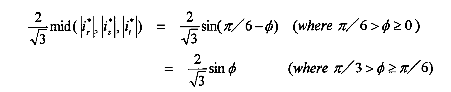

- The matrix converter as claimed in Claim 1, wherein
the carrier signal is a triangle wave signal having a generally constant amplitude. - The matrix converter as claimed in Claim 1, wherein
the carrier signal is a sawtooth wave signal having a generally constant amplitude. - The matrix converter as claimed in Claim 4, further comprising
a holding section (14, 16) for holding the output voltage command signal corrected by the signal correcting section (13) and power supply voltage information, wherein
the holding section (14, 16) updates the output voltage command signal and the power supply voltage information at a timing of a peak of the carrier signal, and
the PWM conversion signal generating section (15, 17) generates the PWM conversion signal based on the output voltage command signal and the power supply voltage information held by the holding section (14, 16). - A matrix converter control method for converting a three-phase ac input voltage into a specified three-phase ac output voltage, comprising the steps of:generating an output voltage command signal for outputting the specified three-phase ac output voltage by an output voltage command signal generating section (11);generating a signal representing a current flow ratio by a current flow ratio generating section (12) based on a specified input current command signal;correcting, by a signal correcting section (13), the output voltage command signal generated by the output voltage command signal generating section (11) based on the output voltage command signal and the signal representing the current flow ratio generated by the current flow ratio generating section (12);generating a PWM conversion signal by a PWM conversion signal generating section (15, 17) based on the output voltage command signal corrected by the signal correcting section (13) and a carrier signal; andconverting the three-phase ac input voltage into the specified three-phase ac output voltage by a conversion section (1) based on the PWM conversion signal generated by the PWM conversion signal generating section (15, 17).
Applications Claiming Priority (2)
| Application Number | Priority Date | Filing Date | Title |
|---|---|---|---|
| JP2006125692A JP4029904B2 (en) | 2006-04-28 | 2006-04-28 | Matrix converter and control method of matrix converter |
| PCT/JP2007/058627 WO2007125828A1 (en) | 2006-04-28 | 2007-04-20 | Matrix converter, and control method for the matrix converter |
Publications (3)
| Publication Number | Publication Date |
|---|---|
| EP2017947A1 true EP2017947A1 (en) | 2009-01-21 |
| EP2017947A4 EP2017947A4 (en) | 2016-08-10 |
| EP2017947B1 EP2017947B1 (en) | 2021-07-14 |
Family
ID=38655354
Family Applications (1)
| Application Number | Title | Priority Date | Filing Date |
|---|---|---|---|
| EP07742062.8A Active EP2017947B1 (en) | 2006-04-28 | 2007-04-20 | Matrix converter, and control method for the matrix converter |
Country Status (8)
| Country | Link |
|---|---|
| US (1) | US7881087B2 (en) |
| EP (1) | EP2017947B1 (en) |
| JP (1) | JP4029904B2 (en) |
| KR (1) | KR101024822B1 (en) |
| CN (1) | CN101432956B (en) |
| AU (1) | AU2007244502B2 (en) |
| BR (1) | BRPI0710957B1 (en) |
| WO (1) | WO2007125828A1 (en) |
Cited By (9)
| Publication number | Priority date | Publication date | Assignee | Title |
|---|---|---|---|---|
| RU2414800C1 (en) * | 2010-03-19 | 2011-03-20 | Государственное образовательное учреждение высшего профессионального образования "Ульяновский государственный технический университет" | Method of scalar control of (3×3)-phase matrix frequency converter |
| EP2822167A3 (en) * | 2013-06-28 | 2015-09-30 | Kabushiki Kaisha Yaskawa Denki | Control of a matrix converter in the saturation area of the output voltages |
| EP2755311A4 (en) * | 2011-09-06 | 2015-10-07 | Nissan Motor | POWER CONVERSION DEVICE |
| EP2755313A4 (en) * | 2011-09-06 | 2015-10-07 | Nissan Motor | POWER CONVERSION DEVICE |
| EP2755312A4 (en) * | 2011-09-06 | 2015-10-07 | Nissan Motor | POWER CONVERSION DEVICE |
| EP2950437A4 (en) * | 2013-01-23 | 2016-12-14 | Fujitsu General Ltd | MATRIX CONVERTER |
| EP3011665A4 (en) * | 2013-06-20 | 2017-04-26 | Kraftpowercon India Private Limited | Ac/ac converter for conversion between three phase and single phase power supplies |
| RU2641653C1 (en) * | 2016-09-26 | 2018-01-19 | федеральное государственное бюджетное образовательное учреждение высшего образования "Нижегородский государственный технический университет им. Р.Е. Алексеева" (НГТУ) | Control method for frequency matrix converter |
| EP3261247B1 (en) * | 2015-02-16 | 2022-07-06 | Mitsubishi Electric Corporation | Power conversion device |
Families Citing this family (18)
| Publication number | Priority date | Publication date | Assignee | Title |
|---|---|---|---|---|
| JP4957303B2 (en) * | 2007-03-14 | 2012-06-20 | 株式会社明電舎 | Space vector modulation method for AC-AC direct conversion device |
| WO2009013992A1 (en) * | 2007-07-20 | 2009-01-29 | Kabushiki Kaisha Yaskawa Denki | Matrix converter |
| JP5171286B2 (en) * | 2008-01-24 | 2013-03-27 | 東洋電機製造株式会社 | Matrix converter controller |
| WO2010029808A1 (en) * | 2008-09-11 | 2010-03-18 | 株式会社ダイヘン | Inverter control circuit and interconnection inverter system having that inverter control circuit |
| WO2012005604A2 (en) * | 2010-06-29 | 2012-01-12 | Eaton Industries Company | Power factor control of a cyclo-converter |
| CN102035216B (en) * | 2010-12-15 | 2013-01-23 | 南京航空航天大学 | Grid-connected control method and device for combining generator and matrix converter |
| CN103066910B (en) * | 2012-12-19 | 2015-04-15 | 天津大学 | Direct torque control method capable of hindering torque impulse |
| US20150280595A1 (en) * | 2014-04-01 | 2015-10-01 | Hamilton Sundstrand Corporation | Switch configuration for a matrix convertor |
| JP2015201996A (en) * | 2014-04-09 | 2015-11-12 | 株式会社安川電機 | Power conversion device, control device for power conversion device, and control method for power conversion device |
| CN106471725B (en) * | 2014-07-18 | 2018-02-27 | 大金工业株式会社 | Direct Type AC Power Converter |
| JP6079808B2 (en) * | 2015-03-27 | 2017-02-15 | 株式会社富士通ゼネラル | 3-phase / single-phase matrix converter |
| US10177572B2 (en) * | 2015-03-31 | 2019-01-08 | Fujitsu General Limited | DC/AC system interconnection device and AC/AC system interconnection device |
| RU2018130979A (en) | 2016-03-11 | 2020-04-13 | АйТиТи МЭНЬЮФЭКЧУРИНГ ЭНТЕРПРАЙЗИС ЭлЭлСи | An electric motor assembly for driving a pump or rotary device having a bearing plane with a multilayer power and control circuit board assembly |
| US11394264B2 (en) | 2020-01-21 | 2022-07-19 | Itt Manufacturing Enterprises Llc | Motor assembly for driving a pump or rotary device with a low inductance resistor for a matrix converter |
| US11451156B2 (en) | 2020-01-21 | 2022-09-20 | Itt Manufacturing Enterprises Llc | Overvoltage clamp for a matrix converter |
| US11448225B2 (en) | 2020-01-21 | 2022-09-20 | Itt Manufacturing Enterprises Llc | Motor assembly for driving a pump or rotary device having a cooling duct |
| CN113794369B (en) * | 2021-09-17 | 2024-06-11 | 北京迪赛奇正科技有限公司 | Three-phase PFC and PWM modulation method based on BUCK circuit |
| WO2025184646A1 (en) * | 2024-03-01 | 2025-09-04 | Borgwarner Inc. | Carrier-based modulation methods for a matrix converter |
Family Cites Families (10)
| Publication number | Priority date | Publication date | Assignee | Title |
|---|---|---|---|---|
| US4648022A (en) * | 1986-02-14 | 1987-03-03 | Westinghouse Electric Corp. | Matrix converter control system |
| JP3815529B2 (en) * | 1998-05-27 | 2006-08-30 | 株式会社安川電機 | Control device for three-phase / three-phase PWM cycloconverter |
| JP3509094B2 (en) * | 1999-04-13 | 2004-03-22 | 株式会社安川電機 | Control device for three-phase / single-phase PWM cycloconverter |
| USRE38439E1 (en) * | 1999-05-12 | 2004-02-24 | Otis Elevator Company | Control of a DC matrix converter |
| TW533667B (en) * | 2000-08-31 | 2003-05-21 | Univ Illinois | Multiple output dynamically regulated charge pump power converter |
| DE10057783A1 (en) * | 2000-11-22 | 2002-06-06 | Siemens Ag | Method for controlling a matrix converter |
| US6995992B2 (en) * | 2003-06-20 | 2006-02-07 | Wisconsin Alumni Research Foundation | Dual bridge matrix converter |
| DE112006000887T5 (en) * | 2005-04-15 | 2008-03-06 | Kabushiki Kaisha Yaskawa Denki, Kitakyushu | Device for converting a matrix |
| JP2007082321A (en) * | 2005-09-14 | 2007-03-29 | Fuji Electric Fa Components & Systems Co Ltd | Electric motor drive |
| CN103051203B (en) * | 2006-04-20 | 2015-11-04 | 大金工业株式会社 | The control method of power inverter and power inverter |
-
2006
- 2006-04-28 JP JP2006125692A patent/JP4029904B2/en not_active Expired - Fee Related
-
2007
- 2007-04-20 BR BRPI0710957A patent/BRPI0710957B1/en not_active IP Right Cessation
- 2007-04-20 CN CN2007800151616A patent/CN101432956B/en active Active
- 2007-04-20 US US12/298,597 patent/US7881087B2/en active Active
- 2007-04-20 AU AU2007244502A patent/AU2007244502B2/en not_active Ceased
- 2007-04-20 WO PCT/JP2007/058627 patent/WO2007125828A1/en not_active Ceased
- 2007-04-20 EP EP07742062.8A patent/EP2017947B1/en active Active
- 2007-04-20 KR KR1020087024956A patent/KR101024822B1/en not_active Expired - Fee Related
Non-Patent Citations (1)
| Title |
|---|
| See references of WO2007125828A1 * |
Cited By (11)
| Publication number | Priority date | Publication date | Assignee | Title |
|---|---|---|---|---|
| RU2414800C1 (en) * | 2010-03-19 | 2011-03-20 | Государственное образовательное учреждение высшего профессионального образования "Ульяновский государственный технический университет" | Method of scalar control of (3×3)-phase matrix frequency converter |
| EP2755311A4 (en) * | 2011-09-06 | 2015-10-07 | Nissan Motor | POWER CONVERSION DEVICE |
| EP2755313A4 (en) * | 2011-09-06 | 2015-10-07 | Nissan Motor | POWER CONVERSION DEVICE |
| EP2755312A4 (en) * | 2011-09-06 | 2015-10-07 | Nissan Motor | POWER CONVERSION DEVICE |
| EP2950437A4 (en) * | 2013-01-23 | 2016-12-14 | Fujitsu General Ltd | MATRIX CONVERTER |
| US9979311B2 (en) | 2013-01-23 | 2018-05-22 | Fujitsu General Limited | Matrix converter |
| EP3011665A4 (en) * | 2013-06-20 | 2017-04-26 | Kraftpowercon India Private Limited | Ac/ac converter for conversion between three phase and single phase power supplies |
| EP2822167A3 (en) * | 2013-06-28 | 2015-09-30 | Kabushiki Kaisha Yaskawa Denki | Control of a matrix converter in the saturation area of the output voltages |
| US9219424B2 (en) | 2013-06-28 | 2015-12-22 | Kabushiki Kaisha Yaskawa Denki | Matrix converter |
| EP3261247B1 (en) * | 2015-02-16 | 2022-07-06 | Mitsubishi Electric Corporation | Power conversion device |
| RU2641653C1 (en) * | 2016-09-26 | 2018-01-19 | федеральное государственное бюджетное образовательное учреждение высшего образования "Нижегородский государственный технический университет им. Р.Е. Алексеева" (НГТУ) | Control method for frequency matrix converter |
Also Published As
| Publication number | Publication date |
|---|---|
| CN101432956B (en) | 2011-04-06 |
| KR101024822B1 (en) | 2011-03-31 |
| US7881087B2 (en) | 2011-02-01 |
| US20090257261A1 (en) | 2009-10-15 |
| WO2007125828A1 (en) | 2007-11-08 |
| BRPI0710957B1 (en) | 2018-09-18 |
| EP2017947B1 (en) | 2021-07-14 |
| KR20090004955A (en) | 2009-01-12 |
| AU2007244502A1 (en) | 2007-11-08 |
| BRPI0710957A2 (en) | 2012-02-14 |
| CN101432956A (en) | 2009-05-13 |
| AU2007244502B2 (en) | 2010-05-13 |
| EP2017947A4 (en) | 2016-08-10 |
| JP4029904B2 (en) | 2008-01-09 |
| JP2007300719A (en) | 2007-11-15 |
Similar Documents
| Publication | Publication Date | Title |
|---|---|---|
| EP2017947B1 (en) | Matrix converter, and control method for the matrix converter | |
| KR100982119B1 (en) | Power converter and control method of the power converter | |
| US10630163B2 (en) | Pulse width modulation method, pulse width modulation system, and controller | |
| US8446742B2 (en) | Inverter control circuit and interconnection inverter system having that inverter control circuit | |
| EP3896835B1 (en) | Power conversion device | |
| KR20020079966A (en) | PWM Pulse Control Method | |
| KR20160122378A (en) | Apparatus for controlling grid-connected inverter | |
| EP1741178B1 (en) | Power converter apparatus and methods using a phase reference derived from a dc bus voltage | |
| RU2379819C2 (en) | Method to control three-phase bridge converter | |
| JP4135027B2 (en) | Power converter and control method of power converter | |
| US20020121875A1 (en) | Method and apparatus for pulse width modulation | |
| JPH07177753A (en) | Power converter control method and device | |
| JP3182322B2 (en) | PWM control device for NPC inverter | |
| JP2002186251A (en) | Power converter control device | |
| JP5251344B2 (en) | Control device for two-phase AC rotating machine | |
| JP3171505B2 (en) | PWM inverter control device | |
| JPS6115670B2 (en) | ||
| KR100319551B1 (en) | Control apparatus of NPC inverter using hysteresis current controller | |
| JP3222794B2 (en) | Power converter | |
| JP2007318994A (en) | Power converter | |
| JPS59165982A (en) | Vector control system of induction motor |
Legal Events
| Date | Code | Title | Description |
|---|---|---|---|
| PUAI | Public reference made under article 153(3) epc to a published international application that has entered the european phase |
Free format text: ORIGINAL CODE: 0009012 |
|
| 17P | Request for examination filed |
Effective date: 20081106 |
|
| AK | Designated contracting states |
Kind code of ref document: A1 Designated state(s): AT BE BG CH CY CZ DE DK EE ES FI FR GB GR HU IE IS IT LI LT LU LV MC MT NL PL PT RO SE SI SK TR |
|
| AX | Request for extension of the european patent |
Extension state: AL BA HR MK RS |
|
| DAX | Request for extension of the european patent (deleted) | ||
| RA4 | Supplementary search report drawn up and despatched (corrected) |
Effective date: 20160712 |
|
| RIC1 | Information provided on ipc code assigned before grant |
Ipc: H02M 5/293 20060101AFI20160706BHEP Ipc: H02M 5/275 20060101ALI20160706BHEP Ipc: H02M 5/297 20060101ALI20160706BHEP |
|
| RIC1 | Information provided on ipc code assigned before grant |
Ipc: H02M 5/293 20060101AFI20200817BHEP Ipc: H02M 5/275 20060101ALI20200817BHEP Ipc: H02M 5/297 20060101ALI20200817BHEP |
|
| GRAP | Despatch of communication of intention to grant a patent |
Free format text: ORIGINAL CODE: EPIDOSNIGR1 |
|
| STAA | Information on the status of an ep patent application or granted ep patent |
Free format text: STATUS: GRANT OF PATENT IS INTENDED |
|
| INTG | Intention to grant announced |
Effective date: 20201002 |
|
| GRAJ | Information related to disapproval of communication of intention to grant by the applicant or resumption of examination proceedings by the epo deleted |
Free format text: ORIGINAL CODE: EPIDOSDIGR1 |
|
| STAA | Information on the status of an ep patent application or granted ep patent |
Free format text: STATUS: REQUEST FOR EXAMINATION WAS MADE |
|
| INTC | Intention to grant announced (deleted) | ||
| GRAP | Despatch of communication of intention to grant a patent |
Free format text: ORIGINAL CODE: EPIDOSNIGR1 |
|
| STAA | Information on the status of an ep patent application or granted ep patent |
Free format text: STATUS: GRANT OF PATENT IS INTENDED |
|
| INTG | Intention to grant announced |
Effective date: 20210319 |
|
| GRAS | Grant fee paid |
Free format text: ORIGINAL CODE: EPIDOSNIGR3 |
|
| GRAA | (expected) grant |
Free format text: ORIGINAL CODE: 0009210 |
|
| STAA | Information on the status of an ep patent application or granted ep patent |
Free format text: STATUS: THE PATENT HAS BEEN GRANTED |
|
| AK | Designated contracting states |
Kind code of ref document: B1 Designated state(s): AT BE BG CH CY CZ DE DK EE ES FI FR GB GR HU IE IS IT LI LT LU LV MC MT NL PL PT RO SE SI SK TR |
|
| REG | Reference to a national code |
Ref country code: GB Ref legal event code: FG4D |
|
| REG | Reference to a national code |
Ref country code: IE Ref legal event code: FG4D |
|
| REG | Reference to a national code |
Ref country code: DE Ref legal event code: R096 Ref document number: 602007061224 Country of ref document: DE |
|
| REG | Reference to a national code |
Ref country code: AT Ref legal event code: REF Ref document number: 1411429 Country of ref document: AT Kind code of ref document: T Effective date: 20210815 |
|
| REG | Reference to a national code |
Ref country code: LT Ref legal event code: MG9D |
|
| REG | Reference to a national code |
Ref country code: NL Ref legal event code: MP Effective date: 20210714 |
|
| REG | Reference to a national code |
Ref country code: AT Ref legal event code: MK05 Ref document number: 1411429 Country of ref document: AT Kind code of ref document: T Effective date: 20210714 |
|
| PG25 | Lapsed in a contracting state [announced via postgrant information from national office to epo] |
Ref country code: LT Free format text: LAPSE BECAUSE OF FAILURE TO SUBMIT A TRANSLATION OF THE DESCRIPTION OR TO PAY THE FEE WITHIN THE PRESCRIBED TIME-LIMIT Effective date: 20210714 Ref country code: AT Free format text: LAPSE BECAUSE OF FAILURE TO SUBMIT A TRANSLATION OF THE DESCRIPTION OR TO PAY THE FEE WITHIN THE PRESCRIBED TIME-LIMIT Effective date: 20210714 Ref country code: BG Free format text: LAPSE BECAUSE OF FAILURE TO SUBMIT A TRANSLATION OF THE DESCRIPTION OR TO PAY THE FEE WITHIN THE PRESCRIBED TIME-LIMIT Effective date: 20211014 Ref country code: ES Free format text: LAPSE BECAUSE OF FAILURE TO SUBMIT A TRANSLATION OF THE DESCRIPTION OR TO PAY THE FEE WITHIN THE PRESCRIBED TIME-LIMIT Effective date: 20210714 Ref country code: FI Free format text: LAPSE BECAUSE OF FAILURE TO SUBMIT A TRANSLATION OF THE DESCRIPTION OR TO PAY THE FEE WITHIN THE PRESCRIBED TIME-LIMIT Effective date: 20210714 Ref country code: PT Free format text: LAPSE BECAUSE OF FAILURE TO SUBMIT A TRANSLATION OF THE DESCRIPTION OR TO PAY THE FEE WITHIN THE PRESCRIBED TIME-LIMIT Effective date: 20211115 Ref country code: NL Free format text: LAPSE BECAUSE OF FAILURE TO SUBMIT A TRANSLATION OF THE DESCRIPTION OR TO PAY THE FEE WITHIN THE PRESCRIBED TIME-LIMIT Effective date: 20210714 Ref country code: SE Free format text: LAPSE BECAUSE OF FAILURE TO SUBMIT A TRANSLATION OF THE DESCRIPTION OR TO PAY THE FEE WITHIN THE PRESCRIBED TIME-LIMIT Effective date: 20210714 |
|
| PG25 | Lapsed in a contracting state [announced via postgrant information from national office to epo] |
Ref country code: PL Free format text: LAPSE BECAUSE OF FAILURE TO SUBMIT A TRANSLATION OF THE DESCRIPTION OR TO PAY THE FEE WITHIN THE PRESCRIBED TIME-LIMIT Effective date: 20210714 Ref country code: LV Free format text: LAPSE BECAUSE OF FAILURE TO SUBMIT A TRANSLATION OF THE DESCRIPTION OR TO PAY THE FEE WITHIN THE PRESCRIBED TIME-LIMIT Effective date: 20210714 Ref country code: GR Free format text: LAPSE BECAUSE OF FAILURE TO SUBMIT A TRANSLATION OF THE DESCRIPTION OR TO PAY THE FEE WITHIN THE PRESCRIBED TIME-LIMIT Effective date: 20211015 |
|
| REG | Reference to a national code |
Ref country code: DE Ref legal event code: R097 Ref document number: 602007061224 Country of ref document: DE |
|
| PG25 | Lapsed in a contracting state [announced via postgrant information from national office to epo] |
Ref country code: DK Free format text: LAPSE BECAUSE OF FAILURE TO SUBMIT A TRANSLATION OF THE DESCRIPTION OR TO PAY THE FEE WITHIN THE PRESCRIBED TIME-LIMIT Effective date: 20210714 |
|
| PLBE | No opposition filed within time limit |
Free format text: ORIGINAL CODE: 0009261 |
|
| STAA | Information on the status of an ep patent application or granted ep patent |
Free format text: STATUS: NO OPPOSITION FILED WITHIN TIME LIMIT |
|
| PG25 | Lapsed in a contracting state [announced via postgrant information from national office to epo] |
Ref country code: SK Free format text: LAPSE BECAUSE OF FAILURE TO SUBMIT A TRANSLATION OF THE DESCRIPTION OR TO PAY THE FEE WITHIN THE PRESCRIBED TIME-LIMIT Effective date: 20210714 Ref country code: RO Free format text: LAPSE BECAUSE OF FAILURE TO SUBMIT A TRANSLATION OF THE DESCRIPTION OR TO PAY THE FEE WITHIN THE PRESCRIBED TIME-LIMIT Effective date: 20210714 Ref country code: EE Free format text: LAPSE BECAUSE OF FAILURE TO SUBMIT A TRANSLATION OF THE DESCRIPTION OR TO PAY THE FEE WITHIN THE PRESCRIBED TIME-LIMIT Effective date: 20210714 Ref country code: CZ Free format text: LAPSE BECAUSE OF FAILURE TO SUBMIT A TRANSLATION OF THE DESCRIPTION OR TO PAY THE FEE WITHIN THE PRESCRIBED TIME-LIMIT Effective date: 20210714 |
|
| 26N | No opposition filed |
Effective date: 20220419 |
|
| PG25 | Lapsed in a contracting state [announced via postgrant information from national office to epo] |
Ref country code: IT Free format text: LAPSE BECAUSE OF FAILURE TO SUBMIT A TRANSLATION OF THE DESCRIPTION OR TO PAY THE FEE WITHIN THE PRESCRIBED TIME-LIMIT Effective date: 20210714 |
|
| REG | Reference to a national code |
Ref country code: CH Ref legal event code: PL |
|
| REG | Reference to a national code |
Ref country code: BE Ref legal event code: MM Effective date: 20220430 |
|
| PG25 | Lapsed in a contracting state [announced via postgrant information from national office to epo] |
Ref country code: MC Free format text: LAPSE BECAUSE OF FAILURE TO SUBMIT A TRANSLATION OF THE DESCRIPTION OR TO PAY THE FEE WITHIN THE PRESCRIBED TIME-LIMIT Effective date: 20210714 Ref country code: LU Free format text: LAPSE BECAUSE OF NON-PAYMENT OF DUE FEES Effective date: 20220420 Ref country code: LI Free format text: LAPSE BECAUSE OF NON-PAYMENT OF DUE FEES Effective date: 20220430 Ref country code: CH Free format text: LAPSE BECAUSE OF NON-PAYMENT OF DUE FEES Effective date: 20220430 |
|
| PG25 | Lapsed in a contracting state [announced via postgrant information from national office to epo] |
Ref country code: BE Free format text: LAPSE BECAUSE OF NON-PAYMENT OF DUE FEES Effective date: 20220430 |
|
| PG25 | Lapsed in a contracting state [announced via postgrant information from national office to epo] |
Ref country code: IE Free format text: LAPSE BECAUSE OF NON-PAYMENT OF DUE FEES Effective date: 20220420 |
|
| P01 | Opt-out of the competence of the unified patent court (upc) registered |
Effective date: 20230525 |
|
| PG25 | Lapsed in a contracting state [announced via postgrant information from national office to epo] |
Ref country code: HU Free format text: LAPSE BECAUSE OF FAILURE TO SUBMIT A TRANSLATION OF THE DESCRIPTION OR TO PAY THE FEE WITHIN THE PRESCRIBED TIME-LIMIT; INVALID AB INITIO Effective date: 20070420 |
|
| PG25 | Lapsed in a contracting state [announced via postgrant information from national office to epo] |
Ref country code: CY Free format text: LAPSE BECAUSE OF FAILURE TO SUBMIT A TRANSLATION OF THE DESCRIPTION OR TO PAY THE FEE WITHIN THE PRESCRIBED TIME-LIMIT Effective date: 20210714 |
|
| PG25 | Lapsed in a contracting state [announced via postgrant information from national office to epo] |
Ref country code: MT Free format text: LAPSE BECAUSE OF FAILURE TO SUBMIT A TRANSLATION OF THE DESCRIPTION OR TO PAY THE FEE WITHIN THE PRESCRIBED TIME-LIMIT Effective date: 20210714 |
|
| PGFP | Annual fee paid to national office [announced via postgrant information from national office to epo] |
Ref country code: DE Payment date: 20250305 Year of fee payment: 19 |
|
| PG25 | Lapsed in a contracting state [announced via postgrant information from national office to epo] |
Ref country code: TR Free format text: LAPSE BECAUSE OF FAILURE TO SUBMIT A TRANSLATION OF THE DESCRIPTION OR TO PAY THE FEE WITHIN THE PRESCRIBED TIME-LIMIT Effective date: 20210714 |
|
| PGFP | Annual fee paid to national office [announced via postgrant information from national office to epo] |
Ref country code: GB Payment date: 20260313 Year of fee payment: 20 |
|
| PGFP | Annual fee paid to national office [announced via postgrant information from national office to epo] |
Ref country code: FR Payment date: 20260309 Year of fee payment: 20 |