EP2017773B1 - Verfahren und Vorrichtung zur Positionsbestimmung eines auf einer Transportvorrichtung positionierten Produktionsteils - Google Patents
Verfahren und Vorrichtung zur Positionsbestimmung eines auf einer Transportvorrichtung positionierten Produktionsteils Download PDFInfo
- Publication number
- EP2017773B1 EP2017773B1 EP08104495A EP08104495A EP2017773B1 EP 2017773 B1 EP2017773 B1 EP 2017773B1 EP 08104495 A EP08104495 A EP 08104495A EP 08104495 A EP08104495 A EP 08104495A EP 2017773 B1 EP2017773 B1 EP 2017773B1
- Authority
- EP
- European Patent Office
- Prior art keywords
- detection
- read
- unit
- units
- transport device
- Prior art date
- Legal status (The legal status is an assumption and is not a legal conclusion. Google has not performed a legal analysis and makes no representation as to the accuracy of the status listed.)
- Not-in-force
Links
Images

Classifications
-
- G—PHYSICS
- G06—COMPUTING OR CALCULATING; COUNTING
- G06Q—INFORMATION AND COMMUNICATION TECHNOLOGY [ICT] SPECIALLY ADAPTED FOR ADMINISTRATIVE, COMMERCIAL, FINANCIAL, MANAGERIAL OR SUPERVISORY PURPOSES; SYSTEMS OR METHODS SPECIALLY ADAPTED FOR ADMINISTRATIVE, COMMERCIAL, FINANCIAL, MANAGERIAL OR SUPERVISORY PURPOSES, NOT OTHERWISE PROVIDED FOR
- G06Q10/00—Administration; Management
- G06Q10/08—Logistics, e.g. warehousing, loading or distribution; Inventory or stock management
Definitions
- the invention relates to a method and a device for determining the position of production parts positioned on a transport device, wherein each production part carries a non-contact readable storage unit in which a part identifier identifying the production part is stored.
- Such a method or such a device is used in particular for manufacturing processes for tracking and tracing and for improving the quality of products.
- the production parts in a transport device (support frame, eg a skid) are at least partially guided through the production line.
- the respective position of the production parts in the carrier frame can influence the quality of the products.
- the upper parts will have a different quality than the underlying parts (paint mist distribution, etc.).
- a further possible application is given, for example, in processes in which the temperature distribution during the passage of the production parts has quality-relevant influences on the production process in temperature-dependent process stages, the temperature distribution depending on the local position of the production parts in the transport device (above higher temperature than above, etc.).
- reactive SPC Statistical Process Control
- the invention has for its object to automatically locate production parts on a transport device.
- a response signal is repeatedly emitted to the memory units of the production parts, which upon receipt triggers a corresponding response signal. If, in turn, a detection unit receives the response signal of a memory unit, then the readout attempt of this memory unit was successful for the relevant detection unit.
- Each acquisition unit is assigned the (total) number of successful read attempts for each storage unit. Since the success of a readout attempt depends on the distance of the detection unit receiving the detection unit from the respective memory unit, can be closed by means of a computer unit on the frequency distribution of the successful Auslese Moie on the position of the respective storage unit - and thus of course the relevant production part - on the transport device.
- a transport device has a defined and known number of possible positions for production parts.
- a transport device with, for example, three positions (top, middle, bottom) would theoretically meet a detection system with two superimposed detection units.
- the upper detection unit would only be able to read out the storage units from the upper two positions and the lower detection unit could only read from the lower two positions. Ie at only the upper detection unit would address the upper memory unit, both detection units in the middle memory unit and only the lower detection unit in the lower memory unit.
- the detection units can each have a reader on each side, so that here two detection systems are used, which are connected to a computer unit for evaluating the frequency distributions of the successful Auslese Listee.
- Each production part (or product) is equipped with a unique part identifier (transponder ID).
- a unique part identifier (transponder ID).
- an assignment of the local placement on the transport device (support frame) takes place.
- the technical reading units i.e., the detecting units, e.g., antennas
- the specific scanning method the frequency of the received transponder information can be evaluated. From the frequency in combination with the respective receiving position of the antennas, the local position can be determined both horizontally and vertically. The result is an assignment of the transponder ID to local positions on the support frame (left, right and top, center, bottom).
- the inventive solution thus the production parts in the transport device - the support frame, eg Skid - automatically and contactlessly located.
- This not only allows tracking and tracing of products in the manufacturing process, but in particular has the advantage that it is possible with the described method to automatically determine the local position exactly to draw in process specifics conclusions on a dependency of Specificity of the position of the production parts to be able to provide (eg paint mist distribution, temperature distribution, etc.).
- the readout attempt is considered successful for a detection unit when it sends the response signal and at least one detection unit receives the response signal, the success of a readout attempt being dependent on a distance of the detection unit transmitting the response signal to the memory unit to be read.
- the storage units can receive the response signal only when they are in proximity to the detection unit transmitting the response signal, so that a response signal received from any detection unit includes the information that the memory unit concerned was close to the detection unit transmitting the response signal. Thus, this information can also be evaluated as a successful readout attempt for the transmitting registration unit and used for the evaluation.
- At least one detection unit is operated in a transmission state for transmitting the response signal and then in a reception state for receiving the response signal, or vice versa.
- the respective transmission and reception function can be changed as a rolling method, whereby this detection unit can also itself receive the response signal of the memory unit to be read out on the response signal emitted by it.
- At least one detection unit changes from the reception state to the transmission state or vice versa.
- This will be another operating condition provided, whereby the at least one detection system can be operated flexibly.
- one detection unit first sends the response signal while the other detection units are in the receiving state.
- another detection unit can then change to the transmission state, while the detection unit first transmitting the response signal changes to the reception state.
- the respective number of successful readout attempts is stored in a data structure in a data memory of the computer unit.
- the data structure e.g. may be formed as a matrix, in the usually already existing data storage of the computer unit can be dispensed with the establishment of memories in the detection units or in the reader.
- a transport speed with which the transport device is moved in a transport direction through the total capture area is determined as a function of the extent of the total capture area in the transport direction and on the number of successful readout attempts. For a reasonable statistical evaluation, a minimum number of readout attempts is required.
- the transport speed of the transport device in the transport direction through the total registration area must not be so fast that this minimum number can no longer be achieved.
- the required minimum number is not fixed, but depends on the arrangement, number and sensitivity of the detection units, and is therefore possibly to be determined for each case by test runs. However, it is advisable for a reliable determination of the positions of the production parts on the transport device anyway, to move in the number of successful Auslese Moie significantly above the required minimum number.
- At least one detection unit is arranged in a holding means.
- This allows a flexible arrangement of the detection units, in particular in the vertical direction.
- these are fastened to two holding means formed as masts at different heights.
- the detection units are arranged such that at least two of the detection areas overlap at least partially. In this way, depending on the position of the possible positions of the production parts on the transport device relative to the detection units used, the statistical evaluation of the frequency distribution and thus the localization of the production parts can be improved if, for example, a memory unit is guided through the total detection area at a height between two detection units ,
- the number of detection units is selected to be greater than the number of possible positions to be determined on the transport device.
- a summation of the numbers of successful readout attempts of respectively adjacent detection units is carried out with respect to each memory unit and closed on the transport device from the largest sum to the position of the production part assigned to the respective storage unit.
- RFID chips are used as storage units. These are meanwhile widely used and thus represent a cost effective solution for implementing the method according to the invention.
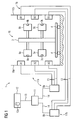
- Fig. 1 shows a device for determining the position 1 of production parts 5a, 5b, 6a, 6b on a transport device 3, the four possible positions for the production parts 5a, 5b, 6a, 6b has (left and right respectively top and bottom).
- a part identifier (or transponder ID) uniquely identifying the production parts 5a, 5b, 6a, 6b is stored in a respective storage unit 7a, 7b, 8a, 8b which is attached to each production part 5a, 5b, 6a, 6b.
- two detection systems 17a, 17b are provided which each consist of a reading device 9a, 9b and in each case three detection units A1, A2, A3, B1, B2, B3 connected to the reading devices 9a, 9b via, for example, antenna lines 13.
- the detection units A1, A2, A3, B1, B2, B3 each have a detection range Ea1, Ea2, Ea3, Eb1, Eb2, Eb3 (see FIG. FIGS. 2 and 3 ), which together form an overall detection area 16, by means of which the transport device 3 can be moved onto, for example, transport rollers 4.
- the detection units A1, A2, A3, B1, B2, B3 are each detection system 17a, 17b arranged on a holding means 10a, 10b, wherein the transport device 3 can be guided between the holding means 10a, 10b.
- the transport speed in the transport direction through the total detection area 16 is typically between 0.1 m / s and 2 m / s, but in individual cases may of course deviate from these values.
- the detection units A1, A2, A3, B1, B2, B3 are advantageously in each case in a transmission state for transmitting a response signal for the memory units 7a, 7b, 8a, 8b and in a reception state for receiving the response signal containing the part identifier of the memory units 7a, 7b, 8a, 8b so that, in a rolling process, each detection unit A1, A2, A3, B1, B2, B3 can receive the response signal following the response signal sent by itself.
- each detection unit A1, A2, A3, B1, B2, B3 now performs several readout attempts, each detection unit A1, A2, A3, B1, B2, B3 for each memory unit 7a, 7b, 8a, 8b, the number n11, ..., n46 of the successful Auslese Mele is assigned.
- the readers 9a, 9b are connected, for example, by means of an Ethernet switch 11 via Ethernet lines 14, 15 to a computer unit 12 which has a data memory 12a in which the numbers n11,..., N46 of the successful readout attempts are stored in a data structure.
- the computer unit 12 On the basis of these data n11,..., N46, the computer unit 12 now uses a frequency distribution to infer the positions of the production part 5a, 5b, 6a, 6b carrying the respective storage unit 7a, 7b, 8a, 8b on the transport device 3.
- the memory unit 8a is at least mainly detected by the detection units A1 and A2, the memory unit 7a is read at least mainly from the detection units A2 and A3, while for the memory units 7b, 8b and the detection units B1, B2, B3 of the detection system 17b the same applies analogously.
- a summation of the numbers n11, ... , N46 successful Auslese issued each adjacent detection units A1, A2, A3, B1, B2, B3 perform and close from the largest sum on the position of the respective production part 5a, 5b, 6a, 6b.
- the positions of the production parts 5a, 5b, 6a, 6b on the transporting device 3 when carrying the transporting device 3 are automatically determined by the total capturing area 16 of the position determining device 1, thereby not only tracking and / or tracing the production parts 5a, 5b , 6a, 6b is possible, but in particular a contribution to quality improvement through the use of eg reactive SPC (Statistical Process Control) method, which allow for process deviations immediate corrections (readjustments) is made in quality-related influences of the local situation of the production parts 5a, 5b, 6a, 6b on the transport device 3.
- SPC Statistical Process Control
- FIG. 11 shows the detection areas Ea1, Ea2, Ea3, Eb1, Eb2, Eb3 of the detection units A1, A2, A3, B1, B2, B3 Fig. 1 in a side view.
- the detection areas Ea1, Ea2, Ea3, Eb1, Eb2, Eb3 have a funnel-shaped spatial extent with an opening angle which is determined or adjustable by the detection unit A1, A2, A3, B1, B2, B3 and in the example shown in the figure Is 60 °, ie from the bisecting line drawn across the detection units A1, A2, A3, B1, B2, B3 each 30 ° up and down, wherein also detection areas Ea1, Ea2, Ea3, Eb1, Eb2, Eb3 with asymmetric angular distribution are conceivable relative to the transverse line drawn.
- the funnel-shaped detection areas Ea1, Ea2, Ea3, Eb1, Eb2, Eb3 are one shown finite extent, ie they end in the figure at the dot-dash line in the middle between the detection units A1, A2, A3, B1, B2, B3.
- All detection areas Ea1, Ea2, Ea3, Eb1, Eb2, Eb3 together form the total detection area 16, with the two upper and two lower detection areas Ea1, Ea2, Ea3, Eb1, Eb2, Eb3 partially overlapping on the left and right. If now production parts 5a, 5b, 6a, 6b are guided on a transport device 3 through the total detection area 16, wherein the possible positions for the production parts 5a, 5b, 6a, 6b at a height between two detection units A1, A2, A3, B1, B2, B3 are located - as in Fig. 1 shown - so the Auslese brine can also lead to success in each case two detection units A1, A2, A3, B1, B2, B3 to success.
- the evaluation of the frequency distribution of the numbers n11,..., N46 of successful readout attempts can be made simple by summation of respectively adjacent detection units A1, A2, A3, B1, B2, B3 for each memory unit 7a, 7b, 8a, 8b and from this the position of the respective storage unit 7a, 7b, 8a, 8b carrying production part 5a, 5b, 6a, 6b are closed on the transport device 3.
- FIG. 11 shows the detection areas Ea1, Ea2, Ea3, Eb1, Eb2, Eb3 of the detection units A1, A2, A3, B1, B2, B3 Fig. 1 in a plan view, in which case only the respective upper detection areas Ea1, Eb1 and units A1, B1 are shown.
- the same - showing only the respective upper components - also applies to the production parts 6a, 6b including storage units 8a, 8b, which are guided on the transport device 3 in the transport direction 18 through the total detection area 16.
- Shown here is an arrangement in which at a first holding means 10a and a second holding means 10b (not shown) mounted detection units A1, A2, A3 and B1, B2, B3 are not directly opposite, but are mounted parallel to the transport direction 18 shifted ,
- the resulting changed response of the detection units A1, A2, A3, B1, B2, B3 can manifest itself in a changed frequency distribution and thus in a possibly improved localization of the production parts 5a, 5b, 6a, 6b on the transport device 3.
- the same result can also be achieved by arranging the holding means 10a, 10b opposite one another - that is, on a line perpendicular to the "center line" given by the transport direction 18 - but slightly twisting them with opposite directions of rotation.
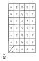
- FIG. 2 shows a data structure for storing the numbers n11,..., n46 of the successful readout attempts, for example in a data memory 12a of a computer unit 12.
- the number n11 for each acquisition unit A1, A2, A3, B1, B2, B3, ..., n46 successful Auslese for each memory unit 7a, 7b, 8a, 8b of a production part 5a, 5b, 6a, 6b filed.
- the number of detection units is 1 - as in Fig. 1 shown - equal to six and the number of positions k of in Fig. 1 with a production part 5a, 5b, 6a, 6b occupied possible positions equal to four.
- the determination of the position of the individual production parts 5a, 5b, 6a, 6b takes place via the determination of the largest sum of successful readout attempts of adjacent detection units A1, A2, A3, B1, B2, B3.
- the production part 5a on the left side (in FIG Fig. 1 ) down because the sum of n12 and n13 is larger than the sum of n11 and n12
- the production part 5b on the lower right side because the sum of n12 and n13 is larger than the sum of n11 and n12
- the invention relates to a method and a device for determining the position of production parts positioned on a transport device, each production part carrying a non-contact readable storage unit in which a part identifier identifying the production part is stored.
- it is proposed to carry out multiple readout attempts of the storage units with at least two detection units during the execution of the transport device through a total detection area formed by the detection units, the success of a readout attempt being dependent on a distance of the detection unit receiving the response signal to be read storage unit, and to close by means of a computer unit on a frequency distribution of the numbers of successful Auslesegrasse on the position of this storage unit carrying production part in the transport device.
Landscapes
- Business, Economics & Management (AREA)
- Engineering & Computer Science (AREA)
- Economics (AREA)
- Tourism & Hospitality (AREA)
- General Business, Economics & Management (AREA)
- Human Resources & Organizations (AREA)
- Marketing (AREA)
- Operations Research (AREA)
- Quality & Reliability (AREA)
- Strategic Management (AREA)
- Development Economics (AREA)
- Physics & Mathematics (AREA)
- Entrepreneurship & Innovation (AREA)
- General Physics & Mathematics (AREA)
- Theoretical Computer Science (AREA)
- Control Of Conveyors (AREA)
- Automatic Assembly (AREA)
- Supply And Installment Of Electrical Components (AREA)
- Testing Electric Properties And Detecting Electric Faults (AREA)
- Control Of Position, Course, Altitude, Or Attitude Of Moving Bodies (AREA)
Priority Applications (1)
| Application Number | Priority Date | Filing Date | Title |
|---|---|---|---|
| PL08104495T PL2017773T3 (pl) | 2007-06-22 | 2008-06-20 | Sposób i urządzenie do ustalania pozycji części produkcyjnych, umieszczonych w urządzeniu transportowym |
Applications Claiming Priority (1)
| Application Number | Priority Date | Filing Date | Title |
|---|---|---|---|
| DE102007029309 | 2007-06-22 |
Publications (2)
| Publication Number | Publication Date |
|---|---|
| EP2017773A1 EP2017773A1 (de) | 2009-01-21 |
| EP2017773B1 true EP2017773B1 (de) | 2009-11-25 |
Family
ID=39773256
Family Applications (1)
| Application Number | Title | Priority Date | Filing Date |
|---|---|---|---|
| EP08104495A Not-in-force EP2017773B1 (de) | 2007-06-22 | 2008-06-20 | Verfahren und Vorrichtung zur Positionsbestimmung eines auf einer Transportvorrichtung positionierten Produktionsteils |
Country Status (8)
| Country | Link |
|---|---|
| EP (1) | EP2017773B1 (pl) |
| AT (1) | ATE450018T1 (pl) |
| DE (1) | DE502008000215D1 (pl) |
| DK (1) | DK2017773T3 (pl) |
| ES (1) | ES2335625T3 (pl) |
| HR (1) | HRP20100075T1 (pl) |
| PL (1) | PL2017773T3 (pl) |
| PT (1) | PT2017773E (pl) |
Family Cites Families (3)
| Publication number | Priority date | Publication date | Assignee | Title |
|---|---|---|---|---|
| DE19854744A1 (de) * | 1998-11-27 | 2000-05-31 | Guth Gordon | System zur Erfassung von Gütern |
| EP1182154A4 (en) * | 2000-01-31 | 2007-12-26 | Ishikawajima Transp Machinery | METHOD AND DEVICE FOR CONTAINER MANAGEMENT |
| US20060152367A1 (en) * | 2004-12-30 | 2006-07-13 | Mr. Karthikeyan Narayanaswamy | System and method to reduce errors, authenticate, and reduce the filling time of medical prescriptions by utilizing RFID tag |
-
2008
- 2008-06-20 DE DE502008000215T patent/DE502008000215D1/de active Active
- 2008-06-20 AT AT08104495T patent/ATE450018T1/de active
- 2008-06-20 ES ES08104495T patent/ES2335625T3/es active Active
- 2008-06-20 PT PT08104495T patent/PT2017773E/pt unknown
- 2008-06-20 EP EP08104495A patent/EP2017773B1/de not_active Not-in-force
- 2008-06-20 PL PL08104495T patent/PL2017773T3/pl unknown
- 2008-06-20 DK DK08104495.0T patent/DK2017773T3/da active
-
2010
- 2010-02-10 HR HR20100075T patent/HRP20100075T1/hr unknown
Also Published As
| Publication number | Publication date |
|---|---|
| EP2017773A1 (de) | 2009-01-21 |
| PT2017773E (pt) | 2010-02-09 |
| PL2017773T3 (pl) | 2010-05-31 |
| DK2017773T3 (da) | 2010-03-29 |
| DE502008000215D1 (de) | 2010-01-07 |
| ES2335625T3 (es) | 2010-03-30 |
| ATE450018T1 (de) | 2009-12-15 |
| HRP20100075T1 (hr) | 2010-03-31 |
Similar Documents
| Publication | Publication Date | Title |
|---|---|---|
| DE60311469T2 (de) | Verfahren und anordnung zur automatischen verifizierung von identitäten von milcherzeugenden tieren | |
| EP3291144B1 (de) | Rfid-vorrichtung und verfahren zur fachbelegungserkennung | |
| EP2087455B1 (de) | Anordnung und verfahren zur datenerfassung | |
| AT514309A2 (de) | System zur Erfassung eines Bestandes an Überwachungsobjekten einer Anlage | |
| DE4437087C2 (de) | Verfahren und Vorrichtungen zum Sortieren von Restaurantgeschirr | |
| DE102007049702A1 (de) | Pickerstrasse | |
| DE102016120386A1 (de) | Verfahren zum Erkennen von Objekten in einem Lager und Flurförderzeug mit einer Einrichtung zum Erkennen von Objekten in einem Lager | |
| EP3836001A1 (de) | Lesen einer vielzahl von codes | |
| EP2887029A1 (de) | Befüllungsvorrichtung und Verfahren zum Erfassen einer Befüllung | |
| EP2479719A2 (de) | System und Verfahren zur Lagerung und Überwachung von Gütern mittels RFID-Technologie | |
| EP2017773B1 (de) | Verfahren und Vorrichtung zur Positionsbestimmung eines auf einer Transportvorrichtung positionierten Produktionsteils | |
| EP2108879B1 (de) | Verfahren und Vorrichtung zur Überwachung eines Durchgangs | |
| DE19732597C2 (de) | Rollwagen mit einem Transponder | |
| DE102016102135B3 (de) | Leiterplatten - Transportsystem und Fertigungssystem | |
| EP2500850B1 (de) | Verfahren und System zur Überwachung von Gegenständen | |
| DE102009008123B4 (de) | Scan-Schleuse | |
| EP4071104A1 (de) | Abfüllen eines mediums | |
| EP3273382B1 (de) | Rfid-lesevorrichtung und verfahren zur fachbelegungserkennung in einem regal | |
| DE19843602A1 (de) | Verfahren und Vorrichtung zum Erfassen der Bewegungen von Prozeßeinheiten während eines Produktionsprozesses in einem vorgegebenen Auswertebereich | |
| EP3323517A1 (de) | Sortiersystem und verfahren zur verfolgung eines einsortierens eines sortierguts in ein sortierregister | |
| DE102009016557B4 (de) | Verfahren zum Zuordnen von mindestens einem kontaktlos auslesbaren Datenträger zu mindestens einem sich räumlich bewegenden Bereich und Vorrichtung zum Ausführen des Verfahrens | |
| WO2006045569A1 (de) | Verfahren und vorrichtung zur überprüfung der beladung einer transportvorrichtung mit gegenständen | |
| AT509024B1 (de) | Verfahren zur bestimmung der ausrichtung eines oberen teils eines stückgutstapels | |
| EP2479720B1 (de) | System und Verfahren zur Lagerung und Überwachung von Gütern mittels RFID-Technologie | |
| EP1762135A1 (de) | System zur Bearbeitung, Pflege und zum Management von Pflanzen |
Legal Events
| Date | Code | Title | Description |
|---|---|---|---|
| PUAI | Public reference made under article 153(3) epc to a published international application that has entered the european phase |
Free format text: ORIGINAL CODE: 0009012 |
|
| AK | Designated contracting states |
Kind code of ref document: A1 Designated state(s): AT BE BG CH CY CZ DE DK EE ES FI FR GB GR HR HU IE IS IT LI LT LU LV MC MT NL NO PL PT RO SE SI SK TR |
|
| AX | Request for extension of the european patent |
Extension state: AL BA MK RS |
|
| 17P | Request for examination filed |
Effective date: 20090105 |
|
| GRAP | Despatch of communication of intention to grant a patent |
Free format text: ORIGINAL CODE: EPIDOSNIGR1 |
|
| GRAS | Grant fee paid |
Free format text: ORIGINAL CODE: EPIDOSNIGR3 |
|
| AKX | Designation fees paid |
Designated state(s): AT BE BG CH CY CZ DE DK EE ES FI FR GB GR HR HU IE IS IT LI LT LU LV MC MT NL NO PL PT RO SE SI SK TR |
|
| GRAA | (expected) grant |
Free format text: ORIGINAL CODE: 0009210 |
|
| AK | Designated contracting states |
Kind code of ref document: B1 Designated state(s): AT BE BG CH CY CZ DE DK EE ES FI FR GB GR HR HU IE IS IT LI LT LU LV MC MT NL NO PL PT RO SE SI SK TR |
|
| REG | Reference to a national code |
Ref country code: GB Ref legal event code: FG4D Free format text: NOT ENGLISH |
|
| REG | Reference to a national code |
Ref country code: CH Ref legal event code: EP |
|
| REG | Reference to a national code |
Ref country code: CH Ref legal event code: NV Representative=s name: SIEMENS SCHWEIZ AG |
|
| REG | Reference to a national code |
Ref country code: IE Ref legal event code: FG4D |
|
| REF | Corresponds to: |
Ref document number: 502008000215 Country of ref document: DE Date of ref document: 20100107 Kind code of ref document: P |
|
| REG | Reference to a national code |
Ref country code: RO Ref legal event code: EPE Ref country code: PT Ref legal event code: SC4A Free format text: AVAILABILITY OF NATIONAL TRANSLATION Effective date: 20100201 |
|
| REG | Reference to a national code |
Ref country code: HR Ref legal event code: TUEP Ref document number: P20100075 Country of ref document: HR |
|
| REG | Reference to a national code |
Ref country code: GR Ref legal event code: EP Ref document number: 20100400358 Country of ref document: GR |
|
| REG | Reference to a national code |
Ref country code: SE Ref legal event code: TRGR |
|
| REG | Reference to a national code |
Ref country code: NL Ref legal event code: T3 |
|
| REG | Reference to a national code |
Ref country code: DK Ref legal event code: T3 |
|
| REG | Reference to a national code |
Ref country code: ES Ref legal event code: FG2A Ref document number: 2335625 Country of ref document: ES Kind code of ref document: T3 |
|
| REG | Reference to a national code |
Ref country code: HR Ref legal event code: T1PR Ref document number: P20100075 Country of ref document: HR |
|
| REG | Reference to a national code |
Ref country code: NO Ref legal event code: T2 Effective date: 20091125 |
|
| LTIE | Lt: invalidation of european patent or patent extension |
Effective date: 20091125 |
|
| PG25 | Lapsed in a contracting state [announced via postgrant information from national office to epo] |
Ref country code: LT Free format text: LAPSE BECAUSE OF FAILURE TO SUBMIT A TRANSLATION OF THE DESCRIPTION OR TO PAY THE FEE WITHIN THE PRESCRIBED TIME-LIMIT Effective date: 20091125 Ref country code: IS Free format text: LAPSE BECAUSE OF FAILURE TO SUBMIT A TRANSLATION OF THE DESCRIPTION OR TO PAY THE FEE WITHIN THE PRESCRIBED TIME-LIMIT Effective date: 20100325 |
|
| REG | Reference to a national code |
Ref country code: SK Ref legal event code: T3 Ref document number: E 6781 Country of ref document: SK |
|
| PG25 | Lapsed in a contracting state [announced via postgrant information from national office to epo] |
Ref country code: SI Free format text: LAPSE BECAUSE OF FAILURE TO SUBMIT A TRANSLATION OF THE DESCRIPTION OR TO PAY THE FEE WITHIN THE PRESCRIBED TIME-LIMIT Effective date: 20091125 Ref country code: LV Free format text: LAPSE BECAUSE OF FAILURE TO SUBMIT A TRANSLATION OF THE DESCRIPTION OR TO PAY THE FEE WITHIN THE PRESCRIBED TIME-LIMIT Effective date: 20091125 Ref country code: CY Free format text: LAPSE BECAUSE OF FAILURE TO SUBMIT A TRANSLATION OF THE DESCRIPTION OR TO PAY THE FEE WITHIN THE PRESCRIBED TIME-LIMIT Effective date: 20091125 |
|
| REG | Reference to a national code |
Ref country code: PL Ref legal event code: T3 |
|
| REG | Reference to a national code |
Ref country code: HU Ref legal event code: AG4A Ref document number: E007326 Country of ref document: HU |
|
| PG25 | Lapsed in a contracting state [announced via postgrant information from national office to epo] |
Ref country code: EE Free format text: LAPSE BECAUSE OF FAILURE TO SUBMIT A TRANSLATION OF THE DESCRIPTION OR TO PAY THE FEE WITHIN THE PRESCRIBED TIME-LIMIT Effective date: 20091125 |
|
| PLBE | No opposition filed within time limit |
Free format text: ORIGINAL CODE: 0009261 |
|
| STAA | Information on the status of an ep patent application or granted ep patent |
Free format text: STATUS: NO OPPOSITION FILED WITHIN TIME LIMIT |
|
| 26N | No opposition filed |
Effective date: 20100826 |
|
| PG25 | Lapsed in a contracting state [announced via postgrant information from national office to epo] |
Ref country code: MC Free format text: LAPSE BECAUSE OF NON-PAYMENT OF DUE FEES Effective date: 20100630 |
|
| PG25 | Lapsed in a contracting state [announced via postgrant information from national office to epo] |
Ref country code: MT Free format text: LAPSE BECAUSE OF FAILURE TO SUBMIT A TRANSLATION OF THE DESCRIPTION OR TO PAY THE FEE WITHIN THE PRESCRIBED TIME-LIMIT Effective date: 20091125 |
|
| REG | Reference to a national code |
Ref country code: HR Ref legal event code: ODRP Ref document number: P20100075 Country of ref document: HR Payment date: 20110617 Year of fee payment: 4 |
|
| PGFP | Annual fee paid to national office [announced via postgrant information from national office to epo] |
Ref country code: HR Payment date: 20110617 Year of fee payment: 4 Ref country code: GR Payment date: 20110621 Year of fee payment: 4 Ref country code: PT Payment date: 20110530 Year of fee payment: 4 Ref country code: IE Payment date: 20110621 Year of fee payment: 4 |
|
| PGFP | Annual fee paid to national office [announced via postgrant information from national office to epo] |
Ref country code: RO Payment date: 20110530 Year of fee payment: 4 Ref country code: SK Payment date: 20110616 Year of fee payment: 4 Ref country code: LU Payment date: 20110708 Year of fee payment: 4 Ref country code: DK Payment date: 20110610 Year of fee payment: 4 Ref country code: BG Payment date: 20110613 Year of fee payment: 4 Ref country code: FI Payment date: 20110613 Year of fee payment: 4 |
|
| PGFP | Annual fee paid to national office [announced via postgrant information from national office to epo] |
Ref country code: NO Payment date: 20110621 Year of fee payment: 4 |
|
| PGFP | Annual fee paid to national office [announced via postgrant information from national office to epo] |
Ref country code: IT Payment date: 20120626 Year of fee payment: 5 |
|
| REG | Reference to a national code |
Ref country code: HR Ref legal event code: PBON Ref document number: P20100075 Country of ref document: HR Effective date: 20120621 |
|
| REG | Reference to a national code |
Ref country code: PT Ref legal event code: MM4A Free format text: LAPSE DUE TO NON-PAYMENT OF FEES Effective date: 20121220 |
|
| REG | Reference to a national code |
Ref country code: DK Ref legal event code: EBP |
|
| PG25 | Lapsed in a contracting state [announced via postgrant information from national office to epo] |
Ref country code: FI Free format text: LAPSE BECAUSE OF NON-PAYMENT OF DUE FEES Effective date: 20120620 |
|
| REG | Reference to a national code |
Ref country code: NO Ref legal event code: MMEP |
|
| PG25 | Lapsed in a contracting state [announced via postgrant information from national office to epo] |
Ref country code: PT Free format text: LAPSE BECAUSE OF NON-PAYMENT OF DUE FEES Effective date: 20121220 |
|
| REG | Reference to a national code |
Ref country code: SK Ref legal event code: MM4A Ref document number: E 6781 Country of ref document: SK Effective date: 20120620 Ref country code: GR Ref legal event code: ML Ref document number: 20100400358 Country of ref document: GR Effective date: 20130104 |
|
| REG | Reference to a national code |
Ref country code: IE Ref legal event code: MM4A |
|
| PG25 | Lapsed in a contracting state [announced via postgrant information from national office to epo] |
Ref country code: HR Free format text: LAPSE BECAUSE OF NON-PAYMENT OF DUE FEES Effective date: 20120621 Ref country code: IE Free format text: LAPSE BECAUSE OF NON-PAYMENT OF DUE FEES Effective date: 20120620 Ref country code: NO Free format text: LAPSE BECAUSE OF NON-PAYMENT OF DUE FEES Effective date: 20120630 |
|
| PG25 | Lapsed in a contracting state [announced via postgrant information from national office to epo] |
Ref country code: GR Free format text: LAPSE BECAUSE OF NON-PAYMENT OF DUE FEES Effective date: 20130104 Ref country code: SK Free format text: LAPSE BECAUSE OF NON-PAYMENT OF DUE FEES Effective date: 20120620 |
|
| PG25 | Lapsed in a contracting state [announced via postgrant information from national office to epo] |
Ref country code: DK Free format text: LAPSE BECAUSE OF NON-PAYMENT OF DUE FEES Effective date: 20120702 |
|
| PGFP | Annual fee paid to national office [announced via postgrant information from national office to epo] |
Ref country code: CZ Payment date: 20130613 Year of fee payment: 6 Ref country code: SE Payment date: 20130607 Year of fee payment: 6 |
|
| PG25 | Lapsed in a contracting state [announced via postgrant information from national office to epo] |
Ref country code: RO Free format text: LAPSE BECAUSE OF NON-PAYMENT OF DUE FEES Effective date: 20120620 |
|
| PGFP | Annual fee paid to national office [announced via postgrant information from national office to epo] |
Ref country code: NL Payment date: 20130603 Year of fee payment: 6 Ref country code: TR Payment date: 20130531 Year of fee payment: 6 Ref country code: PL Payment date: 20130523 Year of fee payment: 6 |
|
| PGFP | Annual fee paid to national office [announced via postgrant information from national office to epo] |
Ref country code: BE Payment date: 20130710 Year of fee payment: 6 Ref country code: HU Payment date: 20130821 Year of fee payment: 6 Ref country code: CH Payment date: 20130909 Year of fee payment: 6 Ref country code: ES Payment date: 20130711 Year of fee payment: 6 |
|
| PG25 | Lapsed in a contracting state [announced via postgrant information from national office to epo] |
Ref country code: LU Free format text: LAPSE BECAUSE OF NON-PAYMENT OF DUE FEES Effective date: 20120620 Ref country code: IT Free format text: LAPSE BECAUSE OF NON-PAYMENT OF DUE FEES Effective date: 20130620 |
|
| PG25 | Lapsed in a contracting state [announced via postgrant information from national office to epo] |
Ref country code: BG Free format text: LAPSE BECAUSE OF NON-PAYMENT OF DUE FEES Effective date: 20120630 |
|
| REG | Reference to a national code |
Ref country code: NL Ref legal event code: V1 Effective date: 20150101 |
|
| PG25 | Lapsed in a contracting state [announced via postgrant information from national office to epo] |
Ref country code: CZ Free format text: LAPSE BECAUSE OF NON-PAYMENT OF DUE FEES Effective date: 20140620 Ref country code: SE Free format text: LAPSE BECAUSE OF NON-PAYMENT OF DUE FEES Effective date: 20140621 |
|
| REG | Reference to a national code |
Ref country code: CH Ref legal event code: PL |
|
| REG | Reference to a national code |
Ref country code: SE Ref legal event code: EUG |
|
| REG | Reference to a national code |
Ref country code: AT Ref legal event code: MM01 Ref document number: 450018 Country of ref document: AT Kind code of ref document: T Effective date: 20140620 |
|
| PG25 | Lapsed in a contracting state [announced via postgrant information from national office to epo] |
Ref country code: NL Free format text: LAPSE BECAUSE OF NON-PAYMENT OF DUE FEES Effective date: 20150101 |
|
| PG25 | Lapsed in a contracting state [announced via postgrant information from national office to epo] |
Ref country code: HU Free format text: LAPSE BECAUSE OF NON-PAYMENT OF DUE FEES Effective date: 20140621 Ref country code: CH Free format text: LAPSE BECAUSE OF NON-PAYMENT OF DUE FEES Effective date: 20140630 Ref country code: LI Free format text: LAPSE BECAUSE OF NON-PAYMENT OF DUE FEES Effective date: 20140630 |
|
| PG25 | Lapsed in a contracting state [announced via postgrant information from national office to epo] |
Ref country code: AT Free format text: LAPSE BECAUSE OF NON-PAYMENT OF DUE FEES Effective date: 20140620 |
|
| REG | Reference to a national code |
Ref country code: FR Ref legal event code: PLFP Year of fee payment: 8 |
|
| PGFP | Annual fee paid to national office [announced via postgrant information from national office to epo] |
Ref country code: GB Payment date: 20150608 Year of fee payment: 8 |
|
| PGFP | Annual fee paid to national office [announced via postgrant information from national office to epo] |
Ref country code: FR Payment date: 20150610 Year of fee payment: 8 |
|
| REG | Reference to a national code |
Ref country code: PL Ref legal event code: LAPE |
|
| PGFP | Annual fee paid to national office [announced via postgrant information from national office to epo] |
Ref country code: DE Payment date: 20150821 Year of fee payment: 8 |
|
| REG | Reference to a national code |
Ref country code: ES Ref legal event code: FD2A Effective date: 20151030 |
|
| PG25 | Lapsed in a contracting state [announced via postgrant information from national office to epo] |
Ref country code: PL Free format text: LAPSE BECAUSE OF NON-PAYMENT OF DUE FEES Effective date: 20140620 |
|
| PG25 | Lapsed in a contracting state [announced via postgrant information from national office to epo] |
Ref country code: ES Free format text: LAPSE BECAUSE OF NON-PAYMENT OF DUE FEES Effective date: 20140621 |
|
| REG | Reference to a national code |
Ref country code: DE Ref legal event code: R119 Ref document number: 502008000215 Country of ref document: DE |
|
| GBPC | Gb: european patent ceased through non-payment of renewal fee |
Effective date: 20160620 |
|
| REG | Reference to a national code |
Ref country code: FR Ref legal event code: ST Effective date: 20170228 |
|
| PG25 | Lapsed in a contracting state [announced via postgrant information from national office to epo] |
Ref country code: FR Free format text: LAPSE BECAUSE OF NON-PAYMENT OF DUE FEES Effective date: 20160630 Ref country code: DE Free format text: LAPSE BECAUSE OF NON-PAYMENT OF DUE FEES Effective date: 20170103 |
|
| PG25 | Lapsed in a contracting state [announced via postgrant information from national office to epo] |
Ref country code: GB Free format text: LAPSE BECAUSE OF NON-PAYMENT OF DUE FEES Effective date: 20160620 |
|
| PG25 | Lapsed in a contracting state [announced via postgrant information from national office to epo] |
Ref country code: BE Free format text: LAPSE BECAUSE OF NON-PAYMENT OF DUE FEES Effective date: 20140630 |
|
| PG25 | Lapsed in a contracting state [announced via postgrant information from national office to epo] |
Ref country code: TR Free format text: LAPSE BECAUSE OF NON-PAYMENT OF DUE FEES Effective date: 20140620 |