EP2017441A1 - Exhaust gas system comprising two parallel arranged dampers - Google Patents
Exhaust gas system comprising two parallel arranged dampers Download PDFInfo
- Publication number
- EP2017441A1 EP2017441A1 EP08009166A EP08009166A EP2017441A1 EP 2017441 A1 EP2017441 A1 EP 2017441A1 EP 08009166 A EP08009166 A EP 08009166A EP 08009166 A EP08009166 A EP 08009166A EP 2017441 A1 EP2017441 A1 EP 2017441A1
- Authority
- EP
- European Patent Office
- Prior art keywords
- exhaust
- partial
- silencer
- distributor
- muffler
- Prior art date
- Legal status (The legal status is an assumption and is not a legal conclusion. Google has not performed a legal analysis and makes no representation as to the accuracy of the status listed.)
- Granted
Links
- 230000003584 silencer Effects 0.000 claims abstract description 18
- 238000002485 combustion reaction Methods 0.000 claims abstract description 5
- 239000007789 gas Substances 0.000 description 9
- 239000003054 catalyst Substances 0.000 description 2
- 238000009795 derivation Methods 0.000 description 2
- 238000012423 maintenance Methods 0.000 description 2
- 238000004519 manufacturing process Methods 0.000 description 2
- 239000002184 metal Substances 0.000 description 2
- 230000003197 catalytic effect Effects 0.000 description 1
- 238000010276 construction Methods 0.000 description 1
- 230000007062 hydrolysis Effects 0.000 description 1
- 238000006460 hydrolysis reaction Methods 0.000 description 1
- 230000003647 oxidation Effects 0.000 description 1
- 238000007254 oxidation reaction Methods 0.000 description 1
Images


Classifications
-
- F—MECHANICAL ENGINEERING; LIGHTING; HEATING; WEAPONS; BLASTING
- F01—MACHINES OR ENGINES IN GENERAL; ENGINE PLANTS IN GENERAL; STEAM ENGINES
- F01N—GAS-FLOW SILENCERS OR EXHAUST APPARATUS FOR MACHINES OR ENGINES IN GENERAL; GAS-FLOW SILENCERS OR EXHAUST APPARATUS FOR INTERNAL COMBUSTION ENGINES
- F01N3/00—Exhaust or silencing apparatus having means for purifying, rendering innocuous, or otherwise treating exhaust
- F01N3/08—Exhaust or silencing apparatus having means for purifying, rendering innocuous, or otherwise treating exhaust for rendering innocuous
- F01N3/10—Exhaust or silencing apparatus having means for purifying, rendering innocuous, or otherwise treating exhaust for rendering innocuous by thermal or catalytic conversion of noxious components of exhaust
- F01N3/24—Exhaust or silencing apparatus having means for purifying, rendering innocuous, or otherwise treating exhaust for rendering innocuous by thermal or catalytic conversion of noxious components of exhaust characterised by constructional aspects of converting apparatus
- F01N3/28—Construction of catalytic reactors
- F01N3/2882—Catalytic reactors combined or associated with other devices, e.g. exhaust silencers or other exhaust purification devices
- F01N3/2885—Catalytic reactors combined or associated with other devices, e.g. exhaust silencers or other exhaust purification devices with exhaust silencers in a single housing
-
- F—MECHANICAL ENGINEERING; LIGHTING; HEATING; WEAPONS; BLASTING
- F01—MACHINES OR ENGINES IN GENERAL; ENGINE PLANTS IN GENERAL; STEAM ENGINES
- F01N—GAS-FLOW SILENCERS OR EXHAUST APPARATUS FOR MACHINES OR ENGINES IN GENERAL; GAS-FLOW SILENCERS OR EXHAUST APPARATUS FOR INTERNAL COMBUSTION ENGINES
- F01N13/00—Exhaust or silencing apparatus characterised by constructional features ; Exhaust or silencing apparatus, or parts thereof, having pertinent characteristics not provided for in, or of interest apart from, groups F01N1/00 - F01N5/00, F01N9/00, F01N11/00
- F01N13/011—Exhaust or silencing apparatus characterised by constructional features ; Exhaust or silencing apparatus, or parts thereof, having pertinent characteristics not provided for in, or of interest apart from, groups F01N1/00 - F01N5/00, F01N9/00, F01N11/00 having two or more purifying devices arranged in parallel
- F01N13/017—Exhaust or silencing apparatus characterised by constructional features ; Exhaust or silencing apparatus, or parts thereof, having pertinent characteristics not provided for in, or of interest apart from, groups F01N1/00 - F01N5/00, F01N9/00, F01N11/00 having two or more purifying devices arranged in parallel the purifying devices are arranged in a single housing
-
- F—MECHANICAL ENGINEERING; LIGHTING; HEATING; WEAPONS; BLASTING
- F01—MACHINES OR ENGINES IN GENERAL; ENGINE PLANTS IN GENERAL; STEAM ENGINES
- F01N—GAS-FLOW SILENCERS OR EXHAUST APPARATUS FOR MACHINES OR ENGINES IN GENERAL; GAS-FLOW SILENCERS OR EXHAUST APPARATUS FOR INTERNAL COMBUSTION ENGINES
- F01N13/00—Exhaust or silencing apparatus characterised by constructional features ; Exhaust or silencing apparatus, or parts thereof, having pertinent characteristics not provided for in, or of interest apart from, groups F01N1/00 - F01N5/00, F01N9/00, F01N11/00
- F01N13/04—Exhaust or silencing apparatus characterised by constructional features ; Exhaust or silencing apparatus, or parts thereof, having pertinent characteristics not provided for in, or of interest apart from, groups F01N1/00 - F01N5/00, F01N9/00, F01N11/00 having two or more silencers in parallel, e.g. having interconnections for multi-cylinder engines
-
- F—MECHANICAL ENGINEERING; LIGHTING; HEATING; WEAPONS; BLASTING
- F01—MACHINES OR ENGINES IN GENERAL; ENGINE PLANTS IN GENERAL; STEAM ENGINES
- F01N—GAS-FLOW SILENCERS OR EXHAUST APPARATUS FOR MACHINES OR ENGINES IN GENERAL; GAS-FLOW SILENCERS OR EXHAUST APPARATUS FOR INTERNAL COMBUSTION ENGINES
- F01N3/00—Exhaust or silencing apparatus having means for purifying, rendering innocuous, or otherwise treating exhaust
- F01N3/08—Exhaust or silencing apparatus having means for purifying, rendering innocuous, or otherwise treating exhaust for rendering innocuous
- F01N3/0807—Exhaust or silencing apparatus having means for purifying, rendering innocuous, or otherwise treating exhaust for rendering innocuous by using absorbents or adsorbents
- F01N3/0814—Exhaust or silencing apparatus having means for purifying, rendering innocuous, or otherwise treating exhaust for rendering innocuous by using absorbents or adsorbents combined with catalytic converters, e.g. NOx absorption/storage reduction catalysts
-
- F—MECHANICAL ENGINEERING; LIGHTING; HEATING; WEAPONS; BLASTING
- F01—MACHINES OR ENGINES IN GENERAL; ENGINE PLANTS IN GENERAL; STEAM ENGINES
- F01N—GAS-FLOW SILENCERS OR EXHAUST APPARATUS FOR MACHINES OR ENGINES IN GENERAL; GAS-FLOW SILENCERS OR EXHAUST APPARATUS FOR INTERNAL COMBUSTION ENGINES
- F01N2230/00—Combination of silencers and other devices
- F01N2230/04—Catalytic converters
-
- F—MECHANICAL ENGINEERING; LIGHTING; HEATING; WEAPONS; BLASTING
- F01—MACHINES OR ENGINES IN GENERAL; ENGINE PLANTS IN GENERAL; STEAM ENGINES
- F01N—GAS-FLOW SILENCERS OR EXHAUST APPARATUS FOR MACHINES OR ENGINES IN GENERAL; GAS-FLOW SILENCERS OR EXHAUST APPARATUS FOR INTERNAL COMBUSTION ENGINES
- F01N2470/00—Structure or shape of gas passages, pipes or tubes
- F01N2470/22—Inlet and outlet tubes being positioned on the same side of the apparatus
-
- Y—GENERAL TAGGING OF NEW TECHNOLOGICAL DEVELOPMENTS; GENERAL TAGGING OF CROSS-SECTIONAL TECHNOLOGIES SPANNING OVER SEVERAL SECTIONS OF THE IPC; TECHNICAL SUBJECTS COVERED BY FORMER USPC CROSS-REFERENCE ART COLLECTIONS [XRACs] AND DIGESTS
- Y02—TECHNOLOGIES OR APPLICATIONS FOR MITIGATION OR ADAPTATION AGAINST CLIMATE CHANGE
- Y02A—TECHNOLOGIES FOR ADAPTATION TO CLIMATE CHANGE
- Y02A50/00—TECHNOLOGIES FOR ADAPTATION TO CLIMATE CHANGE in human health protection, e.g. against extreme weather
- Y02A50/20—Air quality improvement or preservation, e.g. vehicle emission control or emission reduction by using catalytic converters
Definitions
- the invention relates to a commercial vehicle with an exhaust system with at least two mufflers according to the preamble of claim 1.
- Out DE 10 2005 056 423 is the exhaust system in a commercial vehicle with an internal combustion engine with V-shaped arranged cylinder banks known.
- the exhaust ducts of each cylinder bank open into a common exhaust manifold.
- the internal combustion engine is arranged together with a flanged to the engine gearbox, between two longitudinal members of a chassis frame of a commercial vehicle.
- the exhaust manifolds lying above the chassis frame are each connected to exhaust pipes via a turbine of an exhaust-gas turbocharger, which lead downwards between the longitudinal beams and the gearbox flanked to the internal combustion engine and open into a pre-silencer arranged below the longitudinal beams, into which the hydrolysis catalytic converter and at least one Oxidation catalyst are integrated. Downstream follows a main silencer with at least one integrated SCR catalyst.
- the partial mufflers are designed as main mufflers. In the following, it is assumed that two partial silencers, each of which additional rear silencer can be affiliated.
- the partial mufflers can be arranged parallel to each other or side by side. For space-saving arrangement according to the invention, only one supply line and a derivative of the existing part muffler is required. As a result, the manufacturing cost of the exhaust system can be noticeably reduced. An exchange or maintenance of the exhaust system is easier to carry out.
- Two or more partial silencers can be combined depending on the amount of exhaust gas and in pursuit of starser-demand. This can be used in the redesign of the commercial vehicle or during maintenance on known standard part silencer.
- At least two distributors are used to connect several partial silencers to the inlet and outlet.
- the invention enables the use of several groups of exhaust systems with at least two partial silencers. A recourse to known series components for vehicles and engines of different sizes and exhaust emissions favors the reduction of manufacturing costs of the respective commercial vehicle.
- the distributor connecting the supply line to the partial silencers and the distributor connecting the partial silencers to the discharge are arranged coaxially on opposite end walls of the partial silencers.
- the partial mufflers are identical.
- the supply of the exhaust gas to the partial silencers 6 and 7 takes place on the motor side via the feed line 2, which is arranged with a flange 8 on the engine (not shown).
- the exhaust gases are fed to the two partial silencers 6, 7 via the supply line 2.
- the supply line 2 and the discharge line 3 may consist of rigid metal tubes, which are either in one piece or a plurality of individual pieces 11 connected by profile clamps 9 with each other. It is conceivable to use flexible intermediate pieces 10 to increase the flexibility of the supply and discharge lines 2, 3. the example consist of a flexible metal hose.
- the distributors 4 and 5 respectively have an input 12 and an output 13 with respect to the supply line 2 and the discharge line 3, respectively.
- the distributors 4; 5 allow through junctions 16 the entry of the exhaust gas into the partial muffler 6; 7 or the outlet of the purified exhaust gas from the partial mufflers 6; 7 in the derivative 3.
- Each distributor 4.5 is fixed by means of profile clamps 9 to the partial mufflers 6.7.
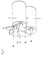
- Fig. 2 shows two superimposed partial mufflers 6 and 7 respectively Fig. 1 ,
- the distributor 4 or 5 profile clamps 9 on For gas-tight connection to the supply line 2 and the discharge line 3 (not shown in each case), the distributor 4 or 5 profile clamps 9 on.
- 5 junctions 16 Depending on the size and volume of the partial muffler 6 and 7 distributor 4; 5 junctions 16 have different diameters. About the junctions 16 reach the exhaust gases from the supply line 2 in the part muffler 6 and 7 or from the part mufflers 6 and 7 in the derivative 3 (each not shown).
- Fig. 3 shows that the distributor 4; 5 according to the Fig. 1 and 2 at the input 12 and at the output 13 in the supply line 2 and the derivative 3 (not shown). passes.
- the reference numerals 16 are the intersections of the distributor 4; 5 in the partial muffler 6; 7 is shown.
Landscapes
- Engineering & Computer Science (AREA)
- Chemical & Material Sciences (AREA)
- Chemical Kinetics & Catalysis (AREA)
- Combustion & Propulsion (AREA)
- Mechanical Engineering (AREA)
- General Engineering & Computer Science (AREA)
- Health & Medical Sciences (AREA)
- Toxicology (AREA)
- Exhaust Silencers (AREA)
Abstract
Description
Gegenstand der Erfindung ist ein Nutzfahrzeug mit einer Abgasanlage mit wenigstens zwei Schalldämpfern entsprechend dem Oberbegriff des Anspruchs 1.The invention relates to a commercial vehicle with an exhaust system with at least two mufflers according to the preamble of claim 1.
Heutige Abgasanlagen sehen vielfach je einen Vorschalldämpfer und einen Hauptschalldämpfer vor, die seriell hintereinander geschaltet sind. Aus
Die oberhalb des Fahrgestellrahmens liegenden Abgassammelrohre sind über jeweils eine Turbine eines Abgasturboladers mit Abgasrohren verbunden, die jeweils zwischen den Längsholmen und dem an die Brennkraftmaschine angeflantschten Getriebe hindurch nach unten führen und in einen unterhalb der Längsholme angeordneten Vorschalldämpfer münden, in den der Hydrolysekatalysator und wenigstens ein Oxidationskatalysator integriert sind. Stromab folgt ein Hauptschalldämpfer mit wenigstens einem integrierten SCR-Katalysator.The exhaust manifolds lying above the chassis frame are each connected to exhaust pipes via a turbine of an exhaust-gas turbocharger, which lead downwards between the longitudinal beams and the gearbox flanked to the internal combustion engine and open into a pre-silencer arranged below the longitudinal beams, into which the hydrolysis catalytic converter and at least one Oxidation catalyst are integrated. Downstream follows a main silencer with at least one integrated SCR catalyst.
Bei den üblichen Konstruktionen müssen die Abgasanlagen für jeden Nutzfahrzeugtyp neu entwickelt und die einzelnen Komponenten an die jeweiligen Gegebenheiten des Fahrzeugtyps angepasst werden. Wünschenswert wäre es bei der Konzeption eines, neuen Nutzfahrzeugtyps auf bestehende Systeme und Komponente zurückgreifen zu können. Es ist daher die Aufgabe der Erfindung die Abgasanlage eines Nutzfahrzeugs entsprechend zu modifizieren.In the conventional constructions, the exhaust systems for each type of commercial vehicle must be redeveloped and the individual components must be adapted to the particular conditions of the vehicle type. It would be desirable in the conception of a new type of commercial vehicle to be able to use existing systems and components. It is therefore the object of the invention to modify the exhaust system of a commercial vehicle accordingly.
Die Aufgabe wird erfindungsgemäß durch die Merkmale des Anspruchs 1 gelöst.The object is achieved by the features of claim 1.
Die Teilschalldämpfer sind als Hauptschalldämpfer ausgelegt. Im Weiteren wird von zwei Teilschalldämpfern ausgegangen, denen jeweils weitere Nachschalldämpfer angegliedert werden können. Die Teilschalldämpfer können dabei parallel übereinander oder nebeneinander angeordnet werden. Zur platzsparenden Anordnung ist nach Maßgabe der Erfindung nur noch eine Zuleitung und eine Ableitung für die vorhandenen Teilschalldämpfer erforderlich. Hierdurch können die Herstellungskosten der Abgasanlage spürbar gesenkt werden. Ein Austausch bzw. die Wartung der Abgasanlage ist einfacher durchführbar. Zwei oder mehrere Teilschalldämpfer können je nach der Abgasmenge und in Abgängigkeit des Reinigungser-fordernisses miteinander kombiniert werden. Hierbei kann bei der Neukonzeption des Nutzfahrzeugs bzw. bei der Wartung auf bekannte Standartteilschalldämpfer zurückgegriffen werden. Vorteilhaft ist, dass angesichts der lediglich jeweils einen erforderlichen Zuleitung bzw. Ableitung die erforderliche Hitzeabschirmung gegenüber benachbarter Bauteile und Aggregate deutlich reduziert werden kann. Zur Anbindung mehreren Teilschalldämpfer an die Zu- bzw. die Ableitung werden wenigstens zwei Verteiler eingesetzt. Die Erfindung ermöglicht den Einsatz mehrerer Gruppen von Abgasanlagen mit wenigstens jeweils zwei Teilschalldämpfem. Ein Rückgriff auf bekannte Serienbauteile für Fahrzeuge und Motoren unterschiedlicher Größe und Abgasausstoß begünstigt die Reduktion der Herstellungskosten des jeweiligen Nutzfahrzeugs.The partial mufflers are designed as main mufflers. In the following, it is assumed that two partial silencers, each of which additional rear silencer can be affiliated. The partial mufflers can be arranged parallel to each other or side by side. For space-saving arrangement according to the invention, only one supply line and a derivative of the existing part muffler is required. As a result, the manufacturing cost of the exhaust system can be noticeably reduced. An exchange or maintenance of the exhaust system is easier to carry out. Two or more partial silencers can be combined depending on the amount of exhaust gas and in pursuit of Reinigungser-demand. This can be used in the redesign of the commercial vehicle or during maintenance on known standard part silencer. It is advantageous that in view of the only one required supply or discharge, the required heat shield with respect to adjacent components and units can be significantly reduced. At least two distributors are used to connect several partial silencers to the inlet and outlet. The invention enables the use of several groups of exhaust systems with at least two partial silencers. A recourse to known series components for vehicles and engines of different sizes and exhaust emissions favors the reduction of manufacturing costs of the respective commercial vehicle.
Nach einer anderen Ausführungsform der Erfindung sind der die Zuleitung mit dem Teilschalldämpfer verbindende Verteiler und der den Teilschalldämpfer mit der Ableitung verbindende Verteiler gleichachsig an derselben Stirnwand des jeweiligen Teilschalldämpfers angeordnet.According to another embodiment of the invention, the distributor connecting the supply line to the partial muffler and the distributor connecting the partial muffler to the discharge line are arranged coaxially on the same end wall of the respective partial muffler.
Nach einer weiteren Ausführungsform der Erfindung sind der die Zuleitung mit den Teilschalldämpfem verbindende Verteiler und der die Teilschalldämpfer mit der Ableitung verbindende Verteiler gleichachsig an einander gegenüberliegenden Stirnwänden der Teilschalldämpfer angeordnet.According to a further embodiment of the invention, the distributor connecting the supply line to the partial silencers and the distributor connecting the partial silencers to the discharge are arranged coaxially on opposite end walls of the partial silencers.
Nach einer weiteren Ausführungsform der Erfindung sind die Teilschalldämpfer identisch ausgebildet.According to a further embodiment of the invention, the partial mufflers are identical.
Nach einer weiteren Ausführungsform der Erfindung sind die Teilschalldämpfer unterschiedlich ausgebildet. Auf diese Weise können im Reparaturfall genormte Teilschalldämpfer unterschiedlicher Größe und unterschiedlichen Volumens ausgetauscht werden.According to a further embodiment of the invention, the partial mufflers are designed differently. In this way, standardized part mufflers of different sizes and different volumes can be replaced in case of repair.
Nachstehend ist die Erfindung anhand mehrerer in der Zeichnung dargestellter Ausführungsbeispiele näher erläutert. Hierbei zeigen:
-
Fig.1 die erfindungsgemäße Abgasanlage mit Zu- und Ableitung, -
Fig. 2 die Schalldämpfer mit je einem Verteiler und -
Fig. 3 einen Verteiler der Abgasanlage.
-
Fig.1 the exhaust system according to the invention with inlet and outlet, -
Fig. 2 the silencers with one distributor each and -
Fig. 3 a distributor of the exhaust system.
Die Zuführung des Abgases zu den Teilschalldämpfern 6 und 7 erfolgt motorseitig über die Zuleitung 2, die mit einem Flansch 8 am Motor (nicht gezeigt) angeordnet ist. Die Abgase werden den beiden Teilschalldämpfern 6,7 über die Zuleitung 2 zugeführt. Die Zuleitung 2 und die Ableitung 3 können aus starren Metallrohren bestehen, die entweder einstückig sind oder aus mehreren durch Profilschellen 9 mit einander verbundenen Einzelstücken 11. Denkbar ist, zur Erhöhung der Flexibilität der Zu- und Ableitung 2 und 3 flexible Zwischenstücke 10 zu verwenden, die beispielhaft aus einem biegsamen Metallschlauch bestehen. Die Verteiler 4 bzw. 5 weisen gegenüber der Zuleitung 2 bzw. der Ableitung 3 je einen Eingang 12 bzw. einen Ausgang 13 auf. Die Verteiler 4; 5 ermöglichen durch Einmündungen 16 den Eintritt des Abgases in die Teilschalldämpfer 6; 7 bzw. den Austritt des gereinigten Abgases aus den Teilschalldämpfern 6; 7 in die Ableitung 3. Jeder Verteiler 4,5 ist dabei mit Hilfe von Profilschellen 9 an den Teilschalldämpfern 6,7 befestigt.The supply of the exhaust gas to the
In der
- 11
- Abgasanlageexhaust system
- 22
- Zuleitungsupply
- 33
- Ableitungderivation
- 44
- Verteiler (Zuleitung)Distributor (supply)
- 55
- Verteiler (Ableitung)Distributor (derivation)
- 66
- Teilschalldämpferpart silencer
- 77
- Teilschalldämpferpart silencer
- 88th
- Flansch/MotorFlange / motor
- 99
- Profilschellenprofile clamps
- 1010
- Zwischenstückconnecting piece
- 1111
- EinzelstückeSingle pieces
- 1212
- Eingangentrance
- 1313
- Ausgangoutput
- 1414
- Auspufföffnungexhaust port
- 1515
- Stirnwandbulkhead
- 1616
- Einmündungjunction
Claims (5)
Applications Claiming Priority (1)
| Application Number | Priority Date | Filing Date | Title |
|---|---|---|---|
| AT0087907A AT505256B1 (en) | 2007-06-04 | 2007-06-04 | EXHAUST SYSTEM WITH 2 MULTI-ASSOCIATED SILENCER |
Publications (3)
| Publication Number | Publication Date |
|---|---|
| EP2017441A1 true EP2017441A1 (en) | 2009-01-21 |
| EP2017441B1 EP2017441B1 (en) | 2011-07-20 |
| EP2017441B8 EP2017441B8 (en) | 2011-11-02 |
Family
ID=39721929
Family Applications (1)
| Application Number | Title | Priority Date | Filing Date |
|---|---|---|---|
| EP08009166A Active EP2017441B8 (en) | 2007-06-04 | 2008-05-17 | Exhaust gas system comprising two parallel arranged dampers |
Country Status (2)
| Country | Link |
|---|---|
| EP (1) | EP2017441B8 (en) |
| AT (2) | AT505256B1 (en) |
Citations (6)
| Publication number | Priority date | Publication date | Assignee | Title |
|---|---|---|---|---|
| JPS60212610A (en) | 1984-04-05 | 1985-10-24 | Hisashi Imai | Exhaust gas purifying device |
| EP0556846A1 (en) | 1992-02-19 | 1993-08-25 | LEISTRITZ AG & CO. Abgastechnik | Exhaust silencer for diesel engines, particularly for commercial vehicles |
| EP0558951A1 (en) * | 1992-02-29 | 1993-09-08 | Iveco Magirus Ag | Exhaust silencer for internal combustion engines |
| DE19743446A1 (en) * | 1997-05-26 | 1998-12-03 | Bayerische Motoren Werke Ag | Exhaust silencing system for internal combustion engine |
| DE102005056423A1 (en) | 2004-12-07 | 2006-06-08 | MAN Nutzfahrzeuge Österreich AG | Exhaust gas evacuation for commercial motor vehicle, has front exhaust silencer between frame longitudinal bar and drive, and main exhaust silencer with SCR-catalyst follows former silencer exhibiting hydrolysis and oxidation catalyst |
| US20060286877A1 (en) * | 2005-06-17 | 2006-12-21 | Kunihiko Kamio | Personal watercraft |
Family Cites Families (2)
| Publication number | Priority date | Publication date | Assignee | Title |
|---|---|---|---|---|
| US3247665A (en) * | 1964-04-02 | 1966-04-26 | Texaco Inc | Catalytic muffler construction for exhaust emission control in an internal combustion engine system |
| US3631792A (en) * | 1970-06-15 | 1972-01-04 | Albert G Bodine | Sonic internal combustion engine exhaust afterburner |
-
2007
- 2007-06-04 AT AT0087907A patent/AT505256B1/en active
-
2008
- 2008-05-17 AT AT08009166T patent/ATE517238T1/en active
- 2008-05-17 EP EP08009166A patent/EP2017441B8/en active Active
Patent Citations (6)
| Publication number | Priority date | Publication date | Assignee | Title |
|---|---|---|---|---|
| JPS60212610A (en) | 1984-04-05 | 1985-10-24 | Hisashi Imai | Exhaust gas purifying device |
| EP0556846A1 (en) | 1992-02-19 | 1993-08-25 | LEISTRITZ AG & CO. Abgastechnik | Exhaust silencer for diesel engines, particularly for commercial vehicles |
| EP0558951A1 (en) * | 1992-02-29 | 1993-09-08 | Iveco Magirus Ag | Exhaust silencer for internal combustion engines |
| DE19743446A1 (en) * | 1997-05-26 | 1998-12-03 | Bayerische Motoren Werke Ag | Exhaust silencing system for internal combustion engine |
| DE102005056423A1 (en) | 2004-12-07 | 2006-06-08 | MAN Nutzfahrzeuge Österreich AG | Exhaust gas evacuation for commercial motor vehicle, has front exhaust silencer between frame longitudinal bar and drive, and main exhaust silencer with SCR-catalyst follows former silencer exhibiting hydrolysis and oxidation catalyst |
| US20060286877A1 (en) * | 2005-06-17 | 2006-12-21 | Kunihiko Kamio | Personal watercraft |
Also Published As
| Publication number | Publication date |
|---|---|
| ATE517238T1 (en) | 2011-08-15 |
| AT505256B1 (en) | 2009-03-15 |
| EP2017441B8 (en) | 2011-11-02 |
| EP2017441B1 (en) | 2011-07-20 |
| AT505256A1 (en) | 2008-12-15 |
Similar Documents
| Publication | Publication Date | Title |
|---|---|---|
| EP1866591B1 (en) | Exhaust gas heat exchanger, in particular an exhaust gas cooler for exhaust gas recirculation in a motor vehicle | |
| EP2287452B1 (en) | Exhaust system for an internal combustion engine | |
| EP2161423B1 (en) | Exhaust gas facility for diesel vehicles with an SCR catalytic converter | |
| EP2527611B1 (en) | Device and method for treating waste gas | |
| DE102012000591A1 (en) | Engine block assembly with an exhaust system | |
| DE112010005012T5 (en) | aftertreatment system | |
| DE102007035556A1 (en) | Mixing apparatus for adding exhaust gas recirculation flow into charge air flow of internal-combustion engine, has connecting tube running transverse through passage channel and connecting inlet opening with one of chambers | |
| EP1776515B1 (en) | Double-flow exhaust system for an internal combustion engine | |
| DE102015011175B4 (en) | Exhaust system for an internal combustion engine | |
| EP3385520A1 (en) | Exhaust gas treatment device for a combustion engine | |
| DE102009032213B4 (en) | Exhaust system of an internal combustion engine | |
| DE102020129001A1 (en) | Exhaust system with exhaust gas turbocharger, ejector and exhaust gas catalytic converter | |
| EP2017441B1 (en) | Exhaust gas system comprising two parallel arranged dampers | |
| WO2019081109A1 (en) | Internal combustion engine with an exhaust gas system | |
| DE102010018087A1 (en) | Waste gas system for V-type six cylinder combustion engine, has inner and outer manifolds integrated into one another such that collection tube of outer manifold encloses collection tube of inner manifold under formation of air gap | |
| DE102013225256B4 (en) | vehicle | |
| DE112020002964B4 (en) | Exhaust system and silencer | |
| EP1510674B1 (en) | Exhaust gas system of an internal combustion engine with integrated pre- and main- silencer | |
| DE102018127624B4 (en) | Method and device for operating an auxiliary heating device of a motor vehicle | |
| DE10329436B4 (en) | Emission control system for an internal combustion engine | |
| DE102008022998B4 (en) | Apparatus and method for purifying exhaust gases for an exhaust line of an internal combustion engine | |
| DE102016101704B4 (en) | Drive system for a vehicle | |
| EP1830044A1 (en) | Exhaust system | |
| DE4403583A1 (en) | Exhaust pipe system | |
| DE19858641A1 (en) | Catalytic converter arrangement on a motor vehicle |
Legal Events
| Date | Code | Title | Description |
|---|---|---|---|
| PUAI | Public reference made under article 153(3) epc to a published international application that has entered the european phase |
Free format text: ORIGINAL CODE: 0009012 |
|
| PUAI | Public reference made under article 153(3) epc to a published international application that has entered the european phase |
Free format text: ORIGINAL CODE: 0009012 |
|
| AK | Designated contracting states |
Kind code of ref document: A1 Designated state(s): AT BE BG CH CY CZ DE DK EE ES FI FR GB GR HR HU IE IS IT LI LT LU LV MC MT NL NO PL PT RO SE SI SK TR |
|
| AX | Request for extension of the european patent |
Extension state: AL BA MK RS |
|
| AKX | Designation fees paid |
Designated state(s): AT BE BG CH CY CZ DE DK EE ES FI FR GB GR HR HU IE IS IT LI LT LU LV MC MT NL NO PL PT RO SE SI SK TR |
|
| 17P | Request for examination filed |
Effective date: 20090828 |
|
| 17Q | First examination report despatched |
Effective date: 20101007 |
|
| GRAP | Despatch of communication of intention to grant a patent |
Free format text: ORIGINAL CODE: EPIDOSNIGR1 |
|
| RIC1 | Information provided on ipc code assigned before grant |
Ipc: F01N 13/04 20100101ALI20110208BHEP Ipc: F01N 3/28 20060101ALI20110208BHEP Ipc: F01N 3/08 20060101AFI20110208BHEP |
|
| GRAS | Grant fee paid |
Free format text: ORIGINAL CODE: EPIDOSNIGR3 |
|
| GRAA | (expected) grant |
Free format text: ORIGINAL CODE: 0009210 |
|
| AK | Designated contracting states |
Kind code of ref document: B1 Designated state(s): AT BE BG CH CY CZ DE DK EE ES FI FR GB GR HR HU IE IS IT LI LT LU LV MC MT NL NO PL PT RO SE SI SK TR |
|
| REG | Reference to a national code |
Ref country code: GB Ref legal event code: FG4D Free format text: NOT ENGLISH |
|
| REG | Reference to a national code |
Ref country code: CH Ref legal event code: EP |
|
| RAP2 | Party data changed (patent owner data changed or rights of a patent transferred) |
Owner name: MAN NUTZFAHRZEUGE OESTERREICH AG |
|
| REG | Reference to a national code |
Ref country code: NL Ref legal event code: T3 |
|
| REG | Reference to a national code |
Ref country code: DE Ref legal event code: R096 Ref document number: 502008004229 Country of ref document: DE Effective date: 20110915 |
|
| REG | Reference to a national code |
Ref country code: SE Ref legal event code: TRGR |
|
| REG | Reference to a national code |
Ref country code: DE Ref legal event code: R081 Ref document number: 502008004229 Country of ref document: DE Owner name: MAN TRUCK & BUS OESTERREICH AG, AT Free format text: FORMER OWNER: MAN NUTZFAHRZEUGE OESTERREICH AG, WIEN, AT Effective date: 20110914 |
|
| PG25 | Lapsed in a contracting state [announced via postgrant information from national office to epo] |
Ref country code: NO Free format text: LAPSE BECAUSE OF FAILURE TO SUBMIT A TRANSLATION OF THE DESCRIPTION OR TO PAY THE FEE WITHIN THE PRESCRIBED TIME-LIMIT Effective date: 20111020 Ref country code: LT Free format text: LAPSE BECAUSE OF FAILURE TO SUBMIT A TRANSLATION OF THE DESCRIPTION OR TO PAY THE FEE WITHIN THE PRESCRIBED TIME-LIMIT Effective date: 20110720 Ref country code: FI Free format text: LAPSE BECAUSE OF FAILURE TO SUBMIT A TRANSLATION OF THE DESCRIPTION OR TO PAY THE FEE WITHIN THE PRESCRIBED TIME-LIMIT Effective date: 20110720 Ref country code: IS Free format text: LAPSE BECAUSE OF FAILURE TO SUBMIT A TRANSLATION OF THE DESCRIPTION OR TO PAY THE FEE WITHIN THE PRESCRIBED TIME-LIMIT Effective date: 20111120 Ref country code: HR Free format text: LAPSE BECAUSE OF FAILURE TO SUBMIT A TRANSLATION OF THE DESCRIPTION OR TO PAY THE FEE WITHIN THE PRESCRIBED TIME-LIMIT Effective date: 20110720 Ref country code: PT Free format text: LAPSE BECAUSE OF FAILURE TO SUBMIT A TRANSLATION OF THE DESCRIPTION OR TO PAY THE FEE WITHIN THE PRESCRIBED TIME-LIMIT Effective date: 20111121 |
|
| REG | Reference to a national code |
Ref country code: IE Ref legal event code: FD4D |
|
| RAP2 | Party data changed (patent owner data changed or rights of a patent transferred) |
Owner name: MAN TRUCK & BUS OESTERREICH AG |
|
| PG25 | Lapsed in a contracting state [announced via postgrant information from national office to epo] |
Ref country code: LV Free format text: LAPSE BECAUSE OF FAILURE TO SUBMIT A TRANSLATION OF THE DESCRIPTION OR TO PAY THE FEE WITHIN THE PRESCRIBED TIME-LIMIT Effective date: 20110720 Ref country code: SI Free format text: LAPSE BECAUSE OF FAILURE TO SUBMIT A TRANSLATION OF THE DESCRIPTION OR TO PAY THE FEE WITHIN THE PRESCRIBED TIME-LIMIT Effective date: 20110720 Ref country code: PL Free format text: LAPSE BECAUSE OF FAILURE TO SUBMIT A TRANSLATION OF THE DESCRIPTION OR TO PAY THE FEE WITHIN THE PRESCRIBED TIME-LIMIT Effective date: 20110720 Ref country code: CY Free format text: LAPSE BECAUSE OF FAILURE TO SUBMIT A TRANSLATION OF THE DESCRIPTION OR TO PAY THE FEE WITHIN THE PRESCRIBED TIME-LIMIT Effective date: 20110720 Ref country code: GR Free format text: LAPSE BECAUSE OF FAILURE TO SUBMIT A TRANSLATION OF THE DESCRIPTION OR TO PAY THE FEE WITHIN THE PRESCRIBED TIME-LIMIT Effective date: 20111021 |
|
| REG | Reference to a national code |
Ref country code: NL Ref legal event code: TD Effective date: 20120223 |
|
| REG | Reference to a national code |
Ref country code: DE Ref legal event code: R081 Ref document number: 502008004229 Country of ref document: DE Owner name: MAN TRUCK & BUS OESTERREICH AG, AT Free format text: FORMER OWNER: MAN NUTZFAHRZEUGE OESTERREICH AG, STEYR, AT Effective date: 20120125 |
|
| PG25 | Lapsed in a contracting state [announced via postgrant information from national office to epo] |
Ref country code: SK Free format text: LAPSE BECAUSE OF FAILURE TO SUBMIT A TRANSLATION OF THE DESCRIPTION OR TO PAY THE FEE WITHIN THE PRESCRIBED TIME-LIMIT Effective date: 20110720 Ref country code: IE Free format text: LAPSE BECAUSE OF FAILURE TO SUBMIT A TRANSLATION OF THE DESCRIPTION OR TO PAY THE FEE WITHIN THE PRESCRIBED TIME-LIMIT Effective date: 20110720 Ref country code: CZ Free format text: LAPSE BECAUSE OF FAILURE TO SUBMIT A TRANSLATION OF THE DESCRIPTION OR TO PAY THE FEE WITHIN THE PRESCRIBED TIME-LIMIT Effective date: 20110720 |
|
| PLBE | No opposition filed within time limit |
Free format text: ORIGINAL CODE: 0009261 |
|
| STAA | Information on the status of an ep patent application or granted ep patent |
Free format text: STATUS: NO OPPOSITION FILED WITHIN TIME LIMIT |
|
| PG25 | Lapsed in a contracting state [announced via postgrant information from national office to epo] |
Ref country code: RO Free format text: LAPSE BECAUSE OF FAILURE TO SUBMIT A TRANSLATION OF THE DESCRIPTION OR TO PAY THE FEE WITHIN THE PRESCRIBED TIME-LIMIT Effective date: 20110720 Ref country code: EE Free format text: LAPSE BECAUSE OF FAILURE TO SUBMIT A TRANSLATION OF THE DESCRIPTION OR TO PAY THE FEE WITHIN THE PRESCRIBED TIME-LIMIT Effective date: 20110720 |
|
| 26N | No opposition filed |
Effective date: 20120423 |
|
| PG25 | Lapsed in a contracting state [announced via postgrant information from national office to epo] |
Ref country code: DK Free format text: LAPSE BECAUSE OF FAILURE TO SUBMIT A TRANSLATION OF THE DESCRIPTION OR TO PAY THE FEE WITHIN THE PRESCRIBED TIME-LIMIT Effective date: 20110720 |
|
| REG | Reference to a national code |
Ref country code: DE Ref legal event code: R097 Ref document number: 502008004229 Country of ref document: DE Effective date: 20120423 |
|
| BERE | Be: lapsed |
Owner name: MAN NUTZFAHRZEUGE OSTERREICH AG Effective date: 20120531 |
|
| PG25 | Lapsed in a contracting state [announced via postgrant information from national office to epo] |
Ref country code: MC Free format text: LAPSE BECAUSE OF NON-PAYMENT OF DUE FEES Effective date: 20120531 |
|
| REG | Reference to a national code |
Ref country code: CH Ref legal event code: PL |
|
| PG25 | Lapsed in a contracting state [announced via postgrant information from national office to epo] |
Ref country code: LI Free format text: LAPSE BECAUSE OF NON-PAYMENT OF DUE FEES Effective date: 20120531 Ref country code: CH Free format text: LAPSE BECAUSE OF NON-PAYMENT OF DUE FEES Effective date: 20120531 |
|
| PG25 | Lapsed in a contracting state [announced via postgrant information from national office to epo] |
Ref country code: BE Free format text: LAPSE BECAUSE OF NON-PAYMENT OF DUE FEES Effective date: 20120531 |
|
| PG25 | Lapsed in a contracting state [announced via postgrant information from national office to epo] |
Ref country code: ES Free format text: LAPSE BECAUSE OF FAILURE TO SUBMIT A TRANSLATION OF THE DESCRIPTION OR TO PAY THE FEE WITHIN THE PRESCRIBED TIME-LIMIT Effective date: 20111031 |
|
| PG25 | Lapsed in a contracting state [announced via postgrant information from national office to epo] |
Ref country code: BG Free format text: LAPSE BECAUSE OF FAILURE TO SUBMIT A TRANSLATION OF THE DESCRIPTION OR TO PAY THE FEE WITHIN THE PRESCRIBED TIME-LIMIT Effective date: 20111020 |
|
| PG25 | Lapsed in a contracting state [announced via postgrant information from national office to epo] |
Ref country code: MT Free format text: LAPSE BECAUSE OF FAILURE TO SUBMIT A TRANSLATION OF THE DESCRIPTION OR TO PAY THE FEE WITHIN THE PRESCRIBED TIME-LIMIT Effective date: 20110720 |
|
| PG25 | Lapsed in a contracting state [announced via postgrant information from national office to epo] |
Ref country code: LU Free format text: LAPSE BECAUSE OF NON-PAYMENT OF DUE FEES Effective date: 20120517 |
|
| PG25 | Lapsed in a contracting state [announced via postgrant information from national office to epo] |
Ref country code: HU Free format text: LAPSE BECAUSE OF FAILURE TO SUBMIT A TRANSLATION OF THE DESCRIPTION OR TO PAY THE FEE WITHIN THE PRESCRIBED TIME-LIMIT Effective date: 20080517 |
|
| REG | Reference to a national code |
Ref country code: FR Ref legal event code: PLFP Year of fee payment: 9 |
|
| REG | Reference to a national code |
Ref country code: FR Ref legal event code: PLFP Year of fee payment: 10 |
|
| REG | Reference to a national code |
Ref country code: FR Ref legal event code: PLFP Year of fee payment: 11 |
|
| REG | Reference to a national code |
Ref country code: DE Ref legal event code: R081 Ref document number: 502008004229 Country of ref document: DE Owner name: MAN TRUCK & BUS SE, DE Free format text: FORMER OWNER: MAN TRUCK & BUS OESTERREICH AG, STEYR, AT |
|
| REG | Reference to a national code |
Ref country code: AT Ref legal event code: PC Ref document number: 517238 Country of ref document: AT Kind code of ref document: T Owner name: MAN TRUCK & BUS SE, DE Effective date: 20211123 |
|
| REG | Reference to a national code |
Ref country code: GB Ref legal event code: 732E Free format text: REGISTERED BETWEEN 20220421 AND 20220427 |
|
| PGFP | Annual fee paid to national office [announced via postgrant information from national office to epo] |
Ref country code: SE Payment date: 20230317 Year of fee payment: 16 |
|
| PGFP | Annual fee paid to national office [announced via postgrant information from national office to epo] |
Ref country code: NL Payment date: 20230525 Year of fee payment: 16 Ref country code: IT Payment date: 20230525 Year of fee payment: 16 Ref country code: FR Payment date: 20230523 Year of fee payment: 16 Ref country code: DE Payment date: 20230530 Year of fee payment: 16 |
|
| PGFP | Annual fee paid to national office [announced via postgrant information from national office to epo] |
Ref country code: AT Payment date: 20230519 Year of fee payment: 16 |
|
| PGFP | Annual fee paid to national office [announced via postgrant information from national office to epo] |
Ref country code: GB Payment date: 20230523 Year of fee payment: 16 |
|
| REG | Reference to a national code |
Ref country code: NL Ref legal event code: PD Owner name: MAN TRUCK & BUS OESTERREICH GESMBH; AT Free format text: DETAILS ASSIGNMENT: CHANGE OF OWNER(S), ASSIGNMENT; FORMER OWNER NAME: MAN TRUCK & BUS OESTERREICH GESMBH Effective date: 20231031 |
|
| PGFP | Annual fee paid to national office [announced via postgrant information from national office to epo] |
Ref country code: TR Payment date: 20240507 Year of fee payment: 17 |