EP2017371A1 - Wasserstofferzeugungsverfahren mittels Doppeldruck-Multistufenelektrolyse - Google Patents
Wasserstofferzeugungsverfahren mittels Doppeldruck-Multistufenelektrolyse Download PDFInfo
- Publication number
- EP2017371A1 EP2017371A1 EP08012190A EP08012190A EP2017371A1 EP 2017371 A1 EP2017371 A1 EP 2017371A1 EP 08012190 A EP08012190 A EP 08012190A EP 08012190 A EP08012190 A EP 08012190A EP 2017371 A1 EP2017371 A1 EP 2017371A1
- Authority
- EP
- European Patent Office
- Prior art keywords
- mpa
- pressure
- electrolyzer
- reactor
- sulfur
- Prior art date
- Legal status (The legal status is an assumption and is not a legal conclusion. Google has not performed a legal analysis and makes no representation as to the accuracy of the status listed.)
- Withdrawn
Links
Images




Classifications
-
- C—CHEMISTRY; METALLURGY
- C25—ELECTROLYTIC OR ELECTROPHORETIC PROCESSES; APPARATUS THEREFOR
- C25B—ELECTROLYTIC OR ELECTROPHORETIC PROCESSES FOR THE PRODUCTION OF COMPOUNDS OR NON-METALS; APPARATUS THEREFOR
- C25B1/00—Electrolytic production of inorganic compounds or non-metals
- C25B1/01—Products
- C25B1/02—Hydrogen or oxygen
-
- C—CHEMISTRY; METALLURGY
- C01—INORGANIC CHEMISTRY
- C01B—NON-METALLIC ELEMENTS; COMPOUNDS THEREOF; METALLOIDS OR COMPOUNDS THEREOF NOT COVERED BY SUBCLASS C01C
- C01B17/00—Sulfur; Compounds thereof
- C01B17/48—Sulfur dioxide; Sulfurous acid
- C01B17/50—Preparation of sulfur dioxide
- C01B17/56—Separation; Purification
-
- C—CHEMISTRY; METALLURGY
- C01—INORGANIC CHEMISTRY
- C01B—NON-METALLIC ELEMENTS; COMPOUNDS THEREOF; METALLOIDS OR COMPOUNDS THEREOF NOT COVERED BY SUBCLASS C01C
- C01B13/00—Oxygen; Ozone; Oxides or hydroxides in general
- C01B13/02—Preparation of oxygen
-
- C—CHEMISTRY; METALLURGY
- C01—INORGANIC CHEMISTRY
- C01B—NON-METALLIC ELEMENTS; COMPOUNDS THEREOF; METALLOIDS OR COMPOUNDS THEREOF NOT COVERED BY SUBCLASS C01C
- C01B5/00—Water
-
- C—CHEMISTRY; METALLURGY
- C25—ELECTROLYTIC OR ELECTROPHORETIC PROCESSES; APPARATUS THEREFOR
- C25B—ELECTROLYTIC OR ELECTROPHORETIC PROCESSES FOR THE PRODUCTION OF COMPOUNDS OR NON-METALS; APPARATUS THEREFOR
- C25B1/00—Electrolytic production of inorganic compounds or non-metals
- C25B1/01—Products
- C25B1/02—Hydrogen or oxygen
- C25B1/04—Hydrogen or oxygen by electrolysis of water
-
- Y—GENERAL TAGGING OF NEW TECHNOLOGICAL DEVELOPMENTS; GENERAL TAGGING OF CROSS-SECTIONAL TECHNOLOGIES SPANNING OVER SEVERAL SECTIONS OF THE IPC; TECHNICAL SUBJECTS COVERED BY FORMER USPC CROSS-REFERENCE ART COLLECTIONS [XRACs] AND DIGESTS
- Y02—TECHNOLOGIES OR APPLICATIONS FOR MITIGATION OR ADAPTATION AGAINST CLIMATE CHANGE
- Y02E—REDUCTION OF GREENHOUSE GAS [GHG] EMISSIONS, RELATED TO ENERGY GENERATION, TRANSMISSION OR DISTRIBUTION
- Y02E60/00—Enabling technologies; Technologies with a potential or indirect contribution to GHG emissions mitigation
- Y02E60/30—Hydrogen technology
- Y02E60/36—Hydrogen production from non-carbon containing sources, e.g. by water electrolysis
-
- Y—GENERAL TAGGING OF NEW TECHNOLOGICAL DEVELOPMENTS; GENERAL TAGGING OF CROSS-SECTIONAL TECHNOLOGIES SPANNING OVER SEVERAL SECTIONS OF THE IPC; TECHNICAL SUBJECTS COVERED BY FORMER USPC CROSS-REFERENCE ART COLLECTIONS [XRACs] AND DIGESTS
- Y02—TECHNOLOGIES OR APPLICATIONS FOR MITIGATION OR ADAPTATION AGAINST CLIMATE CHANGE
- Y02P—CLIMATE CHANGE MITIGATION TECHNOLOGIES IN THE PRODUCTION OR PROCESSING OF GOODS
- Y02P20/00—Technologies relating to chemical industry
- Y02P20/10—Process efficiency
- Y02P20/129—Energy recovery, e.g. by cogeneration, H2recovery or pressure recovery turbines
Definitions
- the sulfur cycles are a group of thermochemical processes that can make hydrogen, mainly using high temperature thermal energy from a high temperature heat source.
- the Westinghouse Sulfur Process also known as the HyS or Hybrid Sulfur Process
- FIG 1 and the Sulfur Iodine (S/I) Process, FIG. 2 are two processes in this category.
- the high temperature heat sources are any that produce heat, available for use, above about 800°C, such as a High-Temperature Gas-Cooled Nuclear Reactor (HTGR) or a natural gas fired combustor.
- HTGR High-Temperature Gas-Cooled Nuclear Reactor
- the Westinghouse Sulfur Process produces hydrogen in a low-temperature electrochemical step, in which sulfuric acid and hydrogen are produced from sulfurous acid. This reaction can be run at between 0.17 and 0.6 volts with a current density of about 500 ma/sq.cm at about 60° C.
- the second step in the cycle is the high temperature decomposition of sulfuric acid at 760°C or above.
- Previous work by Westinghouse has identified catalysts and process designs to carry out this reaction in concert with an HTGR such as the PBMR.
- the final step in this process is absorption of the SO 2 in water at room temperature to form sulfurous acid and a SO 2 free stream of O 2 .
- the Iodine/Sulfur Process also starts with a reversible reaction where sulfuric acid is decomposed at over 760° C to form sulfur dioxide as above, followed by the reaction of the sulfur dioxide with Iodine to form HI.
- This is a well known process which is hereby defined as "standard S/I":
- the hot gas from the primary loop of a HTGR is sent to a Power Conversion Unit (PCU), consisting of a set of gas turbines where the remaining energy is extracted.
- PCU Power Conversion Unit
- the temperature of the gas is no longer high enough to take full advantage of the high efficiencies available from preferred Brayton cycle gas turbines.
- the preheating/vaporization unit, 20 in FIG. 1 presents a severe materials issue as well. As it is evaporated, water is boiled off first, so that this stream changes in the Preheater from a relatively dilute H 2 SO 4 solution of around 30% to 50% by weight, to a concentrated solution of 80% to 95% by weight H 2 SO 4 when the highest temperatures are reached. While there are materials that can operate at the required temperatures (200° to 700°C), they are very expensive.
- Another inefficiency that is built into the process is evaporation and condensation of water that enters with the feed H 2 SO 4 .
- the sulfuric acid feed is typically 30% to 50% weight, so that a large amount of water is preheated and evaporated, only to be condensed and recirculated. The heat of vaporization of this water represents another substantial energy penalty.
- the decomposition process is typically aided by the presence of catalysts, and any water in the feed to the decomposition process can significantly reduce the decomposition catalyst life.
- the SO 2 /O 2 /H 2 O stream is sent to the SO 2 scrubber and O 2 recovery until, generally shown as 14 in FIG. 1 , where SO 2 is absorbed into water to make sulfurous acid (H 2 O + SO 2 ⁇ H 2 SO 3 ).
- This sulfurous acid is then fed to an aqueous phase electrolysis cell, 16 in FIG. 1 , where the sulfurous acid is oxidized to sulfuric acid, generating hydrogen product (2H 2 O+ SO 2 ⁇ H 2 + H 2 SO 4 ).
- the SO 2 In order for the electrolysis step to work efficiently, the SO 2 must remain dissolved in the water. Sulfur dioxide has a limited aqueous solubility.
- Increasing the pressure increases the amount of SO 2 that can be absorbed into the scrubber solution, decreases the level of SO 2 in the O 2 product, and decreases the amount of makeup SO 2 that must be provided.
- increasing pressure also increases the cost of the process equipment, especially the vessels that contain the electrolysis units.
- a hybrid sulfur process that utilizes a dual pressure system comprising a H 2 SO 4 vaporization unit, a H 2 SO 4 disassociation decomposition reactor operating at a pressure of from 7 MPa to 9 MPa, a product cooler and an SO 2 recovery process that also generates O 2 , operating at a pressure of 0.1 MPa to 7MPa feeding to an electrolyzer producing H 2 at same pressure.
- This invention also resides in a hybrid sulfur process which comprises (a) a sulfur cycle, selected from the group consisting of a Westinghouse Sulfur Process and a Sulfur Iodine Process, comprising an electrolyzer which provides H 2 SO 4 liquid to a H 2 SO 4 vaporizer reactor operating at a pressure of from 1 MPa to 9 MPa and a temperature effective to provide vaporized gaseous H 2 SO 4 which is decomposed to gaseous H 2 O, SO 2 and O 2 in a decomposition reactor operating at a pressure of from 7 MPa to 9Mpa, which gases are passed to at least one SO 2 scrubber unit(s) operated with at least one electrolyzer unit, where input electricity to the electrolyzer unit(s) result in the production of hydrogen gas and H 2 SO 4 liquid, where both the SO 2 scrubber unit(s) and the electrolyzer units operate at a pressure of 0.1 MPa to 7 MPa; (b) Rankine Cycle Power Conversion Unit, which supplies electricity to at least the electrolyzer unit(s
- FIG. 1 is a prior art block diagram of a Westinghouse Sulfur Process
- FIG. 2 is a prior art block diagram of a Sulfur Iodine Process
- FIG. 3 which best describes the invention is one example of an integrated flow diagram of a hybrid sulfur process using a Rankine Cycle and hydrogen production;
- FIG. 4 illustrates the operation of an actual Rankine cycle
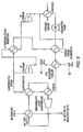
- FIG. 5 is a block diagram illustrating the interconnection of PCU and Hybrid Sulfur Systems to minimize thermal energy losses
- FIG. 6 is a block diagram illustrating a multistage SO 2 absorber electrolysis system in parallel.
- FIG. 7 is an integrated H 2 SO 4 concentrator and H 2 S decomposition reactors.
- FIG. 1 illustrates a standard WSP process 2 shown operating at less than 900 psi.
- the standard S/I process 4 is shown operating at less than 900 psi.
- thermal energy 10 at about 760°C to 1000°C is passed into oxygen generator/sulfuric acid Decomposition Reactor 12 to provide the reaction shown, passing H 2 O, SO 2 and O 2 to an oxygen recovery/SO 2 scrubber unit 14 where H 2 O and SO 2 are passed to an electrolyzer 16 energized with D.C. electricity 18 to provide H 2 shown as 6 and H 2 SO 4 , where the latter is vaporized in preheater/vaporizer 20 by thermal energy 22 to feed vaporized H 2 SO 4 to the oxygen generator/sulfuric acid decomposition reactor 12, as shown.
- a Sakuri 2000 process schematic of the reactions for S/I vs. temperature Sulfuric acid 26 is vaporized in vaporizer 28 and then passed to decomposition reactor 30 at about 760°C to 810°C to generate O 2 and pass O 2 , H 2 O and SO 2 to iodine reactor 32 which generates HI which is decomposed in second decomposition reactor 34 to provide H 2 shown as 6 after passing through the excess I 2 separator 36.
- the decomposition reactor 34 provides the main source of I 2 , shown as 38 for the iodine reactor 32, also known as a Bunsen reactor.
- SO 2 can be removed from the system in Unit 14 at temperatures above 20°C to 75°C, without the use of energetically inefficient refrigeration systems or excess water. More detail can be found in U.S. Publication No. 2006/0002843 A1 (Lahoda et al. )
- the first is to use an integrated process that preferably uses a steam based Rankine Cycle for electrical generation. This unusual approach is shown in FIG. 3 .
- a Brayton cycle utilizing a gas turbine is more efficient that a Rankine cycle that uses steam as an intermediate fluid between the high temperature hot gas source and the Turbine.
- the Rankine cycle becomes more efficient than the Brayton cycle. This is the case when using the high temperature heat source to first decompose H 2 SO 4 .
- the resulting temperature is about 750°C and results, surprisingly, in a Rankine cycle effectiveness that is greater than Brayton effectiveness.
- Cooling the SO 2 /O 2 /H 2 O mixture to 90°C, in or before Unit 14, from the outlet temperature of the H 2 SO 4 reactor 12 amounts to a considerable heat duty, (See Table 1 below): Table 1 Effect of Pressure on Energy Delivered to Power Conversion unit (PCT) and Net WSP Process Efficiency Pressure (MPa) SO x Stream Temperature to SO 2 Scubber Cooler (°C) MW(t) Transferred to PCU/Total Available Hydrogen Production Rate (kg/sec) WSP Process Efficiency 9 262 59.2/59.2 0.797 42.0% 8 259 61.4/61.4 0.778 42.0% 7 255 63.7/65.2 0.748 41.5% 6 249 60.5/66.4 0.725 40.3% 5 240 56.1/70.5 0.704 38.9% 4 229 50.7/71.2 0.682 37.3%
- heat from the SO 2 /O 2 /H 2 O mixture is cooled using a water cooled heat exchanger/SO 2 scrubber unit, 14 of FIG. 1 , by using the hot SO 2 /O 2 /H 2 O stream to preheat the feed water to the Rankine cycle power conversion unit, as shown in FIG. 3 , heat can be beneficially used.
- the amount of heat that can be beneficially used depends upon the inlet temperature of the SO 2 /O 2 /H 2 O stream and on the boiling temperature of the Rankine cycle. The temperatures of these streams in turn depend upon the pressures in the Decomposition Reactor and Rankine cycle boiler.
- the T-S diagram in FIG. 4 shows an actual cycle.
- the path shown as (1') to (1) represents the pumping of the working fluid back to the high pressure of the boiler.
- the path shown as (1) to (2) represents the preheating of the boiler feedwater carried out by the SO 2 /O 2 /H 2 O stream.
- the path shown as (2) to (3) represents the boiling of the water by the hot He from the exit of the decomposition reactor. Since a wet vapor will erode the turbine blades, the vapor is usually superheated to condition (4).
- the expansion may have some inefficiencies and hence not be adiabatic and reversible, so that the expansion step is shown in path (4) to (5) as having a slight increase in entropy.
- the vapor leaving the turbine may not be saturated so that the omitted portion of the heat exchanger removes sensible heat from the vapor as in step (5) to (5'). More detail can be found in Equilibrium Thermodynamics, James Coull and Edward Stuart, John Wiley & Sons, 1964, pages 344-346 .
- the Decomposition Reactor, 12 in FIG. 1 is operated at 7 to 9 MPa , where essentially all of the SO x cooling duty can be recovered as PCU-Rankine Cycle-feed water preheat.
- the pressure of this portion of the system, Units 14 and 16 in FIG. 1 is reduced below the Decomposition Reactor 12 pressure of 7 to 9 MPa.
- FIG. 6 a multi-staged SO 2 absorption/electrolysis process is proposed as a preferred embodiment, as shown in FIG. 6 .
- the figure illustrates a system with three parallel, 14', 14', 14'/16', 16', 16', SO 2 absorber-absorption/electrolysis stages, although as many stages as are necessary to produce the desired SO 2 in O 2 level can be used-a plurality of preferably parallel stages.
- SO 2 is absorbed and electrolyzed to H 2 SO 4 in several stages.
- the sulfuric acid leaving each electrolysis stage is therefore depleted in SO 2 , allowing the acid to be efficiently used as the scrubbing liquor for the next absorption stage in the cascade.
- Nuclear reactor or gas fired combustor 40 shown here as a PBMR, provides fluid heat 42, here He at 950°C to a first intermediate heat exchanger 44 which passes heat 46 to a hybrid sulfur process such as shown in FIGS 1 or 2 , here a WSP 2 and also passes heat 48 to a Rankine Cycle PCU 50, at about 776°C. Any fluid heat 52, out of the WSP, 2, is passed back to the first intermediate heat exchanger 44. Electrical power 54 from the Rankine Cycle 50 is used to power an electrolyzer, shown in FIG 1 as Unit 16, in the WSP, 2. The Rankine Cycle passes cooled fluid heat 56 back to PBMR, 40, all as shown in FIG. 3 in complete detail including He temperatures an energy data.
- a WSP comprises: (1) a sulfur cycle, preferably a Westinghouse Sulfur Process 2 comprising an electrolyzer 16 which provides H 2 SO 4 liquid to a H 2 SO 4 preheater/vaporizer/decomposition reactor 20, shown in FIG.
- H 2 SO 4 comprising H 2 O, SO 2 and O 2 is passed preferably to a plurality of SO 2 scrubber units 14' operated in parallel with a plurality of electrolyzer units 16', as shown in FIG.
- Rankine Cycle Power Conversion Unit 50 which supplies electricity to the sulfur cycle and the plurality of electrolyzer units
- a heat source 40 selected from the group consisting of a nuclear reactor and a gas fired combustor which supply fluid heat to the Rankine Cycle Unit 50 and the sulfur cycle.
- the heat source is preferably a nuclear reactor.
- FIG. 5 generally shows how the heat from the hot SO 2 /O 2 /H 2 O stream is integrated into the operation of the Rankine Cycle, also shown as 50 in FIG. 3 . It also shows how the heat from the gas exiting the decomposition reactor is used to heat the feed water, from feedwater pump shown, to steam. Note that FIG. 5 show a two stage Rankine Turbine Cycle with superheat and reheat. Any number of steam turbine stages with appropriate super and preheat stages can be used as is necessary while still being covered by this invention. In FIG. 5 , 60 shows cold SO 2 /O 2 /H 2 O which will pass to the multistage SO 2 absorber and 62 shows hot SO 2 /O 2 /H 2 O from the outlet of the decomposition reactor.
- a further advance is to use a direct contact heat exchanger and H 2 SO 4 concentrator for the decomposition reactor feed system.
- Traditional heat exchangers would require very large heat exchange areas and result in very expensive and large pieces of equipment.
- Use of indirect heat exchange is limited by internal temperature pinches i.e. a point in the heat exchanger where the fluid temperature of the high temperature side approaches the temperature of the low temperature side due to phase changes occurring on both sides of the Preheater.
- the process produces a very concentrated (80% to 95%) H 2 SO 4 feed stream for the Decomposition Reactor, shown as 12 in FIG. 1 , (significantly reducing the energy duty for evaporating excess water), and efficiently exchanges energy between the Decomposition Reactor products and the feeds.
- FIG. 7 illustrates one potential arrangement of the direct contact concentrator, above in gravity relationship with, decomposition reactors.
- the recycle sulfuric acid is further reduced in pressure with respect to the absorption/electrolysis section to atmospheric pressure. This reduces the cost of the acid storage tank, and allows dissolved O 2 and reduced SO 2 to off-gas from the acid, reducing the corrosivity of the Decomposition Reactor feed and improving the conversion of the H 2 SO 4 to SO 2 /O 2 /H 2 O, by removing excess products from the feed.
Landscapes
- Chemical & Material Sciences (AREA)
- Organic Chemistry (AREA)
- Inorganic Chemistry (AREA)
- Engineering & Computer Science (AREA)
- Chemical Kinetics & Catalysis (AREA)
- Electrochemistry (AREA)
- Materials Engineering (AREA)
- Metallurgy (AREA)
- Electrolytic Production Of Non-Metals, Compounds, Apparatuses Therefor (AREA)
- Treating Waste Gases (AREA)
Applications Claiming Priority (1)
| Application Number | Priority Date | Filing Date | Title |
|---|---|---|---|
| US11/778,863 US7976693B2 (en) | 2006-07-17 | 2007-07-17 | Hydrogen generation process with dual pressure multi stage electrolysis |
Publications (1)
| Publication Number | Publication Date |
|---|---|
| EP2017371A1 true EP2017371A1 (de) | 2009-01-21 |
Family
ID=39791387
Family Applications (1)
| Application Number | Title | Priority Date | Filing Date |
|---|---|---|---|
| EP08012190A Withdrawn EP2017371A1 (de) | 2007-07-17 | 2008-07-05 | Wasserstofferzeugungsverfahren mittels Doppeldruck-Multistufenelektrolyse |
Country Status (5)
| Country | Link |
|---|---|
| US (1) | US7976693B2 (de) |
| EP (1) | EP2017371A1 (de) |
| JP (1) | JP5394019B2 (de) |
| KR (1) | KR101450343B1 (de) |
| CN (1) | CN101348917B (de) |
Families Citing this family (5)
| Publication number | Priority date | Publication date | Assignee | Title |
|---|---|---|---|---|
| FI122606B (fi) * | 2009-05-25 | 2012-04-13 | Outotec Oyj | Menetelmä laimean rikkihapon väkevöimiseksi sekä väkevöintilaitteisto laimean rikkihapon väkevöimiseksi |
| US8709229B2 (en) * | 2010-01-07 | 2014-04-29 | Savannah River Nuclear Solutions, Llc | Method to prevent sulfur accumulation in membrane electrode assembly |
| US8956526B2 (en) | 2012-08-09 | 2015-02-17 | Savannah Nuclear Solutions, Llc | Hybrid sulfur cycle operation for high-temperature gas-cooled reactors |
| JP7059063B2 (ja) * | 2018-03-23 | 2022-04-25 | 株式会社東芝 | 洗浄器、水素製造装置及び電力供給システム |
| CN110578564A (zh) * | 2018-06-08 | 2019-12-17 | 张建城 | 太阳能燃气互补联合风电制备合成气循环热发电装置 |
Citations (6)
| Publication number | Priority date | Publication date | Assignee | Title |
|---|---|---|---|---|
| US3888750A (en) * | 1974-01-29 | 1975-06-10 | Westinghouse Electric Corp | Electrolytic decomposition of water |
| US20060002845A1 (en) | 2004-06-30 | 2006-01-05 | Lahoda Edward J | Sulfuric acid process |
| US20060002843A1 (en) | 2002-12-31 | 2006-01-05 | 3M Innovative Properties Company | Emulsions including surface-modified organic molecules |
| US20060013761A1 (en) * | 2004-07-01 | 2006-01-19 | Westinghouse Electric Company Llc | Isolated hydrogen production process |
| WO2007004997A1 (en) * | 2005-06-30 | 2007-01-11 | Westinghouse Electric Company, Llc | Gas phase electrolyzer process for producing hydrogen |
| US20070007147A1 (en) * | 2005-07-07 | 2007-01-11 | Westinghouse Electric Company Llc | Multiple phase SO3/SO2/H2O/H2SO4 electrolyzer |
Family Cites Families (11)
| Publication number | Priority date | Publication date | Assignee | Title |
|---|---|---|---|---|
| US4412895A (en) * | 1981-09-29 | 1983-11-01 | Westinghouse Electric Corp. | System using SO2 as an anode depolarizer in a solid oxide electrolyte electrolysis cell for H2 production from steam |
| US5492777A (en) * | 1995-01-25 | 1996-02-20 | Westinghouse Electric Corporation | Electrochemical energy conversion and storage system |
| JP4327469B2 (ja) * | 2003-01-24 | 2009-09-09 | 株式会社東芝 | 発電・水素生成組合せプラント |
| JP3708924B2 (ja) * | 2003-01-30 | 2005-10-19 | 核燃料サイクル開発機構 | 熱・電気併用による化学的水素製造方法 |
| US20050000825A1 (en) * | 2003-07-04 | 2005-01-06 | Japan Atomic Energy Research Institute | Process for efficient hydrogen production by thermochemical water splitting using iodine and sulfur dioxide |
| JP4468092B2 (ja) * | 2004-06-30 | 2010-05-26 | 株式会社東芝 | 水素製造装置 |
| WO2006110780A2 (en) * | 2005-04-12 | 2006-10-19 | University Of South Carolina | Production of low temperature electrolytic hydrogen |
| US20060272956A1 (en) * | 2005-05-31 | 2006-12-07 | Felder Mitchell S | Dual hydrogen production apparatus |
| CN100400412C (zh) * | 2005-10-14 | 2008-07-09 | 浙江大学 | 硫碘开路循环制氢的工艺方法 |
| US7491309B2 (en) * | 2005-12-21 | 2009-02-17 | General Electric Company | System and method for the production of hydrogen |
| JP2008223098A (ja) * | 2007-03-13 | 2008-09-25 | Ihi Corp | 水素製造装置 |
-
2007
- 2007-07-17 US US11/778,863 patent/US7976693B2/en not_active Expired - Fee Related
-
2008
- 2008-06-26 KR KR1020080060685A patent/KR101450343B1/ko not_active Expired - Fee Related
- 2008-07-05 EP EP08012190A patent/EP2017371A1/de not_active Withdrawn
- 2008-07-07 CN CN2008101356380A patent/CN101348917B/zh not_active Expired - Fee Related
- 2008-07-16 JP JP2008185030A patent/JP5394019B2/ja not_active Expired - Fee Related
Patent Citations (6)
| Publication number | Priority date | Publication date | Assignee | Title |
|---|---|---|---|---|
| US3888750A (en) * | 1974-01-29 | 1975-06-10 | Westinghouse Electric Corp | Electrolytic decomposition of water |
| US20060002843A1 (en) | 2002-12-31 | 2006-01-05 | 3M Innovative Properties Company | Emulsions including surface-modified organic molecules |
| US20060002845A1 (en) | 2004-06-30 | 2006-01-05 | Lahoda Edward J | Sulfuric acid process |
| US20060013761A1 (en) * | 2004-07-01 | 2006-01-19 | Westinghouse Electric Company Llc | Isolated hydrogen production process |
| WO2007004997A1 (en) * | 2005-06-30 | 2007-01-11 | Westinghouse Electric Company, Llc | Gas phase electrolyzer process for producing hydrogen |
| US20070007147A1 (en) * | 2005-07-07 | 2007-01-11 | Westinghouse Electric Company Llc | Multiple phase SO3/SO2/H2O/H2SO4 electrolyzer |
Non-Patent Citations (4)
| Title |
|---|
| DATABASE COMPENDEX [online] ENGINEERING INFORMATION, INC., NEW YORK, NY, US; CARTY R ET AL: "PROCESS SENSITIVITY STUDIES ON THE WESTINGHOUSE SULFUR CYCLE FOR HYDROGEN GENERATION.", XP002498869, Database accession no. EIX77100005096 * |
| GOOSEN ET AL.: "American Nuclear Society Global Paper #88017", November 2003, AMERICAN NUCLEAR SOCIETY ANNUAL WINTER MEETING NEW ORLEANS, LOUISIANA, article "Improvements in the Westinghouse Process for Hydrogen Production" |
| INTERNATIONAL JOURNAL OF HYDROGEN ENERGY 1977, vol. 2, no. 1, 1977, pages 17 - 22 * |
| JAMES COULL; EDWARD STUART: "Equilibrium Thermodynamics", 1964, JOHN WILEY & SONS, pages: 344 - 346 |
Also Published As
| Publication number | Publication date |
|---|---|
| US7976693B2 (en) | 2011-07-12 |
| KR101450343B1 (ko) | 2014-10-14 |
| KR20090008124A (ko) | 2009-01-21 |
| CN101348917A (zh) | 2009-01-21 |
| JP2009023905A (ja) | 2009-02-05 |
| US20090020436A1 (en) | 2009-01-22 |
| JP5394019B2 (ja) | 2014-01-22 |
| CN101348917B (zh) | 2012-12-12 |
Similar Documents
| Publication | Publication Date | Title |
|---|---|---|
| EP3837213B1 (de) | Salpetersäureherstellung mit hoher energierückgewinnung unter verwendung eines flüssigen sauerstoff enthaltenden fluids | |
| US10995009B2 (en) | Renewable energy produced ammonia, apparatus, method and materials | |
| JP5959036B2 (ja) | 余剰電力を利用する排ガス中二酸化炭素の天然ガス変換方法および装置 | |
| EP1071867B1 (de) | Verfahren zur energie-erzeugung mit einem thermochemischen rückgewinnungskreislauf | |
| US8132410B2 (en) | Methods and systems for the production of hydrogen | |
| KR101326105B1 (ko) | 전기분해 | |
| US11247955B2 (en) | Process for the preparation of methanol | |
| CN114517714B (zh) | 一种超高温气冷堆耦合碘硫循环的热电氢联产系统 | |
| CN113461027B (zh) | 一种低压合成氨塔及可再生能源低压合成氨系统 | |
| US20110100006A1 (en) | Integrated process for water-hydrogen-electricity nuclear gas-cooled reactor | |
| US7976693B2 (en) | Hydrogen generation process with dual pressure multi stage electrolysis | |
| CN113503192A (zh) | 一种可实现核电站灵活调峰的高效核能综合利用系统 | |
| CN118382607A (zh) | 用于由二氧化碳和氢气生产甲醇的集成装置和方法 | |
| CN112003309B (zh) | 一种电力调峰系统 | |
| KR100861321B1 (ko) | 원자력 수소 생산용 황산 농축 방법 및 황산 농축장치 | |
| CN213360198U (zh) | 一种核电余电制甲醇装置 | |
| CN119750609B (zh) | 一种绿氨合成系统 | |
| McLaughlin et al. | Hydrogen costs for the PBMR thermal reactor and the westinghouse process | |
| JPS63148840A (ja) | 電気エネルギ−変換・貯蔵利用設備 | |
| CN121874813A (zh) | 一种具有储热及补蒸汽功能的电解制氢装置系统及运行方法 | |
| CN121205745A (zh) | 一种生物质发电耦合二氧化碳储能与甲醇制备系统及方法 | |
| CN119553296A (zh) | 一种利用低温热源发生蒸汽的高温电解制氢方法及装置 | |
| CN121003895A (zh) | 一种二氧化碳尾气回收加氢制甲醇系统 | |
| JPS586687B2 (ja) | アンモニア製造方法 |
Legal Events
| Date | Code | Title | Description |
|---|---|---|---|
| PUAI | Public reference made under article 153(3) epc to a published international application that has entered the european phase |
Free format text: ORIGINAL CODE: 0009012 |
|
| AK | Designated contracting states |
Kind code of ref document: A1 Designated state(s): AT BE BG CH CY CZ DE DK EE ES FI FR GB GR HR HU IE IS IT LI LT LU LV MC MT NL NO PL PT RO SE SI SK TR |
|
| AX | Request for extension of the european patent |
Extension state: AL BA MK RS |
|
| 17P | Request for examination filed |
Effective date: 20090407 |
|
| 17Q | First examination report despatched |
Effective date: 20090515 |
|
| AKX | Designation fees paid |
Designated state(s): AT BE BG CH CY CZ DE DK EE ES FI FR GB GR HR HU IE IS IT LI LT LU LV MC MT NL NO PL PT RO SE SI SK TR |
|
| STAA | Information on the status of an ep patent application or granted ep patent |
Free format text: STATUS: THE APPLICATION IS DEEMED TO BE WITHDRAWN |
|
| 18D | Application deemed to be withdrawn |
Effective date: 20091126 |