EP2016878B1 - Schnellkochtopf mit einem festen Griff am Topf - Google Patents
Schnellkochtopf mit einem festen Griff am Topf Download PDFInfo
- Publication number
- EP2016878B1 EP2016878B1 EP08447035A EP08447035A EP2016878B1 EP 2016878 B1 EP2016878 B1 EP 2016878B1 EP 08447035 A EP08447035 A EP 08447035A EP 08447035 A EP08447035 A EP 08447035A EP 2016878 B1 EP2016878 B1 EP 2016878B1
- Authority
- EP
- European Patent Office
- Prior art keywords
- pressure cooker
- tank
- pan
- wall
- attachment
- Prior art date
- Legal status (The legal status is an assumption and is not a legal conclusion. Google has not performed a legal analysis and makes no representation as to the accuracy of the status listed.)
- Not-in-force
Links
Images


Classifications
-
- A—HUMAN NECESSITIES
- A47—FURNITURE; DOMESTIC ARTICLES OR APPLIANCES; COFFEE MILLS; SPICE MILLS; SUCTION CLEANERS IN GENERAL
- A47J—KITCHEN EQUIPMENT; COFFEE MILLS; SPICE MILLS; APPARATUS FOR MAKING BEVERAGES
- A47J45/00—Devices for fastening or gripping kitchen utensils or crockery
- A47J45/06—Handles for hollow-ware articles
- A47J45/062—Bowl handles
-
- A—HUMAN NECESSITIES
- A47—FURNITURE; DOMESTIC ARTICLES OR APPLIANCES; COFFEE MILLS; SPICE MILLS; SUCTION CLEANERS IN GENERAL
- A47J—KITCHEN EQUIPMENT; COFFEE MILLS; SPICE MILLS; APPARATUS FOR MAKING BEVERAGES
- A47J27/00—Cooking-vessels
- A47J27/08—Pressure-cookers; Lids or locking devices specially adapted therefor
- A47J27/0804—Locking devices
- A47J27/0808—Locking devices of the bridge-type
-
- Y—GENERAL TAGGING OF NEW TECHNOLOGICAL DEVELOPMENTS; GENERAL TAGGING OF CROSS-SECTIONAL TECHNOLOGIES SPANNING OVER SEVERAL SECTIONS OF THE IPC; TECHNICAL SUBJECTS COVERED BY FORMER USPC CROSS-REFERENCE ART COLLECTIONS [XRACs] AND DIGESTS
- Y10—TECHNICAL SUBJECTS COVERED BY FORMER USPC
- Y10S—TECHNICAL SUBJECTS COVERED BY FORMER USPC CROSS-REFERENCE ART COLLECTIONS [XRACs] AND DIGESTS
- Y10S220/00—Receptacles
- Y10S220/912—Cookware, i.e. pots and pans
Definitions
- the present invention relates to the general technical field of cooking utensils of the type cooking vessels, and in particular to the pressure cookers sector, that is to say cooking pots under pressure to ensure the cooking under pressure of steam food contained within them.
- a pressure cooker of this type is described in EP 1 535 551 A . They usually consist of a metal bowl for food and a lid, also metal, to be reported and locked on the tank to form with the latter a sealed cooking chamber.
- Such a pressure cooker is intended to be subjected to the influence of a heating source (such as a cooking plate) so as to allow the rise in pressure and temperature of the enclosure and thus the cooking under pressure of the food contained in the latter.
- a heating source such as a cooking plate
- the tank of these known pressure cookers is usually provided with a pair of handles, fixed on the side wall of the tank so that diametrically opposed to each other, said handles extending from the side wall of the tank to the outside of the latter.
- These handles allow the user to manipulate not only the tank alone but also and especially the complete pressure cooker (formed by the assembly of the tank and lid), especially when said pressure cooker is filled with cooked or cooking food possibly accompanied by a cooking liquid.
- the metal vessel is generally obtained by metallurgical manufacturing processes, such as stamping.
- the handles are usually made of thermosetting thermally insulating material, to prevent the user from getting burned by grabbing the handles while the tank is hot.
- the implementation of a metal bridge to fix each handle on the tank contributes to increase the complexity and cost of manufacturing operations of the pressure cooker, insofar as it requires additional raw material to make the trigger guard (The said raw material is moreover, in the case of steel, more and more rare and expensive) and precise welding operations requiring not only a specific material but also a skilled workforce.
- the head of the assembly screw of the handle on the bridge is, given the assembly made (centripetal screwing), necessarily accessible from outside the pressure cooker.
- the screw is itself in direct contact with the bridge in which it is screwed, said bridge itself being in direct contact with the wall of the tank to which it is welded, said tank being subjected to the influence of the heating source. Consequently, by a thermal conduction effect, the screw head can be hot and thus constitute a source of serious burn accident for the user who would come to touch it inadvertently by wanting to grab the handles.
- the objects assigned to the invention therefore aim to remedy the various disadvantages listed above and to propose a new domestic pressure cooker whose construction is particularly simple, reliable and cheap.
- Another object of the invention is to propose a new domestic pressure cooker whose general principle of construction is well known and tested.
- Another object of the invention is to propose a new domestic pressure cooker of particularly robust design.
- Another object of the invention is to propose a new domestic pressure cooker offering excellent safety of use.
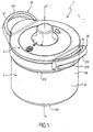
- the pressure cooker 1 according to the invention is intended to ensure the cooking of different foods under pressure in a domestic context. It therefore forms a domestic pressure cooker.
- the pressure cooker 1 according to the invention is therefore a kitchen utensil having a portable character (that is to say manually movable) and independent.
- the pressure cooker 1 is a thermally passive kettle, designed to increase pressure under the effect of a heating source which is external to it, such as a hob.
- the pressure cooker 1 comprises a vessel 2 forming a cooking vessel and advantageously having substantially a symmetry of revolution along an axis X-X '.
- the adjective " axial " will refer to the direction of this axis of symmetry X-X 'direction which is similar to the vertical direction when the device is in normal operation.
- the tank 2 is for example and conventionally manufactured by stamping a blank of a metallic material such as aluminum or stainless steel.
- the pressure cooker 1 also comprises a lid 3 intended to be attached to said tank 2 to form with it a cooking chamber preferably substantially sealed, that is to say sufficiently hermetic to allow a rise in pressure within it.
- the enclosure formed by the combination of the tank 2 and the lid 3 is designed to allow a significant increase in pressure within it, so that during cooking, the pressure in the chamber can be significantly greater than the atmospheric pressure, and for example exceed said atmospheric pressure of a value greater than or equal to 10 kPa, and preferably greater than or equal to 20 kPa. It is also quite possible, in order to allow a very fast and efficient cooking, that the chamber is designed so that the pressure prevailing within it can exceed the atmospheric pressure by a value substantially between 40 and 110 kPa, and preferably substantially between 50 and 100 kPa.
- the lid 3 preferably affects a general disc shape, complementary to the shape of the tank 2.
- the cover 3 can be locked or unlocked at will on the tank 2, the lid 3 of the lock allowing the enclosure to increase pressure without escaping the lid 3 under the effect of pressure.
- the pressure cooker 1 preferably comprises a locking / unlocking means 4 of the lid 3 on the tank 2.
- the locking / unlocking means 4 may be of any type known to those skilled in the art, and is conventionally likely to evolve between a lid 3 locking configuration relative to the tank 2 (illustrated in particular in the figure 3 ) in which the lid 3 is secured to the tank 2, and an unlocking configuration of the lid 3 relative to the tank 2 (illustrated in particular in FIG. figure 4 ), in which the lid 3 can be freely separated from the tank 2.
- the locking / unlocking means 4 comprises at least one locking element 5, 6 of the cover 3 relative to the tank 2, the said at least one locking element 5, 6 being movably mounted on the cover 2, substantially in radial translation with respect to the axis XX 'by means of at least one corresponding drive means between an indexed locking position (illustrated for example in FIG. figure 3 ) and an indexed unlocking position (illustrated for example in figure 4 ).
- said at least one locking element 5, 6 may comprise a jaw intended to grip the peripheral edges of the tank 2 and the lid 3.
- Said jaw may be in the form of a metal plate , U-shaped at its outer end, as is well known to those skilled in the art.
- the pressure cooker 1 comprises two locking elements 5, 6 constituted by bifurcated segments each having two respective locking bolts 5A, 5B, 6A, 6B, said segments being positioned opposite, diametrically opposite the general axis of symmetry XX 'of the apparatus.
- the drive means for each bifurcated segment consists of a respective driving arm, which carrying arm can for example come from material with the corresponding segment.
- Locking openings 50A, 50B, 60A, 60B complementary to the bolts 5A, 5B, 6A, 6B are formed in the tank 2, so that the locking of the lid 3 corresponds to the engagement of the bolts 5A, 5B, 6A, 6B in respective complementary openings 50A, 50B, 60A, 60B (cf. figure 3 ), in the manner of a bolt / strike lock system, to substantially prevent any movement of the cover 3 relative to the tank 2, while the unlocking of the cover 3 corresponds to the retraction and disengagement of the bolts 5A, 5B, 6A, 6B out of lights 50A, 50B, 60A, 60B corresponding so that said bolts do not cooperate with said lights 50A, 50B, 60A, 60B.
- the locking / unlocking means 4 of the cover 3 relative to the tank 2 is however not limited to a segment or jaw system and may for example be based on other principles, well known as such, of the average kind bayonet locking / unlocking or yoke locking / unlocking means.
- the pressure cooker 1 also comprises at least one gripping member 20 fixed on the tank 2, and preferably fixed directly on the wall of the tank 2.
- the gripping member 20 is designed to allow user to handle not only the tank 2 only but also and especially the pressure cooker 1 complete (formed of the assembly of the tank 2 and the lid 3), especially when said pressure cooker 1 is filled with cooked food or cooking possibly accompanied by a cooking liquid.
- the gripping member 20 is therefore designed to allow easy and firm manual gripping of the pressure cooker 1, so that the user can move manually and at will his pressure cooker 1 without risk of the latter escape him.
- the gripping member 20 comprises at least one handle 21 extending substantially from and towards the outside of the tank 2, radially with respect to the axis X-X '.
- the gripping member 20 is fixed on the tank 2 by means of a fastening means 20A making it possible to establish a mechanical connection, and preferably a mechanical connection, between the gripping member 20 and the tank 2.
- a fastening means 20A making it possible to establish a mechanical connection, and preferably a mechanical connection, between the gripping member 20 and the tank 2.
- the gripping member 20 is distinct and independent of the tank 2, and is attached and fixed on the latter, using the fastening means 20A.
- the attachment means 20A thus makes it possible to secure, that is to say to fix the gripping member 20 directly on the tank 2.
- the attachment means 20A comprises at least one attachment hole 200A passing through the wall of the tank 2, that is to say extending through the entire thickness E of said vessel wall.
- the fixing hole 200A is, according to the invention, positioned on the wall of the tank 2 to not communicate with the inside of the cooking chamber. This means that if the fixing hole 200A is provided through the wall of the tank 2 so as to completely cross the latter, it is located at a location of the tank wall 2 which does not contribute to forming, with the lid 3, the sealed cooking chamber.
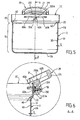
- the attachment means 20A also comprises a fastening element 201A, connected to the gripping member 20 and extending through the fixing hole 200A, to ensure the fastening of the fastener member. gripping 20 to the wall of the tank 2.
- the fastening element 201A is thus threaded into the fixing hole 200A, so as to pass through the wall of the tank over the entire thickness E of the latter.
- the fastening element 201A extends, through the fixing orifice 200A, between an outer end 202A secured to the gripping member 20 and an inner end 203A provided with a head abutting against the tank 2, around the orifice 200A, as shown in the figures.
- the invention is therefore based on a principle of very simple attachment of the gripping member 20 to the wall of the vessel 2, this fastening principle being based on the cooperation of a hole passing through the vessel wall from one side to the other. a fastening element passing through said hole.
- the invention provides for positioning the fixing orifice 200A in a zone of the tank wall 2 which does not contribute directly to forming the cooking chamber, so that any sealing problem is therefore discarded.
- the invention makes it possible to obtain a fixing of the gripping member 20 to the tank 2 by the simple implementation of a fixing orifice made directly in and through the wall of the tank 2 (and not through an adjoining room attached to the tank), while ensuring a durable seal of the cooking chamber.
- the fixing orifice 20A is formed through the side wall 2B of the tank 2, said orifice 200A extending through the entire thickness E of the side wall 2B, between the internal face 30 of the side wall 2B , facing the inside of the tank 2, and the outer face 31 of said side wall 2B, opposite the inner face 30 and located towards the outside of the pressure cooker 1.
- the pressure cooker 1 comprises two handles 21, 22 disposed on the tank 2 diametrically opposite to the axis of symmetry X-X '.
- the two handles 21, 22 are preferably identical, and each comprise for example a base 210, 220 fixed directly to the tank wall 2 and from which extends a loop 211, 221 which comes from material with the base and is intended to be entered manually by the user. More specifically, in the example illustrated in the figures, each handle 21, 22 is attached directly against the outer face 31 of the side wall 2B of the vessel 2.
- Each handle 21, 22 is preferably attached to the vessel 2 of the same way, that is to say by means of a corresponding fastening means comprising a fixing hole and a fastening element according to the foregoing description.
- the fastening element 201A comprises at least one screw 40 provided with a head 40A and a threaded rod 40B extending from said head 40A through the fixing orifice 200A.
- the gripping member 20 is advantageously provided with a threaded hole 50 in which is screwed the threaded rod 40B, the head 40A (whose diameter is greater than that of the rod 40B) being positioned inside the the tank 2 and bearing against the latter, that is to say against the inner face 30 of the side wall 2B.
- the tapped hole 50 which is for example made in the base 220 of the handle 22, is blind.
- the tapped hole 50 does not open towards the outside of the apparatus, so that once the handle 22 is assembled on the tank 2, the attachment means 20A is completely hidden and inaccessible to the
- the threaded rod 40B is entirely enclosed in the handle 22, which is preferably made of thermally insulating material, so as to provide complete thermal insulation to the user.
- each handle 21, 22 is in the form of an integral part made of a thermosetting material, obtained for example by molding, it being understood that any other material satisfying the thermal stresses can be envisaged (metallic material by example).
- the tapped hole 50 is preferably formed directly in the material constituting the base 220, by any known machining technique. However, it is quite possible to provide, according to an alternative solution, the threaded hole 50 is made in an insert, for example metal, said insert being itself integrated in the base 220 for example by screwing or overmolding.
- the lid 3 is designed to dock the side wall 2B of the tank 2 in a substantially sealed interface zone 60 to form the cooking chamber.
- the cooking chamber is thus delimited by the bottom 2A, the cover 3, the interface zone 60 and the portion 70 of the lateral wall extending between the bottom 2A and the interface zone 60.
- 200A is provided outside this portion 70.
- the orifice of 200A attachment is for example formed in a portion 80 of the side wall extending from the portion 70 contributing to delimit the enclosure, said portion 80 extending from the portion 70 to the upper opening 2C .
- the cooking chamber extends, in the vertical direction defined by the axis X-X ', between the bottom 2A and a sealing line corresponding to the interface zone between the cover 3 and the tank 2, the fixing orifice 200A being formed in the wall of the tank 2 outside the zone delimited between the bottom 2A and the interface zone 60.
- the fixing orifice 200A is provided on the tank wall 2, at an altitude greater than that of the interface zone 60 forming a sealing line (with respect to a reference frame whose origin corresponds for example to the bottom 2A).
- the cover 3 comprises a falling edge 3B, extending substantially downwardly from a main body 3A itself intended to be parallel to the bottom 2A.
- the falling edge 3B is intended to be introduced into the tank 2, inside the latter, to come into sealing contact with the inner face 30 of the side wall 2B.
- the falling edge 3B is provided with a seal 3C through which the sealing contact is made between the tank 2 and the lid 3.
- the latter has a recess 2D against which bears the seal 3C.
- the recess 2D is a substantially frustoconical portion of the side wall 2B which connects two other portions of said side wall 2B, these two other portions being each substantially vertical but of different diameters.
- the tank 2 thus flares from the bottom 2A.
Landscapes
- Engineering & Computer Science (AREA)
- Food Science & Technology (AREA)
- Cookers (AREA)
- General Preparation And Processing Of Foods (AREA)
- Commercial Cooking Devices (AREA)
- Basic Packing Technique (AREA)
Claims (10)
- Häuslicher Schnellkopftopf (1), aufweisend:- einen Topf (2), der eine Wand aufweist;- einen Deckel (3), der auf den Topf (2) aufzusetzen ist, um mit diesem einen im Wesentlichen dichten Kochraum zu bilden,- mindestens ein Greifelement (20), das mit Hilfe einer Befestigungseinrichtung (20A) an dem Topf (2) befestigt ist, dadurch gekennzeichnet, dass die Befestigungseinrichtung (20A) mindestens aufweist:- eine durch die Wand des Topfs (2) hindurchgehende Befestigungsöffnung (200A), wobei die Befestigungsöffnung (200A) so an der Wand des Topfs (2) angeordnet ist, um nicht mit dem Inneren des Kochraums in Verbindung zu stehen,- und ein Befestigungselement (201A), das mit dem Greifelement (20) verbunden ist und sich durch die Befestigungsöffnung (200A) erstreckt.
- Schnellkopftopf (1) nach Anspruch 1, dadurch gekennzeichnet, dass die Wand des Topfs (2) selbst einen Boden (2A) und eine Seitenwand (2B) aufweist, die sich von dem Umfang des Bodens (2A) aus aufwärts erstreckt, wobei sich die Befestigungsöffnung (200A) durch die Seitenwand (2B) hindurch erstreckt.
- Schnellkopftopf (1) nach Anspruch 2, dadurch gekennzeichnet, dass der Deckel (3) konzipiert ist, um an der Seitenwand des Topfs (2) längs einer im Wesentlichen dichten Grenzflächenzone (60) anzuliegen, um den Kochraum zu bilden, wobei der Kochraum von dem Boden (2A), dem Deckel (3), der Grenzflächenzone (60) und dem Teil (70) der Seitenwand (2B) begrenzt wird, der sich zwischen dem Boden (2A) und der Grenzflächenzone (60) erstreckt, wobei die Befestigungsöffnung (200A) außerhalb dieses Abschnitts (70) angeordnet ist.
- Schnellkopftopf (1) nach einem der Ansprüche 2 oder 3, dadurch gekennzeichnet, dass die Seitenwand (2B) eine zum Inneren des Topfs (2) hin gelegene Innenfläche (30) und eine gegenüberliegende Außenfläche (31) aufweist, wobei der Deckel (3) einen herabhängenden Rand (3B) aufweist, der in den Topf (2) einzuführen ist, um in dichten Kontakt mit der Innenfläche (30) der Seitenwand (2B) zu kommen.
- Schnellkopftopf (1) nach Anspruch 4, dadurch gekennzeichnet, dass der herabhängende Rand (3B) mit einer Dichtung (3C) versehen ist, mittels welcher der dichte Kontakt zwischen dem Topf (2) und dem Deckel (3) hergestellt ist.
- Schnellkopftopf (1) nach einem der Ansprüche 1 bis 5, dadurch gekennzeichnet, dass das Greifelement (20) mindestens einen Griff (21) aufweist, der sich im Wesentlichen ausgehend von und zu der Außenseite des Topfs (2) hin erstreckt.
- Schnellkopftopf (1) nach einem der Ansprüche 1 bis 6, dadurch gekennzeichnet, dass sich das Befestigungselement (201A) durch die Befestigungsöffnung (200A) hindurch zwischen einem an dem Greifelement (20) angebrachten äußeren Ende (202A) und einem inneren Ende (203A) erstreckt, das mit einem Kopf versehen ist, der an dem Topf (2) zur Anlage kommt.
- Schnellkopftopf (1) nach einem der Ansprüche 1 bis 7, dadurch gekennzeichnet, dass das Befestigungselement (201A) mindestens eine Schraube (40) aufweist, die mit einem Kopf (40A) und einem Gewindeschaft (40B) versehen ist, der sich von dem Kopf (40A) aus durch die Befestigungsöffnung (200A) hindurch erstreckt, wobei das Greifelement (20) mit einer Gewindebohrung (50) versehen ist, in welche der Gewindeschaft (40b) eingeschraubt ist, wobei der Kopf (40A) im Inneren des Topfs (2) positioniert ist und an diesem zur Anlage kommt.
- Schnellkopftopf (1) nach Anspruch 8, dadurch gekennzeichnet, dass die Gewindebohrung (50) blind ist.
- Schnellkopftopf (1) nach einem der Ansprüche 1 bis 9, dadurch gekennzeichnet, dass das Greifelement (20) direkt an der Wand des Topfs (2) befestigt ist.
Applications Claiming Priority (1)
| Application Number | Priority Date | Filing Date | Title |
|---|---|---|---|
| FR0705261A FR2918865B1 (fr) | 2007-07-20 | 2007-07-20 | Autocuiseur pourvu d'un organe de prehension fixe sur la cuve |
Publications (2)
| Publication Number | Publication Date |
|---|---|
| EP2016878A1 EP2016878A1 (de) | 2009-01-21 |
| EP2016878B1 true EP2016878B1 (de) | 2010-08-11 |
Family
ID=39345573
Family Applications (1)
| Application Number | Title | Priority Date | Filing Date |
|---|---|---|---|
| EP08447035A Not-in-force EP2016878B1 (de) | 2007-07-20 | 2008-07-22 | Schnellkochtopf mit einem festen Griff am Topf |
Country Status (8)
| Country | Link |
|---|---|
| US (1) | US8096440B2 (de) |
| EP (1) | EP2016878B1 (de) |
| JP (1) | JP2009082693A (de) |
| CN (1) | CN101352315B (de) |
| AT (1) | ATE476903T1 (de) |
| DE (1) | DE602008002111D1 (de) |
| ES (1) | ES2353787T3 (de) |
| FR (1) | FR2918865B1 (de) |
Families Citing this family (24)
| Publication number | Priority date | Publication date | Assignee | Title |
|---|---|---|---|---|
| CN1964653B (zh) * | 2004-06-08 | 2010-11-03 | Seb公司 | 气流烹调器具 |
| FR2871042B1 (fr) * | 2004-06-08 | 2006-12-22 | Seb Sa | Friteuse a enduction automatique de matiere grasse |
| CN201022639Y (zh) * | 2007-03-16 | 2008-02-20 | 厦门灿坤实业股份有限公司 | 烤盘把手 |
| DE202009015975U1 (de) | 2009-11-17 | 2010-03-11 | Hidde, Axel R., Dr. | Gargefäss mit Deckelmodul und Topfmodul |
| CN101828878B (zh) * | 2010-05-07 | 2012-01-11 | 武汉苏泊尔压力锅有限公司 | 能够旋转的炊具手柄 |
| DE202010012194U1 (de) * | 2010-07-05 | 2010-11-25 | Silag Handel Ag | Deckel für einen Schnellkochtopf sowie Schnellkochtopf mit einem Deckel |
| FR2974993B1 (fr) * | 2011-05-13 | 2014-04-11 | Seb Sa | Recipient de chauffe pour le chauffage d'aliments et appareil transportable comprenant un tel recipient de chauffe |
| US8827098B2 (en) * | 2011-09-23 | 2014-09-09 | Daniel Glanz | Collapsible lid handle for cookware |
| US8991226B2 (en) * | 2012-01-19 | 2015-03-31 | Ron R. Daniels | Storm grate lock device and method of use |
| US9538882B2 (en) | 2012-09-24 | 2017-01-10 | Becky Parr | Bakeware with covered rim |
| CN104433776B (zh) * | 2013-09-23 | 2017-06-20 | 珠海格力电器股份有限公司 | 电压力锅的连接结构和电压力锅 |
| CA2884817C (en) | 2014-03-13 | 2017-02-07 | Jamal F. Hammad | Slow cooking appliance with cammed lid latching arrangement |
| USD736576S1 (en) | 2014-04-23 | 2015-08-18 | Becky Parr | Knife |
| CN109996476A (zh) | 2017-08-09 | 2019-07-09 | 沙克忍者运营有限责任公司 | 烹饪装置及其部件 |
| USD914436S1 (en) | 2018-06-19 | 2021-03-30 | Sharkninja Operating Llc | Air diffuser with food preparation pot |
| USD883014S1 (en) | 2018-08-09 | 2020-05-05 | Sharkninja Operating Llc | Food preparation device |
| USD903413S1 (en) | 2018-08-09 | 2020-12-01 | Sharkninja Operating Llc | Cooking basket |
| USD934027S1 (en) | 2018-08-09 | 2021-10-26 | Sharkninja Operating Llc | Reversible cooking rack |
| USD883015S1 (en) | 2018-08-09 | 2020-05-05 | Sharkninja Operating Llc | Food preparation device and parts thereof |
| US20190254476A1 (en) | 2019-02-25 | 2019-08-22 | Sharkninja Operating Llc | Cooking device and components thereof |
| US11751710B2 (en) | 2019-02-25 | 2023-09-12 | Sharkninja Operating Llc | Guard for cooking system |
| USD918654S1 (en) | 2019-06-06 | 2021-05-11 | Sharkninja Operating Llc | Grill plate |
| USD982375S1 (en) | 2019-06-06 | 2023-04-04 | Sharkninja Operating Llc | Food preparation device |
| US11647861B2 (en) | 2020-03-30 | 2023-05-16 | Sharkninja Operating Llc | Cooking device and components thereof |
Family Cites Families (13)
| Publication number | Priority date | Publication date | Assignee | Title |
|---|---|---|---|---|
| JPS5633461Y2 (de) * | 1976-06-24 | 1981-08-08 | ||
| JPS594581Y2 (ja) * | 1981-06-05 | 1984-02-10 | 象印マホービン株式会社 | 圧力鍋 |
| JPS5812319U (ja) * | 1981-07-13 | 1983-01-26 | 東京ペット株式会社 | 折りたたみ式バスケツト |
| CN87209583U (zh) * | 1987-06-22 | 1988-09-28 | 李济群 | 安全多功能压力锅 |
| US5735194A (en) * | 1997-01-03 | 1998-04-07 | Cochran; David M. | Apparatus for separating chaff and roasting coffee and cocoa beans |
| US6125842A (en) * | 1999-05-11 | 2000-10-03 | Dennis G. Loyd Trust | Overflow pan assembly with splashguard cap and cap positioning means |
| FR2802400B1 (fr) * | 1999-12-15 | 2002-07-12 | Seb Sa | Appareil de cuisson sous pression a poignees amovibles |
| JP3533193B2 (ja) * | 2001-05-14 | 2004-05-31 | 株式会社よこやま | 鍋 |
| FR2862853B1 (fr) * | 2003-11-27 | 2006-09-15 | Seb Sa | Appareil de cuisson sous pression muni d'un dispositif de securite a la surpression, et joint d'etancheite pour un tel appareil |
| FR2862854B1 (fr) * | 2003-11-27 | 2006-09-15 | Seb Sa | Recipient de cuisson sous pression pourvu d'un couvercle rentrant a deformation controlee et couvercle correspondant |
| CN1751635A (zh) * | 2005-10-26 | 2006-03-29 | 张敬胜 | 发热内胆式微波锅 |
| ITMI20070697A1 (it) * | 2007-04-04 | 2008-10-05 | Ballarini Paolo & Figli Spa | Manico per una padella o un contenitore da cucina simile |
| USD612193S1 (en) * | 2009-10-13 | 2010-03-23 | Dion Darling | High speed, spill-proof cooking container |
-
2007
- 2007-07-20 FR FR0705261A patent/FR2918865B1/fr not_active Expired - Fee Related
-
2008
- 2008-07-17 US US12/174,946 patent/US8096440B2/en not_active Expired - Fee Related
- 2008-07-18 JP JP2008187488A patent/JP2009082693A/ja active Pending
- 2008-07-21 CN CN2008101358992A patent/CN101352315B/zh not_active Expired - Fee Related
- 2008-07-22 ES ES08447035T patent/ES2353787T3/es active Active
- 2008-07-22 DE DE602008002111T patent/DE602008002111D1/de active Active
- 2008-07-22 AT AT08447035T patent/ATE476903T1/de not_active IP Right Cessation
- 2008-07-22 EP EP08447035A patent/EP2016878B1/de not_active Not-in-force
Also Published As
| Publication number | Publication date |
|---|---|
| FR2918865B1 (fr) | 2009-10-09 |
| CN101352315B (zh) | 2013-06-12 |
| JP2009082693A (ja) | 2009-04-23 |
| EP2016878A1 (de) | 2009-01-21 |
| FR2918865A1 (fr) | 2009-01-23 |
| US8096440B2 (en) | 2012-01-17 |
| DE602008002111D1 (de) | 2010-09-23 |
| US20090020538A1 (en) | 2009-01-22 |
| CN101352315A (zh) | 2009-01-28 |
| ES2353787T3 (es) | 2011-03-07 |
| ATE476903T1 (de) | 2010-08-15 |
Similar Documents
| Publication | Publication Date | Title |
|---|---|---|
| EP2016878B1 (de) | Schnellkochtopf mit einem festen Griff am Topf | |
| EP2016875B1 (de) | Schnellkochtopf mit Abdeckungsschirm | |
| EP2016876B1 (de) | Schnellkochtopf mit Plastikverkleidung | |
| EP1535553B1 (de) | Druckgargerät mit einzelner Entspannungs- und Verriegelungsvorrichtung | |
| EP2926697B1 (de) | Druckkochgerät zum kochen von lebensmitteln mit umgekehrten bajonettverschlüssen, und entsprechende herstellungsmethode | |
| EP2052653B1 (de) | Schnellkochtopf mit einem Überdruck-Sicherheitssystem | |
| EP2340751B1 (de) | Gerät mit vereinfachter Handhabung | |
| FR2918862A1 (fr) | Autocuiseur pourvu d'une fenetre d'information | |
| EP3184007B1 (de) | Verstärkter schnellkochtopf | |
| EP3586689B1 (de) | Schnellkochtopf mit einem anschlag für den deckel | |
| EP1032296B1 (de) | Druckkochgerät mit mitteln zum unterstützen eines kochbehälters in einer erhöhten position | |
| EP1720433B1 (de) | Haushaltsdampfkochvorrichtung mit verbesserter führung für die verriegelungsmittel | |
| EP2716188B1 (de) | Druckkochgerät für Lebensmittel mit leichterem Deckel | |
| EP3262996B1 (de) | Deckel eines kochbehälters mit ausgiesselement | |
| EP2702907B1 (de) | Deckel für Dampfdruckkochtopf mit vereinfachter Konstruktion und Dampfdruckkochtopf mit solchem Deckel. | |
| FR3002426A1 (fr) | Couvercle de cuve pour robot de cuisine multifonctions | |
| EP3300640B1 (de) | Untereinheit eines deckels, schnellkochtopf, der mit einer solchen untereinheit ausgestattet ist, und entsprechendes herstellungsverfahren | |
| FR2860964A3 (fr) | Cuiseur electrique de securite | |
| FR3113574A3 (fr) | récipient pour cuire un aliment muni d'un dispositif de signalisation thermique |
Legal Events
| Date | Code | Title | Description |
|---|---|---|---|
| PUAI | Public reference made under article 153(3) epc to a published international application that has entered the european phase |
Free format text: ORIGINAL CODE: 0009012 |
|
| AK | Designated contracting states |
Kind code of ref document: A1 Designated state(s): AT BE BG CH CY CZ DE DK EE ES FI FR GB GR HR HU IE IS IT LI LT LU LV MC MT NL NO PL PT RO SE SI SK TR |
|
| AX | Request for extension of the european patent |
Extension state: AL BA MK RS |
|
| 17P | Request for examination filed |
Effective date: 20090715 |
|
| AKX | Designation fees paid |
Designated state(s): AT BE BG CH CY CZ DE DK EE ES FI FR GB GR HR HU IE IS IT LI LT LU LV MC MT NL NO PL PT RO SE SI SK TR |
|
| GRAP | Despatch of communication of intention to grant a patent |
Free format text: ORIGINAL CODE: EPIDOSNIGR1 |
|
| GRAS | Grant fee paid |
Free format text: ORIGINAL CODE: EPIDOSNIGR3 |
|
| GRAA | (expected) grant |
Free format text: ORIGINAL CODE: 0009210 |
|
| AK | Designated contracting states |
Kind code of ref document: B1 Designated state(s): AT BE BG CH CY CZ DE DK EE ES FI FR GB GR HR HU IE IS IT LI LT LU LV MC MT NL NO PL PT RO SE SI SK TR |
|
| REG | Reference to a national code |
Ref country code: GB Ref legal event code: FG4D Free format text: NOT ENGLISH |
|
| REG | Reference to a national code |
Ref country code: CH Ref legal event code: EP |
|
| REG | Reference to a national code |
Ref country code: IE Ref legal event code: FG4D Free format text: LANGUAGE OF EP DOCUMENT: FRENCH |
|
| REF | Corresponds to: |
Ref document number: 602008002111 Country of ref document: DE Date of ref document: 20100923 Kind code of ref document: P |
|
| REG | Reference to a national code |
Ref country code: NL Ref legal event code: VDEP Effective date: 20100811 |
|
| LTIE | Lt: invalidation of european patent or patent extension |
Effective date: 20100811 |
|
| PG25 | Lapsed in a contracting state [announced via postgrant information from national office to epo] |
Ref country code: FI Free format text: LAPSE BECAUSE OF FAILURE TO SUBMIT A TRANSLATION OF THE DESCRIPTION OR TO PAY THE FEE WITHIN THE PRESCRIBED TIME-LIMIT Effective date: 20100811 Ref country code: NL Free format text: LAPSE BECAUSE OF FAILURE TO SUBMIT A TRANSLATION OF THE DESCRIPTION OR TO PAY THE FEE WITHIN THE PRESCRIBED TIME-LIMIT Effective date: 20100811 Ref country code: NO Free format text: LAPSE BECAUSE OF FAILURE TO SUBMIT A TRANSLATION OF THE DESCRIPTION OR TO PAY THE FEE WITHIN THE PRESCRIBED TIME-LIMIT Effective date: 20101111 Ref country code: AT Free format text: LAPSE BECAUSE OF FAILURE TO SUBMIT A TRANSLATION OF THE DESCRIPTION OR TO PAY THE FEE WITHIN THE PRESCRIBED TIME-LIMIT Effective date: 20100811 Ref country code: LT Free format text: LAPSE BECAUSE OF FAILURE TO SUBMIT A TRANSLATION OF THE DESCRIPTION OR TO PAY THE FEE WITHIN THE PRESCRIBED TIME-LIMIT Effective date: 20100811 |
|
| PG25 | Lapsed in a contracting state [announced via postgrant information from national office to epo] |
Ref country code: BG Free format text: LAPSE BECAUSE OF FAILURE TO SUBMIT A TRANSLATION OF THE DESCRIPTION OR TO PAY THE FEE WITHIN THE PRESCRIBED TIME-LIMIT Effective date: 20101111 Ref country code: HR Free format text: LAPSE BECAUSE OF FAILURE TO SUBMIT A TRANSLATION OF THE DESCRIPTION OR TO PAY THE FEE WITHIN THE PRESCRIBED TIME-LIMIT Effective date: 20100811 Ref country code: IS Free format text: LAPSE BECAUSE OF FAILURE TO SUBMIT A TRANSLATION OF THE DESCRIPTION OR TO PAY THE FEE WITHIN THE PRESCRIBED TIME-LIMIT Effective date: 20101211 Ref country code: SI Free format text: LAPSE BECAUSE OF FAILURE TO SUBMIT A TRANSLATION OF THE DESCRIPTION OR TO PAY THE FEE WITHIN THE PRESCRIBED TIME-LIMIT Effective date: 20100811 Ref country code: PL Free format text: LAPSE BECAUSE OF FAILURE TO SUBMIT A TRANSLATION OF THE DESCRIPTION OR TO PAY THE FEE WITHIN THE PRESCRIBED TIME-LIMIT Effective date: 20100811 Ref country code: CY Free format text: LAPSE BECAUSE OF FAILURE TO SUBMIT A TRANSLATION OF THE DESCRIPTION OR TO PAY THE FEE WITHIN THE PRESCRIBED TIME-LIMIT Effective date: 20100811 |
|
| REG | Reference to a national code |
Ref country code: ES Ref legal event code: FG2A Effective date: 20110223 |
|
| REG | Reference to a national code |
Ref country code: IE Ref legal event code: FD4D |
|
| PG25 | Lapsed in a contracting state [announced via postgrant information from national office to epo] |
Ref country code: GR Free format text: LAPSE BECAUSE OF FAILURE TO SUBMIT A TRANSLATION OF THE DESCRIPTION OR TO PAY THE FEE WITHIN THE PRESCRIBED TIME-LIMIT Effective date: 20101112 Ref country code: SE Free format text: LAPSE BECAUSE OF FAILURE TO SUBMIT A TRANSLATION OF THE DESCRIPTION OR TO PAY THE FEE WITHIN THE PRESCRIBED TIME-LIMIT Effective date: 20100811 Ref country code: LV Free format text: LAPSE BECAUSE OF FAILURE TO SUBMIT A TRANSLATION OF THE DESCRIPTION OR TO PAY THE FEE WITHIN THE PRESCRIBED TIME-LIMIT Effective date: 20100811 |
|
| PG25 | Lapsed in a contracting state [announced via postgrant information from national office to epo] |
Ref country code: IE Free format text: LAPSE BECAUSE OF FAILURE TO SUBMIT A TRANSLATION OF THE DESCRIPTION OR TO PAY THE FEE WITHIN THE PRESCRIBED TIME-LIMIT Effective date: 20100811 Ref country code: DK Free format text: LAPSE BECAUSE OF FAILURE TO SUBMIT A TRANSLATION OF THE DESCRIPTION OR TO PAY THE FEE WITHIN THE PRESCRIBED TIME-LIMIT Effective date: 20100811 |
|
| PG25 | Lapsed in a contracting state [announced via postgrant information from national office to epo] |
Ref country code: SK Free format text: LAPSE BECAUSE OF FAILURE TO SUBMIT A TRANSLATION OF THE DESCRIPTION OR TO PAY THE FEE WITHIN THE PRESCRIBED TIME-LIMIT Effective date: 20100811 Ref country code: CZ Free format text: LAPSE BECAUSE OF FAILURE TO SUBMIT A TRANSLATION OF THE DESCRIPTION OR TO PAY THE FEE WITHIN THE PRESCRIBED TIME-LIMIT Effective date: 20100811 Ref country code: RO Free format text: LAPSE BECAUSE OF FAILURE TO SUBMIT A TRANSLATION OF THE DESCRIPTION OR TO PAY THE FEE WITHIN THE PRESCRIBED TIME-LIMIT Effective date: 20100811 Ref country code: EE Free format text: LAPSE BECAUSE OF FAILURE TO SUBMIT A TRANSLATION OF THE DESCRIPTION OR TO PAY THE FEE WITHIN THE PRESCRIBED TIME-LIMIT Effective date: 20100811 |
|
| PLBE | No opposition filed within time limit |
Free format text: ORIGINAL CODE: 0009261 |
|
| STAA | Information on the status of an ep patent application or granted ep patent |
Free format text: STATUS: NO OPPOSITION FILED WITHIN TIME LIMIT |
|
| 26N | No opposition filed |
Effective date: 20110512 |
|
| REG | Reference to a national code |
Ref country code: DE Ref legal event code: R097 Ref document number: 602008002111 Country of ref document: DE Effective date: 20110512 |
|
| PG25 | Lapsed in a contracting state [announced via postgrant information from national office to epo] |
Ref country code: MT Free format text: LAPSE BECAUSE OF FAILURE TO SUBMIT A TRANSLATION OF THE DESCRIPTION OR TO PAY THE FEE WITHIN THE PRESCRIBED TIME-LIMIT Effective date: 20100811 |
|
| BERE | Be: lapsed |
Owner name: SEB S.A. Effective date: 20110731 |
|
| PG25 | Lapsed in a contracting state [announced via postgrant information from national office to epo] |
Ref country code: MC Free format text: LAPSE BECAUSE OF NON-PAYMENT OF DUE FEES Effective date: 20110731 |
|
| PG25 | Lapsed in a contracting state [announced via postgrant information from national office to epo] |
Ref country code: BE Free format text: LAPSE BECAUSE OF NON-PAYMENT OF DUE FEES Effective date: 20110731 |
|
| REG | Reference to a national code |
Ref country code: CH Ref legal event code: PL |
|
| PG25 | Lapsed in a contracting state [announced via postgrant information from national office to epo] |
Ref country code: LI Free format text: LAPSE BECAUSE OF NON-PAYMENT OF DUE FEES Effective date: 20120731 Ref country code: CH Free format text: LAPSE BECAUSE OF NON-PAYMENT OF DUE FEES Effective date: 20120731 |
|
| PG25 | Lapsed in a contracting state [announced via postgrant information from national office to epo] |
Ref country code: LU Free format text: LAPSE BECAUSE OF NON-PAYMENT OF DUE FEES Effective date: 20110722 |
|
| PG25 | Lapsed in a contracting state [announced via postgrant information from national office to epo] |
Ref country code: HU Free format text: LAPSE BECAUSE OF FAILURE TO SUBMIT A TRANSLATION OF THE DESCRIPTION OR TO PAY THE FEE WITHIN THE PRESCRIBED TIME-LIMIT Effective date: 20100811 |
|
| PG25 | Lapsed in a contracting state [announced via postgrant information from national office to epo] |
Ref country code: PT Free format text: LAPSE BECAUSE OF FAILURE TO SUBMIT A TRANSLATION OF THE DESCRIPTION OR TO PAY THE FEE WITHIN THE PRESCRIBED TIME-LIMIT Effective date: 20100811 |
|
| REG | Reference to a national code |
Ref country code: FR Ref legal event code: PLFP Year of fee payment: 8 |
|
| PGFP | Annual fee paid to national office [announced via postgrant information from national office to epo] |
Ref country code: DE Payment date: 20150713 Year of fee payment: 8 Ref country code: ES Payment date: 20150731 Year of fee payment: 8 Ref country code: GB Payment date: 20150717 Year of fee payment: 8 |
|
| PGFP | Annual fee paid to national office [announced via postgrant information from national office to epo] |
Ref country code: FR Payment date: 20150731 Year of fee payment: 8 Ref country code: TR Payment date: 20150707 Year of fee payment: 8 |
|
| PGFP | Annual fee paid to national office [announced via postgrant information from national office to epo] |
Ref country code: IT Payment date: 20150710 Year of fee payment: 8 |
|
| REG | Reference to a national code |
Ref country code: DE Ref legal event code: R119 Ref document number: 602008002111 Country of ref document: DE |
|
| GBPC | Gb: european patent ceased through non-payment of renewal fee |
Effective date: 20160722 |
|
| PG25 | Lapsed in a contracting state [announced via postgrant information from national office to epo] |
Ref country code: DE Free format text: LAPSE BECAUSE OF NON-PAYMENT OF DUE FEES Effective date: 20170201 Ref country code: FR Free format text: LAPSE BECAUSE OF NON-PAYMENT OF DUE FEES Effective date: 20160801 |
|
| REG | Reference to a national code |
Ref country code: FR Ref legal event code: ST Effective date: 20170331 |
|
| PG25 | Lapsed in a contracting state [announced via postgrant information from national office to epo] |
Ref country code: GB Free format text: LAPSE BECAUSE OF NON-PAYMENT OF DUE FEES Effective date: 20160722 |
|
| PG25 | Lapsed in a contracting state [announced via postgrant information from national office to epo] |
Ref country code: IT Free format text: LAPSE BECAUSE OF NON-PAYMENT OF DUE FEES Effective date: 20160722 |
|
| PG25 | Lapsed in a contracting state [announced via postgrant information from national office to epo] |
Ref country code: ES Free format text: LAPSE BECAUSE OF NON-PAYMENT OF DUE FEES Effective date: 20160723 |
|
| REG | Reference to a national code |
Ref country code: ES Ref legal event code: FD2A Effective date: 20181130 |
|
| PG25 | Lapsed in a contracting state [announced via postgrant information from national office to epo] |
Ref country code: TR Free format text: LAPSE BECAUSE OF NON-PAYMENT OF DUE FEES Effective date: 20160722 |