EP2016875B1 - Pressure cooker equipped with a screen - Google Patents
Pressure cooker equipped with a screen Download PDFInfo
- Publication number
- EP2016875B1 EP2016875B1 EP08447038A EP08447038A EP2016875B1 EP 2016875 B1 EP2016875 B1 EP 2016875B1 EP 08447038 A EP08447038 A EP 08447038A EP 08447038 A EP08447038 A EP 08447038A EP 2016875 B1 EP2016875 B1 EP 2016875B1
- Authority
- EP
- European Patent Office
- Prior art keywords
- pressure cooker
- pan
- locking
- tank
- lid
- Prior art date
- Legal status (The legal status is an assumption and is not a legal conclusion. Google has not performed a legal analysis and makes no representation as to the accuracy of the status listed.)
- Not-in-force
Links
Images


Classifications
-
- A—HUMAN NECESSITIES
- A47—FURNITURE; DOMESTIC ARTICLES OR APPLIANCES; COFFEE MILLS; SPICE MILLS; SUCTION CLEANERS IN GENERAL
- A47J—KITCHEN EQUIPMENT; COFFEE MILLS; SPICE MILLS; APPARATUS FOR MAKING BEVERAGES
- A47J27/00—Cooking-vessels
- A47J27/08—Pressure-cookers; Lids or locking devices specially adapted therefor
- A47J27/0804—Locking devices
Definitions
- the present invention relates to the general technical field of cooking utensils of the type cooking vessels, and in particular to the sector of pressure cookers, that is to say cooking pots under pressure to ensure the cooking under pressure of steam contained in them.
- Domestic pressure cookers are well known. They usually consist of a metal bowl for food and a lid, also metal, to be reported and locked on the tank to form with the latter a sealed cooking chamber.
- Such a pressure cooker is intended to be subjected to the influence of a heating source (such as a cooking plate) so as to allow the rise in pressure and temperature of the enclosure and thus the cooking under pressure of the food contained in the latter.
- a heating source such as a cooking plate
- a pressure cooker representing the prior art is described for example in FR-2 865 621 A .
- the known pressure cookers are anxious, that is to say that they generate for many users or potential users a diffuse anxiety. Such a feeling is certainly generally unfounded, since these devices are generally very easy and safe to use. This feeling of fear is nevertheless present and it is likely to prevent many people from using the pressure cookers despite all the benefits, in terms of speed and quality of cooking in particular, that they provide.
- the objects assigned to the invention therefore aim to remedy the various disadvantages listed above and to propose a new solution.
- domestic pressure cooker whose construction is not anxious for the user.
- Another object of the invention is to propose a new domestic pressure cooker of particularly simple construction.
- Another object of the invention is to propose a new domestic pressure cooker of particularly compact and inexpensive construction.
- Another object of the invention is to propose a new domestic pressure cooker whose manufacture is very simple, fast and cheap.
- Another object of the invention is to propose a new domestic pressure cooker whose design uses a very limited number of different parts.
- Another object of the invention is to propose a new domestic pressure cooker whose general appearance is very close to that of a conventional pan.
- the pressure cooker 1 according to the invention is intended to ensure the cooking of different foods under pressure in a domestic context. It therefore forms a domestic pressure cooker.
- the pressure cooker 1 according to the invention is therefore a kitchen utensil having a character portable (that is to say, manually movable) and independent.
- the pressure cooker 1 is a thermally passive kettle, designed to increase pressure under the effect of a heating source which is external to it, such as a hob.
- the pressure cooker 1 comprises a vessel 2 forming a cooking vessel and advantageously having substantially a symmetry of revolution along an axis X-X '.
- the adjective " axial " will refer to the direction of this axis of symmetry X-X 'direction which is similar to the vertical direction when the device is in normal operation.
- the tank 2 is for example and conventionally manufactured by stamping a blank of a metallic material such as aluminum or stainless steel.
- the pressure cooker 1 also comprises a lid 3 intended to be attached to said tank 2 to form with it a cooking chamber preferably substantially sealed, that is to say sufficiently hermetic to allow a rise in pressure within it.
- the enclosure formed by the combination of the tank 2 and the lid 3 is designed to allow a significant increase in pressure within it, so that during cooking, the pressure in the chamber can be significantly greater than the atmospheric pressure, and for example exceed said atmospheric pressure of a value greater than or equal to 10 kPa, and preferably greater than or equal to 20 kPa. It is also quite possible, in order to allow a very fast and efficient cooking, that the chamber is designed so that the pressure prevailing within it can exceed the atmospheric pressure by a value substantially between 40 and 110 kPa, and preferably substantially between 50 and 100 kPa.
- the lid 3 preferably affects a general disc shape, complementary to the shape of the tank 2.
- the lid 3 can be locked or unlocked at will on the tank 2, the lid 3 of the lock allowing the enclosure to rise in pressure without escaping the lid 3 under the effect of pressure.
- the pressure cooker 1 preferably comprises a locking / unlocking means 4 of the lid 3 on the tank 2.
- the locking / unlocking means 4 is advantageously designed to move between a locking configuration of the lid 3 relative to the tank 2 (illustrated in particular in figure 3 ) in which the lid 3 is secured to the tank 2, and an unlocking configuration of the lid 3 relative to the tank 2 (illustrated in particular in FIG. figure 4 ), in which the lid 3 can be freely separated from the tank 2.
- the locking / unlocking means 4 comprises at least one locking opening 50A, 50B, 60A, 60B formed through the wall of the tank 2, that is to say through the wall of the tank. the tank over its entire thickness E.
- the pressure cooker 1 comprises four locking openings 50A, 50B, 60A, 60B preferentially arranged in the upper part 80 of the wall 2B of the tank 2, that is to say towards the upper opening 2C of the tank 2.
- said locking openings 50A, 50B, 60A, 60B are preferably grouped in pairs, said pairs being diametrically opposed.
- the locking / unlocking means 4 further comprises at least one bolt 5A, 5B, 6A, 6B movably mounted on the cover 3 between, on the one hand, a locking position of the cover 3 (illustrated in particular in FIG. the figure 3 ) in which the bolt 5A, 5B, 6A, 6B is engaged in the corresponding locking opening 50A, 50B, 60A, 60B to prevent any separation of the lid 3 of the tank 2, in the manner of a bolt lock system and strike, and on the other hand an unlocking position of the lid 3 (illustrated in FIG.
- the pressure cooker 1 comprises a number of bolts 5A, 5B, 6A, 6B corresponding to the number of locking openings 50A, 50B, 60A, 60B, that is to say that it comprises in this case four bolts 5A, 5B, 6A, 6B intended to cooperate respectively with the openings 50A, 50B, 60A, 60B.
- the bolts 5A, 5B, 6A, 6B are mounted movable in translation on the cover 3 between a retracted position (illustrated in FIG.
- FIG. figure 4 in which the bolts 5A, 5B, 6A, 6B are retracted inside the cover 3 so as not to protrude laterally from the latter, and on the other hand an extended position (illustrated in FIG. figure 3 ) in which each bolt 5A, 5B, 6A, 6B enters the respective opening 50A, 50B, 60A, 60B, the passage from the retracted position to the deployed position being effected by a displacement in translation in a direction substantially parallel to the main extension plane of the lid 3, which is preferably parallel to the bottom 2A of the tank 2.
- the locking / unlocking means 4 advantageously comprises two bifurcated segments 5, 6 positioned relative to one another diametrically opposite to the axis X-X ', each segment fork 5, 6 respectively forming the first pair of bolts 5A, 5B and the second pair of bolts 6A, 6B.
- each bifurcated segment is formed of an integral metal plate whose one end has a fork shape, each tooth of the fork corresponding to a bolt 5A, 5B, 6A, 6B.
- Each segment 5, 6 is mounted in radial translation in consideration of the axis X-X '.
- the locking / unlocking means 4 is manually controlled by the user.
- the pressure cooker 1 preferably comprises a control knob 7A mounted on the cover 3 to rotate along the axis X-X '.
- the knob 7A is mechanically connected to the segments 5, 6 so that the rotation of the knob 7A in one direction causes a radial retraction (centripetal) of the bolts 5A, 5B, 6A, 6B while the rotation of the knob 7A in the opposite direction generates inverse centrifugal radial displacement of the bolts 5A, 5B, 6A, 6B for engaging the latter in the corresponding locking openings 50A, 50B, 60A, 60B.
- the driving of the segments 5, 6 by the knob 7A can be achieved by any means known to those skilled in the art.
- the knob 7A can be integral with a plate in which are formed drive lights 70, the segments 5, 6 themselves being provided with respective pins 51 engaged in the drive lights 70.
- the rotation of the knob 7A causes the concomitant rotation of the driving lights 70 which, by a ramp effect and in combination with a translation guide of the segments 5, 6, transform their rotational movement into a radial translation movement of said segments 5, 6.
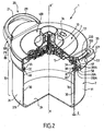
- the pressure cooker 1 further comprises a screen 100 fixed on the tank 2 (and preferably fixed on the side wall 2B of the tank 2) to mask said at least one locking opening 50A, 50B, 60A , 60B so that the latter is substantially not visible from outside the cooking chamber.
- the function of the screen 100 is to hide the openings 50A, 50B, 60A, 60B at the sight of the user when the pressure cooker 1 is closed, that is to say when the lid 3 is reported on the tank 2. From this way, the part of the locking system that is likely to be one of the most anxiety for the user, as well as its operating principle, are invisible to the user. This reduces the anxiety that could be felt by the user when using the pressure cooker 1. It also improves the reliability of the lock and the safety of the user, by preventing any object from can be inadvertently inserted into a locking opening, thus preventing the proper functioning of the device.
- the pressure cooker 1 comprises a cover 400 attached and fixed on the lid 3 to mask in particular the segments 5, 6 and their drive means (light 70, pin 51 ).
- the pressure cooker 1 comprises at least one gripping member 20 fixed on the tank 2, and preferably fixed directly on the wall of the tank 2.
- the gripping member 20 is designed to allow the user to manipulate only the tank 2 only but also and especially the pressure cooker 1 complete (formed of the assembly of the tank 2 and the lid 3), in particular when said pressure cooker 1 is filled with cooked or cooking food, possibly accompanied by a cooking liquid.
- the gripping member 20 is therefore designed to allow easy and firm manual gripping of the pressure cooker 1, so that the user can move manually and at will his pressure cooker 1 without the risk of the latter escape him.
- the gripping member 20 comprises at least one handle 21 fixed on the wall of the vessel 2, outside said vessel 2. Said handle 21 preferably extends substantially from and towards the outside of the vessel 2, radially with respect to the axis X-X '.
- the pressure cooker 1 comprises two handles 21, 22 arranged diametrically opposite one another with respect to the axis X-X ', said handles 21, 22 being extending radially from the side wall 2B of the tank 2, towards the outside thereof.
- the gripping member 20 is shaped and positioned on the tank 2 to form said screen 100.
- the gripping member 20 has a dual function since it allows on the one hand the manipulation of the pressure cooker 1 and on the other hand the masking of the locking openings 50A, 50B, 60A, 60B.
- Such a dual function is particularly interesting from the point of view of the simplicity of industrial manufacture and the associated costs.
- the two handles 21, 22 are identical, and each comprise for example a base 210, 220 fixed directly to the tank wall 2, against the outer face 31 of the latter. From each base 210, 220 extends a respective loop 211, 221 intended to be entered manually by the user.
- a portion of said bolt 5A, 5B, 6A, 6B protrudes out of the tank 2 through the corresponding locking opening 50A, 50B, 60A, 60B, that is to say that each bolt 5A, 5B, 6A, 6B completely through the respective opening 50A, 50B, 60A, 60B and spring on the other side of the tank 2, as illustrated in particular in FIGS. figures 3 and 5 .
- the screen 100 is provided with at least one blind internal housing opening on the corresponding locking opening 50A, 50B, 60A, 60B to accommodate within it said portion of the protruding bolt.
- each base 210, 220 advantageously has cavities 210A, 210B, 220A, 220B forming internal blind housings, said cavities being intended to be positioned opposite the openings 50A, 50B, 60A, 60B so as to form a housing for respectively receiving each bolt 5A, 5B, 6A, 6B when they are in the deployed position and project from the outer wall 31.
- the gripping member 20 is fixed on the tank 2 with the aid of at least one fastening means 20A making it possible to establish a mechanical connection, and preferably a mechanical connection, between the gripping member 20 and the tank 2.
- the gripping member 20 is distinct and independent of the tank 2, and is attached and fixed on the latter, using the fastening means 20A.
- the fastening means 20A thus makes it possible to secure, that is to say to fasten the gripper 20 directly on the tank 2.
- the attachment means 20A comprises at least one elongate fastener 201A extending from the wall of the tank 2 towards the outside of the tank 2.
- the attachment means 20A further comprises a fixing orifice 200A passing through the wall of the tank 2, that is to say extending through the entire thickness E of said tank wall 2.
- the fastener 201A preferably extends through said fixing hole 200A. The fastening element 201A is thus threaded into the fixing orifice 200A, so as to pass through the wall of the tank over the entire thickness E of the latter.
- the fastening element 201A extends, through the fixing orifice 200A, between an outer end 202A secured to the gripping member 20 and an inner end 203A provided with a head abutting against the tank 2, around the orifice 200A, as shown in the figures.
- Each handle 21, 22 is preferably attached to the tank 2 in the same way, that is to say by means of a corresponding fastening means comprising a fixing hole and a fastening element as described above.
- the fastening element 201A comprises at least one screw 40 provided with a head 40A and a threaded rod 40B extending from said head 40A through the fixing orifice 200A.
- the gripping member 20 is advantageously provided with a threaded hole 50 in which is screwed the threaded rod 40B, the head 40A (whose diameter is greater than that of the rod 40B) being positioned inside the the tank 2 and bearing against the latter, that is to say against the inner face 30 of the side wall 2A.
- each handle 21, 22 is thus fixed by means of a screw screwed into a threaded hole in the center of the base 210, 220 of each handle.
- the attachment means 20A comprises at least one holding member 300 which is integral with the gripping member 20 and inserted into the locking aperture 50A, 50B, 60A, 60B.
- the holding element 300 comprises lugs 301, 302 extending from each handle 21, 22.
- each handle 21, 22 is provided with two respective lugs 301, 302 which come from matter with the corresponding handle and are each fitly introduced into a corresponding locking opening 50A, 50B, 60A, 60B.
- the two lugs from the handle 21 are respectively engaged in the locking openings 60A, 60B to prevent the rotation of the handle 21 about the axis of the screw 40.
- the locking openings 50A, 50B, 60A , 60B have a substantially oblong shape and the holding member pins 300 are introduced to one end of these openings.
- each locking opening 50A, 50B, 60A, 60B ensures a double function since it allows on the one hand a locking of the lid 3 on the tank 2 by cooperation with the bolts 5A, 5B, 6A, 6B and other part it ensures a holding in position of the handles 21, 22 by cooperation with lugs (or any equivalent part) from said handles.
- the holding member 300 is only intended to prevent rotation of the handles about the axis of the fixing screw 40A, which provides most of the fixation.
- handles 21, 22 are, in a conventional manner, fixed on a metal bridge itself welded to the outer face of the side wall 2B.
Landscapes
- Engineering & Computer Science (AREA)
- Food Science & Technology (AREA)
- Cookers (AREA)
- General Preparation And Processing Of Foods (AREA)
- Separation, Recovery Or Treatment Of Waste Materials Containing Plastics (AREA)
Abstract
Description
La présente invention se rapporte au domaine technique général des ustensiles de cuisine du type récipients de cuisson, et en particulier au secteur des autocuiseurs, c'est-à-dire des marmites de cuisson sous pression destinées à assurer la cuisson sous pression de vapeur des aliments contenus en leur sein.The present invention relates to the general technical field of cooking utensils of the type cooking vessels, and in particular to the sector of pressure cookers, that is to say cooking pots under pressure to ensure the cooking under pressure of steam contained in them.
La présente invention concerne plus particulièrement un autocuiseur domestique comprenant au moins :
- une cuve qui comprend elle-même une paroi,
- un couvercle destiné à être rapporté sur la cuve pour former avec cette dernière une enceinte de cuisson,
- et un moyen de verrouillage / déverrouillage du couvercle sur la cuve.
- a tank which itself comprises a wall,
- a lid intended to be attached to the tank to form with the latter a cooking chamber,
- and means for locking / unlocking the lid on the tank.
Les autocuiseurs domestiques sont bien connus. Ils se composent habituellement d'une cuve métallique destinée à accueillir les aliments et d'un couvercle, métallique lui aussi, destiné à être rapporté et verrouillé sur la cuve pour former avec cette dernière une enceinte de cuisson étanche.Domestic pressure cookers are well known. They usually consist of a metal bowl for food and a lid, also metal, to be reported and locked on the tank to form with the latter a sealed cooking chamber.
Un tel autocuiseur est destiné à être soumis à l'influence d'une source de chauffe (comme par exemple une plaque de cuisson) de manière à permettre la montée en pression et en température de l'enceinte et ainsi la cuisson sous pression des aliments contenus dans cette dernière.Such a pressure cooker is intended to be subjected to the influence of a heating source (such as a cooking plate) so as to allow the rise in pressure and temperature of the enclosure and thus the cooking under pressure of the food contained in the latter.
Un autocuiseur représentant l'art antérieur est décrit par exemple dans
Il existe différents types de moyens de verrouillage / déverrouillage du couvercle sur la cuve, tel que notamment les systèmes à étriers, à baïonnettes ou à mâchoires, pour n'en citer que certains parmi les plus répandus.There are different types of locking / unlocking means of the lid on the tank, such as including stirrup systems, bayonets or jaws, to name only some of the most widespread.
Ces moyens de verrouillage / déverrouillage connus assurent généralement parfaitement, du point de vue de la sécurité en particulier, leur fonction d'assujettissement du couvercle à la cuve de manière à permettre à l'enceinte de cuisson ainsi créée de monter en pression de façon fiable et sûre.These known locking / unlocking means generally ensure, from the point of view of safety in particular, their function of securing the lid to the tank so as to allow the cooking chamber thus created to reliably increase pressure. and sure.
Ces moyens de verrouillage / déverrouillage connus présentent toutefois un aspect visuel très technique qui est de nature à effrayer de nombreux utilisateurs potentiels. Ces derniers, en particulier lorsqu'ils n'ont pas l'habitude de la cuisson sous pression, peuvent craindre en effet de ne pas savoir utiliser un appareil d'apparence aussi technique, qui leur paraît très éloigné des ustensiles traditionnels de cuisson, du genre casserole, dont ils ont l'habitude. La présence des moyens de verrouillage / déverrouillage est également de nature à rappeler, même de façon inconsciente, à ces utilisateurs potentiels, que les autocuiseurs fonctionnent à des niveaux élevés de pression et de température. Cela peut renforcer l'appréhension desdits utilisateurs et amener une certaine réticence de leur part à utiliser un autocuiseur, qui s'apparente plus pour eux à une sorte de machine complexe et dangereuse qu'à un ustensile culinaire domestique.These known locking / unlocking means, however, have a very technical visual appearance that is likely to frighten many potential users. The latter, especially when they are not used to cooking under pressure, may fear that they may not be able to use a device that looks so technical, which seems far removed from traditional cooking utensils. kind of pan, which they are used to. The presence of the locking / unlocking means is also likely to remind, even unconsciously, these potential users that the pressure cookers operate at high levels of pressure and temperature. This may reinforce the apprehension of these users and lead to some reluctance on their part to use a pressure cooker, which is more like a kind of complex and dangerous machine for them than a domestic cooking utensil.
En définitive, les autocuiseurs connus présentent un caractère anxiogène, c'est-à-dire qu'ils génèrent à l'endroit de nombreux utilisateurs ou utilisateurs potentiels une anxiété diffuse. Un tel sentiment est certes généralement infondé, puisque ces appareils sont généralement d'utilisation très facile et sûre. Ce sentiment de crainte est pourtant bien présent et il est susceptible d'empêcher de nombreuses personnes d'utiliser les autocuiseurs malgré tout le bénéfice, en matière de rapidité et de qualité de cuisson notamment, que ces derniers procurent.Ultimately, the known pressure cookers are anxious, that is to say that they generate for many users or potential users a diffuse anxiety. Such a feeling is certainly generally unfounded, since these devices are generally very easy and safe to use. This feeling of fear is nevertheless present and it is likely to prevent many people from using the pressure cookers despite all the benefits, in terms of speed and quality of cooking in particular, that they provide.
Les objets assignés à l'invention visent en conséquence à porter remède aux différents inconvénients énumérés précédemment et à proposer un nouvel autocuiseur domestique dont la construction n'est pas anxiogène pour l'utilisateur.The objects assigned to the invention therefore aim to remedy the various disadvantages listed above and to propose a new solution. domestic pressure cooker whose construction is not anxious for the user.
Un autre objet de l'invention vise à proposer un nouvel autocuiseur domestique de construction particulièrement simple.Another object of the invention is to propose a new domestic pressure cooker of particularly simple construction.
Un autre objet de l'invention vise à proposer un nouvel autocuiseur domestique de construction particulièrement compacte et bon marché.Another object of the invention is to propose a new domestic pressure cooker of particularly compact and inexpensive construction.
Un autre objet de l'invention vise à proposer un nouvel autocuiseur domestique dont la fabrication est très simple, rapide et bon marché.Another object of the invention is to propose a new domestic pressure cooker whose manufacture is very simple, fast and cheap.
Un autre objet de l'invention vise à proposer un nouvel autocuiseur domestique dont la conception met en oeuvre un nombre très limité de pièces différentes.Another object of the invention is to propose a new domestic pressure cooker whose design uses a very limited number of different parts.
Un autre objet de l'invention vise à proposer un nouvel autocuiseur domestique dont l'aspect général est très proche de celui d'une casserole classique.Another object of the invention is to propose a new domestic pressure cooker whose general appearance is very close to that of a conventional pan.
Les objets assignés à l'invention sont atteints à l'aide d'un autocuiseur domestique comprenant au moins :
- une cuve qui comprend elle-même une paroi,
- un couvercle destiné à être rapporté sur la cuve pour former avec cette dernière une enceinte de cuisson,
- un moyen de verrouillage / déverrouillage du couvercle sur la cuve, ledit autocuiseur étant caractérisé en ce que le moyen de verrouillage /déverrouillage comprend d'une part au moins une ouverture de verrouillage ménagée à travers la paroi de la cuve et d'autre part un pêne monté mobile sur le couvercle entre une position de verrouillage du couvercle dans laquelle le pêne est engagé dans l'ouverture de verrouillage et une position de déverrouillage du couvercle dans laquelle le pêne est dégagé de l'ouverture de verrouillage, ledit autocuiseur comprenant en outre un écran fixé sur la cuve pour masquer ladite ouverture de verrouillage de façon que cette dernière ne soit sensiblement pas visible de l'extérieur de l'enceinte de cuisson.
- a tank which itself comprises a wall,
- a lid intended to be attached to the tank to form with the latter a cooking chamber,
- a means for locking / unlocking the lid on the tank, said pressure cooker being characterized in that the locking / unlocking means comprises on the one hand at least one locking opening formed through the wall of the tank and on the other hand a bolt mounted movably on the cover between a locking position of the cover in which the bolt is engaged in the locking aperture and a release position of the cover in which the bolt is released from the locking aperture, said pressure cooker further comprising a screen attached to the tank to mask said locking aperture so as to that the latter is substantially not visible from outside the cooking chamber.
D'autres particularités et avantages de l'invention apparaîtront et ressortiront plus en détails à la lecture de la description faite ci-après, en référence aux dessins annexés, donnés à titre d'exemple illustratif et non limitatif dans lesquels :
- La
figure 1 illustre, selon une vue générale en perspective, un autocuiseur domestique conforme à l'invention. - La
figure 2 illustre, selon une vue générale en perspective partiellement coupée, selon deux plans de coupe sensiblement perpendiculaires, l'autocuiseur de lafigure 1 . - La
figure 3 illustre, selon une vue de dessus partiellement écorchée et coupée, l'autocuiseur desfigures 1 et2 avec le couvercle verrouillé sur la cuve. - La
figure 4 illustre, selon une vue de dessus partiellement écorchée et coupée, l'autocuiseur desfigures 1 à 3 avec son couvercle déverrouillé sur la cuve. - La
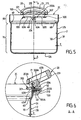
figure 5 illustre, selon une vue latérale en coupe, la cuve de l'autocuiseur illustré auxfigures 1 à 4 . - La
figure 6 illustre, selon une vue en coupe selon la ligne A-A de lafigure 5 , un détail agrandi de réalisation de la cuve illustrée à lafigure 5 . - La
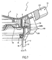
figure 7 illustre, selon une vue en perspective coupée, un détail de réalisation de d'autocuiseur illustré auxfigures 1 à 4 .
- The
figure 1 illustrates, in a general perspective view, a domestic pressure cooker according to the invention. - The
figure 2 illustrates, according to a general perspective view partially cut, according to two substantially perpendicular cutting planes, the pressure cooker of thefigure 1 . - The
figure 3 illustrates, according to a top view partially cut and cut, the pressure cooker offigures 1 and2 with the lid locked on the tank. - The
figure 4 illustrates, according to a top view partially cut and cut, the pressure cooker ofFigures 1 to 3 with its lid unlocked on the tank. - The
figure 5 illustrates, in a sectional side view, the tank of the pressure cooker illustrated in FIGS.Figures 1 to 4 . - The
figure 6 illustrates, according to a sectional view along the line AA of thefigure 5 , an enlarged detail of realization of the tank illustrated in thefigure 5 . - The
figure 7 illustrates, in a cut perspective view, a detail of production of pressure cooker illustrated in FIGS.Figures 1 to 4 .
L'autocuiseur 1 conforme à l'invention est destiné à assurer la cuisson de différents aliments sous pression dans un contexte domestique. Il forme donc à ce titre un autocuiseur domestique.The pressure cooker 1 according to the invention is intended to ensure the cooking of different foods under pressure in a domestic context. It therefore forms a domestic pressure cooker.
L'autocuiseur 1 conforme à l'invention est donc un ustensile de cuisine présentant un caractère portatif (c'est-à-dire déplaçable manuellement) et indépendant.The pressure cooker 1 according to the invention is therefore a kitchen utensil having a character portable (that is to say, manually movable) and independent.
Avantageusement, l'autocuiseur 1 conforme à l'invention constitue une marmite passive thermiquement, conçue pour monter en pression sous l'effet d'une source de chauffe qui lui est extérieure, telle qu'une plaque de cuisson.Advantageously, the pressure cooker 1 according to the invention is a thermally passive kettle, designed to increase pressure under the effect of a heating source which is external to it, such as a hob.
De façon préférentielle, l'autocuiseur 1 conforme à l'invention comprend une cuve 2 formant récipient de cuisson et présentant avantageusement sensiblement une symétrie de révolution selon un axe X-X'. Par la suite, l'adjectif « axial » se référera à la direction de cet axe de symétrie X-X', direction qui s'apparente à la direction verticale lorsque l'appareil est en fonctionnement normal. La cuve 2 est par exemple et de manière classique fabriquée par emboutissage d'un flan en matériau métallique tel que l'aluminium ou l'acier inoxydable.Preferably, the pressure cooker 1 according to the invention comprises a
La cuve 2 comprend ainsi une paroi, laquelle paroi comprend elle-même, dans l'exemple de réalisation illustré :
- un
fond 2A, qui présente par exemple une forme discoïde, - et une paroi latérale 2B, qui s'élève à partir et à la périphérie dudit
fond 2A ; ladite paroi latérale 2B présente une forme sensiblement annulaire et délimite une ouverture supérieure 2C permettant d'introduire des aliments dans lacuve 2, en vue de les y cuire ; ladite paroi latérale 2B présente également une face interne 30 située en regard de l'intérieur de lacuve 2 et une face externe 31 opposée.
- a
bottom 2A, which has for example a discoid shape, - and a
side wall 2B, which rises from and at the periphery of saidbottom 2A; saidside wall 2B has a substantially annular shape and delimits anupper opening 2C for introducing food into thetank 2, for the purpose of cooking there; saidside wall 2B also has aninner face 30 facing the inside of thetank 2 and an oppositeouter face 31.
L'autocuiseur 1 conforme à l'invention comprend également un couvercle 3 destiné à être rapporté sur ladite cuve 2 pour former avec cette dernière une enceinte de cuisson de préférence sensiblement étanche, c'est-à-dire suffisamment hermétique pour permettre une montée en pression en son sein.The pressure cooker 1 according to the invention also comprises a
Ainsi, l'enceinte formée par la réunion de la cuve 2 et du couvercle 3 est conçue pour permettre une augmentation significative de pression en son sein, de sorte que pendant la cuisson, la pression régnant dans l'enceinte peut être nettement supérieure à la pression atmosphérique, et par exemple excéder ladite pression atmosphérique d'une valeur supérieure ou égale à 10 kPa, et de préférence supérieure ou égale à 20 kPa. Il est également tout à fait envisageable, afin de permettre une cuisson très rapide et efficace, que l'enceinte soit conçue pour que la pression régnant en son sein puisse excéder la pression atmosphérique d'une valeur sensiblement comprise entre 40 et 110 kPa, et de préférence sensiblement comprise entre 50 et 100 kPa.Thus, the enclosure formed by the combination of the
Le couvercle 3 affecte préférentiellement une forme générale discoïde, complémentaire de la forme de la cuve 2. Avantageusement, le couvercle 3 peut être verrouillé ou déverrouillé à volonté sur la cuve 2, le verrouillage du couvercle 3 permettant à l'enceinte de monter en pression sans échappement du couvercle 3 sous l'effet de la pression.The
A cette fin, l'autocuiseur 1 comprend préférentiellement un moyen de verrouillage / déverrouillage 4 du couvercle 3 sur la cuve 2. Le moyen de verrouillage / déverrouillage 4 est avantageusement conçu pour évoluer entre une configuration de verrouillage du couvercle 3 relativement à la cuve 2 (illustrée notamment à la
Tel que cela est illustré aux figures, le moyen de verrouillage / déverrouillage 4 comprend au moins une ouverture de verrouillage 50A, 50B, 60A, 60B ménagée à travers la paroi de la cuve 2, c'est-à-dire traversant la paroi de la cuve sur toute son épaisseur E. Dans l'exemple illustré aux figures, l'autocuiseur 1 comprend quatre ouvertures de verrouillage 50A, 50B, 60A, 60B disposées de manière préférentielle dans la partie supérieure 80 de la paroi 2B de la cuve 2, c'est-à-dire vers l'ouverture supérieure 2C de la cuve 2. Tel que cela est illustré aux figures, lesdites ouvertures de verrouillage 50A, 50B, 60A, 60B sont préférentiellement regroupées par paires, lesdites paires étant diamétralement opposées.As shown in the figures, the locking / unlocking
Conformément à l'invention, le moyen de verrouillage / déverrouillage 4 comprend en outre au moins un pêne 5A, 5B, 6A, 6B monté mobile sur le couvercle 3 entre d'une part une position de verrouillage du couvercle 3 (illustrée en particulier à la
De préférence, tel qu'illustré aux figures, l'autocuiseur 1 comprend un nombre de pênes 5A, 5B, 6A, 6B correspondant au nombre d'ouvertures de verrouillage 50A, 50B, 60A, 60B, c'est-à-dire qu'il comprend en l'occurrence quatre pênes 5A, 5B, 6A, 6B destinés à coopérer respectivement avec les ouvertures 50A, 50B, 60A, 60B. De préférence, les pênes 5A, 5B, 6A, 6B sont montés mobiles en translation sur le couvercle 3 entre une position rétractée (illustrée à la
Selon le mode de réalisation illustré aux figures, le moyen de verrouillage / déverrouillage 4 comprend avantageusement deux segments bifides 5, 6 positionnés l'un relativement à l'autre de manière diamétralement opposée par rapport à l'axe X-X', chaque segment bifide 5, 6 formant respectivement la première paire de pênes 5A, 5B et la seconde paire de pênes 6A, 6B. Par exemple, chaque segment bifide est formé d'une plaque métallique d'un seul tenant dont l'une des extrémités présente une forme de fourche, chaque dent de la fourche correspondant à un pêne 5A, 5B, 6A, 6B. Chaque segment 5, 6 est monté à translation radiale en considération de l'axe X-X'.According to the embodiment illustrated in the figures, the locking / unlocking
L'entraînement desdits segments 5, 6 est réalisé par tout moyen connu de l'homme du métier. Par exemple, dans l'exemple illustré aux figures, le moyen de verrouillage / déverrouillage 4 est commandé manuellement par l'utilisateur. A cette fin, l'autocuiseur 1 comprend de préférence un pommeau de commande 7A monté sur le couvercle 3 à rotation selon l'axe X-X'. Le pommeau 7A est relié mécaniquement aux segments 5, 6 pour que la rotation du pommeau 7A dans un sens engendre une rétractation radiale (centripète) des pênes 5A, 5B, 6A, 6B tandis que la rotation du pommeau 7A en sens contraire engendre à l'inverse un déplacement radial centrifuge des pênes 5A, 5B, 6A, 6B permettant d'engager ces derniers dans les ouvertures de verrouillage correspondantes 50A, 50B, 60A, 60B. L'entraînement des segments 5, 6 par le pommeau 7A peut être réalisé par tout moyen connu de l'homme du métier. Par exemple, le pommeau 7A peut être solidaire d'une plaque dans laquelle sont ménagées des lumières d'entraînement 70, les segments 5, 6 étant eux-mêmes pourvus de pions respectifs 51 engagés dans les lumières d'entraînement 70. Ainsi, la rotation du pommeau 7A entraîne la rotation concomitante des lumières d'entraînement 70 lesquelles, par un effet de rampe et en combinaison avec un guidage en translation des segments 5, 6, transforment leur mouvement de rotation en un mouvement de translation radiale desdits segments 5, 6.The driving of said
Conformément à l'invention, l'autocuiseur 1 comprend en outre un écran 100 fixé sur la cuve 2 (et de préférence fixé sur la paroi latérale 2B de la cuve 2) pour masquer ladite au moins une ouverture de verrouillage 50A, 50B, 60A, 60B de façon que cette dernière ne soit sensiblement pas visible de l'extérieur de l'enceinte de cuisson.According to the invention, the pressure cooker 1 further comprises a
En d'autres termes, l'écran 100 a pour fonction de cacher à la vue de l'utilisateur les ouvertures 50A, 50B, 60A, 60B lorsque l'autocuiseur 1 est fermé, c'est-à-dire lorsque le couvercle 3 est rapporté sur la cuve 2. De cette façon, la partie du système de verrouillage qui est susceptible d'être l'une des plus anxiogènes pour l'utilisateur, ainsi d'ailleurs que son principe de fonctionnement, sont invisibles pour l'utilisateur. Cela permet de diminuer le sentiment anxiogène que pourrait éprouver l'utilisateur lors de l'utilisation de l'autocuiseur 1. Cela permet également d'améliorer la fiabilité du verrouillage et la sécurité de l'utilisateur, en empêchant qu'un objet quelconque ne puisse être introduit intempestivement dans une ouverture de verrouillage, empêchant ainsi le bon fonctionnement de l'appareil.In other words, the function of the
De préférence, afin de dissimuler le reste du système de verrouillage /déverrouillage, l'autocuiseur 1 comprend un capot 400 rapporté et fixé sur le couvercle 3 pour masquer notamment les segments 5, 6 et leurs moyens d'entraînement (lumière 70, pion 51). La combinaison du capot 400, de l'écran 100, et d'un moyen de verrouillage / déverrouillage 4 basé sur une coopération pênes/ouvertures de verrouillage permet ainsi de rendre totalement invisible à l'utilisateur le système de verrouillage du couvercle, et ce de manière très simple, fiable et économique.Preferably, in order to conceal the rest of the locking / unlocking system, the pressure cooker 1 comprises a
Avantageusement, l'autocuiseur 1 comprend au moins un organe de préhension 20 fixé sur la cuve 2, et de préférence fixé directement sur la paroi de la cuve 2. L'organe de préhension 20 est conçu pour permettre à l'utilisateur de manipuler non seulement la cuve 2 seule mais également et surtout l'autocuiseur 1 complet (formé de l'assemblage de la cuve 2 et du couvercle 3), en particulier lorsque ledit autocuiseur 1 est rempli d'aliments cuits ou à cuire, accompagnés éventuellement d'un liquide de cuisson. L'organe de préhension 20 est donc conçu pour permettre une prise manuelle aisée et ferme de l'autocuiseur 1, de manière à ce que l'utilisateur puisse déplacer manuellement et à volonté son autocuiseur 1 sans risque de voir ce dernier lui échapper. De préférence et comme illustré aux figures, l'organe de préhension 20 comprend au moins une poignée 21 fixée sur la paroi de la cuve 2, à l'extérieur de ladite cuve 2. Ladite poignée 21 s'étend de préférence sensiblement à partir et vers l'extérieur de la cuve 2, radialement par rapport à l'axe X-X'.Advantageously, the pressure cooker 1 comprises at least one gripping
Dans l'exemple illustré aux figures, l'autocuiseur 1 comprend deux poignées 21, 22 disposées de manière diamétralement opposée l'une par rapport à l'autre en considération de l'axe X-X', lesdites poignées 21, 22 s'étendant radialement à partir de la paroi latérale 2B de la cuve 2, vers l'extérieur de cette dernière.In the example illustrated in the figures, the pressure cooker 1 comprises two
De manière particulièrement avantageuse, l'organe de préhension 20 est conformé et positionné sur la cuve 2 pour former ledit écran 100. En d'autres termes, dans ce mode de réalisation particulièrement préféré qui correspond à l'exemple illustré aux figures, l'organe de préhension 20 a une double fonction puisqu'il permet d'une part la manipulation de l'autocuiseur 1 et d'autre part le masquage des ouvertures de verrouillage 50A, 50B, 60A, 60B. Une telle double fonction est particulièrement intéressante du point de vue de la simplicité de fabrication industrielle et des coûts associés.Particularly advantageously, the gripping
De préférence et comme illustré aux figures, les deux poignées 21, 22 sont identiques, et comprennent par exemple chacune une embase 210, 220 fixée directement à la paroi de cuve 2, contre la face externe 31 de cette dernière. A partir de chaque embase 210, 220 s'étend une anse respective 211, 221 destinée à être saisie manuellement par l'utilisateur.Preferably and as illustrated in the figures, the two
De préférence, afin d'assurer un verrouillage sûr, stable et fiable, une portion dudit pêne 5A, 5B, 6A, 6B fait saillie vers l'extérieur de la cuve 2 à travers l'ouverture de verrouillage correspondante 50A, 50B, 60A, 60B, c'est-à-dire que chaque pêne 5A, 5B, 6A, 6B traverse complètement l'ouverture respective 50A, 50B, 60A, 60B et ressort de l'autre côté de la cuve 2, comme illustré notamment aux
Dans ce cas et comme illustré aux figures, il est avantageux que l'écran 100 soit pourvu d'au moins un logement interne borgne débouchant sur l'ouverture de verrouillage correspondante 50A, 50B, 60A, 60B pour accueillir en son sein ladite portion du pêne faisant saillie.In this case and as illustrated in the figures, it is advantageous that the
Ainsi, selon l'exemple de réalisation illustré aux figures, chaque embase 210, 220 présente avantageusement des cavités 210A, 210B, 220A, 220B formant logements internes borgnes, lesdites cavités étant destinées à être positionnées en regard des ouvertures 50A, 50B, 60A, 60B de manière à former un logement destiné à accueillir respectivement chaque pêne 5A, 5B, 6A, 6B lorsque ces derniers se trouvent en position déployée et font saillie de la paroi extérieure 31.Thus, according to the exemplary embodiment illustrated in the figures, each base 210, 220 advantageously has
De préférence, l'organe de préhension 20 est fixé sur la cuve 2 à l'aide d'au moins un moyen d'attache 20A permettant d'établir une liaison mécanique, et de préférence une liaison mécanique d'encastrement, entre l'organe de préhension 20 et la cuve 2. De préférence, l'organe de préhension 20 est distinct et indépendant de la cuve 2, et est rapporté et fixé sur cette dernière, à l'aide du moyen d'attache 20A. Le moyen d'attache 20A permet donc d'assujettir, c'est-à-dire de fxer l'organe de préhension 20 directement sur la cuve 2.Preferably, the gripping
Avantageusement, le moyen d'attache 20A comprend au moins un élément de fixation longiligne 201A s'étendant à partir de la paroi de la cuve 2 vers l'extérieur de la cuve 2. De préférence, le moyen d'attache 20A comprend en outre un orifice de fixation 200A traversant la paroi de la cuve 2, c'est-à-dire s'étendant à travers toute l'épaisseur E de ladite paroi de cuve 2. Dans ce cas, et tel que cela est illustré aux figures, l'élément de fixation 201A s'étend de préférence à travers ledit orifice de fixation 200A. L'élément de fixation 201A est ainsi enfilé dans l'orifice de fixation 200A, de façon à traverser la paroi de la cuve sur toute l'épaisseur E de cette dernière.Advantageously, the attachment means 20A comprises at least one
De préférence, l'élément de fixation 201A s'étend, au travers de l'orifice de fixation 200A, entre une extrémité externe 202A assujettie à l'organe de préhension 20 et une extrémité interne 203A pourvue d'une tête venant en appui contre la cuve 2, autour de l'orifice 200A, tel que cela est illustré aux figures.Preferably, the
Chaque poignée 21, 22 est de préférence fixée à la cuve 2 de la même façon, c'est-à-dire grâce à un moyen d'attache correspondant comprenant un orifice de fixation et un élément de fixation conformes à la description qui précède.Each
Avantageusement, l'élément de fixation 201A comprend au moins une vis 40 pourvue d'une tête 40A et d'une tige filetée 40B s'étendant à partir de ladite tête 40A à travers l'orifice de fixation 200A. L'organe de préhension 20 est quant à lui avantageusement pourvu d'un trou taraudé 50 dans lequel est vissée la tige filetée 40B, la tête 40A (dont le diamètre est supérieur à celui de la tige 40B) étant positionnée à l'intérieur de la cuve 2 et venant en appui contre cette dernière, c'est-à-dire contre la face interne 30 de la paroi latérale 2A.Advantageously, the
De préférence, chaque poignée 21, 22 est ainsi fixée grâce à une vis vissée dans un trou taraudé ménagé au centre de l'embase 210, 220 de chaque poignée.Preferably, each handle 21, 22 is thus fixed by means of a screw screwed into a threaded hole in the center of the
De préférence, le moyen d'attache 20A comprend au moins un élément de maintien 300 qui est solidaire de l'organe de préhension 20 et inséré dans l'ouverture de verrouillage 50A, 50B, 60A, 60B. Dans l'exemple illustré aux figures, l'élément de maintien 300 comprend des ergots 301, 302 s'étendant à partir de chaque poignée 21, 22. Par exemple, chaque poignée 21, 22 est pourvue de deux ergots respectifs 301, 302 qui viennent de matière avec la poignée correspondante et sont chacun introduits de manière ajustée dans une ouverture de verrouillage correspondante 50A, 50B, 60A, 60B. Ainsi, tel que cela est illustré à la
Ainsi, chaque ouverture de verrouillage 50A, 50B, 60A, 60B assure une double fonction puisqu'elle permet d'une part un verrouillage du couvercle 3 sur la cuve 2 par coopération avec les pênes 5A, 5B, 6A, 6B et d'autre part elle assure un maintien en position des poignées 21, 22 par coopération avec des ergots (ou toute pièce équivalente) issus desdites poignées.Thus, each locking
Il est cependant tout à fait envisageable, sans pour autant que l'on sorte du cadre de l'invention, de prévoir, en lieu et place d'ergots, la réalisation d'une déformation vers l'extérieur de la paroi 2B, de façon à créer un bossage, ce dernier étant destiné à coopérer avec une contre-forme ménagée dans la poignée pour maintenir cette dernière en position.However, it is entirely possible, without departing from the scope of the invention, to provide, in place of pins, the realization of an outward deformation of the
De préférence, l'élément de maintien 300 est uniquement prévu pour empêcher la rotation des poignées autour de l'axe de la vis de fixation 40A, laquelle assure l'essentiel de la fixation.Preferably, the holding
Il est cependant tout à fait envisageable de prévoir une fixation des poignées uniquement par coopération de pièces de fixation avec les ouvertures de verrouillage 50A, 50B, 60A, 60B, sans pour autant que l'on sorte du cadre de l'invention.However, it is quite possible to provide a fixing of the handles only by cooperation of fasteners with the locking
Il est également envisageable, sans pour autant que l'on sorte du cadre de l'invention, que les poignées 21, 22 soient, de manière classique, fixées sur un pontet métallique lui-même soudé sur la face extérieure de la paroi latérale 2B.It is also conceivable, without departing from the scope of the invention, that the
Claims (8)
- Domestic pressure cooker (1) at least comprising:- a pan (2) which itself comprises a wall,- a lid (3) designed to be added to the pan to form a cooking chamber with the latter,- locking / release means (4) of the lid (3) from the pan (2),wherein said pressure cooker (1) is characterised in that the locking / release means (4) comprise at least one locking opening (50A, 50B, 60A, 60B) fitted through the wall of the pan (2) and one pin (5A, 5B, 6A, 6B) with a mobile mounting on the lid (3) between a locked position of the lid (3) where the pin (5A, 5B, 6A, 6B) is engaged inside the locking opening (50A, 50B, 60A, 60B) and a released position of the lid (3) where the pin (5A, 5B, 6A, 6B) is clear of the locking opening (50A, 50B, 60A, 60B), wherein said pressure cooker (1) further comprises a screen (100) attached to the pan (2) to mask said locking opening (50A, 50B, 60A, 60B) so that the latter is substantially hidden from the outside of the cooking chamber.
- Pressure cooker (1) according to claim 1 characterised in that the wall of the pan (2) itself comprises a base (2A) and a lateral wall (2B) which rises from and at the periphery of said base (2A), wherein said screen (100) is attached to said lateral wall (2B).
- Pressure cooker (1) according to claim 1 or 2 characterised in that it comprises a gripping part (20) attached to the pan (2), wherein said gripping part (20) is conformed and positioned on the pan (2) to form said screen (100).
- Pressure cooker (1) according to claim 3 characterised in that the gripping part (20) comprises a handle (21, 22) attached to the wall of the pan (2) on the outside of said pan (2).
- Pressure cooker (1) according to claim 3 or 4 characterised in that the gripping part (20) is attached to the pan (2) by attachment means (20A) at least comprising one support element (300) that is attached to the gripping part (20) and inserted in said locking opening (50A, 50B, 60A, 60B).
- Pressure cooker (1) according to claim 5 characterised in that the attachment means (20A) comprise an elongated attachment element (201A) extending from the wall of the pan (2) towards the outside of the pan (2).
- Pressure cooker (1) according to claim 6 characterised in that the attachment means (20A) comprise an attachment orifice (200A) passing through the wall of the pan (2), wherein said attachment element (201A) extends through the attachment orifice (200A).
- Pressure cooker (1) according to any of claims 1 to 7 characterised in that when the pin (5A, 5B, 6A, 6B) is in the locking position, a portion of said pin (5A, 5B, 6A, 6B) protrudes towards the outside of the pan (2) through the locking opening (50A, 50B, 60A, 60B), wherein the screen (100) is fitted with at least one blind inside recess (210A, 210B, 220A, 220B) opening onto the corresponding locking opening (50A, 50B, 60A, 60B) to accommodate said protruding portion of pin (5A, 5B, 6A, 6B) inside it.
Applications Claiming Priority (1)
| Application Number | Priority Date | Filing Date | Title |
|---|---|---|---|
| FR0705264A FR2918863B1 (en) | 2007-07-20 | 2007-07-20 | SELF-CLEANER WITH SCREEN |
Publications (2)
| Publication Number | Publication Date |
|---|---|
| EP2016875A1 EP2016875A1 (en) | 2009-01-21 |
| EP2016875B1 true EP2016875B1 (en) | 2010-10-06 |
Family
ID=39311048
Family Applications (1)
| Application Number | Title | Priority Date | Filing Date |
|---|---|---|---|
| EP08447038A Not-in-force EP2016875B1 (en) | 2007-07-20 | 2008-07-22 | Pressure cooker equipped with a screen |
Country Status (8)
| Country | Link |
|---|---|
| US (1) | US8205543B2 (en) |
| EP (1) | EP2016875B1 (en) |
| JP (1) | JP5193717B2 (en) |
| CN (1) | CN101357040B (en) |
| AT (1) | ATE483383T1 (en) |
| DE (1) | DE602008002859D1 (en) |
| ES (1) | ES2359342T3 (en) |
| FR (1) | FR2918863B1 (en) |
Cited By (1)
| Publication number | Priority date | Publication date | Assignee | Title |
|---|---|---|---|---|
| CN112006547A (en) * | 2019-05-31 | 2020-12-01 | 佛山市顺德区美的电热电器制造有限公司 | Upper cover assembly of cooking utensil and cooking utensil |
Families Citing this family (17)
| Publication number | Priority date | Publication date | Assignee | Title |
|---|---|---|---|---|
| FR2871042B1 (en) * | 2004-06-08 | 2006-12-22 | Seb Sa | FRYER WITH AUTOMATIC COATING OF FATTY MATERIAL |
| DE102013206000A1 (en) * | 2013-04-04 | 2014-10-09 | Gero Vertriebs-Gmbh | cooking pot |
| US10281156B2 (en) * | 2013-04-23 | 2019-05-07 | Alto-Shaam, Inc. | Zero clearance combination oven |
| CA2884817C (en) | 2014-03-13 | 2017-02-07 | Jamal F. Hammad | Slow cooking appliance with cammed lid latching arrangement |
| FR3036936B1 (en) * | 2015-06-02 | 2019-11-08 | Seb S.A. | BAIONNETTE COOKER WITH A TANK HANDLE |
| FR3046044B1 (en) * | 2015-12-23 | 2018-01-26 | Seb S.A. | PRESSURIZED PRESSURE COOKING APPARATUS WITH IMPROVED SAFETY |
| EP3689200A1 (en) | 2017-08-09 | 2020-08-05 | SharkNinja Operating LLC | Cooking device and components thereof |
| USD914436S1 (en) | 2018-06-19 | 2021-03-30 | Sharkninja Operating Llc | Air diffuser with food preparation pot |
| USD903413S1 (en) | 2018-08-09 | 2020-12-01 | Sharkninja Operating Llc | Cooking basket |
| USD883014S1 (en) | 2018-08-09 | 2020-05-05 | Sharkninja Operating Llc | Food preparation device |
| USD934027S1 (en) | 2018-08-09 | 2021-10-26 | Sharkninja Operating Llc | Reversible cooking rack |
| USD883015S1 (en) | 2018-08-09 | 2020-05-05 | Sharkninja Operating Llc | Food preparation device and parts thereof |
| US11033146B2 (en) | 2019-02-25 | 2021-06-15 | Sharkninja Operating Llc | Cooking device and components thereof |
| WO2020176477A1 (en) | 2019-02-25 | 2020-09-03 | Sharkninja Operating Llc | Cooking system with guard |
| USD918654S1 (en) | 2019-06-06 | 2021-05-11 | Sharkninja Operating Llc | Grill plate |
| USD982375S1 (en) | 2019-06-06 | 2023-04-04 | Sharkninja Operating Llc | Food preparation device |
| US20210121012A1 (en) | 2020-03-30 | 2021-04-29 | Sharkninja Operating Llc | Cooking device and components thereof |
Family Cites Families (8)
| Publication number | Priority date | Publication date | Assignee | Title |
|---|---|---|---|---|
| US4103801A (en) * | 1977-08-15 | 1978-08-01 | National Presto Industries, Inc. | Pressure cooker with manually-operated cover interlock |
| CN1116846C (en) * | 1997-03-03 | 2003-08-06 | F.B.M.热塑有限责任公司 | Handle for cooking utensils, with movable part for retaining the lid |
| JP3491221B2 (en) * | 1997-11-04 | 2004-01-26 | 株式会社日軽プロダクツ | Vacuum cooking pot |
| FR2783686B1 (en) * | 1998-09-28 | 2000-11-17 | Seb Sa | SAFETY DEVICE AT THE OPENING OF A PRESSURE COOKING APPARATUS WITH BAYONET CLOSURE |
| FR2783687B1 (en) * | 1998-09-28 | 2000-11-17 | Seb Sa | DEVICE FOR LOCKING / UNLOCKING A PRESSURE COOKING APPARATUS WITH BAYONET CLOSURE |
| CN1241124C (en) * | 2001-09-14 | 2006-02-08 | 北京瑞星科技股份有限公司 | Method for fully controlling files in computer system |
| US6669047B2 (en) * | 2001-12-21 | 2003-12-30 | Innovation Ip Holding Co | Button actuated pressure released and locking devices for pressure cookers |
| FR2865621B1 (en) * | 2004-01-29 | 2006-06-02 | Seb Sa | PRESSURIZED FOOD COOKING APPLIANCE WITH ENHANCED GUIDE FOR LOCKING MEANS |
-
2007
- 2007-07-20 FR FR0705264A patent/FR2918863B1/en not_active Expired - Fee Related
-
2008
- 2008-07-17 US US12/174,992 patent/US8205543B2/en not_active Expired - Fee Related
- 2008-07-18 JP JP2008187491A patent/JP5193717B2/en not_active Expired - Fee Related
- 2008-07-21 CN CN2008101341012A patent/CN101357040B/en not_active Expired - Fee Related
- 2008-07-22 EP EP08447038A patent/EP2016875B1/en not_active Not-in-force
- 2008-07-22 ES ES08447038T patent/ES2359342T3/en active Active
- 2008-07-22 AT AT08447038T patent/ATE483383T1/en not_active IP Right Cessation
- 2008-07-22 DE DE602008002859T patent/DE602008002859D1/en active Active
Cited By (2)
| Publication number | Priority date | Publication date | Assignee | Title |
|---|---|---|---|---|
| CN112006547A (en) * | 2019-05-31 | 2020-12-01 | 佛山市顺德区美的电热电器制造有限公司 | Upper cover assembly of cooking utensil and cooking utensil |
| CN112006547B (en) * | 2019-05-31 | 2022-04-22 | 佛山市顺德区美的电热电器制造有限公司 | Upper cover assembly of cooking utensil and cooking utensil |
Also Published As
| Publication number | Publication date |
|---|---|
| JP2009078128A (en) | 2009-04-16 |
| US8205543B2 (en) | 2012-06-26 |
| EP2016875A1 (en) | 2009-01-21 |
| FR2918863B1 (en) | 2009-10-09 |
| US20090020020A1 (en) | 2009-01-22 |
| DE602008002859D1 (en) | 2010-11-18 |
| ATE483383T1 (en) | 2010-10-15 |
| CN101357040A (en) | 2009-02-04 |
| JP5193717B2 (en) | 2013-05-08 |
| CN101357040B (en) | 2012-08-22 |
| FR2918863A1 (en) | 2009-01-23 |
| ES2359342T3 (en) | 2011-05-20 |
Similar Documents
| Publication | Publication Date | Title |
|---|---|---|
| EP2016875B1 (en) | Pressure cooker equipped with a screen | |
| EP2016878B1 (en) | Pressure cooker equipped with a fixed gripping element on the tank | |
| EP2016876B1 (en) | Pressure cooker with plastic material covering | |
| EP2016874B1 (en) | Pressure cooker equipped with an information window | |
| EP2687132B1 (en) | Appliance for cooking food under pressure with improved control device | |
| EP1344476B1 (en) | Apparatus for cooking food under pressure with a rotative locking device | |
| EP3457897B1 (en) | Pressure cooking appliance with improved control ergonomics | |
| EP1535553A1 (en) | Pressure cooker with unique actuation device for the decompression and the locking/unlocking | |
| EP2340751B1 (en) | Utensil with simplified handling | |
| EP1315440B1 (en) | Detachable device for gripping, lifting, handling and tilting cooking utensils with two handles | |
| FR2910793A1 (en) | PRESSURIZED COOKING APPARATUS WITH LOCK | |
| FR2976780A1 (en) | COMBINED MACHINE FOR PROCESSING FOOD | |
| WO2001043611A1 (en) | Gripping device for a cooking utensil | |
| WO2006030121A1 (en) | Pressure cooking appliance with improved safety system | |
| EP3888511B1 (en) | Detachable handle equipped with a mobile lock | |
| EP3586689B1 (en) | Pressure cooker provided with an abutment for a lid | |
| EP3184007B1 (en) | Reinforced pressure cooker | |
| EP2937027B1 (en) | Household cooking appliance comprising a removable container which can be arranged on a housing by a simple translation movement | |
| EP1720433B1 (en) | Domestic pressure food cooking device with improved guide for the locking means | |
| EP2702907B1 (en) | Lid of pressure cooking apparatus of simplified construction and pressure cooking apparatus with such lid. | |
| EP4014795B1 (en) | Bayonet pressure cooker provided with an improved member for controlling dynamic behaviour | |
| EP2548479A1 (en) | Device for pressing food products, particularly vegetables | |
| FR3005948A1 (en) | USTENSILE FOR THE REMOVAL OF A BOTTLE MUSEUM |
Legal Events
| Date | Code | Title | Description |
|---|---|---|---|
| PUAI | Public reference made under article 153(3) epc to a published international application that has entered the european phase |
Free format text: ORIGINAL CODE: 0009012 |
|
| AK | Designated contracting states |
Kind code of ref document: A1 Designated state(s): AT BE BG CH CY CZ DE DK EE ES FI FR GB GR HR HU IE IS IT LI LT LU LV MC MT NL NO PL PT RO SE SI SK TR |
|
| AX | Request for extension of the european patent |
Extension state: AL BA MK RS |
|
| 17P | Request for examination filed |
Effective date: 20090715 |
|
| AKX | Designation fees paid |
Designated state(s): AT BE BG CH CY CZ DE DK EE ES FI FR GB GR HR HU IE IS IT LI LT LU LV MC MT NL NO PL PT RO SE SI SK TR |
|
| GRAP | Despatch of communication of intention to grant a patent |
Free format text: ORIGINAL CODE: EPIDOSNIGR1 |
|
| GRAS | Grant fee paid |
Free format text: ORIGINAL CODE: EPIDOSNIGR3 |
|
| GRAA | (expected) grant |
Free format text: ORIGINAL CODE: 0009210 |
|
| AK | Designated contracting states |
Kind code of ref document: B1 Designated state(s): AT BE BG CH CY CZ DE DK EE ES FI FR GB GR HR HU IE IS IT LI LT LU LV MC MT NL NO PL PT RO SE SI SK TR |
|
| REG | Reference to a national code |
Ref country code: GB Ref legal event code: FG4D Free format text: NOT ENGLISH |
|
| REG | Reference to a national code |
Ref country code: CH Ref legal event code: EP |
|
| REG | Reference to a national code |
Ref country code: IE Ref legal event code: FG4D Free format text: LANGUAGE OF EP DOCUMENT: FRENCH |
|
| REF | Corresponds to: |
Ref document number: 602008002859 Country of ref document: DE Date of ref document: 20101118 Kind code of ref document: P |
|
| REG | Reference to a national code |
Ref country code: NL Ref legal event code: VDEP Effective date: 20101006 |
|
| PG25 | Lapsed in a contracting state [announced via postgrant information from national office to epo] |
Ref country code: SI Free format text: LAPSE BECAUSE OF FAILURE TO SUBMIT A TRANSLATION OF THE DESCRIPTION OR TO PAY THE FEE WITHIN THE PRESCRIBED TIME-LIMIT Effective date: 20101006 |
|
| LTIE | Lt: invalidation of european patent or patent extension |
Effective date: 20101006 |
|
| REG | Reference to a national code |
Ref country code: IE Ref legal event code: FD4D |
|
| PG25 | Lapsed in a contracting state [announced via postgrant information from national office to epo] |
Ref country code: NO Free format text: LAPSE BECAUSE OF FAILURE TO SUBMIT A TRANSLATION OF THE DESCRIPTION OR TO PAY THE FEE WITHIN THE PRESCRIBED TIME-LIMIT Effective date: 20110106 Ref country code: LT Free format text: LAPSE BECAUSE OF FAILURE TO SUBMIT A TRANSLATION OF THE DESCRIPTION OR TO PAY THE FEE WITHIN THE PRESCRIBED TIME-LIMIT Effective date: 20101006 |
|
| REG | Reference to a national code |
Ref country code: ES Ref legal event code: FG2A Ref document number: 2359342 Country of ref document: ES Kind code of ref document: T3 Effective date: 20110520 |
|
| PG25 | Lapsed in a contracting state [announced via postgrant information from national office to epo] |
Ref country code: IS Free format text: LAPSE BECAUSE OF FAILURE TO SUBMIT A TRANSLATION OF THE DESCRIPTION OR TO PAY THE FEE WITHIN THE PRESCRIBED TIME-LIMIT Effective date: 20110206 Ref country code: NL Free format text: LAPSE BECAUSE OF FAILURE TO SUBMIT A TRANSLATION OF THE DESCRIPTION OR TO PAY THE FEE WITHIN THE PRESCRIBED TIME-LIMIT Effective date: 20101006 Ref country code: PT Free format text: LAPSE BECAUSE OF FAILURE TO SUBMIT A TRANSLATION OF THE DESCRIPTION OR TO PAY THE FEE WITHIN THE PRESCRIBED TIME-LIMIT Effective date: 20110207 Ref country code: LV Free format text: LAPSE BECAUSE OF FAILURE TO SUBMIT A TRANSLATION OF THE DESCRIPTION OR TO PAY THE FEE WITHIN THE PRESCRIBED TIME-LIMIT Effective date: 20101006 Ref country code: HR Free format text: LAPSE BECAUSE OF FAILURE TO SUBMIT A TRANSLATION OF THE DESCRIPTION OR TO PAY THE FEE WITHIN THE PRESCRIBED TIME-LIMIT Effective date: 20101006 Ref country code: FI Free format text: LAPSE BECAUSE OF FAILURE TO SUBMIT A TRANSLATION OF THE DESCRIPTION OR TO PAY THE FEE WITHIN THE PRESCRIBED TIME-LIMIT Effective date: 20101006 Ref country code: AT Free format text: LAPSE BECAUSE OF FAILURE TO SUBMIT A TRANSLATION OF THE DESCRIPTION OR TO PAY THE FEE WITHIN THE PRESCRIBED TIME-LIMIT Effective date: 20101006 Ref country code: BG Free format text: LAPSE BECAUSE OF FAILURE TO SUBMIT A TRANSLATION OF THE DESCRIPTION OR TO PAY THE FEE WITHIN THE PRESCRIBED TIME-LIMIT Effective date: 20110106 Ref country code: SE Free format text: LAPSE BECAUSE OF FAILURE TO SUBMIT A TRANSLATION OF THE DESCRIPTION OR TO PAY THE FEE WITHIN THE PRESCRIBED TIME-LIMIT Effective date: 20101006 |
|
| PG25 | Lapsed in a contracting state [announced via postgrant information from national office to epo] |
Ref country code: GR Free format text: LAPSE BECAUSE OF FAILURE TO SUBMIT A TRANSLATION OF THE DESCRIPTION OR TO PAY THE FEE WITHIN THE PRESCRIBED TIME-LIMIT Effective date: 20110107 |
|
| PG25 | Lapsed in a contracting state [announced via postgrant information from national office to epo] |
Ref country code: EE Free format text: LAPSE BECAUSE OF FAILURE TO SUBMIT A TRANSLATION OF THE DESCRIPTION OR TO PAY THE FEE WITHIN THE PRESCRIBED TIME-LIMIT Effective date: 20101006 Ref country code: CZ Free format text: LAPSE BECAUSE OF FAILURE TO SUBMIT A TRANSLATION OF THE DESCRIPTION OR TO PAY THE FEE WITHIN THE PRESCRIBED TIME-LIMIT Effective date: 20101006 Ref country code: IE Free format text: LAPSE BECAUSE OF FAILURE TO SUBMIT A TRANSLATION OF THE DESCRIPTION OR TO PAY THE FEE WITHIN THE PRESCRIBED TIME-LIMIT Effective date: 20101006 |
|
| PLBE | No opposition filed within time limit |
Free format text: ORIGINAL CODE: 0009261 |
|
| STAA | Information on the status of an ep patent application or granted ep patent |
Free format text: STATUS: NO OPPOSITION FILED WITHIN TIME LIMIT |
|
| PG25 | Lapsed in a contracting state [announced via postgrant information from national office to epo] |
Ref country code: PL Free format text: LAPSE BECAUSE OF FAILURE TO SUBMIT A TRANSLATION OF THE DESCRIPTION OR TO PAY THE FEE WITHIN THE PRESCRIBED TIME-LIMIT Effective date: 20101006 Ref country code: DK Free format text: LAPSE BECAUSE OF FAILURE TO SUBMIT A TRANSLATION OF THE DESCRIPTION OR TO PAY THE FEE WITHIN THE PRESCRIBED TIME-LIMIT Effective date: 20101006 Ref country code: RO Free format text: LAPSE BECAUSE OF FAILURE TO SUBMIT A TRANSLATION OF THE DESCRIPTION OR TO PAY THE FEE WITHIN THE PRESCRIBED TIME-LIMIT Effective date: 20101006 Ref country code: SK Free format text: LAPSE BECAUSE OF FAILURE TO SUBMIT A TRANSLATION OF THE DESCRIPTION OR TO PAY THE FEE WITHIN THE PRESCRIBED TIME-LIMIT Effective date: 20101006 |
|
| 26N | No opposition filed |
Effective date: 20110707 |
|
| REG | Reference to a national code |
Ref country code: DE Ref legal event code: R097 Ref document number: 602008002859 Country of ref document: DE Effective date: 20110707 |
|
| PG25 | Lapsed in a contracting state [announced via postgrant information from national office to epo] |
Ref country code: MT Free format text: LAPSE BECAUSE OF FAILURE TO SUBMIT A TRANSLATION OF THE DESCRIPTION OR TO PAY THE FEE WITHIN THE PRESCRIBED TIME-LIMIT Effective date: 20101006 |
|
| BERE | Be: lapsed |
Owner name: SEB S.A. Effective date: 20110731 |
|
| PG25 | Lapsed in a contracting state [announced via postgrant information from national office to epo] |
Ref country code: MC Free format text: LAPSE BECAUSE OF NON-PAYMENT OF DUE FEES Effective date: 20110731 |
|
| PG25 | Lapsed in a contracting state [announced via postgrant information from national office to epo] |
Ref country code: BE Free format text: LAPSE BECAUSE OF NON-PAYMENT OF DUE FEES Effective date: 20110731 |
|
| REG | Reference to a national code |
Ref country code: CH Ref legal event code: PL |
|
| PG25 | Lapsed in a contracting state [announced via postgrant information from national office to epo] |
Ref country code: CH Free format text: LAPSE BECAUSE OF NON-PAYMENT OF DUE FEES Effective date: 20120731 Ref country code: LI Free format text: LAPSE BECAUSE OF NON-PAYMENT OF DUE FEES Effective date: 20120731 |
|
| PG25 | Lapsed in a contracting state [announced via postgrant information from national office to epo] |
Ref country code: LU Free format text: LAPSE BECAUSE OF NON-PAYMENT OF DUE FEES Effective date: 20110722 Ref country code: CY Free format text: LAPSE BECAUSE OF EXPIRATION OF PROTECTION Effective date: 20101006 |
|
| PG25 | Lapsed in a contracting state [announced via postgrant information from national office to epo] |
Ref country code: HU Free format text: LAPSE BECAUSE OF FAILURE TO SUBMIT A TRANSLATION OF THE DESCRIPTION OR TO PAY THE FEE WITHIN THE PRESCRIBED TIME-LIMIT Effective date: 20101006 |
|
| REG | Reference to a national code |
Ref country code: FR Ref legal event code: PLFP Year of fee payment: 9 |
|
| REG | Reference to a national code |
Ref country code: FR Ref legal event code: CA Effective date: 20170518 |
|
| REG | Reference to a national code |
Ref country code: FR Ref legal event code: PLFP Year of fee payment: 10 |
|
| PGFP | Annual fee paid to national office [announced via postgrant information from national office to epo] |
Ref country code: GB Payment date: 20170721 Year of fee payment: 10 Ref country code: ES Payment date: 20170809 Year of fee payment: 10 Ref country code: IT Payment date: 20170713 Year of fee payment: 10 Ref country code: FR Payment date: 20170731 Year of fee payment: 10 Ref country code: DE Payment date: 20170713 Year of fee payment: 10 |
|
| PGFP | Annual fee paid to national office [announced via postgrant information from national office to epo] |
Ref country code: TR Payment date: 20170710 Year of fee payment: 10 |
|
| REG | Reference to a national code |
Ref country code: DE Ref legal event code: R119 Ref document number: 602008002859 Country of ref document: DE |
|
| GBPC | Gb: european patent ceased through non-payment of renewal fee |
Effective date: 20180722 |
|
| PG25 | Lapsed in a contracting state [announced via postgrant information from national office to epo] |
Ref country code: GB Free format text: LAPSE BECAUSE OF NON-PAYMENT OF DUE FEES Effective date: 20180722 Ref country code: DE Free format text: LAPSE BECAUSE OF NON-PAYMENT OF DUE FEES Effective date: 20190201 Ref country code: FR Free format text: LAPSE BECAUSE OF NON-PAYMENT OF DUE FEES Effective date: 20180731 |
|
| PG25 | Lapsed in a contracting state [announced via postgrant information from national office to epo] |
Ref country code: IT Free format text: LAPSE BECAUSE OF NON-PAYMENT OF DUE FEES Effective date: 20180722 |
|
| REG | Reference to a national code |
Ref country code: ES Ref legal event code: FD2A Effective date: 20190917 |
|
| PG25 | Lapsed in a contracting state [announced via postgrant information from national office to epo] |
Ref country code: ES Free format text: LAPSE BECAUSE OF NON-PAYMENT OF DUE FEES Effective date: 20180723 |
|
| PG25 | Lapsed in a contracting state [announced via postgrant information from national office to epo] |
Ref country code: TR Free format text: LAPSE BECAUSE OF NON-PAYMENT OF DUE FEES Effective date: 20180722 |