JP5193717B2 - Pressure cooker with shielding - Google Patents
Pressure cooker with shielding Download PDFInfo
- Publication number
- JP5193717B2 JP5193717B2 JP2008187491A JP2008187491A JP5193717B2 JP 5193717 B2 JP5193717 B2 JP 5193717B2 JP 2008187491 A JP2008187491 A JP 2008187491A JP 2008187491 A JP2008187491 A JP 2008187491A JP 5193717 B2 JP5193717 B2 JP 5193717B2
- Authority
- JP
- Japan
- Prior art keywords
- pan
- pressure cooker
- lock
- lid
- attached
- Prior art date
- Legal status (The legal status is an assumption and is not a legal conclusion. Google has not performed a legal analysis and makes no representation as to the accuracy of the status listed.)
- Expired - Fee Related
Links
Images


Classifications
-
- A—HUMAN NECESSITIES
- A47—FURNITURE; DOMESTIC ARTICLES OR APPLIANCES; COFFEE MILLS; SPICE MILLS; SUCTION CLEANERS IN GENERAL
- A47J—KITCHEN EQUIPMENT; COFFEE MILLS; SPICE MILLS; APPARATUS FOR MAKING BEVERAGES
- A47J27/00—Cooking-vessels
- A47J27/08—Pressure-cookers; Lids or locking devices specially adapted therefor
- A47J27/0804—Locking devices
Abstract
Description
本発明は、調理用容器タイプの台所道具の一般的な技術範囲に関し、特に、加圧蒸気を使用する物を含む、食品を調理するよう設計された加圧式調理用深鍋のような圧力調理器の技術範囲に関する。 The present invention relates to the general technical scope of cooking utensils-type kitchen utensils, and in particular pressure cooking such as pressure cooker pans designed to cook food, including items that use pressurized steam. The technical scope of the vessel.
本発明は特に、家庭用圧力調理器に関し、この家庭用圧力調理器は、
−壁を備えた鍋と、
−鍋に取り付けて、鍋と共に実質的に不浸透性の調理チャンバを形成ように設計された蓋と、
‐鍋に対して蓋をロック/ロック解除する手段とを備えている。
In particular, the present invention relates to a household pressure cooker,
-A pot with walls;
A lid designed to be attached to the pan and to form a substantially impervious cooking chamber with the pan;
-Means for locking / unlocking the lid with respect to the pan;
家庭用圧力調理器はよく知られた調理器具である。家庭用圧力調理器は、通常、食品を収容するように設計された金属製の鍋と、蓋で構成されており、蓋はやはり金属製であり、鍋に追加してロックすることで、鍋と共に不浸透性の調理チャンバを形成するように設計されている。 A household pressure cooker is a well-known cookware. Household pressure cookers usually consist of a metal pan designed to contain food and a lid, the lid is also made of metal and can be added to the pan and locked to make the pan And is designed to form an impermeable cooking chamber.
このような圧力調理器は、チャンバの圧力および温度を上昇させて、内部の食品を加圧調理するべく、熱源(例えば調理用レンジの最上部)の影響に晒されるように設計されている。 Such pressure cookers are designed to be exposed to the effects of a heat source (e.g., the top of the cooking range) to increase the pressure and temperature of the chamber to pressure cook the food inside.
蓋を鍋に対してロック/ロック解除する多様なタイプの手段が存在するが、最も一般的なもののほんの数例として、特にクランプ、差し込みピン、ジョーを設けたシステムが挙げられる。 There are various types of means for locking / unlocking the lid to the pan, but only a few examples of the most common include systems with clamps, insert pins, and jaws in particular.
一般にこれら周知のロック/ロック解除手段は、特に安全性の観点から見て、蓋を鍋に被せる機能を完璧に実施することで、作成された調理チャンバが内部圧力を信頼性が高く安全な方法で上昇させられるようにする。 In general, these known locking / unlocking means perform the function of putting the lid on the pan perfectly, especially from a safety point of view, so that the cooking chamber created is reliable and safe for internal pressure. To be raised.
しかしながら、これら周知のロック/ロック解除手段はその外観が非常に技術的であるために、多くの潜在的使用者に恐怖感を生じさせてしまう。こうした潜在的使用者は、特に加圧調理に使用していない時の、使い慣れた鍋のような従来の調理器具とかけ離れたように感じる、これほどまでに技術的に見える器具をどのように使用したらよいかわからずに恐怖感を覚えてしまう。ロック/ロック解除手段の外観は、圧力調理器が高圧および高温で動作するということを、潜在的使用者に全く無意識に思い起こさせる。これが潜在使用者の恐怖を増大させ、家庭用調理器具というよりも複雑で危険な機械として映る圧力調理器の使用に対して或る抵抗を引き起こさせる。 However, these known lock / unlock means are so technical in appearance that they create fear for many potential users. How these potential users use so-technical equipment that feels far away from traditional cooking utensils, such as familiar pots, especially when not used for pressure cooking I feel terrified without knowing what to do. The appearance of the lock / unlock means reminds the potential user quite unconsciously that the pressure cooker operates at high and high temperatures. This increases the fear of potential users and creates some resistance to the use of pressure cookers that appear as more complex and dangerous machines than home cookware.
最後に、周知の圧力調理器は、多数の使用者または潜在的使用者に恐怖感を生じさせる場合が多い。この感覚は、こうした器具が非常に単純で安全に使用できることから、根拠のないものである。この恐怖感は彼らの意識に残り、調理の迅速性および品質といった利点を持つにもかかわらず、多くの人々をこうした器具の使用から遠ざけてしまう。 Finally, known pressure cookers often create a sense of fear for many or potential users. This sensation is unfounded because these instruments are very simple and safe to use. This fear remains in their consciousness and keeps many people away from the use of such appliances, despite the benefits of speed and quality of cooking.
本発明に指定された目的は、上述した様々な欠点を克服し、特定の使用者が持つ恐怖感の軽減を助ける構造を備えた新規の家庭用圧力調理器を提供することである。 The object specified in the present invention is to provide a novel domestic pressure cooker with a structure that overcomes the various drawbacks described above and helps to reduce the fear of a particular user.
本発明の別の目的は、構造が特に単純な新規の家庭用圧力調理器を提案することである。 Another object of the invention is to propose a new domestic pressure cooker with a particularly simple structure.
本発明の別の目的は、構造が特に小型で安価な新規の家庭用圧力調理器を提案することである。 Another object of the present invention is to propose a new domestic pressure cooker that is particularly compact and inexpensive in construction.
本発明の別の目的は、非常に単純、迅速、安価な構造を備えた新規の家庭用圧力調理器を提案することである。 Another object of the present invention is to propose a new domestic pressure cooker with a very simple, quick and inexpensive structure.
本発明の別の目的は、異なる部品を限定された個数しか使用しない、新規の家庭用圧力調理器を提案することである。 Another object of the present invention is to propose a new domestic pressure cooker that uses a limited number of different parts.
本発明の別の目的は、通常の鍋と非常に似た全体的外観を有する新規の家庭用圧力調理器を提案することである。 Another object of the present invention is to propose a new domestic pressure cooker having an overall appearance very similar to a regular pan.
本発明に指定されたこれらの目的は家庭用圧力調理器によって達成され、この家庭用圧力調理器は少なくとも、
− 壁を備えた鍋と、
− 鍋に追加してこれと共に調理チャンバを形成するように設計された蓋と、
− 蓋を鍋に対してロック/ロック解除するための手段とを備えており、
圧力調理器は、ロック/ロック解除手段が、鍋の壁を通って嵌め込まれた少なくとも1個のロック開口部と、蓋上のロック位置とロック解除位置の間に可動取り付け部を設けた1本のピンとを備えており、ロック位置ではピンがロック開口部内で係合し、ロック解除位置ではピンがロック開口部にロックされておらず、この圧力調理器はさらに、鍋に取り付けて、ロック開口部を覆い隠し、これを実質的に調理チャンバの外側から隠すための遮蔽部を備えていることを特徴とする。
These objects specified in the present invention are achieved by a domestic pressure cooker, which is at least
-A pot with walls;
-A lid designed to add to the pan and form a cooking chamber with it;
-Means for locking / unlocking the lid with respect to the pan;
In the pressure cooker, the lock / unlock means has at least one lock opening fitted through the wall of the pan, and one movable mounting portion between the lock position and the unlock position on the lid. In the locked position, the pin engages in the lock opening, and in the unlocked position, the pin is not locked in the lock opening. It is characterized by comprising a shielding part for covering and concealing the part from the outside of the cooking chamber substantially.
本発明のこれ以外の特定の局面は、限定ではなく例証の方法で提供された添付の図面を参照しながら以下の説明を読解することでより詳細に明白となる。 Other specific aspects of the present invention will become apparent in more detail upon reading the following description with reference to the accompanying drawings, which are provided by way of illustration and not by way of limitation.
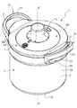
本発明による圧力調理器1は、家庭環境において様々な食品を圧力下で調理するように設計されている。すなわち本発明は家庭用圧力調理器である。
The
したがって、本発明による圧力調理器1は、携帯可能(すなわち手で動かせる)で独立した性質を持つ台所道具である。
Therefore, the
有利なことに、本発明による圧力調理器1は受熱式鍋であり、調理用レンジの最上部といった外部熱源の効果によって圧力を上昇させるように設計されている。
Advantageously, the
本発明による圧力調理器1は、調理用容器を形成し、実質的に軸X−X’に従った回転対称を有利に設けた鍋2を備えていることが好ましい。これ以降の説明において、「軸方向」という用語はこの対称軸X−X’の方向、器具の通常使用時における垂直方向と類似した方向を意味する。鍋2は例えば、また通常、アルミニウムやステンレス鋼のような金属材料から成る未完成金属片を型押しして製造する。
The
鍋2はさらに壁を備えており、この壁自体は、ここで示す実施形態において、
‐ 例えば円盤状をした基部2Aと、
‐ 基部2Aから上昇してこれを包囲している側壁2Bとを備えており、上記側壁2Bは実質的に環状であり、調理する食品を鍋2内に導入できるようにするための上方開口部2Cを画定しており;上記側壁2Bはさらに、鍋2の内部と対向した内面30と、この内面の反対側に位置する外面31とを設けている。
The
-For example a disc-
-A
本発明による圧力調理器1はさらに、上記鍋2に追加してこれと共に調理チャンバを形成するように設計された蓋3を備えており、この調理チャンバは、内部の圧力を上昇させられるように、実質的に不浸透性である、即ち十分な機密性を有することが好ましい。
The
こうして鍋2と蓋3を連結させて形成されたチャンバは、その内部で圧力が相当に増加できるように設計されているため、調理中にチャンバ内の圧力が大気圧よりも大幅に、例えば大気圧を10kPa以上、好ましくは20kPa以上超えて上昇することができる。また、非常に短時間で効率的な調理を可能にするために、内部圧力が大気圧を実質的に40〜110kPa、好ましくは実質的に50〜100kPa超えるようにチャンバを設計することが考えられる。
The chamber formed by connecting the
蓋3は、優先的には鍋2の形状と相補し合う平円形である。必要に応じて蓋3を有利に鍋2上にロックまたはロック解除することができ、蓋3をロックすることで、圧力の影響で蓋3が逃げることなく、チャンバが内部圧力を上昇させられるようになる。
The
この目的のために、圧力調理器1は蓋3を鍋2にロック/ロックする解除手段4を備えていることが好ましい。ロック/ロック解除手段4は、蓋3が鍋2に関連してロックされ(特に図3に示す)、蓋3が鍋2に取り付けられた形状と、蓋3が鍋2に関連してロック解除され(特に図4に示す)、蓋3を鍋2から自由に離すことができる形状との間で移動するように有利に設計されている。
For this purpose, the
図に示すように、ロック/ロック解除手段4は少なくとも、鍋2の壁を通る、即ち鍋の壁の厚さE全体を貫通したロック開口部50A、50B、60A、60Bを備えている。図に示す例では、圧力調理器1は、鍋2の側壁2Bの上方部分80に配置されている、即ち鍋2の上方開口部2Cに向いて配置されていることが好ましい4個のロック開口部50A、50B、60A、60Bを備えている。図に示すように、上記ロック開口部50A、50B、60A、60Bは対毎にグループ化されており、この対どうしは正反対の位置にて対向している。
As shown, the locking / unlocking means 4 comprises at least
本発明によれば、ロック/ロック解除手段4はさらに、少なくとも1本のピン5A、5B、6A、6Bを蓋3上の可動取り付け部と共に備えており、この可動取り付け部は、蓋3が鍋2から離れることをピン/ストライクプレートシステムと同様の方法で完全に防止するために、蓋3がロックされ(特に図3に示す)、ピン5A、5B、6A、6Bが対応するロック開口部50A、50B、60A、60B内に係合した位置と、蓋3を鍋に対して自由に動かせるようにするために、ピン5A、5B、6A、6Bが対応するロック開口部50A、50B、60A、60Bからロック解除され、また特に蓋3と鍋2を離すために使用される、蓋3がロック解除された(図4に示す)位置との間に配置される。
According to the invention, the locking / unlocking means 4 further comprises at least one
図に示すように、圧力調理器1は、ロック開口部50A、50B、60A、60Bの数に対応した多数のピン5A、5B、6A、6Bを備えていることが好ましい。即ち、このケースにおいては、圧力調理器1は、それぞれ開口部50A、50B、60A、60Bと係合するように設計された4本のピン5A、5B、6A、6Bを備えている。ピン5A、5B、6A、6Bは、蓋3上の、格納位置(図4に示す)と展開位置(図3に示す)の間で平行移動できる取り付け部を設けていることが好ましく、上記格納位置では、ピン5A、5B、6A、6Bが蓋3から側方に突出することがないように蓋3内部に格納され、上記展開位置では、各ピン5A、5B、6A、6Bがそれぞれ対応する開口部50A、50B、60A、60B内に突出し、格納位置から展開位置への移行は、鍋2の基部2Aと平行であることが好ましい蓋3の主要延長面と実質的に平行する方向に従った平行動作によって実施される。
As shown to a figure, it is preferable that the
図に示した実施形態によれば、ロック/ロック解除手段4は、X−X’軸に関連して相互に正反対の位置に配置された2個の二また部分5、6を有利に備えており、各二また部分5、6は、ピン5A、5Bから成る第1の対と、ピン6A、6Bから成る第2の対をそれぞれ形成している。例えば、二また部分は、一端がフォーク形状をした一体型の金属板で形成されており、フォークの各爪部分はピン5A、5B、6A、6Bに関連している。各二また部分5、6は、X−X’軸に関連した放射状に移動する取り付け部を設けている。
According to the illustrated embodiment, the locking / unlocking
上記二また部分5、6は、当業者に周知である任意の手段によって駆動される。例えば、図に示すように、ロック/ロック解除手段4は使用者によって手動で制御される。このために、圧力調理器1は、蓋3に搭載され、X−X’軸に従って回転する制御ノブ7Aを備えていることが好ましい。このノブ7Aは、二また部分5、6に機械的に接続しており、一方向へノブ7A回転させると、ピン5A、5B、6A、6Bが放射状に(求心的に)格納され、ノブ7Aをこれと反対の方向へ回転させると、ピン5A、5B、6A、6Bが遠心的に放射状に移動して、各ピンが対応するロック開口部50A、50B、60A、60B内に係合する。二また部分5、6は、当業者に周知の任意の手段で、ノブ7Aによって駆動される。例えば、ノブ7Aを、駆動開口部70を設けたプレートに取り付けることができ、この場合、二また部分5、6自体は、これに対応する、駆動開口部70内に係合するピン51に取り付けられている。したがって、ノブ7Aを回転させるとこれに付随して駆動開口部70が回転し、これにより、傾斜効果で、また二また部分5、6の平行移動案内との組み合わせにて、この回転の動作がこの二また部分5、6の放射状の平行移動動作に変換される。
The
本発明によれば、上記少なくとも1個のロック開口部50A、50B、60A、60Bを覆い隠して、ロック開口部を実質的に調理チャンバの外部から隠すために、圧力調理器1は鍋2に取り付けた(また好ましくは鍋2の側壁2Bに取り付けた)遮蔽部100を備えている。
According to the present invention, the
換言すれば、遮蔽部100の目的は、圧力調理器1が閉鎖されている際に、即ち蓋3が鍋2に取り付けられている際に、開口部50A、50B、60A、60Bを使用者の目から隠すことである。そのため、その動作原理と並んで使用者に最大の恐怖をもたらすロックシステムの一部が使用者に見えなくなる。これにより、圧力調理器1の使用時に使用者が持つ恐怖感が軽減される。さらにこれにより、ロック開口部内に誤って物体が導入されて器具の正確な動作が阻害されることを防止できるので、ロックの信頼性および使用者の安全性も拡大する。
In other words, the purpose of the
これ以外のロック/ロック解除システムを隠すために、圧力調理器1は、特に二また部分5、6とその駆動手段(開口部70、ピン51)を見えないようにするべく蓋3に追加および取り付けたカバー400を備えていることが好ましい。カバー400と、遮蔽部100と、ピンおよびロック開口部の係合に基づいたロック/ロック解除手段4との組み合わせにより、蓋ロックシステムを、非常に単純で信頼性が高くさらに安価な方法で、使用者の目から完全に隠すことが可能となる。
In order to conceal other locking / unlocking systems, the
圧力調理器1は少なくとも、鍋2に取り付けた、また好ましくは鍋2の壁に直接取り付けたグリップ部20を有利に備えている。グリップ部20は、特に上記圧力調理器1が調理済みまたは未調理の食品と、恐らくは調理液とによって充填されている際に、使用者が鍋2自体だけでなく、とりわけ圧力調理器1全体(鍋2と蓋3の組み立てで形成された全体)を扱えるように設計されている。したがって、グリップ部20は、使用者が落下の危険なく必要に応じて圧力調理器1を手で動かすために、圧力調理器1を、容易かつしっかり掴めるように設計されている。図に示すように、グリップ部20は、鍋2の外側の壁に取り付けた少なくとも1本のハンドル21を備えていることが好ましい。上記ハンドル21は、実質的に鍋2からその外部に向かって、X−X’軸に対して放射状に延びている。
The
図に示した例では、圧力調理器1は、X−X’軸に関連して相互に正反対に位置決めされた2本のハンドル21、22を設けており、上記ハンドル21、22は鍋2の側壁2Bから鍋2の外側へ向かって放射状に延びている。
In the example shown in the figure, the
グリップ部20は鍋2上に非常に有利に合致および位置決めされて、上記遮蔽部100を形成している。換言すれば、図に示す例に対応した、この特に好ましい実施形態では、グリップ部20は、圧力調理器1の扱いを可能にし、さらにロック開口部50A、50B、60A、60Bを隠すという2つの機能を設けている。このような2つの機能は、工業製造上の単純性とこれに関連するコスト面に関して特に重要である。
The
好ましくは、また図に示すように、2本のハンドル21、22は同一であり、それぞれが例えば、鍋2の壁に直接、つまり鍋2の外面31に取り付けられた基部210、220を備えている。各基部210、220からは、使用者が手で持てるように設計されたハンドル211、221がそれぞれ延びている。
Preferably, as also shown in the figure, the two
安全で、安定し、信頼性の高いロックを確保するために、上記ピン5A、5B、6A、6Bの一部が、対応するロック開口部50A、50B、60A、60Bを通って鍋2の外側へ突出している、即ち、特に図3、図5に示すように、各ピン5A、5B、6A、6Bが、対応する開口部50A、50B、60A、60Bを貫通して鍋2の反対側へ突出していることが好ましい。
In order to ensure a safe, stable and reliable lock, some of the
図に示すようにこのケースでは、遮蔽部100に、対応するロック開口部50A、50B、60A、60B上に開口した少なくとも1つの目隠しの内部窪みが有利に設けられ、ピンの上記突出部分を内部に収容できるようになっている。
As shown in the figure, in this case, the shielding
その結果、図に示した実施形態によれば、各基部210、220は、目隠しの内部窪みを形成する空洞210A、210B、220A、220Bを有利に設けており、上記空洞は、各ピン5A、5B、6A、6Bが展開位置にあり、外壁31を超えて突出すると、開口部50A、50B、60A、60Bの反対側に位置決めされて、これらのピンをそれぞれ収容するように設計された窪みを形成するように設計されている。
As a result, according to the illustrated embodiment, each base 210, 220 is advantageously provided with
グリップ部20は、グリップ部20と鍋2の間に機械接続、好ましくは組み込まれた機械接続を形成できるようにする、少なくとも1個の取り付け部20Aの手段によって鍋2に取り付けられていることが好ましい。グリップ部20は鍋2とは別個に独立し、取り付け手段20Aによって鍋2に追加および取り付けられていることが好ましい。これにより、取り付け手段20Aが受容的になる、即ちグリップ部20を鍋2に直接取り付けられるようになる。
The
取り付け手段20Aは、少なくとも、鍋2の壁から鍋2の外側へ延びた細長い取り付け要素201Aを有利に備える。取り付け手段20Aはさらに、鍋2の壁を通る、即ち、鍋2の上記壁の厚さE全体を貫通する取り付け口200Aを備えていることが好ましい。このケースでは、また図に示すように、取り付け要素201Aは上記取り付け口200Aを通って延びていることが好ましい。したがって、取り付け要素201Aは、取り付け口200Aから入って鍋の壁の厚さE全体を貫通する。
The attachment means 20A advantageously comprises at least an
取り付け要素201Aは、図に示すように、グリップ部20が付いた外端部202Aと、取り付け口200Aの周囲で鍋2と接触するヘッド部分が据え付けられた内端部203Aとの間で、取り付け口200Aを通って延びていることが好ましい。
As shown in the figure, the
各ハンドル21、22は、同一の方法で、即ち、先述の説明による取り付け口と取り付け要素を備えるこれに関連した取り付け手段の手段によって鍋2に取り付けられていることが好ましい。
Each
取り付け要素201Aは少なくともネジ40を有利に備えており、このネジ40は、ヘッド部40Aと、このヘッド部40Aから取り付け口200Aを通って延びるねじ切りロッド40Bとを具備している。グリップ部20は、ねじきりロッド40Bがねじ込まれるタップ穴50を有利に具備しており、ヘッド部40A(ロッド40Bの直径よりも大きい直径を有する)は鍋2の内部に位置決めされて、この内部と、即ち側壁2Aの内面30に対して接触する。
The
各ハンドル21、22は、その基部210、220の中央に嵌め込んだタップ穴内にねじ込まれるネジの手段によって取り付けられることが好ましい。
Each
取り付け手段20Aは、グリップ部20に取り付けられ、ロック開口部50A、50B、60A、60B内に挿入された支持要素300を少なくとも備えることが好ましい。図に示す例では、支持要素300は、各ハンドル21、22から延びた突出部301、302を備えている。例えば、各ハンドル21、22はそれぞれ対応する2個の突出部301、302を具備しており、この突出部は対応するハンドルと同じ材料から成り、ロック開口部50A、50B、60A、60B内に取り付けられている。したがって、図5に示すように、ハンドル21の2個の突出部のそれぞれはロック開口部60A、60B内に係合し、ハンドル21がネジ40の軸周囲で回転することを防止している。ロック開口部50A、50B、60A、60Bは実質的に横長形状であり、支持要素300を形成している突出部がこれらのロック開口部の一端内に導入されることが好ましい。
The attachment means 20A preferably comprises at least a
そのため、各ロック開口部50A、50B、60A、60Bは、ピン5A、5B、6A、6Bと係合して蓋3を鍋2の上にロックできるようにし、また、上記ハンドルの突出部(またはこれ以外の同等部分)と係合してハンドル21、22を適所に保持するという2つの機能を備えている。
Therefore, each lock opening 50A, 50B, 60A, 60B engages with the
しかしながら、本発明の範囲から逸脱せずに、突出部の代わり、または代用として、壁2Bの外部に向かう変形を提供してボスを作成することも考えられ、このボスは、ハンドル内に取り付けたこれとは反対の形状と係合して、ハンドルを適所に保持するように設計されている。
However, it is also conceivable to create a boss by providing a deformation towards the exterior of the
支持要素300は、ハンドルが、主な取り付けとなる取り付けネジ40Aの軸周囲で回転することを阻止するためにのみ提供されることが好ましい。
The
しかしながら、本発明の範囲から逸脱することなく、単純に取り付けパットをロック開口部50A、50B、60A、60Bに係合させて、ハンドルを取り付けることも考えられる。
However, it is also conceivable to attach the handle by simply engaging the mounting pad with the
またさらに、やはり本発明の範囲から逸脱せずに、側壁2Bの外面に溶着させた金属ブリッジに、ハンドル21、22を通常の方法で取り付けることも考えられる。
Furthermore, it is also conceivable that the
1 家庭用圧力調理器
2 鍋
2A 基部
2B 側璧
2C 上方開口部
3 蓋
4 ロック/ロック解除手段
5A、5B、6A、6B ピン
5、6 二また部分
7A ノブ
20 グリップ部
21、22 ハンドル
20A 取り付け手段
30 内面
31 外面
40 ネジ
40A ヘッド部
40B ねじきりロッド
50 タップ穴
50A、50B、60A、60B ロック開口部
70 駆動開口部
100 遮蔽部
200A 取り付け口
201A 取り付け要素
202A 外端部
203A 内端部
210、220 基部
211、221 ハンドル
210A、210B、220A、220B 内部窪み(空洞)
300 支持要素
400 カバー
DESCRIPTION OF
300
Claims (8)
壁を備えた鍋(2)と、
前記鍋に追加してこれと共に調理チャンバを形成するように設計された蓋(3)と、
前記蓋(3)を前記鍋(2)に対してロック/ロック解除するための手段(4)とを備えており、
前記圧力調理器(1)は、前記ロック/ロック解除手段(4)が、前記鍋(2)の壁を通って嵌め込まれた少なくとも1個のロック開口部(50A、50B、60A、60B)と、蓋(3)上のロック位置とロック解除位置の間に可動取り付け部を設けた1本のピン(5A、5B、6A、6B)とを備えており、前記ロック位置では前記ピン(5A、5B、6A、6B)が前記ロック開口部(50A、50B、60A、60B)内で係合し、前記ロック解除位置では前記ピン(5A、5B、6A、6B)が前記ロック開口部(50A、50B、60A、60B)にロックされておらず、前記圧力調理器(1)はさらに、前記鍋(2)に取り付けて、前記ロック開口部(50A、50B、60A、60B)を覆い隠し、これを実質的に調理チャンバの外側から隠すための遮蔽部(100)を備えていることを特徴とする、家庭用圧力調理器(1)。 A domestic pressure cooker (1), at least,
A pot with walls (2),
A lid (3) designed to add to and form a cooking chamber with the pan;
Means (4) for locking / unlocking the lid (3) with respect to the pan (2);
The pressure cooker (1) includes at least one lock opening (50A, 50B, 60A, 60B) in which the lock / unlock means (4) is fitted through the wall of the pan (2). And a single pin (5A, 5B, 6A, 6B) provided with a movable attachment portion between the lock position and the lock release position on the lid (3), and the pin (5A, 5B, 6A, 6B) are engaged in the lock openings (50A, 50B, 60A, 60B), and in the unlocked position, the pins (5A, 5B, 6A, 6B) are engaged with the lock openings (50A, 6B). 50B, 60A, 60B), the pressure cooker (1) is further attached to the pan (2) to cover the lock opening (50A, 50B, 60A, 60B) The virtually cooked cha Characterized in that it comprises shielding portion for hiding from the outside of the bar (100), a household pressure cooker (1).
Applications Claiming Priority (2)
| Application Number | Priority Date | Filing Date | Title |
|---|---|---|---|
| FR0705264A FR2918863B1 (en) | 2007-07-20 | 2007-07-20 | SELF-CLEANER WITH SCREEN |
| FR0705264 | 2007-07-20 |
Publications (2)
| Publication Number | Publication Date |
|---|---|
| JP2009078128A JP2009078128A (en) | 2009-04-16 |
| JP5193717B2 true JP5193717B2 (en) | 2013-05-08 |
Family
ID=39311048
Family Applications (1)
| Application Number | Title | Priority Date | Filing Date |
|---|---|---|---|
| JP2008187491A Expired - Fee Related JP5193717B2 (en) | 2007-07-20 | 2008-07-18 | Pressure cooker with shielding |
Country Status (8)
| Country | Link |
|---|---|
| US (1) | US8205543B2 (en) |
| EP (1) | EP2016875B1 (en) |
| JP (1) | JP5193717B2 (en) |
| CN (1) | CN101357040B (en) |
| AT (1) | ATE483383T1 (en) |
| DE (1) | DE602008002859D1 (en) |
| ES (1) | ES2359342T3 (en) |
| FR (1) | FR2918863B1 (en) |
Families Citing this family (18)
| Publication number | Priority date | Publication date | Assignee | Title |
|---|---|---|---|---|
| FR2871042B1 (en) * | 2004-06-08 | 2006-12-22 | Seb Sa | FRYER WITH AUTOMATIC COATING OF FATTY MATERIAL |
| DE102013206000A1 (en) * | 2013-04-04 | 2014-10-09 | Gero Vertriebs-Gmbh | cooking pot |
| US10281156B2 (en) * | 2013-04-23 | 2019-05-07 | Alto-Shaam, Inc. | Zero clearance combination oven |
| US9615690B2 (en) | 2014-03-13 | 2017-04-11 | Sunbeam Products, Inc. | Slow cooking appliance with cammed lid latching arrangement |
| FR3036936B1 (en) * | 2015-06-02 | 2019-11-08 | Seb S.A. | BAIONNETTE COOKER WITH A TANK HANDLE |
| FR3046044B1 (en) * | 2015-12-23 | 2018-01-26 | Seb S.A. | PRESSURIZED PRESSURE COOKING APPARATUS WITH IMPROVED SAFETY |
| DE202018006413U1 (en) * | 2017-08-09 | 2020-04-23 | Sharkninja Operating Llc | Cooking device and components thereof |
| USD914447S1 (en) | 2018-06-19 | 2021-03-30 | Sharkninja Operating Llc | Air diffuser |
| USD903413S1 (en) | 2018-08-09 | 2020-12-01 | Sharkninja Operating Llc | Cooking basket |
| USD883015S1 (en) | 2018-08-09 | 2020-05-05 | Sharkninja Operating Llc | Food preparation device and parts thereof |
| USD883014S1 (en) | 2018-08-09 | 2020-05-05 | Sharkninja Operating Llc | Food preparation device |
| USD934027S1 (en) | 2018-08-09 | 2021-10-26 | Sharkninja Operating Llc | Reversible cooking rack |
| EP3931493A1 (en) | 2019-02-25 | 2022-01-05 | SharkNinja Operating LLC | Cooking system with guard |
| US11033146B2 (en) | 2019-02-25 | 2021-06-15 | Sharkninja Operating Llc | Cooking device and components thereof |
| CN112006547B (en) * | 2019-05-31 | 2022-04-22 | 佛山市顺德区美的电热电器制造有限公司 | Upper cover assembly of cooking utensil and cooking utensil |
| USD982375S1 (en) | 2019-06-06 | 2023-04-04 | Sharkninja Operating Llc | Food preparation device |
| USD918654S1 (en) | 2019-06-06 | 2021-05-11 | Sharkninja Operating Llc | Grill plate |
| US11647861B2 (en) | 2020-03-30 | 2023-05-16 | Sharkninja Operating Llc | Cooking device and components thereof |
Family Cites Families (8)
| Publication number | Priority date | Publication date | Assignee | Title |
|---|---|---|---|---|
| US4103801A (en) * | 1977-08-15 | 1978-08-01 | National Presto Industries, Inc. | Pressure cooker with manually-operated cover interlock |
| CN1116846C (en) * | 1997-03-03 | 2003-08-06 | F.B.M.热塑有限责任公司 | Handle for cooking utensils, with movable part for retaining the lid |
| JP3491221B2 (en) * | 1997-11-04 | 2004-01-26 | 株式会社日軽プロダクツ | Vacuum cooking pot |
| FR2783686B1 (en) * | 1998-09-28 | 2000-11-17 | Seb Sa | SAFETY DEVICE AT THE OPENING OF A PRESSURE COOKING APPARATUS WITH BAYONET CLOSURE |
| FR2783687B1 (en) * | 1998-09-28 | 2000-11-17 | Seb Sa | DEVICE FOR LOCKING / UNLOCKING A PRESSURE COOKING APPARATUS WITH BAYONET CLOSURE |
| CN1241124C (en) * | 2001-09-14 | 2006-02-08 | 北京瑞星科技股份有限公司 | Method for fully controlling files in computer system |
| US6669047B2 (en) * | 2001-12-21 | 2003-12-30 | Innovation Ip Holding Co | Button actuated pressure released and locking devices for pressure cookers |
| FR2865621B1 (en) * | 2004-01-29 | 2006-06-02 | Seb Sa | PRESSURIZED FOOD COOKING APPLIANCE WITH ENHANCED GUIDE FOR LOCKING MEANS |
-
2007
- 2007-07-20 FR FR0705264A patent/FR2918863B1/en not_active Expired - Fee Related
-
2008
- 2008-07-17 US US12/174,992 patent/US8205543B2/en not_active Expired - Fee Related
- 2008-07-18 JP JP2008187491A patent/JP5193717B2/en not_active Expired - Fee Related
- 2008-07-21 CN CN2008101341012A patent/CN101357040B/en not_active Expired - Fee Related
- 2008-07-22 ES ES08447038T patent/ES2359342T3/en active Active
- 2008-07-22 DE DE602008002859T patent/DE602008002859D1/en active Active
- 2008-07-22 AT AT08447038T patent/ATE483383T1/en not_active IP Right Cessation
- 2008-07-22 EP EP08447038A patent/EP2016875B1/en not_active Not-in-force
Also Published As
| Publication number | Publication date |
|---|---|
| US8205543B2 (en) | 2012-06-26 |
| EP2016875B1 (en) | 2010-10-06 |
| US20090020020A1 (en) | 2009-01-22 |
| ES2359342T3 (en) | 2011-05-20 |
| CN101357040A (en) | 2009-02-04 |
| EP2016875A1 (en) | 2009-01-21 |
| JP2009078128A (en) | 2009-04-16 |
| FR2918863B1 (en) | 2009-10-09 |
| FR2918863A1 (en) | 2009-01-23 |
| DE602008002859D1 (en) | 2010-11-18 |
| CN101357040B (en) | 2012-08-22 |
| ATE483383T1 (en) | 2010-10-15 |
Similar Documents
| Publication | Publication Date | Title |
|---|---|---|
| JP5193717B2 (en) | Pressure cooker with shielding | |
| JP5606670B2 (en) | Pressure cooker with plastic decoration | |
| JP5395376B2 (en) | Pressure cooker with built-in information window | |
| JP6211323B2 (en) | Cookware for cooking food under pressure with improved control device | |
| US8096440B2 (en) | Pressure cooker equipped with a gripping part attached to the pan | |
| US8546731B2 (en) | Electrical appliance for cooking food | |
| JP4190559B2 (en) | Equipment for cooking food under pressure | |
| JP5845255B2 (en) | Pressure cooker lid | |
| JP4235669B2 (en) | Pressure cooker with a single control member for decompression and locking / unlocking | |
| US20210000292A1 (en) | Combined air fryer and pressure cooker lid | |
| AU2014319872B2 (en) | Pressure cooker | |
| WO2020134318A1 (en) | Cooking utensil | |
| CN112137401B (en) | Electric cooking appliance with detachable heating device | |
| US20130025470A1 (en) | Utensil with simplified handling | |
| ES2946047T3 (en) | Cooking appliance for cooking food with or without pressure | |
| JP3208768U (en) | kitchenware | |
| KR20110083850A (en) | Electric rice cooker | |
| JP2012179147A (en) | Handle with safety whistle | |
| KR20170110999A (en) | Safe pot with overheat automatic cutoff device | |
| JP6955247B2 (en) | Detachable gripper for ear-shaped holding member of cookware | |
| KR20100007322U (en) | Double frying pan | |
| JPH0570450B2 (en) | ||
| CN212912755U (en) | Cooking utensil | |
| KR20170106092A (en) | Cookware assembly | |
| CN207236662U (en) | Temperature controller mounting structure and cooking utensils |
Legal Events
| Date | Code | Title | Description |
|---|---|---|---|
| RD01 | Notification of change of attorney |
Free format text: JAPANESE INTERMEDIATE CODE: A7426 Effective date: 20090129 |
|
| A521 | Request for written amendment filed |
Free format text: JAPANESE INTERMEDIATE CODE: A821 Effective date: 20090129 |
|
| A621 | Written request for application examination |
Free format text: JAPANESE INTERMEDIATE CODE: A621 Effective date: 20110630 |
|
| RD02 | Notification of acceptance of power of attorney |
Free format text: JAPANESE INTERMEDIATE CODE: A7422 Effective date: 20120508 |
|
| TRDD | Decision of grant or rejection written | ||
| A01 | Written decision to grant a patent or to grant a registration (utility model) |
Free format text: JAPANESE INTERMEDIATE CODE: A01 Effective date: 20130108 |
|
| A61 | First payment of annual fees (during grant procedure) |
Free format text: JAPANESE INTERMEDIATE CODE: A61 Effective date: 20130204 |
|
| R150 | Certificate of patent or registration of utility model |
Free format text: JAPANESE INTERMEDIATE CODE: R150 |
|
| FPAY | Renewal fee payment (event date is renewal date of database) |
Free format text: PAYMENT UNTIL: 20160208 Year of fee payment: 3 |
|
| R250 | Receipt of annual fees |
Free format text: JAPANESE INTERMEDIATE CODE: R250 |
|
| R250 | Receipt of annual fees |
Free format text: JAPANESE INTERMEDIATE CODE: R250 |
|
| LAPS | Cancellation because of no payment of annual fees |