EP2937027B1 - Household cooking appliance comprising a removable container which can be arranged on a housing by a simple translation movement - Google Patents
Household cooking appliance comprising a removable container which can be arranged on a housing by a simple translation movement Download PDFInfo
- Publication number
- EP2937027B1 EP2937027B1 EP15163874.9A EP15163874A EP2937027B1 EP 2937027 B1 EP2937027 B1 EP 2937027B1 EP 15163874 A EP15163874 A EP 15163874A EP 2937027 B1 EP2937027 B1 EP 2937027B1
- Authority
- EP
- European Patent Office
- Prior art keywords
- housing
- boss
- container
- electrical appliance
- household electrical
- Prior art date
- Legal status (The legal status is an assumption and is not a legal conclusion. Google has not performed a legal analysis and makes no representation as to the accuracy of the status listed.)
- Active
Links
Images


Classifications
-
- A—HUMAN NECESSITIES
- A47—FURNITURE; DOMESTIC ARTICLES OR APPLIANCES; COFFEE MILLS; SPICE MILLS; SUCTION CLEANERS IN GENERAL
- A47J—KITCHEN EQUIPMENT; COFFEE MILLS; SPICE MILLS; APPARATUS FOR MAKING BEVERAGES
- A47J43/00—Implements for preparing or holding food, not provided for in other groups of this subclass
- A47J43/04—Machines for domestic use not covered elsewhere, e.g. for grinding, mixing, stirring, kneading, emulsifying, whipping or beating foodstuffs, e.g. power-driven
- A47J43/07—Parts or details, e.g. mixing tools, whipping tools
- A47J43/0716—Parts or details, e.g. mixing tools, whipping tools for machines with tools driven from the lower side
-
- A—HUMAN NECESSITIES
- A47—FURNITURE; DOMESTIC ARTICLES OR APPLIANCES; COFFEE MILLS; SPICE MILLS; SUCTION CLEANERS IN GENERAL
- A47J—KITCHEN EQUIPMENT; COFFEE MILLS; SPICE MILLS; APPARATUS FOR MAKING BEVERAGES
- A47J43/00—Implements for preparing or holding food, not provided for in other groups of this subclass
- A47J43/04—Machines for domestic use not covered elsewhere, e.g. for grinding, mixing, stirring, kneading, emulsifying, whipping or beating foodstuffs, e.g. power-driven
- A47J43/07—Parts or details, e.g. mixing tools, whipping tools
- A47J43/0727—Mixing bowls
Definitions
- the present invention relates to the general technical field of electrical household appliances for culinary preparation comprising a housing enclosing a motor and comprising a removable container which can be arranged on the housing by a simple vertical translational movement, the container comprising a working tool intended to be driven in rotation by the motor and comprising a base comprising a peripheral skirt which fits on centering reliefs formed on the housing.
- a food preparation apparatus comprising a motor housing on which can engage a container by a simple vertical translation movement.
- the device comprises resilient locking means for immobilizing the container on the motor housing and in particular to prevent it from being lifted under the effect of the return means of the safety control.
- an object of the present invention is to provide an electrical appliance for culinary preparation overcoming these disadvantages and which is simple and economical to achieve.
- Another object of the present invention is to provide an apparatus providing a great ergonomics of use.
- the invention relates to an electrical household appliance for culinary preparation
- a housing enclosing a motor and a removable container which can be arranged, in an operating position on the housing, by a simple vertical translational movement
- the container comprising a working tool intended to be rotated by the motor and comprising a base comprising a peripheral skirt fitting on one or several centering reliefs formed on the housing
- the housing comprises at least one support boss formed on an outer wall of one of the centering reliefs, the boss engaging in an opening formed on the peripheral skirt of the base for immobilizing the container in position on the housing in the vertical direction of engagement.
- placing the container on the housing by a simple vertical translational movement it is meant placing the container in an operating position of the device that does not require rotation of the container on the housing, to ensure its locking. and its immobilization on the housing, as is usually the case with a bayonet type connection.
- the centering reliefs comprise a first boss and a second holding boss disposed on two distinct faces of the case, the first and second bosses engaging in corresponding openings in the peripheral skirt of the case. base of the container.
- Such a feature makes it possible to further improve the maintenance of the container on the housing.
- the first boss is carried by a tongue provided to deform elastically when pressure is exerted on the first boss.
- Such a feature allows to limit the effort to achieve commitment and disengagement of the first boss in the opening.
- the resilient tongue is made in a piece which is attached in an opening of the outer wall of the centering relief.
- Such a characteristic makes it possible to produce the elastic tongue in a material different from that used for the case, having for example a better resistance to fatigue. Such a characteristic also makes it possible to simplify the manufacturing process.
- the second boss is carried by a wall having greater rigidity than the tongue supporting the first boss.
- Such a feature has the advantage of creating an anchor point at the second boss having greater resistance to engagement and disengagement than the anchor point achieved by engagement of the first boss, thereby enabling improve the firmness of maintaining the container on the housing.
- the second boss is made directly on the outer wall of the centering relief, the latter being devoid of cutting to facilitate the elastic deformation of the wall.
- the housing comprises a safety control which is returned to a rest position by return means, the safety control being disposed closer to the second boss than the first boss.
- Such a feature has the advantage of having the safety control in the vicinity of the boss where the container is held most firmly in position, thus ensuring a better positioning of the container on the housing and a good activation of the safety control.
- the first boss is carried by an outer face of a centering relief extending along the rear face of the housing and the second boss is carried by an outer face of a relief of centering extending along the front face of the housing, the outer faces of the centering reliefs fitting into the peripheral skirt of the base of the container when the container is disposed on the housing.
- the container may be disposed on the housing according to several predetermined orientations.
- Such a feature simplifies the establishment of the container on the housing and allows in particular, when the container is provided with a handle, to orient the handle of the container in the most ergonomic direction for the user, depending on whether the latter is right-handed or left-handed.
- the peripheral skirt has a number of openings greater than the number of bosses, the openings of the peripheral skirt coming opposite the boss, or facing a passage for air circulation. , when the container is disposed on the housing according to any of the orientations permitted by the centering reliefs.
- Such a feature allows to have, through the openings unoccupied by the bosses, a flow of air participating in the cooling of the device.
- the passage for the circulation of air is constituted by a space formed between the centering reliefs.
- the base of the container has a substantially square cross section, the base can be arranged on the housing in four different orientations offset from each other by 90 °.
- the base comprises an opening on each of the four faces of the peripheral skirt, two of the openings receiving the first and second bosses when the container is disposed on the housing, the two other openings facing each other. a space between the two centering reliefs to allow the circulation of a flow of air contributing to the cooling of the engine.
- the openings have the shape of a slot, the boss having the shape of a bead having a shape adapted to be introduced into the openings.
- the boss being introduced into the slot extends over a height of between 1 and 3 mm and has a width greater than 1 cm and preferably a width of about 3 cm.
- Such a characteristic makes it possible to obtain both a good retention of the container and a good visual perception of the means for holding the container.
- the peripheral skirt is made of a transparent material.
- the figure 1 illustrates an electrical household appliance for culinary preparation comprising a motor housing 1 and a receptacle 2 intended to be placed on the motor housing 1 in several angular positions, the receptacle 2 comprising a removable cover 3 and being provided with a handle.
- the container 2 is preferably made of plastic, for example by a molding method, and comprises a transparent envelope 20 defining the useful volume of the container 2 and a bottom, visible on the figure 6 , conventionally supporting a working tool 4 intended to be rotated by a motor 5, visible on the figure 6 , integrated in the housing 1.
- the housing 1 has a substantially square cross section with rounded corners and has a front face provided with a control button 10 for controlling the operation of the motor 5, the housing 1 comprising an upper end provided with a receiving base on which the container 2 can come to rest.
- the receiving base comprises two centering reliefs 11 on which the container 2 can engage vertically in four angular positions offset relative to each other by 90 °, the container 2 comprising an enlarged base 21 comprising a peripheral skirt 22 of substantially square section fitting on the centering reliefs 11 by matching the shape of the latter.
- one of the two centering reliefs 11 extends along the front face of the housing 1, the other centering relief 11 extending along the rear face of the housing 1, the two centering reliefs 11 being separated at their longitudinal end by a space 12, a width of the order of 35 mm.
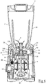
- the two centering projections 11 have an inner wall of circular shape which delimit between them a cylindrical cavity receiving a rotary driver 13 integral with the output shaft of the motor 5, the working tool 4 having a shaft passing through the bottom of the container 2 whose lower end is provided with a bushing 40, visible on the figure 5 , coming to mate on the driver 13 when the container 2 is properly disposed on the housing 1.
- the receiving base also comprises a stud 14 disposed on the edge of the centering relief 11 extending along the front face, the stud 14 comprising a slot giving access to a security command 6, visible on the figures 3 and 6 , being able to move vertically within the housing 1 engine against a spring 60 of return to actuate, in a manner known per se, a safety switch disposed on the motor supply circuit 5.
- the container 2 is immobilized on the receiving base by means of a first holding boss 15 formed on an outer wall of the centering relief 11 extending along the rear face of the housing 1 and a second boss 16 of maintenance provided on an outer wall of the centering relief 11 extending along the front face of the housing 1, the first and second bosses 15, 16 coming into force in openings 23 formed on the peripheral skirt 22 of the base 21 of the container 2.
- each lateral face of the peripheral skirt 22 has an opening 23 capable of receiving the first or second boss 15, 16 and the container 2 comprises an annular ring 24 extending inside the peripheral skirt 22, comprising cams 24A. from actuating the safety control 6 when the container 2 is disposed on the housing 1 according to any one of four permitted angular positions.
- the first boss 15 is carried by a tab 70 designed to deform elastically and the second boss 16 is formed directly on the outer wall of the centering relief 11 located on the front of the housing without any cut is provided around the second boss 16 to promote the deformation of the wall.
- the first boss 15 is advantageously made in an independent plastic part 7, illustrated in isolation on the Figures 7A and 7B , reported in an opening 17 of the outer wall of the centering relief 11, the piece 7 comprising a cutout 71 in the shape of a U around the tongue 70 and fastening clips 72 ensuring easy assembly of the piece 7 in the opening 17 by elastic locking.
- the openings 23 of the peripheral skirt 22 have the shape of a slit extending horizontally over a width of the order of 35 mm and a height of about 5 mm, the first and second bosses 15, 16 having the shape of a bead having a width and a length adapted to be introduced into the openings 23 of the peripheral skirt 22 of the container 2, the bead advantageously having a thickness of about 1.5 mm and a substantially triangular cross section.
- the appliance thus produced has the advantage of providing great ergonomics of use.
- the container 2 can then be locked on the housing 1 by exerting a simple downward pressure to fit the peripheral skirt 22 on the reliefs centering 11 and to bring the first and second bosses 15, 16 in the openings 23 of the peripheral skirt 22, this engagement of the first and second bosses 15, 16 in the openings 23 of the peripheral skirt 22 having the advantage of be perfectly visible by the user so that the latter is visually informed of the proper holding of the container 2 on the housing 1, thus improving the safety and ergonomics of use of the device.
- the safety control 6 located near the second boss 16 is activated by one of the cams 24A of the crown 24 of the receptacle, and the second boss 16 is engaged firmly in the opening 23.
- the high resistance to deformation exerted by the outer wall of the centering relief 11 located along the front face of the housing, while the engagement of the first boss 15 is performed with greater ease because of the presence of the tongue 70 provided to deform elastically.
- the openings 23 of the peripheral skirt not receiving the first and second bosses 15, 16 have, for their part, the advantage of being opposite the space 12 formed between the two ends Longitudinal reliefs of centering 11. This allows to establish a flow of air between the cavity receiving the coach and the outside of the container, as is illustrated by the arrows F on the figure 1 , to improve the cooling of the motor, the upper wall of the housing 1 having ventilation slots 18, visible on the figure 6 , disposed under a protective disk 13A integral with the driver 13, and the bottom of the housing 1 having a ventilation grid 19 allowing the passage of a flow of air inside the motor housing 1, illustrated by the arrows F, then towards the cavity receiving the trainer 13.
- such a container also has the advantage of being very easily removable from the base by simply lifting the container so that the tongue supporting the first boss deforms elastically and lets out the first boss of the opening, thus allowing a slight tilting of the container towards the front of the apparatus and the disengagement of the second boss.
- the base of the container and the receiving base of the housing may not have a substantially square cross section but have the shape of a regular polygon, such as a triangle, a pentagon, a hexagon ...
- the housing may comprise a single centering relief extending over the entire periphery of the base, the centering relief having a light coming opposite the openings the peripheral skirt of the container not receiving the holding bosses when the container is disposed on the housing, to allow the circulation of a flow of air.
- the working tool may be mounted on a removable base of the container envelope.
- the mixer-type container illustrated in the embodiment described can be replaced by any type of container that can be used as an accessory on a motor housing, such as a mini-chopper type container, or a container containing a centrifuge type tool, this container may comprise a valve or a side chute for evacuation to a second container disposed at the edge of the motor housing.
Description
La présente invention se rapporte au domaine technique général des appareils électroménagers de préparation culinaire comportant un boîtier renfermant un moteur et comprenant un récipient amovible pouvant être disposé sur le boîtier par un simple mouvement de translation verticale, le récipient comprenant un outil de travail destiné à être entraîné en rotation par le moteur et comportant une embase comprenant une jupe périphérique venant s'emboîter sur des reliefs de centrage ménagés sur le boîtier.The present invention relates to the general technical field of electrical household appliances for culinary preparation comprising a housing enclosing a motor and comprising a removable container which can be arranged on the housing by a simple vertical translational movement, the container comprising a working tool intended to be driven in rotation by the motor and comprising a base comprising a peripheral skirt which fits on centering reliefs formed on the housing.
Il est connu, de la demande de brevet
Cependant, un tel appareil présente l'inconvénient de ne pas permettre à l'utilisateur de visualiser le bon engagement des moyens de verrouillage. De plus, les moyens de verrouillage divulgués dans ce document ne permettent pas de garantir un maintien ferme du récipient sur le boîtier.However, such a device has the disadvantage of not allowing the user to view the proper engagement of the locking means. In addition, the locking means disclosed in this document do not ensure a firm hold of the container on the housing.
Aussi, un but de la présente invention est de proposer un appareil électroménager de préparation culinaire remédiant à ces inconvénients et qui soit simple et économique à réaliser. Un autre but de la présente invention est de proposer un appareil procurant une grande ergonomie d'utilisation.Also, an object of the present invention is to provide an electrical appliance for culinary preparation overcoming these disadvantages and which is simple and economical to achieve. Another object of the present invention is to provide an apparatus providing a great ergonomics of use.
A cet effet, l'invention se rapporte à un appareil électroménager de préparation culinaire comportant un boîtier renfermant un moteur et un récipient amovible pouvant être disposé, dans une position de fonctionnement sur le boîtier, par un simple mouvement de translation verticale, le récipient comprenant un outil de travail destiné à être entraîné en rotation par le moteur et comportant une embase comprenant une jupe périphérique venant s'emboîter sur un ou plusieurs reliefs de centrage ménagés sur le boîtier, caractérisé en ce que le boîtier comporte au moins un bossage de maintien ménagé sur une paroi externe d'un des reliefs de centrage, le bossage venant s'engager dans une ouverture ménagée sur la jupe périphérique de l'embase pour immobiliser le récipient en position sur le boîtier selon la direction verticale d'engagement.To this end, the invention relates to an electrical household appliance for culinary preparation comprising a housing enclosing a motor and a removable container which can be arranged, in an operating position on the housing, by a simple vertical translational movement, the container comprising a working tool intended to be rotated by the motor and comprising a base comprising a peripheral skirt fitting on one or several centering reliefs formed on the housing, characterized in that the housing comprises at least one support boss formed on an outer wall of one of the centering reliefs, the boss engaging in an opening formed on the peripheral skirt of the base for immobilizing the container in position on the housing in the vertical direction of engagement.
On obtient ainsi un appareil dans lequel le maintien du récipient sur le boîtier est réalisé efficacement par des moyens simples à mettre en oeuvre, la coopération du bossage avec l'ouverture de la jupe périphérique présentant l'avantage d'être parfaitement visible par l'utilisateur de sorte que ce dernier est visuellement informé du bon engagement du récipient sur le boîtier.An apparatus is thus obtained in which the holding of the container on the housing is effected effectively by simple means to implement, the cooperation of the boss with the opening of the peripheral skirt having the advantage of being perfectly visible by the user so that the latter is visually informed of the good engagement of the container on the housing.
Par une mise en place du récipient sur le boîtier par un simple mouvement de translation verticale, on entend une mise en place du récipient dans une position de fonctionnement de l'appareil ne nécessitant pas de rotation du récipient sur le boîtier, pour assurer son verrouillage et son immobilisation sur le boîtier, tel que cela est habituellement le cas avec une liaison de type baïonnette.By placing the container on the housing by a simple vertical translational movement, it is meant placing the container in an operating position of the device that does not require rotation of the container on the housing, to ensure its locking. and its immobilization on the housing, as is usually the case with a bayonet type connection.
Selon une autre caractéristique de l'invention, les reliefs de centrage comportent un premier bossage et un deuxième bossage de maintien disposés sur deux faces distinctes du boîtier, les premier et deuxième bossages venant s'engager dans des ouvertures correspondantes de la jupe périphérique de l'embase du récipient.According to another characteristic of the invention, the centering reliefs comprise a first boss and a second holding boss disposed on two distinct faces of the case, the first and second bosses engaging in corresponding openings in the peripheral skirt of the case. base of the container.
Une telle caractéristique permet d'améliorer encore le maintien du récipient sur le boîtier.Such a feature makes it possible to further improve the maintenance of the container on the housing.
Selon une autre caractéristique de l'invention, le premier bossage est porté par une languette prévue pour se déformer élastiquement lorsqu'une pression est exercée sur le premier bossage.According to another characteristic of the invention, the first boss is carried by a tongue provided to deform elastically when pressure is exerted on the first boss.
Une telle caractéristique permet de limiter l'effort pour parvenir à l'engagement et au désengagement du premier bossage dans l'ouverture.Such a feature allows to limit the effort to achieve commitment and disengagement of the first boss in the opening.
Selon une autre caractéristique de l'invention, la languette élastique est réalisée dans une pièce qui est rapportée dans une ouverture de la paroi externe du relief de centrage.According to another characteristic of the invention, the resilient tongue is made in a piece which is attached in an opening of the outer wall of the centering relief.
Une telle caractéristique permet de réaliser la languette élastique dans un matériau différent de celui utilisé pour le boîtier, possédant par exemple une meilleure résistance à la fatigue. Une telle caractéristique permet également de simplifier le procédé de fabrication.Such a characteristic makes it possible to produce the elastic tongue in a material different from that used for the case, having for example a better resistance to fatigue. Such a characteristic also makes it possible to simplify the manufacturing process.
Selon encore une autre caractéristique de l'invention, le deuxième bossage est porté par une paroi présentant une plus grande rigidité que la languette supportant le premier bossage.According to yet another characteristic of the invention, the second boss is carried by a wall having greater rigidity than the tongue supporting the first boss.
Une telle caractéristique présente l'avantage de créer un point d'ancrage au niveau du deuxième bossage présentant une plus grande résistance à l'engagement et au désengagement que le point d'ancrage réalisé par l'engagement du premier bossage, permettant ainsi d'améliorer la fermeté du maintien du récipient sur le boîtier.Such a feature has the advantage of creating an anchor point at the second boss having greater resistance to engagement and disengagement than the anchor point achieved by engagement of the first boss, thereby enabling improve the firmness of maintaining the container on the housing.
Selon encore une autre caractéristique de l'invention, le deuxième bossage est réalisé directement sur la paroi externe du relief de centrage, cette dernière étant dépourvue de découpe pour faciliter la déformation élastique de la paroi.According to yet another characteristic of the invention, the second boss is made directly on the outer wall of the centering relief, the latter being devoid of cutting to facilitate the elastic deformation of the wall.
Une telle solution technique présente l'avantage d'être simple et économique à mettre en oeuvre. Elle présente également l'avantage de ne pas dégrader de façon importante l'esthétique du boîtier.Such a technical solution has the advantage of being simple and economical to implement. It also has the advantage of not significantly degrade the aesthetics of the housing.
Selon une autre caractéristique de l'invention, le boîtier comporte une commande de sécurité qui est ramenée dans une position de repos par des moyens de rappel, la commande de sécurité étant disposée plus près du deuxième bossage que du premier bossage.According to another characteristic of the invention, the housing comprises a safety control which is returned to a rest position by return means, the safety control being disposed closer to the second boss than the first boss.
Une telle caractéristique présente l'avantage de disposer la commande de sécurité au voisinage du bossage où le récipient est maintenu le plus fermement en position, permettant ainsi de garantir un meilleur positionnement du récipient sur le boîtier et une bonne activation de la commande de sécurité.Such a feature has the advantage of having the safety control in the vicinity of the boss where the container is held most firmly in position, thus ensuring a better positioning of the container on the housing and a good activation of the safety control.
Selon une autre caractéristique de l'invention, le premier bossage est porté par une face externe d'un relief de centrage s'étendant le long de la face arrière du boîtier et le deuxième bossage est porté par une face externe d'un relief de centrage s'étendant le long de la face avant du boîtier, les faces externes des reliefs de centrage venant s'emboîter dans la jupe périphérique de l'embase du récipient lorsque le récipient est disposé sur le boîtier.According to another characteristic of the invention, the first boss is carried by an outer face of a centering relief extending along the rear face of the housing and the second boss is carried by an outer face of a relief of centering extending along the front face of the housing, the outer faces of the centering reliefs fitting into the peripheral skirt of the base of the container when the container is disposed on the housing.
Selon une autre caractéristique de l'invention, le récipient peut être disposé sur le boîtier selon plusieurs orientations prédéterminées.According to another characteristic of the invention, the container may be disposed on the housing according to several predetermined orientations.
Une telle caractéristique simplifie la mise en place du récipient sur le boîtier et permet notamment, lorsque le récipient est pourvu d'une poignée, d'orienter la poignée du récipient selon la direction la plus ergonomique pour l'utilisateur, selon que ce dernier soit droitier ou gaucher.Such a feature simplifies the establishment of the container on the housing and allows in particular, when the container is provided with a handle, to orient the handle of the container in the most ergonomic direction for the user, depending on whether the latter is right-handed or left-handed.
Selon une autre caractéristique de l'invention, la jupe périphérique comporte un nombre d'ouvertures supérieur au nombre de bossages, les ouvertures de la jupe périphérique venant soit en regard du bossage, soit en regard d'un passage pour la circulation d'air, lorsque le récipient est disposé sur le boîtier selon l'une quelconque des orientations permises par les reliefs de centrage.According to another characteristic of the invention, the peripheral skirt has a number of openings greater than the number of bosses, the openings of the peripheral skirt coming opposite the boss, or facing a passage for air circulation. , when the container is disposed on the housing according to any of the orientations permitted by the centering reliefs.
Une telle caractéristique permet d'avoir, par les ouvertures inoccupées par les bossages, une circulation d'air participant au refroidissement de l'appareil.Such a feature allows to have, through the openings unoccupied by the bosses, a flow of air participating in the cooling of the device.
Selon une autre caractéristique de l'invention, le passage pour la circulation de l'air est constitué par un espace ménagé entre les reliefs de centrage.According to another characteristic of the invention, the passage for the circulation of air is constituted by a space formed between the centering reliefs.
Selon une autre caractéristique de l'invention, l'embase du récipient présente une section transversale sensiblement carrée, l'embase pouvant être disposée sur le boîtier selon quatre orientations distinctes décalées l'une par rapport à l'autre de 90°.According to another characteristic of the invention, the base of the container has a substantially square cross section, the base can be arranged on the housing in four different orientations offset from each other by 90 °.
Selon une autre caractéristique de l'invention, l'embase comporte une ouverture sur chacune des quatre faces de la jupe périphérique, deux des ouvertures recevant les premier et deuxième bossages lorsque le récipient est disposé sur le boîtier, les deux autres ouvertures venant en regard d'un espace ménagé entre les deux reliefs de centrage pour permettre la circulation d'un flux d'air contribuant au refroidissement du moteur.According to another characteristic of the invention, the base comprises an opening on each of the four faces of the peripheral skirt, two of the openings receiving the first and second bosses when the container is disposed on the housing, the two other openings facing each other. a space between the two centering reliefs to allow the circulation of a flow of air contributing to the cooling of the engine.
Selon une autre caractéristique de l'invention, les ouvertures présentent la forme d'une fente, le bossage présentant la forme d'un bourrelet possédant une forme adaptée pour s'introduire dans les ouvertures.According to another characteristic of the invention, the openings have the shape of a slot, the boss having the shape of a bead having a shape adapted to be introduced into the openings.
Selon une autre caractéristique de l'invention, le bossage s'introduisant dans la fente s'étend sur une hauteur comprise entre 1 et 3 mm et présente une largeur supérieure à 1 cm et préférentiellement une largeur de l'ordre de 3 cm.According to another characteristic of the invention, the boss being introduced into the slot extends over a height of between 1 and 3 mm and has a width greater than 1 cm and preferably a width of about 3 cm.
Une telle caractéristique permet d'obtenir à la fois un bon maintien du récipient et une bonne perception visuelle des moyens de maintien du récipient.Such a characteristic makes it possible to obtain both a good retention of the container and a good visual perception of the means for holding the container.
Selon une autre caractéristique de l'invention, la jupe périphérique est réalisée dans un matériau transparent.According to another characteristic of the invention, the peripheral skirt is made of a transparent material.
Une telle caractéristique permet d'améliorer encore la visibilité sur l'engagement des bossages.Such a characteristic makes it possible to further improve the visibility on the engagement of the bosses.
On comprendra mieux les buts, aspects et avantages de la présente invention, d'après la description donnée ci-après d'un mode particulier de réalisation de l'invention présenté à titre d'exemple non limitatif, en se référant aux dessins annexés dans lesquels :
- la
figure 1 est une vue en perspective, de trois quart avant, d'un appareil électroménager de préparation culinaire selon un mode particulier de réalisation de l'invention, le récipient étant accouplé au boîtier moteur ; - la
figure 2 est une vue en perspective, de trois quart arrière, de l'appareil de préparation culinaire de lafigure 1 , le récipient étant désaccouplé du boîtier moteur ; - la
figure 3 est une vue en perspective du dessus du boîtier moteur de l'appareil de préparation culinaire de lafigure 1 ; - la
figure 4 est une vue de côté de la face arrière du boîtier de lafigure 3 ; - la
figure 5 est une vue en perspective du dessous du récipient de l'appareil de lafigure 1 ; - la
figure 6 est une vue en coupe longitudinale de l'appareil de lafigure 1 ; - les
figures 7A et 7B représentent des vues en perspective de la pièce à déformation élastique supportant le bossage disposé sur la face arrière du boîtier.
- the
figure 1 is a perspective view, three quarter front, of an electrical household appliance for culinary preparation according to a particular embodiment of the invention, the container being coupled to the motor housing; - the
figure 2 is a perspective view, three quarter rear, of the food preparation apparatus of thefigure 1 , the container being uncoupled from the motor housing; - the
figure 3 is a perspective view of the top of the motor housing of the food preparation apparatus of thefigure 1 ; - the
figure 4 is a side view of the back side of the case of thefigure 3 ; - the
figure 5 is a perspective view of the bottom of the device's container thefigure 1 ; - the
figure 6 is a longitudinal sectional view of the apparatus of thefigure 1 ; - the
Figures 7A and 7B are perspective views of the resilient deformation piece supporting the boss disposed on the rear face of the housing.
Seuls les éléments nécessaires à la compréhension de l'invention ont été représentés. Pour faciliter la lecture des dessins, les mêmes éléments portent les mêmes références d'une figure à l'autre.Only the elements necessary for the understanding of the invention have been represented. To facilitate the reading of the drawings, the same elements bear the same references from one figure to another.
La
Le récipient 2 est préférentiellement réalisé en matière plastique, par exemple par un procédé de moulage, et comporte une enveloppe 20 transparente définissant le volume utile du récipient 2 ainsi qu'un fond, visible sur la
Conformément aux
De manière préférentielle, le socle de réception comporte deux reliefs de centrage 11 sur lesquels le récipient 2 peut s'engager verticalement selon quatre positions angulaires décalées l'une par rapport à l'autre de 90°, le récipient 2 comprenant une embase 21 élargie comprenant une jupe périphérique 22 de section sensiblement carrée venant s'emboîter sur les reliefs de centrage 11 en épousant la forme de ces derniers.Preferably, the receiving base comprises two
Comme on peut le voir sur la
Les deux reliefs de centrage 11 présentent une paroi interne de forme circulaire qui délimitent entre elles une cavité cylindrique recevant un entraîneur 13 rotatif solidaire de l'arbre de sortie du moteur 5, l'outil de travail 4 comportant un arbre traversant le fond du récipient 2 dont l'extrémité inférieure est munie d'une douille 40, visible sur la
Le socle de réception comporte également un plot 14 disposé en bordure du relief de centrage 11 s'étendant le long de la face avant, le plot 14 comportant une fente donnant accès à une commande de sécurité 6, visible sur les
Le récipient 2 est immobilisé sur le socle de réception au moyen d'un premier bossage 15 de maintien ménagé sur une paroi externe du relief de centrage 11 s'étendant le long de la face arrière du boîtier 1 et d'un deuxième bossage 16 de maintien ménagé sur une paroi externe du relief de centrage 11 s'étendant le long de la face avant du boîtier 1, les premier et deuxième bossages 15, 16 venant s'introduire en force dans des ouvertures 23 ménagées sur la jupe périphérique 22 de l'embase 21 du récipient 2.The
Comme on peut mieux le voir sur la
De manière préférentielle, le premier bossage 15 est porté par une languette 70 prévue pour se déformer élastiquement et le deuxième bossage 16 est ménagé directement sur la paroi externe du relief de centrage 11 située sur la face avant du boîtier sans qu'aucune découpe ne soit prévue autour du deuxième bossage 16 pour favoriser la déformation de la paroi.Preferably, the
Le premier bossage 15 est avantageusement réalisé dans une pièce 7 plastique indépendante, illustrée isolément sur les
A titre d'exemple, les ouvertures 23 de la jupe périphérique 22 présentent la forme d'une fente s'étendant horizontalement sur une largeur de l'ordre de 35 mm et sur une hauteur de l'ordre de 5 mm, les premier et deuxième bossages 15, 16 présentant la forme d'un bourrelet présentant une largeur et une longueur adaptées pour s'introduire dans les ouvertures 23 de la jupe périphérique 22 du récipient 2, le bourrelet présentant avantageusement une épaisseur de l'ordre 1,5 mm et une section transversale sensiblement triangulaire.For example, the
L'appareil électroménager ainsi réalisé présente l'avantage de procurer une grande ergonomie d'utilisation.The appliance thus produced has the advantage of providing great ergonomics of use.
En effet, lorsque l'utilisateur souhaite mettre en place le récipient 2 sur le boîtier 1, il lui suffit d'amener l'embase 21 sur le socle de réception du boîtier 1 et de l'orienter selon l'une quelconque des quatre orientations autorisant l'engagement de la jupe périphérique 22 de forme carrée sur les deux reliefs de centrage 11. Le récipient 2 peut alors être verrouillé sur le boîtier 1 en exerçant une simple pression vers le bas afin d'emboiter la jupe périphérique 22 sur les reliefs de centrage 11 et d'amener les premier et deuxième bossages 15, 16 dans les ouvertures 23 de la jupe périphérique 22, cet engagement des premier et deuxième bossages 15, 16 dans les ouvertures 23 de la jupe périphérique 22 présentant l'avantage d'être parfaitement visible par l'utilisateur de sorte que ce dernier est visuellement informé du bon maintien du récipient 2 sur le boîtier 1, améliorant ainsi la sécurité et l'ergonomie d'utilisation de l'appareil.Indeed, when the user wishes to place the
Lors de cet emboitement, la commande de sécurité 6 se trouvant à proximité du deuxième bossage 16 se trouve activée par l'une des cames 24A de la couronne 24 du récipient, et le deuxième bossage 16 se trouve engagé fermement dans l'ouverture 23 grâce à la forte résistance à la déformation exercée par la paroi externe du relief de centrage 11 situé le long de la face avant du boîtier, tandis que l'engagement du premier bossage 15 s'effectue avec plus d'aisance du fait de la présence de la languette 70 prévue pour se déformer élastiquement.During this engagement, the
On obtient ainsi un récipient 2 qui est plus fermement maintenu du côté de la face avant du boîtier 1 de l'appareil, où s'exerce la poussée du ressort 60 de la commande de sécurité 6, assurant ainsi un excellent maintien et un excellent positionnement du récipient 2 sur le boîtier 1 malgré la présence de la commande de sécurité 6. De plus, l'absence de découpe au voisinage du deuxième bossage 16 présente également l'avantage de ne pas dégrader l'esthétique de la face avant du boîtier 1.This gives a
Lors du fonctionnement de l'appareil, les ouvertures 23 de la jupe périphérique ne recevant pas les premier et deuxième bossages 15, 16 présentent, quant à elles, l'avantage de se trouver en regard de l'espace 12 ménagé entre les deux extrémités longitudinales des reliefs de centrage 11. Ceci permet d'établir un flux d'air entre la cavité recevant l'entraîneur et l'extérieur du récipient, ainsi que cela est illustré par les flèches F sur la
Enfin, un tel récipient présente également l'avantage de pouvoir être très facilement retiré du socle en soulevant simplement le récipient de telle sorte que la languette supportant le premier bossage se déforme élastiquement et laisse sortir le premier bossage de l'ouverture, permettant ainsi un léger basculement du récipient vers l'avant de l'appareil et le désengagement du deuxième bossage.Finally, such a container also has the advantage of being very easily removable from the base by simply lifting the container so that the tongue supporting the first boss deforms elastically and lets out the first boss of the opening, thus allowing a slight tilting of the container towards the front of the apparatus and the disengagement of the second boss.
Bien entendu, l'invention n'est nullement limitée au mode de réalisation décrit et illustré qui n'a été donné qu'à titre d'exemple. Des modifications restent possibles, notamment du point de vue de la constitution des divers éléments ou par substitution d'équivalents techniques, sans sortir pour autant du domaine de protection de l'invention.Of course, the invention is not limited to the embodiment described and illustrated which has been given by way of example. Modifications are possible, particularly from the point of view of the constitution of the various elements or by substitution of technical equivalents, without departing from the scope of protection of the invention.
Ainsi, dans une variante de réalisation de l'invention, l'embase du récipient et le socle de réception du boîtier pourront ne pas avoir une section transversale sensiblement carrée mais présenter la forme d'un polygone régulier, tel un triangle, un pentagone, un hexagone...Thus, in an alternative embodiment of the invention, the base of the container and the receiving base of the housing may not have a substantially square cross section but have the shape of a regular polygon, such as a triangle, a pentagon, a hexagon ...
Ainsi, dans une variante de réalisation non représentée, le boîtier pourra comporter un seul relief de centrage s'étendant sur toute la périphérie du socle, le relief de centrage comportant une lumière venant en regard des ouvertures de la jupe périphérique du récipient ne recevant pas les bossages de maintien lorsque le récipient est disposé sur le boîtier, afin de permettre la circulation d'un flux d'air.Thus, in an embodiment variant not shown, the housing may comprise a single centering relief extending over the entire periphery of the base, the centering relief having a light coming opposite the openings the peripheral skirt of the container not receiving the holding bosses when the container is disposed on the housing, to allow the circulation of a flow of air.
Ainsi, dans une autre variante de réalisation, l'outil de travail pourra être monté sur une embase amovible de l'enveloppe du récipient.Thus, in another variant embodiment, the working tool may be mounted on a removable base of the container envelope.
Ainsi dans une variante de réalisation, le récipient de type mélangeur illustré dans le mode de réalisation décrit pourra être remplacé par tout type de récipient utilisable en tant qu'accessoire sur un boitier moteur, tel qu'un récipient de type mini-hachoir, ou un récipient renfermant un outil de type centrifugeuse, ce récipient pouvant comporter un robinet ou une goulotte latérale pour l'évacuation vers un second récipient disposé en bordure du boîtier moteur.Thus, in an alternative embodiment, the mixer-type container illustrated in the embodiment described can be replaced by any type of container that can be used as an accessory on a motor housing, such as a mini-chopper type container, or a container containing a centrifuge type tool, this container may comprise a valve or a side chute for evacuation to a second container disposed at the edge of the motor housing.
Claims (14)
- Food preparation household electrical appliance comprising a housing (1) containing a motor (5) and a removable container (2) that can be arranged on the housing (1) by a simple vertical translation movement, the container (2) comprising a working tool (4) intended to be rotated by said motor (5) and having a base (21) comprising a peripheral skirt (22) engaging on one or more centring projections (11) provided on the housing (1), characterised in that said housing (1) comprises at least one support boss (15, 16) formed on an outer wall of one of the centring projections (11), the boss (15, 16) engaging in an opening (23) formed on the peripheral skirt (22) of the base (21) to fix the container (2) in position on the housing (1) along the vertical direction of engagement.
- Household electrical appliance according to claim 1, characterised in that said centring projections (11) comprise a first support boss (15) and a second support boss (16) arranged on two separate faces of the housing (1), the first and second bosses (15, 16) engaging in corresponding openings (23) of the peripheral skirt (22) of the base (21) of the container (2).
- Household electrical appliance according to claim 2, characterised in that the first boss (15) is supported by a tab (70) designed to deform elastically when pressure is exerted on the first boss (15).
- Household electrical appliance according to claim 3, characterised in that the elastic tab (70) is located in a part (7) which is attached in an opening (17) of the outer wall of the centring projection (11).
- Household electrical appliance according to any one of claims 2 to 4, characterised in that the second boss (16) is carried by a wall of higher rigidity than the tab (70) supporting the first boss (15).
- Household electrical appliance according to claim 5, characterised in that the second boss (16) is formed directly on the outer wall of the centring projection (11), the latter having no cutouts in order to facilitate the elastic deformation of the wall.
- Household electrical appliance according to any one of claims 5 to 6, characterised in that the housing (1) comprises a safety control (6) which is returned to a rest position by return means (60), the safety control (6) being arranged closer to the second boss (16) than the first boss (15).
- Household electrical appliance according to any one of claims 2 to 7, characterised in that the first boss (15) is supported by an outer face of a centring projection (11) extending along the rear face of the housing (1) and the second boss (16) is supported by an outer face of a centring projection (11) extending along the front face of the housing (1), the outer faces of the centring projections (11) fitting into the peripheral skirt (22) of the base (21) of the container (2) when the container (2) is arranged on the housing (1).
- Household electrical appliance according to any one of claims 1 to 8, characterised in that the container (2) can be arranged on the housing (1) according to several predetermined orientations.
- Household electrical appliance according to claim 9, characterised in that said peripheral skirt (22) comprises a number of openings (23) greater than the number of bosses (15, 16), the openings (23) of the peripheral skirt (22) being either opposite the boss (15, 16) or opposite a passage (12) for the circulation of air, when the container (2) is arranged on the housing (1) according to any one of the orientations allowed by the centring projections (11).
- Household electrical appliance according to claim 10, characterised in that the passage for the circulation of air consists of a space (12) formed between the centring projections (11).
- Household electrical appliance according to any one of claims 9 to 11, characterised in that the base (21) of the container (2) has a distinctly square cross-section, it being possible to arrange said base (21) on the housing (1) according to four separate orientations offset 90° with respect to each other.
- Household electrical appliance according to claim 12, characterised in that the base (21) has an opening (23) on each of the four faces of the peripheral skirt (22), two of the openings (23) receiving the first and second bosses (15, 16) when the container (2) is arranged on the housing (1), the other two openings (23) being opposite a space (12) formed between the two centring projections (11) to allow the circulation of an air flow helping to cool the motor (5).
- Household electrical appliance according to any one of claims 1 to 13, characterised in that the openings (23) have the shape of a slot and in that the boss (15, 16) has the shape of a bead adapted to enter the openings (23).
Applications Claiming Priority (1)
| Application Number | Priority Date | Filing Date | Title |
|---|---|---|---|
| FR1453778A FR3020259B1 (en) | 2014-04-25 | 2014-04-25 | CULINARY PREPARATION ELECTRICAL APPLIANCE COMPRISING A REMOVABLE CONTAINER THAT CAN BE ARRANGED ON A HOUSING BY A SIMPLE MOVEMENT OF TRANSLATION |
Publications (2)
| Publication Number | Publication Date |
|---|---|
| EP2937027A1 EP2937027A1 (en) | 2015-10-28 |
| EP2937027B1 true EP2937027B1 (en) | 2017-03-01 |
Family
ID=50976938
Family Applications (1)
| Application Number | Title | Priority Date | Filing Date |
|---|---|---|---|
| EP15163874.9A Active EP2937027B1 (en) | 2014-04-25 | 2015-04-16 | Household cooking appliance comprising a removable container which can be arranged on a housing by a simple translation movement |
Country Status (3)
| Country | Link |
|---|---|
| EP (1) | EP2937027B1 (en) |
| CN (1) | CN105030098B (en) |
| FR (1) | FR3020259B1 (en) |
Cited By (1)
| Publication number | Priority date | Publication date | Assignee | Title |
|---|---|---|---|---|
| EP4023119A4 (en) * | 2019-08-29 | 2023-11-01 | LG Electronics Inc. | Blender |
Families Citing this family (1)
| Publication number | Priority date | Publication date | Assignee | Title |
|---|---|---|---|---|
| EP4218504A1 (en) | 2022-02-01 | 2023-08-02 | Taurus Research and Development S.L.U. | Kitchen appliance for processing food and method for operating the same |
Family Cites Families (7)
| Publication number | Priority date | Publication date | Assignee | Title |
|---|---|---|---|---|
| FR2859983B1 (en) * | 2003-09-22 | 2006-03-10 | Valois Sas | FIXING DEVICE AND MOUNTING METHOD FOR FIXING A DISTRIBUTION MEMBER ON A TANK OPENING |
| US6971597B2 (en) * | 2004-02-19 | 2005-12-06 | Hamilton Beach/Proctor-Silex, Inc. | Rotatable tray for food processor |
| FR2908620B1 (en) * | 2006-11-21 | 2008-12-26 | Seb Sa | CULINARY PREPARATION APPARATUS COMPRISING PARTICULAR MEANS FOR IMMOBILIZATION OF THE CONTAINER |
| CN201641721U (en) * | 2010-03-10 | 2010-11-24 | 广东新宝电器股份有限公司 | Detachable stirrer |
| FR2957508B1 (en) * | 2010-03-22 | 2012-03-23 | Seb Sa | CULINARY PREPARATION ELECTRICAL APPLIANCE COMPRISING A MOTOR HOUSING FOR RECEIVING DIFFERENT TYPES OF REMOVABLE ACCESSORIES |
| FR2960759B1 (en) * | 2010-06-08 | 2012-06-15 | Seb Sa | CULINARY PREPARATION ELECTRICAL APPLIANCE COMPRISING A WORK CONTAINER CLOSED BY A REMOVABLE COVER |
| FR2965163B1 (en) * | 2010-09-24 | 2012-10-05 | Seb Sa | DEVICE FOR FASTENING A CONTAINER OR A COVER OF CULINARY PREPARATION ELECTRICAL APPLIANCES |
-
2014
- 2014-04-25 FR FR1453778A patent/FR3020259B1/en not_active Expired - Fee Related
-
2015
- 2015-04-16 EP EP15163874.9A patent/EP2937027B1/en active Active
- 2015-04-20 CN CN201510185807.1A patent/CN105030098B/en active Active
Non-Patent Citations (1)
| Title |
|---|
| None * |
Cited By (1)
| Publication number | Priority date | Publication date | Assignee | Title |
|---|---|---|---|---|
| EP4023119A4 (en) * | 2019-08-29 | 2023-11-01 | LG Electronics Inc. | Blender |
Also Published As
| Publication number | Publication date |
|---|---|
| FR3020259A1 (en) | 2015-10-30 |
| FR3020259B1 (en) | 2016-05-27 |
| CN105030098B (en) | 2018-12-14 |
| EP2937027A1 (en) | 2015-10-28 |
| CN105030098A (en) | 2015-11-11 |
Similar Documents
| Publication | Publication Date | Title |
|---|---|---|
| EP3075295B1 (en) | Kitchen appliance comprising a lid with a shaft for inserting food | |
| EP1772087B1 (en) | Mixing rod and domestic mixing device of the immersing type with such a mixing rod | |
| EP2368470B1 (en) | Household cooking appliance comprising a housing supporting a mixing bowl that can hold a breaking tool | |
| EP2923621B1 (en) | Household electrical appliance for food preparation comprising a container closed by a removable cover engaging with a safety device | |
| EP3038508B1 (en) | Electrical food preparation device comprising a working tool that removably engages on a drive mechanism | |
| FR2918863A1 (en) | SELF-CLEANER WITH SCREEN | |
| FR2758072A1 (en) | PRESS FOR FOOD PRODUCTS, SUCH AS FRUITS OR VEGETABLES, AND KITCHEN ROBOT HAVING SUCH A PRESS | |
| WO2012163989A1 (en) | Tool for cutting food into pieces | |
| EP2130470B1 (en) | Work container comprising a removable tool-holding tray and household cooking appliance equipped with such a container | |
| EP3087885A1 (en) | Household cooking appliance | |
| EP2937027B1 (en) | Household cooking appliance comprising a removable container which can be arranged on a housing by a simple translation movement | |
| EP2368469B1 (en) | Household cooking appliance comprising a housing intended for holding various types of removable accessories | |
| WO2008068406A2 (en) | Cooking apparatus with particular means for blocking a vessel | |
| EP3079545B1 (en) | Household food preparation appliance comprising a base, a lower arm and an upper arm pivotably mounted on the lower arm | |
| EP3079544B1 (en) | Household food preparation appliance comprising a lower arm borne by a base and an upper arm connected to the lower arm by a hinge means | |
| EP2433531B1 (en) | Appliance for fixing a receptacle or a lid of a household cooking appliance | |
| FR3051653A1 (en) | REMOVABLE GRIPPING DEVICE FOR ANSE, EAR SHAPE, KITCHEN UTENSIL | |
| EP1949832B1 (en) | Removable rotary tool with improved gripping element | |
| FR3120184A1 (en) | BEVERAGE MAKER WITH IMPROVED LID | |
| FR3058034A1 (en) | STEAM TRAY FOR CULINARY PREPARATION APPARATUS AND CULINARY PREPARATION APPARATUS | |
| EP2428147A1 (en) | Culinary preparation apparatus comprising a working container closed by a movable cover including a chute | |
| WO2014096727A1 (en) | Cooktop |
Legal Events
| Date | Code | Title | Description |
|---|---|---|---|
| PUAI | Public reference made under article 153(3) epc to a published international application that has entered the european phase |
Free format text: ORIGINAL CODE: 0009012 |
|
| AK | Designated contracting states |
Kind code of ref document: A1 Designated state(s): AL AT BE BG CH CY CZ DE DK EE ES FI FR GB GR HR HU IE IS IT LI LT LU LV MC MK MT NL NO PL PT RO RS SE SI SK SM TR |
|
| AX | Request for extension of the european patent |
Extension state: BA ME |
|
| 17P | Request for examination filed |
Effective date: 20160414 |
|
| RBV | Designated contracting states (corrected) |
Designated state(s): AL AT BE BG CH CY CZ DE DK EE ES FI FR GB GR HR HU IE IS IT LI LT LU LV MC MK MT NL NO PL PT RO RS SE SI SK SM TR |
|
| GRAP | Despatch of communication of intention to grant a patent |
Free format text: ORIGINAL CODE: EPIDOSNIGR1 |
|
| RAP1 | Party data changed (applicant data changed or rights of an application transferred) |
Owner name: SEB S.A. |
|
| INTG | Intention to grant announced |
Effective date: 20160919 |
|
| GRAS | Grant fee paid |
Free format text: ORIGINAL CODE: EPIDOSNIGR3 |
|
| GRAA | (expected) grant |
Free format text: ORIGINAL CODE: 0009210 |
|
| AK | Designated contracting states |
Kind code of ref document: B1 Designated state(s): AL AT BE BG CH CY CZ DE DK EE ES FI FR GB GR HR HU IE IS IT LI LT LU LV MC MK MT NL NO PL PT RO RS SE SI SK SM TR |
|
| REG | Reference to a national code |
Ref country code: GB Ref legal event code: FG4D Free format text: NOT ENGLISH |
|
| REG | Reference to a national code |
Ref country code: CH Ref legal event code: EP Ref country code: AT Ref legal event code: REF Ref document number: 870299 Country of ref document: AT Kind code of ref document: T Effective date: 20170315 |
|
| REG | Reference to a national code |
Ref country code: IE Ref legal event code: FG4D Free format text: LANGUAGE OF EP DOCUMENT: FRENCH |
|
| REG | Reference to a national code |
Ref country code: DE Ref legal event code: R096 Ref document number: 602015001604 Country of ref document: DE |
|
| REG | Reference to a national code |
Ref country code: FR Ref legal event code: PLFP Year of fee payment: 3 |
|
| REG | Reference to a national code |
Ref country code: NL Ref legal event code: MP Effective date: 20170301 |
|
| REG | Reference to a national code |
Ref country code: LT Ref legal event code: MG4D |
|
| REG | Reference to a national code |
Ref country code: AT Ref legal event code: MK05 Ref document number: 870299 Country of ref document: AT Kind code of ref document: T Effective date: 20170301 |
|
| PG25 | Lapsed in a contracting state [announced via postgrant information from national office to epo] |
Ref country code: HR Free format text: LAPSE BECAUSE OF FAILURE TO SUBMIT A TRANSLATION OF THE DESCRIPTION OR TO PAY THE FEE WITHIN THE PRESCRIBED TIME-LIMIT Effective date: 20170301 Ref country code: FI Free format text: LAPSE BECAUSE OF FAILURE TO SUBMIT A TRANSLATION OF THE DESCRIPTION OR TO PAY THE FEE WITHIN THE PRESCRIBED TIME-LIMIT Effective date: 20170301 Ref country code: GR Free format text: LAPSE BECAUSE OF FAILURE TO SUBMIT A TRANSLATION OF THE DESCRIPTION OR TO PAY THE FEE WITHIN THE PRESCRIBED TIME-LIMIT Effective date: 20170602 Ref country code: LT Free format text: LAPSE BECAUSE OF FAILURE TO SUBMIT A TRANSLATION OF THE DESCRIPTION OR TO PAY THE FEE WITHIN THE PRESCRIBED TIME-LIMIT Effective date: 20170301 Ref country code: NO Free format text: LAPSE BECAUSE OF FAILURE TO SUBMIT A TRANSLATION OF THE DESCRIPTION OR TO PAY THE FEE WITHIN THE PRESCRIBED TIME-LIMIT Effective date: 20170601 |
|
| PG25 | Lapsed in a contracting state [announced via postgrant information from national office to epo] |
Ref country code: LV Free format text: LAPSE BECAUSE OF FAILURE TO SUBMIT A TRANSLATION OF THE DESCRIPTION OR TO PAY THE FEE WITHIN THE PRESCRIBED TIME-LIMIT Effective date: 20170301 Ref country code: ES Free format text: LAPSE BECAUSE OF FAILURE TO SUBMIT A TRANSLATION OF THE DESCRIPTION OR TO PAY THE FEE WITHIN THE PRESCRIBED TIME-LIMIT Effective date: 20170301 Ref country code: SE Free format text: LAPSE BECAUSE OF FAILURE TO SUBMIT A TRANSLATION OF THE DESCRIPTION OR TO PAY THE FEE WITHIN THE PRESCRIBED TIME-LIMIT Effective date: 20170301 Ref country code: AT Free format text: LAPSE BECAUSE OF FAILURE TO SUBMIT A TRANSLATION OF THE DESCRIPTION OR TO PAY THE FEE WITHIN THE PRESCRIBED TIME-LIMIT Effective date: 20170301 Ref country code: RS Free format text: LAPSE BECAUSE OF FAILURE TO SUBMIT A TRANSLATION OF THE DESCRIPTION OR TO PAY THE FEE WITHIN THE PRESCRIBED TIME-LIMIT Effective date: 20170301 Ref country code: BG Free format text: LAPSE BECAUSE OF FAILURE TO SUBMIT A TRANSLATION OF THE DESCRIPTION OR TO PAY THE FEE WITHIN THE PRESCRIBED TIME-LIMIT Effective date: 20170601 |
|
| PG25 | Lapsed in a contracting state [announced via postgrant information from national office to epo] |
Ref country code: NL Free format text: LAPSE BECAUSE OF FAILURE TO SUBMIT A TRANSLATION OF THE DESCRIPTION OR TO PAY THE FEE WITHIN THE PRESCRIBED TIME-LIMIT Effective date: 20170301 |
|
| PG25 | Lapsed in a contracting state [announced via postgrant information from national office to epo] |
Ref country code: CZ Free format text: LAPSE BECAUSE OF FAILURE TO SUBMIT A TRANSLATION OF THE DESCRIPTION OR TO PAY THE FEE WITHIN THE PRESCRIBED TIME-LIMIT Effective date: 20170301 Ref country code: EE Free format text: LAPSE BECAUSE OF FAILURE TO SUBMIT A TRANSLATION OF THE DESCRIPTION OR TO PAY THE FEE WITHIN THE PRESCRIBED TIME-LIMIT Effective date: 20170301 Ref country code: RO Free format text: LAPSE BECAUSE OF FAILURE TO SUBMIT A TRANSLATION OF THE DESCRIPTION OR TO PAY THE FEE WITHIN THE PRESCRIBED TIME-LIMIT Effective date: 20170301 Ref country code: IT Free format text: LAPSE BECAUSE OF FAILURE TO SUBMIT A TRANSLATION OF THE DESCRIPTION OR TO PAY THE FEE WITHIN THE PRESCRIBED TIME-LIMIT Effective date: 20170301 Ref country code: SK Free format text: LAPSE BECAUSE OF FAILURE TO SUBMIT A TRANSLATION OF THE DESCRIPTION OR TO PAY THE FEE WITHIN THE PRESCRIBED TIME-LIMIT Effective date: 20170301 |
|
| PG25 | Lapsed in a contracting state [announced via postgrant information from national office to epo] |
Ref country code: IS Free format text: LAPSE BECAUSE OF FAILURE TO SUBMIT A TRANSLATION OF THE DESCRIPTION OR TO PAY THE FEE WITHIN THE PRESCRIBED TIME-LIMIT Effective date: 20170701 Ref country code: PL Free format text: LAPSE BECAUSE OF FAILURE TO SUBMIT A TRANSLATION OF THE DESCRIPTION OR TO PAY THE FEE WITHIN THE PRESCRIBED TIME-LIMIT Effective date: 20170301 Ref country code: SM Free format text: LAPSE BECAUSE OF FAILURE TO SUBMIT A TRANSLATION OF THE DESCRIPTION OR TO PAY THE FEE WITHIN THE PRESCRIBED TIME-LIMIT Effective date: 20170301 Ref country code: PT Free format text: LAPSE BECAUSE OF FAILURE TO SUBMIT A TRANSLATION OF THE DESCRIPTION OR TO PAY THE FEE WITHIN THE PRESCRIBED TIME-LIMIT Effective date: 20170703 |
|
| REG | Reference to a national code |
Ref country code: DE Ref legal event code: R097 Ref document number: 602015001604 Country of ref document: DE |
|
| PLBE | No opposition filed within time limit |
Free format text: ORIGINAL CODE: 0009261 |
|
| STAA | Information on the status of an ep patent application or granted ep patent |
Free format text: STATUS: NO OPPOSITION FILED WITHIN TIME LIMIT |
|
| REG | Reference to a national code |
Ref country code: IE Ref legal event code: MM4A |
|
| PG25 | Lapsed in a contracting state [announced via postgrant information from national office to epo] |
Ref country code: DK Free format text: LAPSE BECAUSE OF FAILURE TO SUBMIT A TRANSLATION OF THE DESCRIPTION OR TO PAY THE FEE WITHIN THE PRESCRIBED TIME-LIMIT Effective date: 20170301 Ref country code: MC Free format text: LAPSE BECAUSE OF FAILURE TO SUBMIT A TRANSLATION OF THE DESCRIPTION OR TO PAY THE FEE WITHIN THE PRESCRIBED TIME-LIMIT Effective date: 20170301 |
|
| 26N | No opposition filed |
Effective date: 20171204 |
|
| PG25 | Lapsed in a contracting state [announced via postgrant information from national office to epo] |
Ref country code: SI Free format text: LAPSE BECAUSE OF FAILURE TO SUBMIT A TRANSLATION OF THE DESCRIPTION OR TO PAY THE FEE WITHIN THE PRESCRIBED TIME-LIMIT Effective date: 20170301 Ref country code: LU Free format text: LAPSE BECAUSE OF NON-PAYMENT OF DUE FEES Effective date: 20170416 |
|
| REG | Reference to a national code |
Ref country code: BE Ref legal event code: MM Effective date: 20170430 |
|
| REG | Reference to a national code |
Ref country code: FR Ref legal event code: PLFP Year of fee payment: 4 |
|
| PG25 | Lapsed in a contracting state [announced via postgrant information from national office to epo] |
Ref country code: IE Free format text: LAPSE BECAUSE OF NON-PAYMENT OF DUE FEES Effective date: 20170416 |
|
| PG25 | Lapsed in a contracting state [announced via postgrant information from national office to epo] |
Ref country code: BE Free format text: LAPSE BECAUSE OF NON-PAYMENT OF DUE FEES Effective date: 20170430 |
|
| PG25 | Lapsed in a contracting state [announced via postgrant information from national office to epo] |
Ref country code: MT Free format text: LAPSE BECAUSE OF FAILURE TO SUBMIT A TRANSLATION OF THE DESCRIPTION OR TO PAY THE FEE WITHIN THE PRESCRIBED TIME-LIMIT Effective date: 20170301 |
|
| REG | Reference to a national code |
Ref country code: CH Ref legal event code: PL |
|
| PG25 | Lapsed in a contracting state [announced via postgrant information from national office to epo] |
Ref country code: LI Free format text: LAPSE BECAUSE OF NON-PAYMENT OF DUE FEES Effective date: 20180430 Ref country code: CH Free format text: LAPSE BECAUSE OF NON-PAYMENT OF DUE FEES Effective date: 20180430 |
|
| PG25 | Lapsed in a contracting state [announced via postgrant information from national office to epo] |
Ref country code: HU Free format text: LAPSE BECAUSE OF FAILURE TO SUBMIT A TRANSLATION OF THE DESCRIPTION OR TO PAY THE FEE WITHIN THE PRESCRIBED TIME-LIMIT; INVALID AB INITIO Effective date: 20150416 |
|
| PG25 | Lapsed in a contracting state [announced via postgrant information from national office to epo] |
Ref country code: CY Free format text: LAPSE BECAUSE OF FAILURE TO SUBMIT A TRANSLATION OF THE DESCRIPTION OR TO PAY THE FEE WITHIN THE PRESCRIBED TIME-LIMIT Effective date: 20170301 |
|
| PG25 | Lapsed in a contracting state [announced via postgrant information from national office to epo] |
Ref country code: MK Free format text: LAPSE BECAUSE OF FAILURE TO SUBMIT A TRANSLATION OF THE DESCRIPTION OR TO PAY THE FEE WITHIN THE PRESCRIBED TIME-LIMIT Effective date: 20170301 |
|
| PG25 | Lapsed in a contracting state [announced via postgrant information from national office to epo] |
Ref country code: TR Free format text: LAPSE BECAUSE OF FAILURE TO SUBMIT A TRANSLATION OF THE DESCRIPTION OR TO PAY THE FEE WITHIN THE PRESCRIBED TIME-LIMIT Effective date: 20170301 |
|
| PG25 | Lapsed in a contracting state [announced via postgrant information from national office to epo] |
Ref country code: AL Free format text: LAPSE BECAUSE OF FAILURE TO SUBMIT A TRANSLATION OF THE DESCRIPTION OR TO PAY THE FEE WITHIN THE PRESCRIBED TIME-LIMIT Effective date: 20170301 |
|
| PGFP | Annual fee paid to national office [announced via postgrant information from national office to epo] |
Ref country code: FR Payment date: 20230425 Year of fee payment: 9 Ref country code: DE Payment date: 20230412 Year of fee payment: 9 |
|
| PGFP | Annual fee paid to national office [announced via postgrant information from national office to epo] |
Ref country code: GB Payment date: 20230424 Year of fee payment: 9 |