EP2016849A2 - Fluidtight slide fastener - Google Patents
Fluidtight slide fastener Download PDFInfo
- Publication number
- EP2016849A2 EP2016849A2 EP08017948A EP08017948A EP2016849A2 EP 2016849 A2 EP2016849 A2 EP 2016849A2 EP 08017948 A EP08017948 A EP 08017948A EP 08017948 A EP08017948 A EP 08017948A EP 2016849 A2 EP2016849 A2 EP 2016849A2
- Authority
- EP
- European Patent Office
- Prior art keywords
- slider
- fluid
- tapes
- slide fastener
- closing
- Prior art date
- Legal status (The legal status is an assumption and is not a legal conclusion. Google has not performed a legal analysis and makes no representation as to the accuracy of the status listed.)
- Granted
Links
Images

Classifications
-
- A—HUMAN NECESSITIES
- A44—HABERDASHERY; JEWELLERY
- A44B—BUTTONS, PINS, BUCKLES, SLIDE FASTENERS, OR THE LIKE
- A44B19/00—Slide fasteners
- A44B19/24—Details
- A44B19/32—Means for making slide fasteners gas or watertight
-
- Y—GENERAL TAGGING OF NEW TECHNOLOGICAL DEVELOPMENTS; GENERAL TAGGING OF CROSS-SECTIONAL TECHNOLOGIES SPANNING OVER SEVERAL SECTIONS OF THE IPC; TECHNICAL SUBJECTS COVERED BY FORMER USPC CROSS-REFERENCE ART COLLECTIONS [XRACs] AND DIGESTS
- Y10—TECHNICAL SUBJECTS COVERED BY FORMER USPC
- Y10T—TECHNICAL SUBJECTS COVERED BY FORMER US CLASSIFICATION
- Y10T24/00—Buckles, buttons, clasps, etc.
- Y10T24/25—Zipper or required component thereof
- Y10T24/2514—Zipper or required component thereof with distinct member for sealing surfaces
-
- Y—GENERAL TAGGING OF NEW TECHNOLOGICAL DEVELOPMENTS; GENERAL TAGGING OF CROSS-SECTIONAL TECHNOLOGIES SPANNING OVER SEVERAL SECTIONS OF THE IPC; TECHNICAL SUBJECTS COVERED BY FORMER USPC CROSS-REFERENCE ART COLLECTIONS [XRACs] AND DIGESTS
- Y10—TECHNICAL SUBJECTS COVERED BY FORMER USPC
- Y10T—TECHNICAL SUBJECTS COVERED BY FORMER US CLASSIFICATION
- Y10T24/00—Buckles, buttons, clasps, etc.
- Y10T24/25—Zipper or required component thereof
- Y10T24/2593—Zipper or required component thereof including complementary, aligning means attached to ends of interlocking surfaces
-
- Y—GENERAL TAGGING OF NEW TECHNOLOGICAL DEVELOPMENTS; GENERAL TAGGING OF CROSS-SECTIONAL TECHNOLOGIES SPANNING OVER SEVERAL SECTIONS OF THE IPC; TECHNICAL SUBJECTS COVERED BY FORMER USPC CROSS-REFERENCE ART COLLECTIONS [XRACs] AND DIGESTS
- Y10—TECHNICAL SUBJECTS COVERED BY FORMER USPC
- Y10T—TECHNICAL SUBJECTS COVERED BY FORMER US CLASSIFICATION
- Y10T29/00—Metal working
- Y10T29/49—Method of mechanical manufacture
- Y10T29/49782—Method of mechanical manufacture of a slide fastener
- Y10T29/49785—Method of mechanical manufacture of a slide fastener of interlocking element
-
- Y—GENERAL TAGGING OF NEW TECHNOLOGICAL DEVELOPMENTS; GENERAL TAGGING OF CROSS-SECTIONAL TECHNOLOGIES SPANNING OVER SEVERAL SECTIONS OF THE IPC; TECHNICAL SUBJECTS COVERED BY FORMER USPC CROSS-REFERENCE ART COLLECTIONS [XRACs] AND DIGESTS
- Y10—TECHNICAL SUBJECTS COVERED BY FORMER USPC
- Y10T—TECHNICAL SUBJECTS COVERED BY FORMER US CLASSIFICATION
- Y10T29/00—Metal working
- Y10T29/49—Method of mechanical manufacture
- Y10T29/49826—Assembling or joining
- Y10T29/49885—Assembling or joining with coating before or during assembling
-
- Y—GENERAL TAGGING OF NEW TECHNOLOGICAL DEVELOPMENTS; GENERAL TAGGING OF CROSS-SECTIONAL TECHNOLOGIES SPANNING OVER SEVERAL SECTIONS OF THE IPC; TECHNICAL SUBJECTS COVERED BY FORMER USPC CROSS-REFERENCE ART COLLECTIONS [XRACs] AND DIGESTS
- Y10—TECHNICAL SUBJECTS COVERED BY FORMER USPC
- Y10T—TECHNICAL SUBJECTS COVERED BY FORMER US CLASSIFICATION
- Y10T29/00—Metal working
- Y10T29/49—Method of mechanical manufacture
- Y10T29/49826—Assembling or joining
- Y10T29/49888—Subsequently coating
-
- Y—GENERAL TAGGING OF NEW TECHNOLOGICAL DEVELOPMENTS; GENERAL TAGGING OF CROSS-SECTIONAL TECHNOLOGIES SPANNING OVER SEVERAL SECTIONS OF THE IPC; TECHNICAL SUBJECTS COVERED BY FORMER USPC CROSS-REFERENCE ART COLLECTIONS [XRACs] AND DIGESTS
- Y10—TECHNICAL SUBJECTS COVERED BY FORMER USPC
- Y10T—TECHNICAL SUBJECTS COVERED BY FORMER US CLASSIFICATION
- Y10T29/00—Metal working
- Y10T29/53—Means to assemble or disassemble
- Y10T29/53291—Slide fastener
Definitions
- a fluid-tight slide fastener is shown, in accordance with one embodiment of the present invention and globally indicated with 10.
- the fluids in particular water, are advantageously prevented from seeping in the textile material strips 14 through the upper short edges 13b of the tapes 12.
- slide fastener 210 elements structurally and/or functionally equivalent to those of both the slide fastener 10 and the slide fastener 110 are indicated with the same reference numerals, and the description thereof is not repeated.
- the slide fastener 210 has two tapes 12 formed with upper short edges 13b being uncoated with fluid-barrier material of fluid-barrier layers 16 and 18.
Abstract
Description
- The present invention refers to a fluid-tight slide fastener and to a closing stop for a fluid-tight slide fastener.
- In the following description, the term fluid-tight means a sealing that prevents the passage of liquids, in particular water, and/or gases, for example air, even if put under pressure within predetermined high limits, for example till about 2 bar of pressure difference between the interior and exterior sides of the slide fastener.
- More in particular, the present invention refers to fluid-tight slide fastener of the type comprising a pair of tapes both delimited by two opposite long edges and by two opposite short edges, each tape comprising a textile material strip coated with a fluid barrier material at least in correspondence with the opposite faces thereof, each tape being equipped with a set of aligned teeth on at least a portion of one of said long edges thereof, the aligned teeth of said sets facing each other and being associated with opposite opening and closing stops, and a slider slidable between said closing stop and said opening stop for engaging in a fluid-tight way or disengaging said aligned teeth respectively.
- In the following description, the term "opening stop" means the stop that is reached by the slider at the end of its run disengaging the aligned teeth of the tapes while the term "closing stop" means the stop that is reached by the slider at the end of its run engaging the aligned teeth of the tapes. The opening stop and the closing stop are also known in this technical field as "bottom stop" and "top stop" respectively.
- Slide fasteners comprise a pair of tapes of a textile material both delimited by two opposite long edges and by two opposite short edges, each tape being equipped with a set of aligned teeth on at least a portion of one of said long edges thereof, the aligned teeth of said sets facing each other and being associated with opposite opening and closing stops, and a slider slidable between said closing stop and said opening stop for engaging or disengaging said aligned teeth respectively.
- In some appliances, such as for example diving or sailing suits, slide fasteners are required to be fluidtight to prevent passage of fluids, in particular water, between the interior and exterior sides of the slide fasteners.
- To this purpose, the manufacturing process provides that the textile material of the tapes is coated with a fluid-barrier material before equipping the tapes with the respective set of aligned teeth. The coating with the fluid-barrier material is performed on textile strips coming from a spool, at least at the opposite faces of the strips. The coated strips are then equipped with a plurality of sets of aligned teeth along their longitudinal edge in a per se conventional manner (for example through die-casting or injection molding) and cut transversally (i.e. in the direction of their width) among consecutive sets of aligned teeth to obtain tapes of the desired dimensions each of them being equipped with a set of aligned teeth. The slide fasteners are then obtained each from a pair of such tapes through a succession of further conventional steps among which the steps of equipping each pair of tapes with opening and closing stops and a slider running between such stops. Due to the cutting step, the textile material of each tape remains uncoated at at least one of the short edges. In order to prevent that the fluids seep in the textile material, the prior art suggests to fold the uncoated short edges by 180° and join the folded portion to one of the coated faces of each tape, generally through a thermal or chemical welding.
- The slide fasteners are normally joined to the material of the suit/garment in a fluidtight way at the long edges of the tapes free of aligned teeth and often also at one of their short edges. In addition, a fluidtight sealing is also obtained at the long edges of the tapes equipped with the set of aligned teeth when such long sides of the tapes are joined to each other by the reciprocal engagement of the two sets of aligned teeth.
- The interaction between the slider and the closing stop is important from the point of view of fluid-tightness and smooth operation. When the slider reached its closing stroke, the end portions of the inner long edges of the tapes must be kept in close contact to each other in order to preserve the fluid tightness and avoid leakage. The applicant has also found that a drawback of the prior-art slide fasteners is the formation of folds on the tapes, even when the slider reaches the closing stop, so making more difficult to join the tapes to a suit or garment in a reliable way.
- The invention discloses improvements of the slider and the closing stop of a fluid-tight slide fastener, in order to achieve the above purposes and solve the above drawbacks.
- The invention relates to a fluid-tight slide fastener comprising a pair of tapes both delimited by two opposite long edges and by two opposite short edges, each tape comprising a textile material strip coated with a fluid barrier material layer at least at the opposite faces thereof, each tape being equipped with a set of aligned teeth on at least a portion of one of said long sides thereof, the aligned teeth of said sets facing each other and being associated with opposite opening and closing stops and a slider slidable between said closing stop and said opening stop for engaging in a fluid-tight way or disengaging said aligned teeth respectively, characterized in that the slider has an external plate and an internal plate embracing together said sets of aligned teeth and a middle portion of substantially wedge-shaped cross section positioned between said external plate and said internal plate and in that each half-portion of said closing stop has a respective substantially half wedge-shaped recess so that the half-portions of said closing stop form together a housing having dimensions at least matching the dimensions of middle portion of the slider when the slider stops in its closing stroke.
- Furthermore, the invention relates to a closing stop for a fluid-tight slide fastener as described above. This closing stop is characterized in that it consists of two half-portions facing each other applied each on a respective tape, each half-portion having a respective substantially half wedge-shaped recess so that said half-portions form together a housing having dimensions at least matching the dimensions of the wedge-shaped middle portion of the slider when the slider stops in its closing stroke.
- Further characteristics and the advantages of the fluid-tight slide fastener according to the present invention shall become clearer from the following description of preferred embodiments thereof, given for indicating and not limiting purposes, with reference to the attached figures.
-
-
Figure 1 schematically represents a perspective view of a fluidtight slide fastener according to an embodiment of the present invention. -
Figure 2 schematically represents an enlarged perspective view of a detail of the fastener offigure 1 . -
Figure 3 schematically represents a perspective view of a fluidtight slide fastener according to another embodiment of the present invention. -
Figure 4 schematically represents an enlarged perspective view of a detail of the fastener offigure 3 . -
Figure 5 schematically represents a view in side elevation of the fastener offigure 3 . -
Figure 6 schematically represents a enlarged section view of part of the fastener offigure 5 , taken according to the traced plane VI-VI offigure 5 itself. -
Figure 7 schematically represents a enlarged perspective view of part of the fastener offigure 3 , wherein the slider has reached the closing stop of the fastener. -
Figure 8 schematically represents another enlarged section view of part of the fastener offigure 5 , taken according to the traced plane VI-VI offigure 5 itself, wherein the slider has reached the closing stop of the fastener. -
Figure 9 schematically represents a bottom plan view of a fluidtight slide fastener according to a further embodiment of the present invention. -
Figure 10 schematically represents a top plan view of the fastener offigure 9 . - With reference to
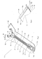
figures 1 and 2 , a fluid-tight slide fastener is shown, in accordance with one embodiment of the present invention and globally indicated with 10. - The
slide fastener 10 comprises a pair oftapes 12, substantially parallel to each other, thetapes 12 being delimited by respective inner and outerlong edges 13a, the innerlong edges 13a facing to each other, and opposite upper and lowershort edges 13b. - Each
tape 12 is equipped with aset 20 of alignedteeth 21 on a central portion of the innerlong edge 13a thereof, in a conventional manner, for example through die-casting or injection molding processes. - In particular, the aligned
teeth 21 of saidsets 20 face each other and are associated withopposite opening stop 24 and closingstop 26. Aslider 22 is slidable between theopening stop 24 and theclosing stop 26 for engaging in a fluid-tight way or disengaging of alignedteeth 21 of saidsets 20 respectively as it will explained better later on in the present description. In particular, theslider 22 stops its opening stroke at theopening stop 24, so disengaging thealigned teeth 21 of saidsets 20 whereas theslider 22 stops its closing stroke at theclosing stop 26 so engaging in a fluid-tight way thealigned teeth 21 of saidsets 20. - In the
figures 1 and 2 , theopening stop 24 is in form of a one single piece applied on both thetapes 12 at the lower ends of thesets 20 of alignedteeth 21, whereas theclosing stop 26 comprises two half-portions, each half-portion being applied on arespective tape 12 at the upper end of therespective set 20 of alignedteeth 21. - The application of the
opening stop 24 and theclosing stop 26 to thetapes 12 can be carried out in a per se conventional manner for example through die casting or injection molding. - Furthermore, the
tapes 12 are joined in a fluid-tight way along at aportion 25 of the respective inner long edges from thesets 20 of alignedteeth 21 and comprising theopening stop 24. In particular, with reference tofigure 1 and4 , on the external side of the slide fastener 10 (the external side being in use the side that is exposed to fluids) theportion 25 extends from the lower ends of saidsets 20 of alignedteeth 21 up to the lowershort edges 13b of the tapes. - As shown in
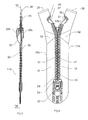
figure 2 , eachtape 12 comprises atextile material strip 14 coated with a fluid barrier material. The coating of thestrips 14 is carried out by fully covering with a fluid-barrier material a strip of textile material forming thetapes 12 and equipped with a plurality ofsets 20 of alignedteeth 21 at one of its longitudinal edges and then transversally heat cutting said coated strip forming thetapes 12. As a result, in eachtape 12, thestrip 14 is coated at thelong edges 13a, at the two opposing faces by respective fluid barrier layers, 16 and 18 and at at least one of itsshort edges 13b (i.e. the short edges formed by the cutting) by aseal 40 resulting from the sealing or welding of thefluid barrier layers figure 2 , thefluid barrier layers short edge 13b of thetape 12 so forming acompact seal 40 of fluid-barrier material which covers the textile material of thestrip 14 in a fluid-tight way at saidshort edge 13b. This result can be obtained both by heat cutting a coated strip forming thetapes 12, for example through a heated blade, and by heat pressing uncoated short edges oftapes 12 after having formed thetapes 12 by cutting in a conventional way (i.e. without heat) a strip formingsaid tapes 12. - In this way, during use of the slide fastener 10, the fluids, in particular water, are prevented from seeping in the
textile material strips 14 through theshort edges 13b of thetapes 12. - The textile material of the
strip 14 may be any woven fabric or not woven fabric of natural or synthetic fibers such as for example polyester. - The fluid-barrier material constituting the coating of the
strip 14 may be any material suitable to provide a fluid-tight seal for thestrip 14. A not limitative example of such a fluid barrier material includes polyurethane. - Each
tape 12 is intended to be joined in a fluid-tight way to the material of a suit/garment (not shown in the figures), at the outerlong edge 13a and the lowershort edge 13b thereof. - This joining is generally carried out in a conventional way, for example by seaming the tapes at their inner side to a corresponding inner fabric layer of the garment and by heat welding the tapes at their outer side to the inner side of an outer fluid-barrier layer of the garment after having interposed a strip of heat-weldable material between said tapes and outer fluid-barrier layer.
- With reference now to
figures 3-8 , a second embodiment of a fluid-tight slide fastener according to the present invention, globally indicated with 110, is now described. - In the
slide fastener 110, elements structurally and/or functionally equivalent to those of theslide fastener 10 are indicated with the same reference numerals, and the description thereof is not repeated. - The
slide fastener 110 substantially differs from theslide fastener 10 described above in that eachtape 12 is obtained from an original strip formingsaid tapes 12 with uppershort edges 13b being uncoated with fluid-barrier material of fluid-barrier layers caps 28, structurally and functionally identical, are applied in a fluid-tight way to arespective tape 12 at the uppershort edge 13b thereof, i.e. theshort edge 13b proximate to therelative closing stop 26, to fully cover thetextile material strip 14 in correspondence with the uppershort edges 13b of thetapes 12. - In more detail, the
cap 28 has a substantially "C" shape comprising twoend portions fluid barrier layers short edge 13b, and anintermediate portion 30c covering said uppershort edge 13b. - In this way, during use of the
slide fastener 110, the fluids, in particular water, are advantageously prevented from seeping in thetextile material strips 14 through the uppershort edges 13b of thetapes 12. - Preferably, each
cap 28 is made of a fluid-barrier plastic material and in particular it is of the same material forming the fluid-barrier layers strip 14. Alternatively, eachcap 28 is made of a fluid-barrier plastic material compatible with material forming the fluid-barrier layers - The application of the
caps 28 to thetapes 14 at theshort edges 13b can be carried out in a conventional manner, for example through plastic material injection processes or gluing. - In addition, it should be noticed that although the
caps 28 are shown applied on thetapes 14 at theirupper edges 13b, as in thefigures 3-8 , they can be applied alternatively at the lowershort edges 13b or at both the upper and lowershort edges 13b as well. In particular, this latter alternative can be practiced on so-called open-ends fasteners, i.e. slide fasteners that are joined to a garment or suit only at the outerlong edges 13a of thetapes 12 so as to cover in a fluid-tight way both the upper and lowershort edges 13b. - With reference now to
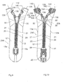
figures 9 and 10 a third embodiment of a fluid-tight slide fastener according to the present invention, globally indicated with 210, is now described. In theslide fastener 210, elements structurally and/or functionally equivalent to those of both theslide fastener 10 and theslide fastener 110 are indicated with the same reference numerals, and the description thereof is not repeated. - As in the
slide fastener 110 described above, theslide fastener 210 has twotapes 12 formed with uppershort edges 13b being uncoated with fluid-barrier material of fluid-barrier layers - In addition, the
slide fastener 210 has twocaps 128, structurally and functionally identical, which are applied in a fluid-tight way to arespective tape 12 at the uppershort edge 13b thereof, i.e. theshort edge 13b proximate to therelative closing stop 26, to fully cover thetextile material strip 14 in correspondence with the uppershort edges 13b of thetapes 12. - In particular, in this embodiment, the two
caps 128 are formed integral with respective half-portions of theclosing stop 126, and are connected to thetapes 12 in a conventional manner for example through die casting or injection molding. In more detail, eachcap 128 comprises aexternal plate 136 and ainternal plate 138, which cover the corresponding end portion of the two fluid barrier layers 16 and 18 of therespective tape 12 at its uppershort edge 13b and thetextile material strip 14 of therespective tape 12 at said uppershort edge 13b Slits 140 are provided on theexternal plate 136, in order to make easier the association of thecap 128 with the externalfluid barrier layer 16. In the example illustrated, theexternal plate 136 is wider than theinternal plate 138, in order to make easier the positioning of thecap 128 during the manufacturing process of theslide fastener 210. - Moreover, each
cap 128 also covers anend portion 142 of the innerlong edge 13a of therespective tape 12 joining to therelative closing stop 126. Preferably, saidend portion 142 of the innerlong edge 13a has a rounded shape, in order to make theslide fastener 210 more ergonomic. - Details of the slider and closing stop, in accordance with the invention, are now described with reference to the
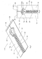
Figs. 3 to 8 , but are applicable to all the above referred embodiments of a slide fastener. - The slider 22 (
Figs. 5-6 ) has anexternal plate 23b (to be associated with a puller - not illustrated -) and aninternal plate 23c embracing together saidsets 20 of aligned teeth, and amiddle portion 23a of substantially wedge-shaped cross section, positioned between saidexternal plate 23b and saidinternal plate 23c. In addition, each half-portion of theclosing stop 26 has a respective substantially half wedge-shapedrecess 27 at the innerlong edges 13a of the tapes so that the half-portions of saidclosing stop 26 form together ahousing 27a (Fig. 8 ) having dimensions at least matching the dimensions ofmiddle portion 23a of theslider 22 when theslider 22 stops in its closing stroke. - As a result, when the
slider 22 is closing (seefigure 6 ), the twosets 20 of aligned teeth are guided by theslider 22 against the two opposed sides of the wedge, until the twosets 20 of aligned teeth mesh at the vertex of the wedge. At the same time, thetapes 14 are normally divaricated at the portions downwards the slider 22 (i.e. toward the closing stop 26) so that folds 32 are normally formed upstream the slider 22 (i.e. where theteeth 21 have been already engaged). - When the
slider 22 approaches its closing stroke (seefigure 8 ), the half-portions of the closing stops 26 are guided by theexternal plate 23b and theinternal plate 23c to close each other so gradually forming thehousing 27a in which the wedge-shapedmiddle portion 23a of theslider 22 will be housed at the time theslider 22 stops in its closing stroke. - In this manner, as shown in
figures 7 and 8 , the twotapes 12 are planar when theslider 22 reaches theclosing stop 26, i.e. the above folds 32, that are formed on eachtape 12 while theslider 22 is moved in its stroke (figures 3 and6 ), disappears when theslider 22 reaches theclosing stop 26. - This is advantageous as it is possible to precisely, easily and efficaciously join the two
tapes 12 of theslide fastener 110 in a fluid-tight way to the material of a suit/garment. On the contrary, in the slide fasteners according to the prior art, folds on the tapes are still existing even when the slider reaches its closing stop so rendering the joining of the tapes to the material of a suit/garment difficult to achieve in a reliable way. - In addition, when the
slider 22 reaches its closing stroke, the free end portions of the innerlong edges 13a of the tapes 12 (i.e. the portions of the inner long edges above theclosing stop 26 along which the tapes are not joined either directly or through theassembly slider 22/teeth 21) are in close contact to each other so preserving the fluid-tight requirements of theslide fastener 110 at said free portions of inner long edges 13. - The slide fastener according to the invention can be manufactured in a simple manner and at reduced costs. In this regard, it should be noticed that the operation of heat-cutting the strips forming the tapes or as an alternative the operation of heat-pressing the uncoated edges of the already formed tapes can be easily integrated in all known manufacturing processes of slide fasteners.
- Thanks to the peculiar construction of the slider and the closing stop which does not allow formation of folds at the tapes, such tapes are always planar to each other and the free portions of their inner long edges are in close contact when the slider is in its closing stroke. As a result, the slide fastener can be joined to the suit/garment in a easier and reliable manner and the fluid-tight requirements of the slide fastener are preserved at the free portions of inner long edges of the tapes.
- A further advantage of the slide fastener according the present invention, in comparison with the prior art, lies in that it allows to save a part of the tape necessary to obtain a predetermined length slide fastener.
Claims (2)
- A fluid-tight slide fastener (10; 110; 210) comprising a pair of tapes (12) both delimited by two opposite long edges (13a) and by two opposite short edges (13b), each tape (12) comprising a textile material strip (14) coated with a fluid barrier material layer (16, 18) at least at the opposite faces thereof, each tape (12) being equipped with a set (20) of aligned teeth (21) on at least a portion of one of said long sides (13a) thereof, the aligned teeth (21) of said sets (20) facing each other and being associated with opposite opening and closing stops (24, 26), and a slider (22) slidable between said closing stop (26) and said opening stop (24) for engaging in a fluid-tight way or disengaging said aligned teeth (21) respectively, characterized in that:the slider (22) has an external plate (23b) and an internal plate (23c) embracing together said sets (20) of aligned teeth (21), and a middle portion (23a) of substantially wedge-shaped cross section positioned between said external plate (23b) and said internal plate (23c), and in that each half-portion of said closing stop (26) has a respective substantially half wedge-shaped recess (27) so that the half-portions of said closing stop (26) form together a housing (27a) having dimensions at least matching the dimensions of middle portion (23a) of the slider (22) when the slider (22) stops in its closing stroke.
- A closing stop (26) for a fluid-tight slide fastener according to claim 1, characterized in that it consists of two half-portions facing each other applied each on a respective tape (12), each half-portion having a respective substantially half wedge-shaped recess (27) so that said half-portions form together a housing (27a) having dimensions at least matching the dimensions of the wedge-shaped middle portion (23a) of the slider (22) of the slide fastener when the slider (22) stops in its closing stroke.
Applications Claiming Priority (2)
| Application Number | Priority Date | Filing Date | Title |
|---|---|---|---|
| US11/278,500 US7392572B2 (en) | 2006-04-03 | 2006-04-03 | Fluidtight slide fastener |
| EP06008458A EP1842445A1 (en) | 2006-04-03 | 2006-04-25 | Fluidtight slide fastener |
Related Parent Applications (2)
| Application Number | Title | Priority Date | Filing Date |
|---|---|---|---|
| EP06008458A Division EP1842445A1 (en) | 2006-04-03 | 2006-04-25 | Fluidtight slide fastener |
| EP06008458.9 Division | 2006-04-25 |
Publications (3)
| Publication Number | Publication Date |
|---|---|
| EP2016849A2 true EP2016849A2 (en) | 2009-01-21 |
| EP2016849A3 EP2016849A3 (en) | 2010-11-03 |
| EP2016849B1 EP2016849B1 (en) | 2012-09-12 |
Family
ID=38115945
Family Applications (2)
| Application Number | Title | Priority Date | Filing Date |
|---|---|---|---|
| EP06008458A Withdrawn EP1842445A1 (en) | 2006-04-03 | 2006-04-25 | Fluidtight slide fastener |
| EP08017948A Not-in-force EP2016849B1 (en) | 2006-04-03 | 2006-04-25 | Fluidtight slide fastener |
Family Applications Before (1)
| Application Number | Title | Priority Date | Filing Date |
|---|---|---|---|
| EP06008458A Withdrawn EP1842445A1 (en) | 2006-04-03 | 2006-04-25 | Fluidtight slide fastener |
Country Status (7)
| Country | Link |
|---|---|
| US (3) | US7392572B2 (en) |
| EP (2) | EP1842445A1 (en) |
| CN (1) | CN101077239B (en) |
| DK (1) | DK2016849T3 (en) |
| HK (1) | HK1110178A1 (en) |
| NZ (2) | NZ554269A (en) |
| RU (1) | RU2428901C2 (en) |
Families Citing this family (27)
| Publication number | Priority date | Publication date | Assignee | Title |
|---|---|---|---|---|
| JP4628233B2 (en) * | 2005-09-29 | 2011-02-09 | Ykk株式会社 | Top stopper for waterproofing of slide fastener |
| EP1908364A1 (en) * | 2006-10-04 | 2008-04-09 | Riri Group S.A. | A fluid-tight slide fastener |
| EP1908365B1 (en) * | 2006-10-04 | 2013-12-11 | Riri Sa | A fluid-tight slide fastener |
| US20080124008A1 (en) * | 2006-11-19 | 2008-05-29 | Ben Meager | Devices and methods for forming a closure between fabrics and/or other materials |
| JP4689631B2 (en) * | 2007-02-08 | 2011-05-25 | Ykk株式会社 | Liquid-tight slide fastener and method for producing liquid-tight slide fastener |
| ES2361341T3 (en) * | 2007-05-16 | 2011-06-16 | Riri Sa | FLUID WRAPPED ZIPPER. |
| CN101754629B (en) * | 2008-12-19 | 2012-08-29 | 群康科技(深圳)有限公司 | Circuit board fixing structure |
| CN102665475B (en) * | 2009-12-25 | 2015-08-19 | Ykk株式会社 | Slide fastener |
| GB2492714A (en) * | 2010-04-09 | 2013-01-09 | Lion Apparel Inc | Vapour resistant closure |
| TWI486134B (en) * | 2011-03-18 | 2015-06-01 | Columbia Sportswear Na Inc | A zipper assembly with an adhesive zipper tape |
| KR101331733B1 (en) * | 2011-08-16 | 2013-11-20 | 이병우 | Pest-resistant protection unit and zipper device |
| CN104053378B (en) | 2012-01-30 | 2016-11-16 | Ykk株式会社 | Water proofing property slide fastener |
| GB201311761D0 (en) | 2013-07-01 | 2013-08-14 | Raw Ip Ltd | A zip fastener |
| US9944028B1 (en) | 2013-10-24 | 2018-04-17 | Ideal Fastener Corporation | Methods for manufacturing slide fastener with overmolded components |
| US9538817B2 (en) * | 2014-07-22 | 2017-01-10 | Ykk Corporation | Sealing for open-end slide fastener |
| CN104146445B (en) * | 2014-08-15 | 2016-08-24 | 垦青(浙江)拉链有限公司 | Prevent stopping and use this anti-separating zipper stopped under water under water |
| US20160081437A1 (en) * | 2014-09-24 | 2016-03-24 | Ideal Fastener Corporation | Breakaway slide fastener for large-scale applications and methods for using same |
| ES2780201T3 (en) | 2014-12-04 | 2020-08-24 | Nite Ize Inc | Systems for improved rack slider terminal |
| US11109650B2 (en) * | 2014-12-04 | 2021-09-07 | Nite Ize, Inc. | Systems and methods for improved zipper slider garage |
| GB201520349D0 (en) * | 2015-11-18 | 2015-12-30 | Ykk Europ Ltd And Ykk Corp | Slide fastener and method of preparation |
| TWI566715B (en) * | 2016-03-17 | 2017-01-21 | 冠宇拉鍊股份有限公司 | Method for manufacturing a watertight zipper |
| CN109068814B (en) * | 2016-05-06 | 2021-04-09 | Ykk株式会社 | Fastener element, device for manufacturing fastener element, and method for manufacturing fastener element |
| US10531712B2 (en) | 2016-10-03 | 2020-01-14 | Ykk Corporation | Sealing for open-end slide fasteners |
| RU178583U1 (en) * | 2017-09-15 | 2018-04-11 | Общество с ограниченной ответственностью "Гамма" | HIDDEN ZIP |
| TWI635821B (en) * | 2017-11-13 | 2018-09-21 | 冠宇拉鍊股份有限公司 | Watertight zipper |
| US11363860B2 (en) | 2019-11-23 | 2022-06-21 | Talon Technologies, Inc. | Waterproof curved zippers |
| JP2023503233A (en) | 2019-11-23 | 2023-01-27 | タロン テクノロジーズ、インコーポレイティッド | curved zipper |
Citations (5)
| Publication number | Priority date | Publication date | Assignee | Title |
|---|---|---|---|---|
| GB631265A (en) * | 1946-04-10 | 1949-10-31 | Harvey Ladew Williams | Water-tight fastener |
| GB650599A (en) * | 1948-09-24 | 1951-02-28 | Long & Hambly Ltd | Improvements in or relating to means for releasably joining flexible members |
| EP0095160A1 (en) * | 1982-05-26 | 1983-11-30 | Yoshida Kogyo K.K. | Watertight slide fastener |
| FR2608904A1 (en) * | 1986-12-26 | 1988-07-01 | Yoshida Kogyo Kk | UPPER STOP FOR WATERPROOF ZIPPER CLOSURE |
| EP0522366A1 (en) * | 1991-06-28 | 1993-01-13 | Ykk Corporation | Watertight slide fastener |
Family Cites Families (21)
| Publication number | Priority date | Publication date | Assignee | Title |
|---|---|---|---|---|
| US3490109A (en) * | 1966-07-06 | 1970-01-20 | Opti Holding Ag | Fluidtight slide fastener |
| DE1928691A1 (en) * | 1969-06-06 | 1971-03-25 | Opti Holding Ag | Divisible zipper |
| JPS4915548A (en) * | 1972-06-05 | 1974-02-12 | ||
| US4001922A (en) * | 1975-11-03 | 1977-01-11 | Textron, Inc. | Tape reinforcements for slide fasteners |
| JPS5740805Y2 (en) * | 1978-02-21 | 1982-09-08 | ||
| US4233099A (en) * | 1978-12-20 | 1980-11-11 | Textron Inc. | Slide fastener method of manufacture |
| AU545352B2 (en) * | 1982-05-19 | 1985-07-11 | Yoshida Kogyo K.K. | Slide fastener stringer |
| JPS6175712U (en) * | 1984-10-25 | 1986-05-22 | ||
| JPS6368103A (en) * | 1986-09-09 | 1988-03-28 | ワイケイケイ株式会社 | Slide fastener equipped with separating and inlay jig |
| JPH084525B2 (en) * | 1987-04-25 | 1996-01-24 | ワイケイケイ株式会社 | Top stopper attachment device for slide fastener |
| JPH0759204B2 (en) | 1988-06-10 | 1995-06-28 | ワイケイケイ株式会社 | Waterproof slide fastener with separable bottom end stop |
| DE19643861C2 (en) * | 1996-10-30 | 1999-05-20 | Hartmut Ortlieb | Process for making a water and gas tight zipper |
| US6105214A (en) * | 1998-09-25 | 2000-08-22 | Press; Stuart | Water resistant slide fastener and process for preparing same |
| JP3580725B2 (en) * | 1999-04-30 | 2004-10-27 | Ykk株式会社 | Method for manufacturing waterproof slide fastener |
| US6070306A (en) * | 1999-11-19 | 2000-06-06 | Wang; Wallace | Stop and zipper teeth arrangement |
| RO121002B1 (en) * | 2000-07-11 | 2006-11-30 | Riri S.A. | Sealing slide fastener |
| GB0103351D0 (en) * | 2001-02-10 | 2001-03-28 | Reddiplex Group Plc | Slide Fasteners |
| JP3733327B2 (en) * | 2001-12-20 | 2006-01-11 | Ykk株式会社 | Hidden slide fastener opening and closing tool |
| NZ532016A (en) * | 2002-06-25 | 2005-09-30 | Riri S | Method of sealing the join between a zip and a garment with a lining |
| US20040007309A1 (en) * | 2002-07-11 | 2004-01-15 | Kevin Owen | Tack knife |
| TWI220106B (en) * | 2003-05-27 | 2004-08-11 | Sun Yen Ping | Method for producing zipper with waterproof layer lined in the cloth belt and product thereof |
-
2006
- 2006-04-03 US US11/278,500 patent/US7392572B2/en not_active Expired - Fee Related
- 2006-04-25 DK DK08017948.4T patent/DK2016849T3/en active
- 2006-04-25 EP EP06008458A patent/EP1842445A1/en not_active Withdrawn
- 2006-04-25 EP EP08017948A patent/EP2016849B1/en not_active Not-in-force
-
2007
- 2007-04-02 NZ NZ554269A patent/NZ554269A/en not_active IP Right Cessation
- 2007-04-02 NZ NZ568641A patent/NZ568641A/en not_active IP Right Cessation
- 2007-04-03 RU RU2007112229/12A patent/RU2428901C2/en not_active IP Right Cessation
- 2007-04-03 CN CN200710129209.8A patent/CN101077239B/en not_active Expired - Fee Related
- 2007-11-19 US US11/942,296 patent/US7568270B2/en not_active Expired - Fee Related
-
2008
- 2008-04-29 HK HK08104755.9A patent/HK1110178A1/en not_active IP Right Cessation
-
2009
- 2009-06-30 US US12/494,464 patent/US7934305B2/en not_active Expired - Fee Related
Patent Citations (5)
| Publication number | Priority date | Publication date | Assignee | Title |
|---|---|---|---|---|
| GB631265A (en) * | 1946-04-10 | 1949-10-31 | Harvey Ladew Williams | Water-tight fastener |
| GB650599A (en) * | 1948-09-24 | 1951-02-28 | Long & Hambly Ltd | Improvements in or relating to means for releasably joining flexible members |
| EP0095160A1 (en) * | 1982-05-26 | 1983-11-30 | Yoshida Kogyo K.K. | Watertight slide fastener |
| FR2608904A1 (en) * | 1986-12-26 | 1988-07-01 | Yoshida Kogyo Kk | UPPER STOP FOR WATERPROOF ZIPPER CLOSURE |
| EP0522366A1 (en) * | 1991-06-28 | 1993-01-13 | Ykk Corporation | Watertight slide fastener |
Also Published As
| Publication number | Publication date |
|---|---|
| US7568270B2 (en) | 2009-08-04 |
| US20080115341A1 (en) | 2008-05-22 |
| US7392572B2 (en) | 2008-07-01 |
| NZ568641A (en) | 2009-09-25 |
| US20090282665A1 (en) | 2009-11-19 |
| EP1842445A1 (en) | 2007-10-10 |
| DK2016849T3 (en) | 2012-12-03 |
| CN101077239B (en) | 2011-05-18 |
| US20070226965A1 (en) | 2007-10-04 |
| NZ554269A (en) | 2008-07-31 |
| CN101077239A (en) | 2007-11-28 |
| US7934305B2 (en) | 2011-05-03 |
| RU2428901C2 (en) | 2011-09-20 |
| EP2016849B1 (en) | 2012-09-12 |
| HK1110178A1 (en) | 2008-07-11 |
| RU2007112229A (en) | 2008-10-20 |
| EP2016849A3 (en) | 2010-11-03 |
Similar Documents
| Publication | Publication Date | Title |
|---|---|---|
| EP2016849B1 (en) | Fluidtight slide fastener | |
| US7708464B2 (en) | Deaeration valve and compression bag equipped therewith | |
| TWI584756B (en) | Slide fastener | |
| CN104223608B (en) | The manufacturing method of a part for slide fastener | |
| JP5690118B2 (en) | Slide fastener | |
| US20120318702A1 (en) | Vacuum packing bag | |
| US8419278B2 (en) | Check valve and compression bag and air cushion bag equipped therewith | |
| JP2008206986A6 (en) | Zip fastener stop | |
| CA2583960C (en) | Fluidtight slide fastener | |
| WO2012165453A1 (en) | Method for heat sealing zipper tape, method for manufacturing film roll having zipper tape, and method for manufacturing packaging having zipper tape | |
| TWI816156B (en) | Slide fastener chain and slide fastener | |
| JP4761408B1 (en) | Check valve and storage body provided with the same | |
| FI69958C (en) | TILLSLUTNINGSBANDPRODUKT OCH FOERFARANDE FOER TILLVERKNING AV DENSAMMA | |
| JPH01153829A (en) | Gas bag composed of connectively provided independent gas chambers | |
| EP1481601B1 (en) | Closure for Zipper Ends | |
| JPH052588B2 (en) | ||
| WO2013136473A1 (en) | Waterproof slide fastener and waterproof product | |
| KR200320850Y1 (en) | Waterproof zipper | |
| JPH09290840A (en) | Synthetic resin bag body with check valve | |
| KR200478370Y1 (en) | Waterproof, anti-split, high transverse tensile strength double-layer zipper and its fabrication method | |
| JPH0849163A (en) | Frayproofing processing method for flexible container material |
Legal Events
| Date | Code | Title | Description |
|---|---|---|---|
| PUAI | Public reference made under article 153(3) epc to a published international application that has entered the european phase |
Free format text: ORIGINAL CODE: 0009012 |
|
| AC | Divisional application: reference to earlier application |
Ref document number: 1842445 Country of ref document: EP Kind code of ref document: P |
|
| AK | Designated contracting states |
Kind code of ref document: A2 Designated state(s): AT BE BG CH CY CZ DE DK EE ES FI FR GB GR HU IE IS IT LI LT LU LV MC NL PL PT RO SE SI SK TR |
|
| PUAL | Search report despatched |
Free format text: ORIGINAL CODE: 0009013 |
|
| AK | Designated contracting states |
Kind code of ref document: A3 Designated state(s): AT BE BG CH CY CZ DE DK EE ES FI FR GB GR HU IE IS IT LI LT LU LV MC NL PL PT RO SE SI SK TR |
|
| RIC1 | Information provided on ipc code assigned before grant |
Ipc: A44B 19/32 20060101AFI20081127BHEP |
|
| 17P | Request for examination filed |
Effective date: 20110428 |
|
| AKX | Designation fees paid |
Designated state(s): AT BE BG CH CY CZ DE DK EE ES FI FR GB GR HU IE IS IT LI LT LU LV MC NL PL PT RO SE SI SK TR |
|
| REG | Reference to a national code |
Ref country code: DE Ref legal event code: R079 Ref document number: 602006032007 Country of ref document: DE Free format text: PREVIOUS MAIN CLASS: A44B0019320000 Ipc: A44B0019380000 |
|
| RIC1 | Information provided on ipc code assigned before grant |
Ipc: A44B 19/38 20060101AFI20120430BHEP Ipc: A44B 19/32 20060101ALI20120430BHEP Ipc: A44B 19/60 20060101ALI20120430BHEP |
|
| GRAP | Despatch of communication of intention to grant a patent |
Free format text: ORIGINAL CODE: EPIDOSNIGR1 |
|
| GRAS | Grant fee paid |
Free format text: ORIGINAL CODE: EPIDOSNIGR3 |
|
| GRAA | (expected) grant |
Free format text: ORIGINAL CODE: 0009210 |
|
| RAP1 | Party data changed (applicant data changed or rights of an application transferred) |
Owner name: RIRI SA |
|
| RIN1 | Information on inventor provided before grant (corrected) |
Inventor name: COSSUTTI, LIVIO |
|
| AC | Divisional application: reference to earlier application |
Ref document number: 1842445 Country of ref document: EP Kind code of ref document: P |
|
| AK | Designated contracting states |
Kind code of ref document: B1 Designated state(s): AT BE BG CH CY CZ DE DK EE ES FI FR GB GR HU IE IS IT LI LT LU LV MC NL PL PT RO SE SI SK TR |
|
| REG | Reference to a national code |
Ref country code: GB Ref legal event code: FG4D |
|
| REG | Reference to a national code |
Ref country code: CH Ref legal event code: EP |
|
| REG | Reference to a national code |
Ref country code: AT Ref legal event code: REF Ref document number: 574632 Country of ref document: AT Kind code of ref document: T Effective date: 20120915 |
|
| REG | Reference to a national code |
Ref country code: IE Ref legal event code: FG4D |
|
| REG | Reference to a national code |
Ref country code: CH Ref legal event code: NV Representative=s name: ING. MARCO ZARDI C/O M. ZARDI & CO. S.A. |
|
| REG | Reference to a national code |
Ref country code: DE Ref legal event code: R096 Ref document number: 602006032007 Country of ref document: DE Effective date: 20121108 |
|
| REG | Reference to a national code |
Ref country code: DK Ref legal event code: T3 |
|
| REG | Reference to a national code |
Ref country code: SE Ref legal event code: TRGR |
|
| PG25 | Lapsed in a contracting state [announced via postgrant information from national office to epo] |
Ref country code: CY Free format text: LAPSE BECAUSE OF FAILURE TO SUBMIT A TRANSLATION OF THE DESCRIPTION OR TO PAY THE FEE WITHIN THE PRESCRIBED TIME-LIMIT Effective date: 20120912 Ref country code: LT Free format text: LAPSE BECAUSE OF FAILURE TO SUBMIT A TRANSLATION OF THE DESCRIPTION OR TO PAY THE FEE WITHIN THE PRESCRIBED TIME-LIMIT Effective date: 20120912 |
|
| REG | Reference to a national code |
Ref country code: NL Ref legal event code: VDEP Effective date: 20120912 |
|
| REG | Reference to a national code |
Ref country code: AT Ref legal event code: MK05 Ref document number: 574632 Country of ref document: AT Kind code of ref document: T Effective date: 20120912 |
|
| REG | Reference to a national code |
Ref country code: LT Ref legal event code: MG4D Effective date: 20120926 |
|
| PG25 | Lapsed in a contracting state [announced via postgrant information from national office to epo] |
Ref country code: LV Free format text: LAPSE BECAUSE OF FAILURE TO SUBMIT A TRANSLATION OF THE DESCRIPTION OR TO PAY THE FEE WITHIN THE PRESCRIBED TIME-LIMIT Effective date: 20120912 Ref country code: GR Free format text: LAPSE BECAUSE OF FAILURE TO SUBMIT A TRANSLATION OF THE DESCRIPTION OR TO PAY THE FEE WITHIN THE PRESCRIBED TIME-LIMIT Effective date: 20121213 Ref country code: SI Free format text: LAPSE BECAUSE OF FAILURE TO SUBMIT A TRANSLATION OF THE DESCRIPTION OR TO PAY THE FEE WITHIN THE PRESCRIBED TIME-LIMIT Effective date: 20120912 |
|
| PG25 | Lapsed in a contracting state [announced via postgrant information from national office to epo] |
Ref country code: CZ Free format text: LAPSE BECAUSE OF FAILURE TO SUBMIT A TRANSLATION OF THE DESCRIPTION OR TO PAY THE FEE WITHIN THE PRESCRIBED TIME-LIMIT Effective date: 20120912 Ref country code: BE Free format text: LAPSE BECAUSE OF FAILURE TO SUBMIT A TRANSLATION OF THE DESCRIPTION OR TO PAY THE FEE WITHIN THE PRESCRIBED TIME-LIMIT Effective date: 20120912 Ref country code: RO Free format text: LAPSE BECAUSE OF FAILURE TO SUBMIT A TRANSLATION OF THE DESCRIPTION OR TO PAY THE FEE WITHIN THE PRESCRIBED TIME-LIMIT Effective date: 20120912 Ref country code: ES Free format text: LAPSE BECAUSE OF FAILURE TO SUBMIT A TRANSLATION OF THE DESCRIPTION OR TO PAY THE FEE WITHIN THE PRESCRIBED TIME-LIMIT Effective date: 20121223 Ref country code: NL Free format text: LAPSE BECAUSE OF FAILURE TO SUBMIT A TRANSLATION OF THE DESCRIPTION OR TO PAY THE FEE WITHIN THE PRESCRIBED TIME-LIMIT Effective date: 20120912 Ref country code: IS Free format text: LAPSE BECAUSE OF FAILURE TO SUBMIT A TRANSLATION OF THE DESCRIPTION OR TO PAY THE FEE WITHIN THE PRESCRIBED TIME-LIMIT Effective date: 20130112 Ref country code: EE Free format text: LAPSE BECAUSE OF FAILURE TO SUBMIT A TRANSLATION OF THE DESCRIPTION OR TO PAY THE FEE WITHIN THE PRESCRIBED TIME-LIMIT Effective date: 20120912 |
|
| PG25 | Lapsed in a contracting state [announced via postgrant information from national office to epo] |
Ref country code: PL Free format text: LAPSE BECAUSE OF FAILURE TO SUBMIT A TRANSLATION OF THE DESCRIPTION OR TO PAY THE FEE WITHIN THE PRESCRIBED TIME-LIMIT Effective date: 20120912 Ref country code: SK Free format text: LAPSE BECAUSE OF FAILURE TO SUBMIT A TRANSLATION OF THE DESCRIPTION OR TO PAY THE FEE WITHIN THE PRESCRIBED TIME-LIMIT Effective date: 20120912 Ref country code: PT Free format text: LAPSE BECAUSE OF FAILURE TO SUBMIT A TRANSLATION OF THE DESCRIPTION OR TO PAY THE FEE WITHIN THE PRESCRIBED TIME-LIMIT Effective date: 20130114 |
|
| PG25 | Lapsed in a contracting state [announced via postgrant information from national office to epo] |
Ref country code: AT Free format text: LAPSE BECAUSE OF FAILURE TO SUBMIT A TRANSLATION OF THE DESCRIPTION OR TO PAY THE FEE WITHIN THE PRESCRIBED TIME-LIMIT Effective date: 20120912 |
|
| PLBE | No opposition filed within time limit |
Free format text: ORIGINAL CODE: 0009261 |
|
| STAA | Information on the status of an ep patent application or granted ep patent |
Free format text: STATUS: NO OPPOSITION FILED WITHIN TIME LIMIT |
|
| PG25 | Lapsed in a contracting state [announced via postgrant information from national office to epo] |
Ref country code: BG Free format text: LAPSE BECAUSE OF FAILURE TO SUBMIT A TRANSLATION OF THE DESCRIPTION OR TO PAY THE FEE WITHIN THE PRESCRIBED TIME-LIMIT Effective date: 20121212 |
|
| 26N | No opposition filed |
Effective date: 20130613 |
|
| REG | Reference to a national code |
Ref country code: DE Ref legal event code: R097 Ref document number: 602006032007 Country of ref document: DE Effective date: 20130613 |
|
| PG25 | Lapsed in a contracting state [announced via postgrant information from national office to epo] |
Ref country code: MC Free format text: LAPSE BECAUSE OF FAILURE TO SUBMIT A TRANSLATION OF THE DESCRIPTION OR TO PAY THE FEE WITHIN THE PRESCRIBED TIME-LIMIT Effective date: 20120912 |
|
| REG | Reference to a national code |
Ref country code: IE Ref legal event code: MM4A |
|
| PG25 | Lapsed in a contracting state [announced via postgrant information from national office to epo] |
Ref country code: IE Free format text: LAPSE BECAUSE OF NON-PAYMENT OF DUE FEES Effective date: 20130425 |
|
| REG | Reference to a national code |
Ref country code: FR Ref legal event code: PLFP Year of fee payment: 10 |
|
| PG25 | Lapsed in a contracting state [announced via postgrant information from national office to epo] |
Ref country code: HU Free format text: LAPSE BECAUSE OF FAILURE TO SUBMIT A TRANSLATION OF THE DESCRIPTION OR TO PAY THE FEE WITHIN THE PRESCRIBED TIME-LIMIT; INVALID AB INITIO Effective date: 20060425 Ref country code: LU Free format text: LAPSE BECAUSE OF NON-PAYMENT OF DUE FEES Effective date: 20130425 |
|
| PGFP | Annual fee paid to national office [announced via postgrant information from national office to epo] |
Ref country code: GB Payment date: 20150424 Year of fee payment: 10 Ref country code: DK Payment date: 20150422 Year of fee payment: 10 Ref country code: DE Payment date: 20150422 Year of fee payment: 10 Ref country code: TR Payment date: 20150422 Year of fee payment: 10 Ref country code: FI Payment date: 20150422 Year of fee payment: 10 Ref country code: SE Payment date: 20150424 Year of fee payment: 10 Ref country code: CH Payment date: 20150421 Year of fee payment: 10 |
|
| PGFP | Annual fee paid to national office [announced via postgrant information from national office to epo] |
Ref country code: FR Payment date: 20150422 Year of fee payment: 10 Ref country code: IT Payment date: 20150427 Year of fee payment: 10 |
|
| REG | Reference to a national code |
Ref country code: DE Ref legal event code: R119 Ref document number: 602006032007 Country of ref document: DE |
|
| REG | Reference to a national code |
Ref country code: DK Ref legal event code: EBP Effective date: 20160430 |
|
| REG | Reference to a national code |
Ref country code: SE Ref legal event code: EUG |
|
| REG | Reference to a national code |
Ref country code: CH Ref legal event code: PL |
|
| GBPC | Gb: european patent ceased through non-payment of renewal fee |
Effective date: 20160425 |
|
| REG | Reference to a national code |
Ref country code: FR Ref legal event code: ST Effective date: 20161230 |
|
| PG25 | Lapsed in a contracting state [announced via postgrant information from national office to epo] |
Ref country code: GB Free format text: LAPSE BECAUSE OF NON-PAYMENT OF DUE FEES Effective date: 20160425 Ref country code: FR Free format text: LAPSE BECAUSE OF NON-PAYMENT OF DUE FEES Effective date: 20160502 Ref country code: CH Free format text: LAPSE BECAUSE OF NON-PAYMENT OF DUE FEES Effective date: 20160430 Ref country code: FI Free format text: LAPSE BECAUSE OF NON-PAYMENT OF DUE FEES Effective date: 20160425 Ref country code: DE Free format text: LAPSE BECAUSE OF NON-PAYMENT OF DUE FEES Effective date: 20161101 Ref country code: LI Free format text: LAPSE BECAUSE OF NON-PAYMENT OF DUE FEES Effective date: 20160430 |
|
| PG25 | Lapsed in a contracting state [announced via postgrant information from national office to epo] |
Ref country code: SE Free format text: LAPSE BECAUSE OF NON-PAYMENT OF DUE FEES Effective date: 20160426 Ref country code: IT Free format text: LAPSE BECAUSE OF NON-PAYMENT OF DUE FEES Effective date: 20160425 |
|
| PG25 | Lapsed in a contracting state [announced via postgrant information from national office to epo] |
Ref country code: DK Free format text: LAPSE BECAUSE OF NON-PAYMENT OF DUE FEES Effective date: 20160430 |
|
| PG25 | Lapsed in a contracting state [announced via postgrant information from national office to epo] |
Ref country code: TR Free format text: LAPSE BECAUSE OF NON-PAYMENT OF DUE FEES Effective date: 20160425 |