EP2016846B1 - Protective helmet - Google Patents
Protective helmet Download PDFInfo
- Publication number
- EP2016846B1 EP2016846B1 EP08158051A EP08158051A EP2016846B1 EP 2016846 B1 EP2016846 B1 EP 2016846B1 EP 08158051 A EP08158051 A EP 08158051A EP 08158051 A EP08158051 A EP 08158051A EP 2016846 B1 EP2016846 B1 EP 2016846B1
- Authority
- EP
- European Patent Office
- Prior art keywords
- absorber
- outer shell
- protective helmet
- arrangement
- absorber arrangement
- Prior art date
- Legal status (The legal status is an assumption and is not a legal conclusion. Google has not performed a legal analysis and makes no representation as to the accuracy of the status listed.)
- Active
Links
Images

Classifications
-
- A—HUMAN NECESSITIES
- A42—HEADWEAR
- A42B—HATS; HEAD COVERINGS
- A42B3/00—Helmets; Helmet covers ; Other protective head coverings
- A42B3/04—Parts, details or accessories of helmets
- A42B3/06—Impact-absorbing shells, e.g. of crash helmets
-
- A—HUMAN NECESSITIES
- A42—HEADWEAR
- A42B—HATS; HEAD COVERINGS
- A42B3/00—Helmets; Helmet covers ; Other protective head coverings
- A42B3/04—Parts, details or accessories of helmets
- A42B3/06—Impact-absorbing shells, e.g. of crash helmets
- A42B3/062—Impact-absorbing shells, e.g. of crash helmets with reinforcing means
- A42B3/063—Impact-absorbing shells, e.g. of crash helmets with reinforcing means using layered structures
- A42B3/064—Impact-absorbing shells, e.g. of crash helmets with reinforcing means using layered structures with relative movement between layers
Definitions
- the invention relates to a protective helmet with a convexly outwardly curved outer shell.
- a safety helmet The main purpose of a safety helmet is to protect a person's head from being injured by impact on the head. Most impacts on the head are made by falling objects. Even at drop heights of more than 5 m even light objects can already have considerable kinetic energy, which cause damage or destruction of the outer shell on impact. A very hard, stable outer shell, which is not destroyed, has the Effect that the impact energy is largely transferred to the head. When the impact energy is absorbed by the interior, the helmet shell can dangerously approach the head.
- the object of the invention is in contrast to provide a protective helmet, which provides better protection against falling objects.
- the helmet according to the invention has in the roof area on the outside of the closed outwardly curved helmet outer shell on a separate absorber arrangement, which is placed on the outer shell from the outside.
- the separate absorber arrangement absorbs large quantities of the kinetic energy of a falling and impacting object from a greater height, especially in the central roof area of the protective helmet.
- the outer shell does not need to absorb appreciable kinetic energy, it can be made very hard and unyielding.
- the outer shell is inclined substantially at an angle of 60 ° and less to the vertical.
- the absorber arrangement is thus arranged substantially in the areas in which the tangential on the outer shell has an angle of 60 ° and more to the vertical.
- the absorber arrangement is plastically deformable.
- the absorber arrangement can in principle also be designed to be elastically deformable, with plastically deformable absorber elements, however, a very high level can be achieved kinetic energy converted into deformation energy and thus reliably absorbed.
- a plastically deformable absorber arrangement represents a simple and inexpensive solution of an absorber that can absorb high absorption energies.
- the absorber arrangement is formed exchangeable.
- the absorber assembly is placed from the outside on the outer shell and fastened with releasable fastening means on the outer shell. Due to the exchangeability of the absorber arrangement, the absorber arrangement can be exchanged if, for example, it is correspondingly deformed after an absorption case. This saves costs and resources.
- the outer shell in its roof area on an absorber trough for receiving the absorber arrangement.
- the absorber arrangement has a certain height.
- the absorber arrangement used in the absorber trough of the outer shell does not protrude at all or only relatively slightly out of the contour of the outer shell.
- the absorber arrangement or the absorber element on the one hand rigid pins and on the other hand torsion sleeves each having interlocking screw structures.
- the torsion sleeves are preferably absorber side and the rigid pins preferably provided on the outer shell side.
- the screw structures are so steep that they show no self-locking behavior.
- the torsion sleeves are pushed axially onto the rigid pins. Due to the interlocking screw structures, the torsion sleeve is forced to rotate during an axial proximal movement which causes a torsion of the cylindrical torsion sleeve entails. As a result, the Torsionshülse is plastically deformed and reduces in this way kinetic energy.
- absorber elements as a torsion and rigid pin a structure is provided which can absorb very high kinetic energy, and which can be programmed constant and accurate in terms of their mechanical behavior even in the long term.
- the absorber arrangement preferably has an absorber plate, wherein the torsion sleeves protrude proximally from the absorber plate.
- the rigid pins are each arranged exactly opposite to the outer shell.
- the absorber assembly and in particular the absorber plate with the torsion sleeves integrally attached thereto, is made of plastic.
- the outer shell with the rigid pins does not have to, but can also be made of plastic.
- all Torsionshülsen and all rigid pins are arranged substantially parallel to each other.
- the Torsionshülsen and rigid pins are substantially perpendicular, based on the supporting position of the attached protective helmet.
- the absorber arrangement thus has a main absorption orientation which is approximately vertical.
- the absorber arrangement and in particular the absorber plate with separate fastening elements, interchangeably attached to the outer shell.
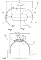
- FIG. 1 In plan view, a protective helmet is shown, as used for example in the construction industry, in forestry and in other areas for the mechanical protection of the head of the wearer.
- the protective helmet 10 has a helmet outer shell 12 made of plastic, a transparent plastic visor 14 and an interior not shown in the interior of the outer shell.
- the outer shell In the roof area, defined by the roof area width and length D x , D y , the outer shell has an absorber trough 16, which is covered by an absorber arrangement 18, which is formed by an absorber element 21.
- the outer shell 12 has in plan view a length H y and a width of H x .
- the absorber element 21 has in plan view a length of D y and a width of D x .
- the length and width D y , D x of the absorber element 21 is approximately 20-40% of the length and width H y , H x of the outer shell 12.
- the angle ⁇ of the outer shell 12 to the vertical in the edge region of the absorber assembly 18 is everywhere at most 60 °.
- the absorber arrangement 18 is essentially formed by an absorber plate 20, absorber-plate-side torsion sleeves 22, which together form the absorber element 21, and outer shell-side rigid pins 24. Both the torsion sleeves 22 and the rigid pins 24 each have interlocking screw structures 26, 28.
- the rigid pin 24 consists of a in Cross-section circular body 30, which may be formed, for example, a hollow cylinder. On the outside of the main body 30, two screw paths 32 are integrally formed.
- the outer diameter S of the rigid pin body is between 3 mm and 15 mm.
- the torsion sleeve 22 consists of a hollow octagonal base body 40.
- the inner diameter S 'of the inner free circle is slightly larger than the outer diameter S of the circular base body 30 of the rigid pin 24.
- the front end of the Torsionshülsen body 40 has two screw paths 42, the slope of the slope the screw paths 32 of the rigid pins 24 corresponds. In the assembled state, the main body 30 of the rigid pin 24 protrudes into the cavity 44 of the torsion sleeve 22, so that both are guided axially relative to one another.
- the absorber arrangement 18 has at the longitudinal ends of the absorber plate 20 clip-like fastening elements 50, with which the absorber element 21 is mounted interchangeably on the outer shell 12.
- the absorber element 21 is formed integrally, including the torsion sleeves 22 and the absorber plate 20.
- the outer shell 12 is integrally formed, including the rigid pins 24.
- absorber assembly 18 is an easy to manufacture and mountable absorber element for absorption by plastically deforming Absorptive elements created. After a deformation of one or more torsion sleeves 22, the absorption element 21 can be easily replaced.
Abstract
Description
Die Erfindung bezieht sich auf einen Schutzhelm mit einer konvex nach außen gewölbten Außenschale.The invention relates to a protective helmet with a convexly outwardly curved outer shell.
Der Hauptzweck eines Schutzhelmes ist der Schutz des Kopfes einer Person vor Verletzungen durch Stöße auf den Kopf. Die meisten Stöße auf den Kopf erfolgen durch herabfallende Gegenstände. Bereits bei Fallhöhen von mehr als 5 m können auch leichte Gegenstände schon erhebliche kinetische Energie aufweisen, die beim Aufprall eine Beschädigung oder Zerstörung der Außenschale bewirken. Eine sehr harte, stabile Außenschale, die dabei nicht zerstört wird, hat die Wirkung, dass die Stoßenergie weitgehend auf den Kopf übertragen wird. Wenn die Stoßenergie durch die Innenausstattung absorbiert wird, kann sich die Helmschale dem Kopf gefährlich annähern.The main purpose of a safety helmet is to protect a person's head from being injured by impact on the head. Most impacts on the head are made by falling objects. Even at drop heights of more than 5 m even light objects can already have considerable kinetic energy, which cause damage or destruction of the outer shell on impact. A very hard, stable outer shell, which is not destroyed, has the Effect that the impact energy is largely transferred to the head. When the impact energy is absorbed by the interior, the helmet shell can dangerously approach the head.
Aufgabe der Erfindung ist es demgegenüber, einen Schutzhelm zu schaffen, der einen besseren Schutz vor herabfallenden Gegenständen gewährt.The object of the invention is in contrast to provide a protective helmet, which provides better protection against falling objects.
Diese Aufgabe wird erfindungsgemäß gelöst mit einem Schutzhelm mit den Merkmalen des Schutzanspruches 1.This object is achieved with a protective helmet with the features of the protection claim. 1
Der erfindungsgemäße Schutzhelm weist im Dachbereich auf der Außenseite der geschlossenen nach außen gewölbten Helm- Außenschale eine separate Absorberanordnung auf, die von außen auf die Außenschale aufgesetzt ist. Die separate Absorberanordnung absorbiert insbesondere im zentralen Dachbereich des Schutzhelmes große Mengen der kinetischen Energie eines aus größerer Höhe herabfallenden und auftreffenden Gegenstandes.The helmet according to the invention has in the roof area on the outside of the closed outwardly curved helmet outer shell on a separate absorber arrangement, which is placed on the outer shell from the outside. The separate absorber arrangement absorbs large quantities of the kinetic energy of a falling and impacting object from a greater height, especially in the central roof area of the protective helmet.
Da die Außenschale keine nennenswerte kinetische Energie absorbieren braucht bzw. soll, kann sie sehr hart und unnachgiebig ausgebildet sein.Since the outer shell does not need to absorb appreciable kinetic energy, it can be made very hard and unyielding.
Bevorzugt ist im Randbereich der Absorberanordnung die Außenschale im Wesentlichen mit einem Winkel von 60° und weniger zur Senkrechten geneigt. Hierdurch wird ein herabfallender Gegenstand zur Seite abgelenkt, so dass im Randbereich keine Absorberanordnung erforderlich ist, um einen verbesserten Schutz vor herabfallenden Gegenständen sicherzustellen. Die Absorberanordnung ist also im Wesentlichen in den Bereichen angeordnet, in denen die Tangentiale auf der Außenschale einen Winkel von 60° und mehr zur Senkrechten aufweist. Erfindungsgemäß ist die Absorberanordnung plastisch verformbar. Zwar kann die Absorberanordnung grundsätzlich auch elastisch verformbar ausgebildet sein, jedoch kann mit plastisch verformbaren Absorberelementen eine sehr hohe kinetische Energie in Verformungsenergie umgewandelt und auf diese Weise zuverlässig absorbiert werden. Eine plastisch verformbare Absorberanordnung stellt eine einfache und preiswerte Lösung eines Absorbers dar, die hohe Absorptionsenergien aufnehmen kann.Preferably, in the edge region of the absorber arrangement, the outer shell is inclined substantially at an angle of 60 ° and less to the vertical. As a result, a falling object is deflected to the side, so that in the edge region no absorber arrangement is required to ensure improved protection against falling objects. The absorber arrangement is thus arranged substantially in the areas in which the tangential on the outer shell has an angle of 60 ° and more to the vertical. According to the invention, the absorber arrangement is plastically deformable. Although the absorber arrangement can in principle also be designed to be elastically deformable, with plastically deformable absorber elements, however, a very high level can be achieved kinetic energy converted into deformation energy and thus reliably absorbed. A plastically deformable absorber arrangement represents a simple and inexpensive solution of an absorber that can absorb high absorption energies.
Gemäß einer bevorzugten Ausgestaltung ist die Absorberanordnung austauschbar ausgebildet. Die Absorberanordnung ist von außen auf die Außenschale aufgesetzt und mit lösbaren Befestigungsmitteln an der Außenschale befestigt. Durch die Austauschbarkeit der Absorberanordnung kann die Absorberanordnung ausgetauscht werden, wenn sie beispielsweise nach einem Absorptionsfall entsprechend deformiert ist. Hierdurch werden Kosten und Ressourcen gespart.According to a preferred embodiment, the absorber arrangement is formed exchangeable. The absorber assembly is placed from the outside on the outer shell and fastened with releasable fastening means on the outer shell. Due to the exchangeability of the absorber arrangement, the absorber arrangement can be exchanged if, for example, it is correspondingly deformed after an absorption case. This saves costs and resources.
Vorzugsweise weist die Außenschale in ihrem Dachbereich eine Absorberwanne zur Aufnahme der Absorberanordnung auf. Je nach technischer Realisation der die Absorption sicherstellenden Elemente hat die Absorberanordnung eine gewisse Bauhöhe. Die in die Absorberwanne der Außenschale eingesetzte Absorberanordnung ragt überhaupt nicht oder nur relativ wenig aus der Kontur der Außenschale heraus.Preferably, the outer shell in its roof area on an absorber trough for receiving the absorber arrangement. Depending on the technical realization of the absorption ensuring elements, the absorber arrangement has a certain height. The absorber arrangement used in the absorber trough of the outer shell does not protrude at all or only relatively slightly out of the contour of the outer shell.
Gemäß einer bevorzugten Ausgestaltung weist die Absorberanordnung bzw. das Absorberelement einerseits Starrstifte und andererseits Torsionshülsen auf, die jeweils ineinandergreifende Schraubenstrukturen aufweisen. Die Torsionshülsen sind vorzugsweise absorberseitig und die Starrstifte vorzugsweise außenschalenseitig vorgesehen. Die Schraubenstrukturen sind derart steil ausgebildet, dass sie kein selbsthemmendes Verhalten zeigen.According to a preferred embodiment, the absorber arrangement or the absorber element on the one hand rigid pins and on the other hand torsion sleeves, each having interlocking screw structures. The torsion sleeves are preferably absorber side and the rigid pins preferably provided on the outer shell side. The screw structures are so steep that they show no self-locking behavior.
Trifft ein Gegenstand auf die Absorberanordnung auf, werden die Torsionshülsen axial auf die Starrstifte aufgeschoben. Durch die ineinandergreifenden Schraubenstrukturen wird die Torsionshülse bei einer axialen Proximalbewegung zu einer Drehung gezwungen, die eine Torsion der zylindrischen Torsionshülse zur Folge hat. Hierdurch wird die Torsionshülse plastisch verformt und baut auf diese Weise kinetische Energie ab. Mit der Ausbildung von Absorberelementen als Torsionshülse und Starrstift wird eine Struktur zur Verfügung gestellt, die sehr hohe kinetische Energie absorbieren kann, und die bezüglich ihres mechanischen Verhaltens auch auf lange Dauer konstant und genau programmiert werden kann.If an object hits the absorber arrangement, the torsion sleeves are pushed axially onto the rigid pins. Due to the interlocking screw structures, the torsion sleeve is forced to rotate during an axial proximal movement which causes a torsion of the cylindrical torsion sleeve entails. As a result, the Torsionshülse is plastically deformed and reduces in this way kinetic energy. With the formation of absorber elements as a torsion and rigid pin a structure is provided which can absorb very high kinetic energy, and which can be programmed constant and accurate in terms of their mechanical behavior even in the long term.
Vorzugsweise weist die Absorberanordnung eine Absorberplatte auf, wobei die Torsionshülsen proximal von der Absorberplatte abragen. Die Starrstifte sind jeweils genau gegenüberliegend an der Außenschale angeordnet.The absorber arrangement preferably has an absorber plate, wherein the torsion sleeves protrude proximally from the absorber plate. The rigid pins are each arranged exactly opposite to the outer shell.
Vorzugsweise ist die Absorberanordnung, und ist insbesondere die Absorberplatte mit den einstückig daran befestigten Torsionshülsen, aus Kunststoff gefertigt. Die Außenschale mit den Starrstiften muss nicht, kann jedoch ebenfalls aus Kunststoff bestehen.Preferably, the absorber assembly, and in particular the absorber plate with the torsion sleeves integrally attached thereto, is made of plastic. The outer shell with the rigid pins does not have to, but can also be made of plastic.
Gemäß einer bevorzugten Ausgestaltung sind alle Torsionshülsen und alle Starrstifte im Wesentlichen parallel zueinander angeordnet. Die Torsionshülsen und Starrstifte stehen im Wesentlichen senkrecht, und zwar bezogen auf die Tragposition des aufgesetzten Schutzhelmes. Die Absorberanordnung hat also eine Haupt-Absorptionsorientierung, die ungefähr senkrecht steht.According to a preferred embodiment, all Torsionshülsen and all rigid pins are arranged substantially parallel to each other. The Torsionshülsen and rigid pins are substantially perpendicular, based on the supporting position of the attached protective helmet. The absorber arrangement thus has a main absorption orientation which is approximately vertical.
Gemäß einer bevorzugten Ausgestaltung ist die Absorberanordnung, und ist insbesondere die Absorberplatte mit separaten Befestigungselementen, austauschbar an der Außenschale befestigt.According to a preferred embodiment, the absorber arrangement, and in particular the absorber plate with separate fastening elements, interchangeably attached to the outer shell.
Im Folgenden wird unter Bezugnahme auf die Zeichnungen ein Ausführungsbeispiel der Erfindung näher erläutert.In the following an embodiment of the invention will be explained in more detail with reference to the drawings.
Es zeigen:
- Figur 1
- einen Schutzhelm mit einer Absorberanordnung von oben,
- Figur 2
- den Schutzhelm der
Figur 1 im Querschnitt, - Figuren 3A-3D
- jeweils einen Starrstift und eine Torsionshülse der Absorberanordnung der
Figuren 1 und 2 in Draufsicht und in Seitenansicht.
- FIG. 1
- a protective helmet with an absorber arrangement from above,
- FIG. 2
- the hard hat of the
FIG. 1 in cross section, - Figures 3A-3D
- in each case a rigid pin and a torsion sleeve of the absorber arrangement of
Figures 1 and 2 in plan view and in side view.
In der
Im Dachbereich, definiert durch die Dachbereich -Breite und -Länge Dx,Dy weist die Außenschale eine Absorberwanne 16 auf, die durch eine Absorberanordnung 18 abgedeckt ist, die durch ein Absorberelement 21 gebildet wird.In the roof area, defined by the roof area width and length D x , D y , the outer shell has an
Die Außenschale 12 hat in Draufsicht eine Länge Hy und eine Breite von Hx. Das Absorberelement 21 hat in Draufsicht eine Länge von Dy und eine Breite von Dx. Die Länge und Breite Dy,Dx des Absorberelementes 21 beträgt ungefähr 20-40% der Länge und Breite Hy,Hx der Außenschale 12. Der Winkel α der Außenschale 12 zur Senkrechten im Randbereich der Absorberanordnung 18 beträgt überall höchstens 60°.The
Die Absorberanordnung 18 wird im Wesentlichen von einer Absorberplatte 20, absorberplattenseitigen Torsionshülsen 22, die zusammen das Absorberelement 21 bilden, und außenschalenseitigen Starrstiften 24 gebildet. Sowohl die Torsionshülsen 22 als auch die Starrstifte 24 weisen jeweils ineinandergreifende Schraubenstrukturen 26,28 auf. Der Starrstift 24 besteht aus einem im Querschnitt kreisförmigen Grundkörper 30, der beispielsweise hohlzylindrisch ausgebildet sein kann. An der Außenseite des Grundkörpers 30 sind zwei Schraubenbahnen 32 einstückig angeformt. Der Außendurchmesser S des Starrstift-Grundkörpers liegt zwischen 3 mm und 15 mm.The
Die Torsionshülse 22 besteht aus einem hohlen achteckigen Grundkörper 40. Der Innendurchmesser S' des inneren Freikreises ist geringfügig größer als der Außendurchmesser S des kreisrunden Grundkörpers 30 des Starrstiftes 24. Das Stirnende des Torsionshülsen-Grundkörpers 40 weist zwei Schraubenbahnen 42 auf, deren Steigung der Steigung der Schraubenbahnen 32 der Starrstifte 24 entspricht. Im zusammengesetzten Zustand ragt der Grundkörper 30 des Starrstiftes 24 in den Hohlraum 44 der Torsionshülse 22 hinein, so dass beide zueinander axial geführt sind.The
Bei einer Krafteinwirkung von oben, beispielsweise durch einen Gegenstand, der auf die Absorberanordnung 18 bzw. auf die Absorberplatte 20 auftrifft, wird die Torsionshülse 22 axial auf den Starrstift 24 aufgeschoben und durch die Wechselwirkung der Schraubenbahnen 32,42 miteinander verdreht, also in sich tordiert. Hierdurch wird die Torsionshülse 22 plastisch verformt und absorbiert auf diese Weise einen großen Teil der Aufprallenergie.When a force from above, for example, by an object that strikes the
Die Absorberanordnung 18 weist an den Längsenden der Absorberplatte 20 clipsartige Befestigungselemente 50 auf, mit denen das Absorberelement 21 austauschbar an der Außenschale 12 befestigt ist.
das Absorberelement 21 ist einschließlich der Torsionshülsen 22 und der Absorberplatte 20 einstückig ausgebildet. Auch die Außenschale 12 ist einschließlich der Starrstifte 24 einstückig ausgebildet.The
the
Mit der beschriebenen Absorberanordnung 18 ist ein einfach herstellbares und montierbares Absorberelement zur Absorption durch sich plastisch verformende Absorptionselemente geschaffen. Nach einer Deformation einer oder mehrerer Torsionshülsen 22 kann das Absorptionselement 21 einfach ausgetauscht werden.With the described
Claims (8)
- A protective helmet (10) having a convex closed outer shell (12), said outer shell (12) comprising a separate absorber arrangement (18) provided on its outer side in the top portion,
characterized in that
the absorber arrangement (18) comprising an absorber element (21) which is plastically deformable in such a manner that, in the event of an object hitting the absorber arrangement, the absorber element is plastically deformed and absorbs kinetic energy. - The protective helmet (10) of claim 1, characterized in that the outer shell (12) has an absorber trough (16) in the top portion to receive the absorber arrangement (18).
- The protective helmet (10) of one of claims 1 or 2, characterized in that the absorber arrangement (18), on the one hand, comprises rigid pins (24) and, on the other hand, comprises torsion sleeves (22), each having respective mating screw structures (28, 26).
- The protective helmet (10) of claim 3, characterized in that the absorber arrangement (18) comprises an absorber plate (20), wherein said rigid pins (24) are arranged on the outer shell and the torsion sleeves (22) are arranged on the absorber plate.
- The protective helmet (10) of claim 4, characterized in that the absorber plate (20) together with the torsion sleeves (22) forms the absorber element (21) integrally made of plastic material.
- The protective helmet (10) of one of claims 3 - 5, characterized in that the outer shell (12) together with the rigid pins (24) is integrally made of plastic material.
- The protective helmet (10) of one of claims 3 - 6, characterized in that all rigid pins (24) and all torsion sleeves (22) are arranged parallel to each other.
- The protective helmet (10) of one of claims 4 - 7, characterized in that fastening elements (50) are assigned to the absorber plate (20), by which fastening elements said absorber plate (20) is attached to the outer shell (12) in a replaceable manner.
Applications Claiming Priority (1)
| Application Number | Priority Date | Filing Date | Title |
|---|---|---|---|
| DE102007028759A DE102007028759A1 (en) | 2007-06-22 | 2007-06-22 | helmet |
Publications (3)
| Publication Number | Publication Date |
|---|---|
| EP2016846A2 EP2016846A2 (en) | 2009-01-21 |
| EP2016846A3 EP2016846A3 (en) | 2009-10-28 |
| EP2016846B1 true EP2016846B1 (en) | 2011-05-18 |
Family
ID=39708351
Family Applications (1)
| Application Number | Title | Priority Date | Filing Date |
|---|---|---|---|
| EP08158051A Active EP2016846B1 (en) | 2007-06-22 | 2008-06-11 | Protective helmet |
Country Status (3)
| Country | Link |
|---|---|
| EP (1) | EP2016846B1 (en) |
| AT (1) | ATE509537T1 (en) |
| DE (1) | DE102007028759A1 (en) |
Families Citing this family (2)
| Publication number | Priority date | Publication date | Assignee | Title |
|---|---|---|---|---|
| US9943746B2 (en) | 2010-02-26 | 2018-04-17 | The Holding Company, Llc | Protective headgear with impact diffusion |
| DE102013215150B4 (en) * | 2013-08-01 | 2022-03-03 | Uvex Arbeitsschutz Gmbh | protective head cap |
Family Cites Families (9)
| Publication number | Priority date | Publication date | Assignee | Title |
|---|---|---|---|---|
| US2306362A (en) * | 1937-12-16 | 1942-12-22 | Wolff Alfred | Helmet |
| AT235033B (en) * | 1962-01-27 | 1964-08-10 | Wastl Mariner | head protection |
| US3153242A (en) * | 1962-02-28 | 1964-10-20 | Nedwick Zygmund | Rotary football helmet |
| GB1578351A (en) * | 1976-12-20 | 1980-11-05 | Du Pont Canada | Protective helmet |
| US4223409A (en) * | 1979-04-30 | 1980-09-23 | Lee Pei Hwang | Helmet provided with shockproof and ventilative device |
| DE8323147U1 (en) * | 1983-08-11 | 1983-10-27 | Hans Römer GmbH + Co, 7910 Neu-Ulm | protective cap |
| DE9311851U1 (en) * | 1993-08-09 | 1994-12-08 | Sperber Gerhard | Bicycle helmet made of plastic |
| DE9407533U1 (en) * | 1994-05-06 | 1994-12-08 | Preuss Norbert | Cyclist helmet |
| US5956777A (en) * | 1998-07-22 | 1999-09-28 | Grand Slam Cards | Helmet |
-
2007
- 2007-06-22 DE DE102007028759A patent/DE102007028759A1/en not_active Withdrawn
-
2008
- 2008-06-11 AT AT08158051T patent/ATE509537T1/en active
- 2008-06-11 EP EP08158051A patent/EP2016846B1/en active Active
Also Published As
| Publication number | Publication date |
|---|---|
| DE102007028759A1 (en) | 2009-01-02 |
| EP2016846A3 (en) | 2009-10-28 |
| ATE509537T1 (en) | 2011-06-15 |
| EP2016846A2 (en) | 2009-01-21 |
Similar Documents
| Publication | Publication Date | Title |
|---|---|---|
| DE60022511T2 (en) | Collapsible hinge of a bonnet | |
| EP1414677B1 (en) | Front structure of a motor vehicle comprising a front bonnet that deforms during a head impact | |
| EP2014516B1 (en) | Front end for a motor vehicle | |
| DE3106694C2 (en) | ||
| DE2413772A1 (en) | SHOCK ABSORBING BUMPER | |
| DE2147579A1 (en) | Safety buffer device, in particular for repelling vehicles | |
| DE7725175U1 (en) | Hard hat | |
| DE102009038764A1 (en) | Hard hat with a hard inner dome and a shock absorbing interior | |
| DE2147616A1 (en) | Safety buffer device for protecting stationary structures | |
| DE69832507T2 (en) | SHOCK | |
| DE2121501A1 (en) | Bumper mounting | |
| DE3617099C2 (en) | ||
| EP3385143A1 (en) | Pivot device for a coupling in particular of a railway vehicle | |
| WO2009152795A1 (en) | Protective helmet | |
| EP2016846B1 (en) | Protective helmet | |
| EP2148008A2 (en) | Guardrail assembly | |
| DE19522575A1 (en) | Impact absorbing device for motor vehicle | |
| DE10236437B4 (en) | Safety device on a telescopic steering column for preventing a brake pedal movement in an accident | |
| CH619886A5 (en) | ||
| DE19835527A1 (en) | Protective device for vehicles, with upper and lower bearers and deflector guard connected to upper bearers by turning elements and to lower ones via impact dampers | |
| DE10043140A1 (en) | Impact energy absorption device | |
| EP2397610B1 (en) | Underride protection | |
| DE2012033B2 (en) | RISK PROTECTION DEVICE ON THE REAR OF VEHICLES | |
| EP3826501A1 (en) | Impact protection structure | |
| EP1830003B1 (en) | Impact damper with segment boards |
Legal Events
| Date | Code | Title | Description |
|---|---|---|---|
| PUAI | Public reference made under article 153(3) epc to a published international application that has entered the european phase |
Free format text: ORIGINAL CODE: 0009012 |
|
| AK | Designated contracting states |
Kind code of ref document: A2 Designated state(s): AT BE BG CH CY CZ DE DK EE ES FI FR GB GR HR HU IE IS IT LI LT LU LV MC MT NL NO PL PT RO SE SI SK TR |
|
| AX | Request for extension of the european patent |
Extension state: AL BA MK RS |
|
| PUAL | Search report despatched |
Free format text: ORIGINAL CODE: 0009013 |
|
| AK | Designated contracting states |
Kind code of ref document: A3 Designated state(s): AT BE BG CH CY CZ DE DK EE ES FI FR GB GR HR HU IE IS IT LI LT LU LV MC MT NL NO PL PT RO SE SI SK TR |
|
| AX | Request for extension of the european patent |
Extension state: AL BA MK RS |
|
| 17P | Request for examination filed |
Effective date: 20100209 |
|
| AKX | Designation fees paid |
Designated state(s): AT BE BG CH CY CZ DE DK EE ES FI FR GB GR HR HU IE IS IT LI LT LU LV MC MT NL NO PL PT RO SE SI SK TR |
|
| GRAP | Despatch of communication of intention to grant a patent |
Free format text: ORIGINAL CODE: EPIDOSNIGR1 |
|
| GRAS | Grant fee paid |
Free format text: ORIGINAL CODE: EPIDOSNIGR3 |
|
| GRAA | (expected) grant |
Free format text: ORIGINAL CODE: 0009210 |
|
| REG | Reference to a national code |
Ref country code: GB Ref legal event code: FG4D Free format text: NOT ENGLISH |
|
| REG | Reference to a national code |
Ref country code: CH Ref legal event code: EP |
|
| REG | Reference to a national code |
Ref country code: IE Ref legal event code: FG4D Free format text: LANGUAGE OF EP DOCUMENT: GERMAN |
|
| REG | Reference to a national code |
Ref country code: DE Ref legal event code: R096 Ref document number: 502008003566 Country of ref document: DE Effective date: 20110630 |
|
| REG | Reference to a national code |
Ref country code: NL Ref legal event code: VDEP Effective date: 20110518 |
|
| PG25 | Lapsed in a contracting state [announced via postgrant information from national office to epo] |
Ref country code: LT Free format text: LAPSE BECAUSE OF FAILURE TO SUBMIT A TRANSLATION OF THE DESCRIPTION OR TO PAY THE FEE WITHIN THE PRESCRIBED TIME-LIMIT Effective date: 20110518 Ref country code: HR Free format text: LAPSE BECAUSE OF FAILURE TO SUBMIT A TRANSLATION OF THE DESCRIPTION OR TO PAY THE FEE WITHIN THE PRESCRIBED TIME-LIMIT Effective date: 20110518 Ref country code: PT Free format text: LAPSE BECAUSE OF FAILURE TO SUBMIT A TRANSLATION OF THE DESCRIPTION OR TO PAY THE FEE WITHIN THE PRESCRIBED TIME-LIMIT Effective date: 20110919 Ref country code: SE Free format text: LAPSE BECAUSE OF FAILURE TO SUBMIT A TRANSLATION OF THE DESCRIPTION OR TO PAY THE FEE WITHIN THE PRESCRIBED TIME-LIMIT Effective date: 20110518 Ref country code: NO Free format text: LAPSE BECAUSE OF FAILURE TO SUBMIT A TRANSLATION OF THE DESCRIPTION OR TO PAY THE FEE WITHIN THE PRESCRIBED TIME-LIMIT Effective date: 20110818 |
|
| PG25 | Lapsed in a contracting state [announced via postgrant information from national office to epo] |
Ref country code: CY Free format text: LAPSE BECAUSE OF FAILURE TO SUBMIT A TRANSLATION OF THE DESCRIPTION OR TO PAY THE FEE WITHIN THE PRESCRIBED TIME-LIMIT Effective date: 20110518 Ref country code: LV Free format text: LAPSE BECAUSE OF FAILURE TO SUBMIT A TRANSLATION OF THE DESCRIPTION OR TO PAY THE FEE WITHIN THE PRESCRIBED TIME-LIMIT Effective date: 20110518 Ref country code: IS Free format text: LAPSE BECAUSE OF FAILURE TO SUBMIT A TRANSLATION OF THE DESCRIPTION OR TO PAY THE FEE WITHIN THE PRESCRIBED TIME-LIMIT Effective date: 20110918 Ref country code: ES Free format text: LAPSE BECAUSE OF FAILURE TO SUBMIT A TRANSLATION OF THE DESCRIPTION OR TO PAY THE FEE WITHIN THE PRESCRIBED TIME-LIMIT Effective date: 20110829 Ref country code: FI Free format text: LAPSE BECAUSE OF FAILURE TO SUBMIT A TRANSLATION OF THE DESCRIPTION OR TO PAY THE FEE WITHIN THE PRESCRIBED TIME-LIMIT Effective date: 20110518 Ref country code: SI Free format text: LAPSE BECAUSE OF FAILURE TO SUBMIT A TRANSLATION OF THE DESCRIPTION OR TO PAY THE FEE WITHIN THE PRESCRIBED TIME-LIMIT Effective date: 20110518 Ref country code: GR Free format text: LAPSE BECAUSE OF FAILURE TO SUBMIT A TRANSLATION OF THE DESCRIPTION OR TO PAY THE FEE WITHIN THE PRESCRIBED TIME-LIMIT Effective date: 20110819 |
|
| REG | Reference to a national code |
Ref country code: IE Ref legal event code: FD4D |
|
| PG25 | Lapsed in a contracting state [announced via postgrant information from national office to epo] |
Ref country code: NL Free format text: LAPSE BECAUSE OF FAILURE TO SUBMIT A TRANSLATION OF THE DESCRIPTION OR TO PAY THE FEE WITHIN THE PRESCRIBED TIME-LIMIT Effective date: 20110518 Ref country code: MT Free format text: LAPSE BECAUSE OF FAILURE TO SUBMIT A TRANSLATION OF THE DESCRIPTION OR TO PAY THE FEE WITHIN THE PRESCRIBED TIME-LIMIT Effective date: 20110518 |
|
| BERE | Be: lapsed |
Owner name: ENGELHARD, JORG Effective date: 20110630 |
|
| PG25 | Lapsed in a contracting state [announced via postgrant information from national office to epo] |
Ref country code: IE Free format text: LAPSE BECAUSE OF FAILURE TO SUBMIT A TRANSLATION OF THE DESCRIPTION OR TO PAY THE FEE WITHIN THE PRESCRIBED TIME-LIMIT Effective date: 20110518 Ref country code: CZ Free format text: LAPSE BECAUSE OF FAILURE TO SUBMIT A TRANSLATION OF THE DESCRIPTION OR TO PAY THE FEE WITHIN THE PRESCRIBED TIME-LIMIT Effective date: 20110518 Ref country code: EE Free format text: LAPSE BECAUSE OF FAILURE TO SUBMIT A TRANSLATION OF THE DESCRIPTION OR TO PAY THE FEE WITHIN THE PRESCRIBED TIME-LIMIT Effective date: 20110518 |
|
| PG25 | Lapsed in a contracting state [announced via postgrant information from national office to epo] |
Ref country code: RO Free format text: LAPSE BECAUSE OF FAILURE TO SUBMIT A TRANSLATION OF THE DESCRIPTION OR TO PAY THE FEE WITHIN THE PRESCRIBED TIME-LIMIT Effective date: 20110518 Ref country code: PL Free format text: LAPSE BECAUSE OF FAILURE TO SUBMIT A TRANSLATION OF THE DESCRIPTION OR TO PAY THE FEE WITHIN THE PRESCRIBED TIME-LIMIT Effective date: 20110518 Ref country code: SK Free format text: LAPSE BECAUSE OF FAILURE TO SUBMIT A TRANSLATION OF THE DESCRIPTION OR TO PAY THE FEE WITHIN THE PRESCRIBED TIME-LIMIT Effective date: 20110518 Ref country code: DK Free format text: LAPSE BECAUSE OF FAILURE TO SUBMIT A TRANSLATION OF THE DESCRIPTION OR TO PAY THE FEE WITHIN THE PRESCRIBED TIME-LIMIT Effective date: 20110518 |
|
| PLBE | No opposition filed within time limit |
Free format text: ORIGINAL CODE: 0009261 |
|
| STAA | Information on the status of an ep patent application or granted ep patent |
Free format text: STATUS: NO OPPOSITION FILED WITHIN TIME LIMIT |
|
| PG25 | Lapsed in a contracting state [announced via postgrant information from national office to epo] |
Ref country code: BE Free format text: LAPSE BECAUSE OF NON-PAYMENT OF DUE FEES Effective date: 20110630 |
|
| 26N | No opposition filed |
Effective date: 20120221 |
|
| PG25 | Lapsed in a contracting state [announced via postgrant information from national office to epo] |
Ref country code: IT Free format text: LAPSE BECAUSE OF FAILURE TO SUBMIT A TRANSLATION OF THE DESCRIPTION OR TO PAY THE FEE WITHIN THE PRESCRIBED TIME-LIMIT Effective date: 20110518 |
|
| REG | Reference to a national code |
Ref country code: DE Ref legal event code: R097 Ref document number: 502008003566 Country of ref document: DE Effective date: 20120221 |
|
| REG | Reference to a national code |
Ref country code: CH Ref legal event code: PL |
|
| REG | Reference to a national code |
Ref country code: CH Ref legal event code: PL |
|
| PG25 | Lapsed in a contracting state [announced via postgrant information from national office to epo] |
Ref country code: LI Free format text: LAPSE BECAUSE OF NON-PAYMENT OF DUE FEES Effective date: 20120630 Ref country code: MC Free format text: LAPSE BECAUSE OF NON-PAYMENT OF DUE FEES Effective date: 20110630 Ref country code: CH Free format text: LAPSE BECAUSE OF NON-PAYMENT OF DUE FEES Effective date: 20120630 |
|
| PG25 | Lapsed in a contracting state [announced via postgrant information from national office to epo] |
Ref country code: LU Free format text: LAPSE BECAUSE OF NON-PAYMENT OF DUE FEES Effective date: 20110611 |
|
| PG25 | Lapsed in a contracting state [announced via postgrant information from national office to epo] |
Ref country code: BG Free format text: LAPSE BECAUSE OF FAILURE TO SUBMIT A TRANSLATION OF THE DESCRIPTION OR TO PAY THE FEE WITHIN THE PRESCRIBED TIME-LIMIT Effective date: 20110818 |
|
| PG25 | Lapsed in a contracting state [announced via postgrant information from national office to epo] |
Ref country code: TR Free format text: LAPSE BECAUSE OF FAILURE TO SUBMIT A TRANSLATION OF THE DESCRIPTION OR TO PAY THE FEE WITHIN THE PRESCRIBED TIME-LIMIT Effective date: 20110518 |
|
| PG25 | Lapsed in a contracting state [announced via postgrant information from national office to epo] |
Ref country code: HU Free format text: LAPSE BECAUSE OF FAILURE TO SUBMIT A TRANSLATION OF THE DESCRIPTION OR TO PAY THE FEE WITHIN THE PRESCRIBED TIME-LIMIT Effective date: 20110518 |
|
| REG | Reference to a national code |
Ref country code: AT Ref legal event code: MM01 Ref document number: 509537 Country of ref document: AT Kind code of ref document: T Effective date: 20130611 |
|
| PG25 | Lapsed in a contracting state [announced via postgrant information from national office to epo] |
Ref country code: AT Free format text: LAPSE BECAUSE OF NON-PAYMENT OF DUE FEES Effective date: 20130611 |
|
| REG | Reference to a national code |
Ref country code: FR Ref legal event code: PLFP Year of fee payment: 9 |
|
| REG | Reference to a national code |
Ref country code: FR Ref legal event code: PLFP Year of fee payment: 10 |
|
| REG | Reference to a national code |
Ref country code: FR Ref legal event code: PLFP Year of fee payment: 11 |
|
| REG | Reference to a national code |
Ref country code: DE Ref legal event code: R082 Ref document number: 502008003566 Country of ref document: DE Representative=s name: DOMPATENT VON KREISLER SELTING WERNER - PARTNE, DE Ref country code: DE Ref legal event code: R081 Ref document number: 502008003566 Country of ref document: DE Owner name: GLOBUS (SHETLAND) LTD., GB Free format text: FORMER OWNER: ENGELHARD, JOERG, 51503 ROESRATH, DE |
|
| REG | Reference to a national code |
Ref country code: GB Ref legal event code: 732E Free format text: REGISTERED BETWEEN 20180927 AND 20181005 |
|
| REG | Reference to a national code |
Ref country code: FR Ref legal event code: TP Owner name: GLOBUS (SHETLAND) LTD., GB Effective date: 20180920 |
|
| P01 | Opt-out of the competence of the unified patent court (upc) registered |
Effective date: 20230525 |
|
| PGFP | Annual fee paid to national office [announced via postgrant information from national office to epo] |
Ref country code: FR Payment date: 20230619 Year of fee payment: 16 Ref country code: DE Payment date: 20230628 Year of fee payment: 16 |
|
| PGFP | Annual fee paid to national office [announced via postgrant information from national office to epo] |
Ref country code: GB Payment date: 20230622 Year of fee payment: 16 |