EP2016644B1 - Feedhorn-baugruppe und herstellungsverfahren dafür - Google Patents
Feedhorn-baugruppe und herstellungsverfahren dafür Download PDFInfo
- Publication number
- EP2016644B1 EP2016644B1 EP20070732562 EP07732562A EP2016644B1 EP 2016644 B1 EP2016644 B1 EP 2016644B1 EP 20070732562 EP20070732562 EP 20070732562 EP 07732562 A EP07732562 A EP 07732562A EP 2016644 B1 EP2016644 B1 EP 2016644B1
- Authority
- EP
- European Patent Office
- Prior art keywords
- feedhorn
- waveguide
- block
- end portion
- assembly
- Prior art date
- Legal status (The legal status is an assumption and is not a legal conclusion. Google has not performed a legal analysis and makes no representation as to the accuracy of the status listed.)
- Active
Links
Images

Classifications
-
- H—ELECTRICITY
- H01—ELECTRIC ELEMENTS
- H01Q—ANTENNAS, i.e. RADIO AERIALS
- H01Q21/00—Antenna arrays or systems
- H01Q21/06—Arrays of individually energised antenna units similarly polarised and spaced apart
- H01Q21/061—Two dimensional planar arrays
- H01Q21/064—Two dimensional planar arrays using horn or slot aerials
-
- H—ELECTRICITY
- H01—ELECTRIC ELEMENTS
- H01Q—ANTENNAS, i.e. RADIO AERIALS
- H01Q21/00—Antenna arrays or systems
- H01Q21/0087—Apparatus or processes specially adapted for manufacturing antenna arrays
-
- H—ELECTRICITY
- H03—ELECTRONIC CIRCUITRY
- H03D—DEMODULATION OR TRANSFERENCE OF MODULATION FROM ONE CARRIER TO ANOTHER
- H03D9/00—Demodulation or transference of modulation of modulated electromagnetic waves
- H03D9/06—Transference of modulation using distributed inductance and capacitance
- H03D9/0608—Transference of modulation using distributed inductance and capacitance by means of diodes
- H03D9/0633—Transference of modulation using distributed inductance and capacitance by means of diodes mounted on a stripline circuit
- H03D9/0641—Transference of modulation using distributed inductance and capacitance by means of diodes mounted on a stripline circuit located in a hollow waveguide
-
- H—ELECTRICITY
- H01—ELECTRIC ELEMENTS
- H01L—SEMICONDUCTOR DEVICES NOT COVERED BY CLASS H10
- H01L2224/00—Indexing scheme for arrangements for connecting or disconnecting semiconductor or solid-state bodies and methods related thereto as covered by H01L24/00
- H01L2224/01—Means for bonding being attached to, or being formed on, the surface to be connected, e.g. chip-to-package, die-attach, "first-level" interconnects; Manufacturing methods related thereto
- H01L2224/42—Wire connectors; Manufacturing methods related thereto
- H01L2224/44—Structure, shape, material or disposition of the wire connectors prior to the connecting process
- H01L2224/45—Structure, shape, material or disposition of the wire connectors prior to the connecting process of an individual wire connector
- H01L2224/45001—Core members of the connector
- H01L2224/4501—Shape
- H01L2224/45012—Cross-sectional shape
- H01L2224/45015—Cross-sectional shape being circular
-
- H—ELECTRICITY
- H01—ELECTRIC ELEMENTS
- H01L—SEMICONDUCTOR DEVICES NOT COVERED BY CLASS H10
- H01L2224/00—Indexing scheme for arrangements for connecting or disconnecting semiconductor or solid-state bodies and methods related thereto as covered by H01L24/00
- H01L2224/01—Means for bonding being attached to, or being formed on, the surface to be connected, e.g. chip-to-package, die-attach, "first-level" interconnects; Manufacturing methods related thereto
- H01L2224/42—Wire connectors; Manufacturing methods related thereto
- H01L2224/44—Structure, shape, material or disposition of the wire connectors prior to the connecting process
- H01L2224/45—Structure, shape, material or disposition of the wire connectors prior to the connecting process of an individual wire connector
- H01L2224/45001—Core members of the connector
- H01L2224/45099—Material
- H01L2224/451—Material with a principal constituent of the material being a metal or a metalloid, e.g. boron (B), silicon (Si), germanium (Ge), arsenic (As), antimony (Sb), tellurium (Te) and polonium (Po), and alloys thereof
- H01L2224/45138—Material with a principal constituent of the material being a metal or a metalloid, e.g. boron (B), silicon (Si), germanium (Ge), arsenic (As), antimony (Sb), tellurium (Te) and polonium (Po), and alloys thereof the principal constituent melting at a temperature of greater than or equal to 950°C and less than 1550°C
- H01L2224/45144—Gold (Au) as principal constituent
-
- H—ELECTRICITY
- H01—ELECTRIC ELEMENTS
- H01L—SEMICONDUCTOR DEVICES NOT COVERED BY CLASS H10
- H01L24/00—Arrangements for connecting or disconnecting semiconductor or solid-state bodies; Methods or apparatus related thereto
- H01L24/01—Means for bonding being attached to, or being formed on, the surface to be connected, e.g. chip-to-package, die-attach, "first-level" interconnects; Manufacturing methods related thereto
- H01L24/42—Wire connectors; Manufacturing methods related thereto
- H01L24/44—Structure, shape, material or disposition of the wire connectors prior to the connecting process
- H01L24/45—Structure, shape, material or disposition of the wire connectors prior to the connecting process of an individual wire connector
-
- H—ELECTRICITY
- H01—ELECTRIC ELEMENTS
- H01L—SEMICONDUCTOR DEVICES NOT COVERED BY CLASS H10
- H01L2924/00—Indexing scheme for arrangements or methods for connecting or disconnecting semiconductor or solid-state bodies as covered by H01L24/00
- H01L2924/0001—Technical content checked by a classifier
- H01L2924/00014—Technical content checked by a classifier the subject-matter covered by the group, the symbol of which is combined with the symbol of this group, being disclosed without further technical details
-
- H—ELECTRICITY
- H01—ELECTRIC ELEMENTS
- H01L—SEMICONDUCTOR DEVICES NOT COVERED BY CLASS H10
- H01L2924/00—Indexing scheme for arrangements or methods for connecting or disconnecting semiconductor or solid-state bodies as covered by H01L24/00
- H01L2924/01—Chemical elements
- H01L2924/01014—Silicon [Si]
-
- H—ELECTRICITY
- H01—ELECTRIC ELEMENTS
- H01L—SEMICONDUCTOR DEVICES NOT COVERED BY CLASS H10
- H01L2924/00—Indexing scheme for arrangements or methods for connecting or disconnecting semiconductor or solid-state bodies as covered by H01L24/00
- H01L2924/01—Chemical elements
- H01L2924/01078—Platinum [Pt]
-
- H—ELECTRICITY
- H01—ELECTRIC ELEMENTS
- H01L—SEMICONDUCTOR DEVICES NOT COVERED BY CLASS H10
- H01L2924/00—Indexing scheme for arrangements or methods for connecting or disconnecting semiconductor or solid-state bodies as covered by H01L24/00
- H01L2924/01—Chemical elements
- H01L2924/01079—Gold [Au]
-
- H—ELECTRICITY
- H01—ELECTRIC ELEMENTS
- H01L—SEMICONDUCTOR DEVICES NOT COVERED BY CLASS H10
- H01L2924/00—Indexing scheme for arrangements or methods for connecting or disconnecting semiconductor or solid-state bodies as covered by H01L24/00
- H01L2924/10—Details of semiconductor or other solid state devices to be connected
- H01L2924/11—Device type
- H01L2924/12—Passive devices, e.g. 2 terminal devices
- H01L2924/1203—Rectifying Diode
- H01L2924/12032—Schottky diode
-
- H—ELECTRICITY
- H01—ELECTRIC ELEMENTS
- H01L—SEMICONDUCTOR DEVICES NOT COVERED BY CLASS H10
- H01L2924/00—Indexing scheme for arrangements or methods for connecting or disconnecting semiconductor or solid-state bodies as covered by H01L24/00
- H01L2924/10—Details of semiconductor or other solid state devices to be connected
- H01L2924/11—Device type
- H01L2924/12—Passive devices, e.g. 2 terminal devices
- H01L2924/1204—Optical Diode
- H01L2924/12042—LASER
-
- H—ELECTRICITY
- H01—ELECTRIC ELEMENTS
- H01L—SEMICONDUCTOR DEVICES NOT COVERED BY CLASS H10
- H01L2924/00—Indexing scheme for arrangements or methods for connecting or disconnecting semiconductor or solid-state bodies as covered by H01L24/00
- H01L2924/19—Details of hybrid assemblies other than the semiconductor or other solid state devices to be connected
- H01L2924/1901—Structure
- H01L2924/1904—Component type
- H01L2924/19041—Component type being a capacitor
-
- H—ELECTRICITY
- H01—ELECTRIC ELEMENTS
- H01L—SEMICONDUCTOR DEVICES NOT COVERED BY CLASS H10
- H01L2924/00—Indexing scheme for arrangements or methods for connecting or disconnecting semiconductor or solid-state bodies as covered by H01L24/00
- H01L2924/30—Technical effects
- H01L2924/301—Electrical effects
- H01L2924/3011—Impedance
-
- Y—GENERAL TAGGING OF NEW TECHNOLOGICAL DEVELOPMENTS; GENERAL TAGGING OF CROSS-SECTIONAL TECHNOLOGIES SPANNING OVER SEVERAL SECTIONS OF THE IPC; TECHNICAL SUBJECTS COVERED BY FORMER USPC CROSS-REFERENCE ART COLLECTIONS [XRACs] AND DIGESTS
- Y10—TECHNICAL SUBJECTS COVERED BY FORMER USPC
- Y10T—TECHNICAL SUBJECTS COVERED BY FORMER US CLASSIFICATION
- Y10T29/00—Metal working
- Y10T29/49—Method of mechanical manufacture
- Y10T29/49002—Electrical device making
- Y10T29/49016—Antenna or wave energy "plumbing" making
Definitions
- the present invention relates to a feedhorn assembly for use in detecting objects using the electromagnetic spectrum at wavelengths in the centimetre to sub-millimetre range and to a method of fabrication thereof.
- Embodiments of the invention are relevant from the microwave to the terahertz region of the electromagnetic spectrum.
- the terahertz region has particular benefit for many applications in offering high resolution in small systems and specific embodiments of the invention are described below which operate in the terahertz region.
- "Terahertz” in this context means the electromagnetic spectrum at wavelengths in the millimetre to sub-millimetre range.
- a mixer and local oscillator to transmit or receive electromagnetic radiation.
- Arrangements using a local oscillator include for example super heterodyne, heterodyne, homodyne or direct IF ("intermediate frequency") detection and the use of direct amplification for detection where the amplifier is configured as a regenerative or self oscillating mixer.
- the local oscillator In heterodyne detection at wavelengths in the centimetre to sub-millimetre range, the local oscillator is frequency-shifted with respect to the incoming signal to be detected while in homodyne detection it has the same frequency.
- terahertz radiation has been found a useful tool for imaging and other purposes because some materials are transparent to it which are opaque through the visible spectrum. This allows these materials to be "seen through” using terahertz radiation where they could not using visible optical radiation.
- terahertz wavelengths have been used in imaging the earth's surface through the atmosphere and for improving visibility in bad weather (for example for flying or driving).
- Some materials can be distinguished under terahertz radiation because of their distinctive transmissivity or reflectivity and this has been used for example in detecting food or chemical components.
- objects themselves can emit terahertz radiation, including the human body. This has been used for example in medicine for detecting skin cancer. Because clothing is generally transparent to terahertz radiation but weaponry is not, another application has been the detection of weaponry otherwise concealed about the person.
- terahertz terahertz
- an arrangement is described in International Patent Application WO 2004038854 in the name influence Spatiale Eurotigenne.
- the camera is based on a double bank of feedhorns which each pick up terahertz radiation, in use, which is directed into a mixer channel to extract an intermediate frequency signal using a local oscillator.
- This known heterodyne technique allows smaller detectors to be used at room temperature in the terahertz range than might otherwise be necessary and so supports finer resolution.
- the detectors of WO 2004038854 are constructed using a pair of substrates, at least one of which is patterned to accommodate, for each detector, the antenna, a mixer channel and a via through the substrate to a signal output.
- a waveguide is coupled to the mixer channel to deliver a signal from the local oscillator.
- the two substrates lie face to face in a sandwich arrangement so that the patterning accommodating the detector construction is between the substrates and protected thereby.
- the feedhorns deliver received radiation to the mixer channel via a second waveguide coupled to the mixer channel.
- the feedhorns however have a significantly different cross section from that of the waveguide, this being circular compared with oblong. These different cross sections lend themselves to different fabrication techniques and, at least partly for this reason, the feedhorns and the waveguides have in the past been made separately and then assembled.
- a waveguide/feedhorn assembly for use in an electromagnetic radiation detector, the assembly comprising:
- Embodiments of the invention have been found to offer very good performance while being relatively easy to make.
- the feedhorn generally needs to have a rounded, often an accurately circular, cross section and can be made by drilling or the like.
- the waveguide however may have a quadrilateral cross section which cannot be made by drilling.
- the waveguide may be constructed using any suitable technique but a convenient technique is described in co-pending British patent application 0615140.1, filed 29 July 2006 .
- the waveguide block as described therein has a sandwich construction, being made from two or more substrates. Each waveguide is constructed as an elongate recess in the surface of one or both of a pair of substrates, these surfaces then being brought together to create a waveguide which is effectively a hole of rectangular cross section through the waveguide block.
- each waveguide to the mixer channel is done by means of an antenna which has to sit, in use, in the waveguide.
- the "sandwich" technique described above can also be used to provide a chamber for the mixer channel. Before the substrates are brought together, a mixer and its antennas are mounted in the chamber. When the substrates are now brought together, the mixer is already in place in relation to the local oscillator and received radiation waveguides, coupled by means of the antennas.
- a feedhorn block has been drilled and then brought into registration with a waveguide block, the waveguide block having a sandwich construction as described above.
- significant improvement in performance can be achieved by using a construction in which the junction between a feedhorn and its waveguide is provided by a continuous surface in the waveguiding direction.
- the functional requirements of the feedhorn usually mean that it will be constructed by drilling. However, by the time the waveguide has been completed, it already contains an antenna coupling to the mixer channel and is in direct communication with the mixer chamber. These are delicate structures, easily damaged for instance by swarf from a drilling operation to create a feedhorn.
- a waveguide/feedhorn assembly according to the first aspect of the invention, the assembly further comprising:
- the feedhorn may be fabricated for example by a method including the step of drilling into the waveguide block at the location of the at least part of a waveguide to create the end portion of the feedhorn.
- the main body of the feedhorn may be constructed by drilling through the feedhorn block.
- the end portion of the feedhorn and its main body can then be brought into registration by assembling the waveguide and feedhorn blocks using a known alignment technique such as dowels.
- Embodiments of the invention according to its second aspect allow the main body of the feedhorn to be drilled into a seamless block of material and then brought into registration with its end portion which has been drilled into the waveguide block.
- the presence of the transverse interface offset from the transition from the waveguide to the feedhorn can be used to advantage.
- a discontinuity is produced when the two parts of the feedhorn are brought into registration. This discontinuity can be used to produce more complex horn designs such as the known 'Potter' or 'mode matched' feedhorn.
- a waveguide/feedhorn assembly for use in an electromagnetic radiation detector which method comprises the steps of:
- Embodiments of the present invention lend themselves very well to the production of waveguide/feedhorn assemblies providing arrays of feedhorns for imaging purposes.
- a feedhorn block may comprise an array of feedhorn apertures and the waveguide block comprise a matching array of waveguides, each feedhorn aperture communicating with a respective waveguide in the assembly.
- Words such as "in register”, or “in registration”, are used herein. Unless the context indicates otherwise, this generally means a pair of openings, such as recesses or apertures, is brought into matching alignment. Where the openings of a pair are of different sizes, registration can be achieved for example by centring one in relation to the other.
- a waveguide/feedhorn assembly for use in a mixer-based electromagnetic radiation detector will now be described as an embodiment of the present invention, by way of example only, with reference to the accompanying figures in which:
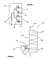
- the mixer-based electromagnetic radiation detector in general is of the type described in co-pending British patent application 0615140.1 , filed on 29 July 2006 , the description of which is herein incorporated by reference. It comprises a mixer channel "M" which is provided in use with a local oscillator signal via a branched waveguide 105. Detected radiation is delivered to the mixer channel "M" via a second waveguide 110.
- the mixer channel "M” is in practice provided by patterning on an elongate quartz substrate 120 which has a microstrip antenna at each end (not shown). Each antenna projects into a respective waveguide 105, 110.
- the mixer channel "M" and its waveguides 105, 110 are carried between pairs of substrates 100, 300.
- the substrates 100, 300 each have the path of the waveguides 105, 110 etched or machined into their surface and further etching or machining provides a chamber (not shown) for the mixer channel "M".
- this etching or machining is in register and provides the waveguides and chamber between the two substrates 100, 300. These each have a generally rectangular cross section.
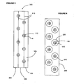
- three or more of the substrates 300, 100, 305 can be stacked, providing a set of waveguides 105, 110 along the interface 310 between each pair of substrates.
- the stack of substrates provides what can be referred to as a waveguide block 315, although it also offers the chambers for the mixer channels "M".
- the cross section of the waveguides 105, 110 is such that the interface 310 appears in the longer sidewalls of each waveguide 105, 110, this generally being best practice.
- each waveguide 110 delivering received radiation to each mixer channel "M" opens to a common face 125 of the waveguide block 315.
- each waveguide 110 has a short conical section 115 opening out to meet the face 125.
- These conical sections 115 can be drilled and they provide the transition from the rectangular cross section of the waveguides 110 to the circular cross section of a feedhorn.
- opposing walls of the waveguides 105, 110 have a discontinuity running parallel to the waveguiding direction of the respective waveguide, created by the interface 310 between each pair of substrates. However, there is no discontinuity, either in the walls of the waveguides 105, 110 or at the transition from the rectangular cross section of the waveguides 110 to the circular cross section of the conical sections 115, which lies transverse to the waveguiding direction.
- Figure 2 shows a cross section through a feedhorn block 200. It also shows part of the substrate 100 shown in Figure 1 in an assembled position against the feedhorn block 200 and in particular the alignment of a waveguide 110 and a conical end section 115 of a feedhorn on the substrate with the main body of a feedhorn 205 in the feedhorn block 200.
- each feedhorn 205 is provided by drilling through a separate feedhorn block 200.
- the feedhorn block 200 is then mounted against the face 125 of the waveguide block 315 so that each conical end section 115 of a feedhorn connects to the rest of a feedhorn 205.
- this leaves a discontinuity in the wall of each feedhorn 205 not far from its end section 115, which discontinuity is transverse to the longitudinal axis of the feedhorn 205, it has been found that this is much less significant than a transverse discontinuity lying right at the transition from waveguide 110 to feedhorn 205.
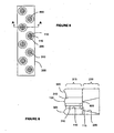
- a conical end section 115 for a feedhorn 205 can be seen in enlarged view.
- the opening of a waveguide 110 at the face 125 of the waveguide block 315 is simply drilled to create an aligned conical opening.
- the wall of the conical opening has two opposing discontinuities created by the interface 310 between two substrates (100, 305; 100, 300) of the waveguide block 315. However, these extend in an axial direction relative to the conical section 115.
- the distance from the face 125 of the waveguide block 315 to the transition from waveguide 110 to feedhorn 205 will be set by the feedhorn performance characteristics required.
- the length and feedhorn/waveguide spacing can be adjusted arbitrarily depending on the required array configuration and optics requirements.
- Feedhorn technology is established and the overall dimensions chosen for the waveguides 110 and feedhorns 205 will generally be chosen in accordance with the expected application.
- An example of a book on the subject is " Antennas for All Applications", third edition,.J.D.Kraus, R.J.Marhefka, published by McGraw-Hill in 2002 .
- a feedhorn will generally discriminate in terms of the wavelength band of radiation it receives or transmits and its design therefore has to be tailored accordingly.
- An example for use with THz radiation might have a cross section which is 1.33 mm in diameter at its narrow end and 7.001 mm in diameter at its wide end, its walls being at an angle of 18.9° to each other.
- the important dimensions of a feedhorn are generally the dimensions of the inner or "internal" surface of the feedhorn that will provide a boundary to travel of radiation in use of the feedhorn and thus references to dimensions, shapes, cross sections and sizes herein in relation to a feedhorn are generally references to this internal surface.
- the interface at the front face 125 of the waveguide block 315 can be taken advantage of in producing more complex horn designs such as the known 'Potter' or 'mode matched' horn (as would be understood by somebody skilled in the art).
- a shoulder 800 appears at the front face 125 of the waveguide block 315.
- a step discontinuity 800 of this type, between the main feedhorn taper and the waveguide/taper transition block 315 as shown in Figures 8 and 9 allows further second order adjustment of the feedhorn properties to optimise the symmetrical nature of its radiation properties.
- the shape of the feedhorn 205 or feedhorns 205 may have other characteristics, such as a flare or additional discontinuities. It is not essential that a feedhorn should have a conical internal profile.
- an example that is suitable for both the waveguide block 315 and the feedhorn block 200 is brass.
- suitable materials are other metals, such as gold, an alloy, a metal coated plastic or metal coated semiconductor.
- a method of making and assembling a waveguide/feedhorn assembly 315, 200 is as follows.
- a waveguide block 315 is made for example in the way described in co-pending British patent application 0615140.1, filed on 29 July 2006 .
- this block 315 may be based on four or more substrates with interfaces 310 therebetween.
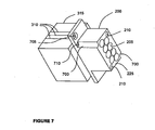
- a generally cuboid block of material such as brass is machined to give a pair of mounting flanges 215 on either side of a flat face 220.
- the body of the block extends away from that face 220 to a parallel face 225.
- Diagonally opposed corners 700 of the body of the block are machined away to give access to dowel holes 710.
- the other two corners of the body of the block have receiving sockets 210 for screws.
- the flanges 215 are each provided with a mounting hole 705.
- conical holes are drilled through the body of the feedhorn block 200. These are slightly less in diameter than the intended final size of the feedhorns 205.
- the feedhorn block 200 is then mounted in relation to the waveguide block 315 by using the holes 705 in the flanges 215 to mount the two blocks together in a frame or housing (not shown).
- Dowels in the dowel holes 710 provide accurate registration of the conical holes in the feedhorn block 315 with the waveguide openings of the waveguide block 315. It is only at this stage that the conical end sections 115 of the feedhorns 205 are produced in the waveguide openings.
- This technique achieves an array of feedhorns 205 with low losses in spite of the interface between the waveguide block 315 and the feedhorn block 200.
- Receiving sockets 210 for screws are mentioned above. These support further assembly of the waveguide and feedhorn blocks 315, 200 into finished equipment such as a camera.
- Machining and assembly of the waveguide and feedhorn blocks 315, 200 can be done using known techniques such as laser micromachining and/or optically controlled positioning and can generally be achieved to meet a tolerance of not more than 5 microns.
- Typical return losses between waveguide 110 and feedhorn 205 of better than - 27dB have been achieved in embodiments of the invention.
- the waveguides are produced as described above, based on a sandwich construction of layers brought together into register. Any other suitable techniques could be used.
- the use of preformed feedhorn apertures in a feedhorn block for alignment in drilling end portions of the feedhorns into waveguides for transmitting radiation therebetween in use of an assembly could potentially be useful however the waveguides are fabricated, as is the concept of creating "countersunk” end portions of the feedhorns into waveguide openings to avoid having a material interface right at the junction of the waveguide and feedhorn.
Landscapes
- Engineering & Computer Science (AREA)
- Electromagnetism (AREA)
- Power Engineering (AREA)
- Manufacturing & Machinery (AREA)
- Physics & Mathematics (AREA)
- Waveguide Aerials (AREA)
- Variable-Direction Aerials And Aerial Arrays (AREA)
- Transforming Light Signals Into Electric Signals (AREA)
- Measurement Of Radiation (AREA)
- Superheterodyne Receivers (AREA)
- Analysing Materials By The Use Of Radiation (AREA)
- Investigating Or Analysing Materials By Optical Means (AREA)
- Support Of Aerials (AREA)
Claims (15)
- Wellenleiter/Speisehorn-Baugruppe zur Verwendung in einem Detektor für elektromagnetische Strahlung, wobei die Baugruppe umfasst:einen Wellenleiterblock (315), der zumindest einen Teil eines Wellenleiters (110) und zumindest einen Endabschnitt (115) eines Speisehorns (205) aufweist,
wobei der Endabschnitt (115) des Speisehorns (205) und der zumindest eine Teil des Wellenleiters (110) zwischen sich eine Verbindungsstelle zur Abgabe von Strahlung aufweisen, und
der Teil des Wellenleiters (110) eine wellenleitende Fläche aufweist, deren Querschnitt zumindest im Wesentlichen viereckig ist,
dadurch gekennzeichnet, dass:der Endabschnitt (115) des Speisehorns (205) einen Innenquerschnitt quer zur Speiserichtung des Speisehorns aufweist, der zumindest im Wesentlichen gerundet ist, undder Endabschnitt (115) von einer Fläche (125) des Wellenleiterblocks (315) her eingesetzt ist, und die Verbindungsstelle zwischen dem Endabschnitt (115) und dem zumindest einen Teil des Wellenleiters (110) eine durchgehende Fläche in der wellenleitenden Richtung des Wellenleiters (110) aufweist. - Wellenleiter/Speisehorn-Baugruppe nach Anspruch 1, wobei die Baugruppe darüber hinaus umfasst:einen Speisehornblock (200), der zumindest einen Teil eines Speisehorns (205) in sich aufweist,
wobei der Speisehornblock (200) mit dem Wellenleiterblock (315) derart zusammengebaut ist, dass der Teil des Speisehorns (205) in dem Speisehornblock (200) mit dem Teil des Wellenleiters (110) in dem Wellenleiterblock (315) in Verbindung steht, um Strahlung zwischen diesen durch den Endabschnitt (115) des Speisehorns (205) abzugeben. - Wellenleiter/Speisehorn-Baugruppe nach Anspruch 2, wobei der Endabschnitt (115) des Speisehorns (205) in Bezug auf den Teil des Speisehorns (205) so bemessen ist, dass eine Stufe (800) in der Innenfläche des Speisehorns (205) entsteht.
- Wellenleiter/Speisehorn-Baugruppe nach einem der vorhergehenden Ansprüche, wobei der Innenquerschnitt des Endabschnitts (115) des Speisehorns (205) kreisförmig ist.
- Wellenleiter/Speisehorn-Baugruppe nach einem der vorhergehenden Ansprüche, wobei der Wellenleiterblock (315) mindestens zwei Schichten (100, 300) umfasst, wobei der Teil des Wellenleiters (110) an einer Grenzfläche (310) zwischen den beiden Schichten (100, 300) bereitgestellt ist.
- Wellenleiter/Speisehorn-Baugruppe nach Anspruch 5, wobei der Teil des Wellenleiters (110) durch eine Ausnehmung in jeder der beiden Schichten (100, 300) bereitgestellt ist, wobei die Ausnehmungen in der Baugruppe deckungsgleich sind.
- Wellenleiter/Speisehorn-Baugruppe nach Anspruch 6, wobei der Teil des Wellenleiters (110) eine wellenleitende Fläche hat, deren Querschnitt zumindest im Wesentlichen rechteckig ist, und die Grenzfläche (310) zwischen den beiden Schichten (100, 300) in den Längsseiten des Querschnitts vorhanden ist.
- Wellenleiter/Speisehorn-Baugruppe nach einem der vorhergehenden Ansprüche zur Verwendung in einem Detektor für Terahertzstrahlung.
- Wellenleiter/Speisehorn-Baugruppe nach einem der vorhergehenden Ansprüche, wobei die Baugruppe eine Gruppe von mehr als einem Wellenleiter(110) und mehr als einem Speisehorn (205) umfasst.
- Wellenleiter/Speisehorn-Baugruppe nach einem der Ansprüche 2 bis 9, wobei der Speisehornblock (200) eine Anordnung von Speisehornstrahleröffnungen umfasst, und der Wellenleiterblock eine dazu passende Anordnung von Wellenleitern umfasst, wobei jede Speisehornstrahleröffnung mit einem jeweiligen Wellenleiter in Verbindung steht.
- Verfahren zur Herstellung einer Wellenleiter/Speisehorn-Baugruppe zur Verwendung in einem Detektor für elektromagnetische Strahlung, das die folgenden Schritte umfasst:Herstellen eines Wellenleiterblocks (315), der zumindest einen Wellenleiter (110) bereitstellt, der eine zumindest im Wesentlichen viereckige Öffnung in einer Fläche (125) des Wellenleiterblocks (315) aufweist;Herstellen eines Speisehornblocks (200), der mindestens eine Speisehornstrahleröffnung durch den Speisehornblock (200) aufweist;Zusammenbauen des Speisehornblocks (200) mit dem Wellenleiterblock (315) so, dass die Speisehornstrahleröffnung deckungsgleich mit der Wellenleiteröffnung ist; undHerstellen eines Endabschnitts (115) des Speisehorns (205) in der Wellenleiteröffnung des Wellenleiterblocks (315) durch Bohren eines zumindest im Wesentlichen gerundeten Ausschnitts (115).
- Verfahren nach Anspruch 11, wobei der Schritt des Herstellens eines Endabschnitts (115) des Speisehorns (205) umfasst, den Endabschnitt (115) in Übereinstimmung mit der Speisehornstrahleröffnung auszurichten.
- Verfahren nach einem der Ansprüche 11 oder 12, wobei der Schritt des Herstellens eines Endabschnitts (115) des Speisehorns (205) darüber hinaus umfasst, die Speisehornstrahleröffnung endzubearbeiten, um eine Innenfläche des Speisehorns (205) zum Zuführen von Strahlung im Gebrauch der Baugruppe bereitzustellen.
- Verfahren nach einem der Ansprüche 11 bis 13, wobei der Schritt des Herstellens eines Wellenleiterblocks (315) die Schritte umfasst, mindestens eine langgestreckte Ausnehmung in einer Fläche einer ersten Materialschicht (100) zu schaffen und eine Fläche einer zweiten Materialschicht (300) angrenzend an die Fläche der ersten Schicht anzufügen, um den Wellenleiter (110) in dem Block (315) bereitzustellen.
- Verfahren nach Anspruch 14, darüber hinaus den Schritt umfassend, mindestens eine langgestreckte Ausnehmung mit einer komplementären Form in der Fläche der zweiten Schicht (300) zu schaffen, wobei die Ausnehmungen durch den Schritt des Anfügens der Fläche der zweiten Schicht (300) in Deckungsgleichheit gebracht werden, so dass der Wellenleiter (110) zum Teil durch jede der Ausnehmungen bereitgestellt wird.
Applications Claiming Priority (3)
| Application Number | Priority Date | Filing Date | Title |
|---|---|---|---|
| US79473206P | 2006-04-25 | 2006-04-25 | |
| GB0615140A GB0615140D0 (en) | 2006-07-29 | 2006-07-29 | Radiation detector |
| PCT/GB2007/001525 WO2007122413A1 (en) | 2006-04-25 | 2007-04-25 | Feedhorn assembly and method of fabrication thereof |
Publications (2)
| Publication Number | Publication Date |
|---|---|
| EP2016644A1 EP2016644A1 (de) | 2009-01-21 |
| EP2016644B1 true EP2016644B1 (de) | 2011-08-17 |
Family
ID=38222273
Family Applications (2)
| Application Number | Title | Priority Date | Filing Date |
|---|---|---|---|
| EP20070732560 Active EP2016671B1 (de) | 2006-04-25 | 2007-04-25 | Strahlungsdetektor |
| EP20070732562 Active EP2016644B1 (de) | 2006-04-25 | 2007-04-25 | Feedhorn-baugruppe und herstellungsverfahren dafür |
Family Applications Before (1)
| Application Number | Title | Priority Date | Filing Date |
|---|---|---|---|
| EP20070732560 Active EP2016671B1 (de) | 2006-04-25 | 2007-04-25 | Strahlungsdetektor |
Country Status (6)
| Country | Link |
|---|---|
| US (1) | US8134515B2 (de) |
| EP (2) | EP2016671B1 (de) |
| JP (2) | JP5407011B2 (de) |
| AT (1) | ATE521106T1 (de) |
| IL (1) | IL194930A (de) |
| WO (2) | WO2007122413A1 (de) |
Families Citing this family (6)
| Publication number | Priority date | Publication date | Assignee | Title |
|---|---|---|---|---|
| US7873329B2 (en) | 2006-04-25 | 2011-01-18 | ThruVision Systems Limited | Transceiver having mixer/filter within receiving/transmitting cavity |
| JP5334242B2 (ja) * | 2008-09-05 | 2013-11-06 | 大学共同利用機関法人自然科学研究機構 | 受信イメージングアンテナアレイ |
| CN106788267B (zh) * | 2016-11-29 | 2019-09-13 | 四川众为创通科技有限公司 | 基于废弃单片的异构集成太赫兹混频器及其实现方法 |
| JP6789086B2 (ja) * | 2016-12-05 | 2020-11-25 | 日本無線株式会社 | 基板側面ホーンアンテナ |
| CA3156478A1 (en) * | 2019-10-17 | 2021-04-22 | Thruvision Limited | HIGH FREQUENCY HETERODYNE MIXER |
| IL292203B2 (en) | 2019-10-17 | 2025-09-01 | Thruvision Ltd | Method and device for detecting high frequencies |
Family Cites Families (25)
| Publication number | Priority date | Publication date | Assignee | Title |
|---|---|---|---|---|
| US650448A (en) | 1899-07-17 | 1900-05-29 | Charles S Beebe | Chair. |
| GB603193A (en) | 1944-11-11 | 1948-06-10 | Olof Ollert | Improvements in or relating to kitchen ranges |
| BE527584A (de) | 1952-05-08 | |||
| US4090203A (en) * | 1975-09-29 | 1978-05-16 | Trw Inc. | Low sidelobe antenna system employing plural spaced feeds with amplitude control |
| US4048568A (en) | 1976-08-30 | 1977-09-13 | The United States Of America As Represented By The Secretary Of The Army | Wide operating frequency range superheterodyne fm noise analyzer |
| DE2939562C2 (de) * | 1979-09-29 | 1982-09-09 | Licentia Patent-Verwaltungs-Gmbh, 6000 Frankfurt | Hornstrahler als Erreger für eine Reflektorantenne mit einem Hybridmoden-Anregungsteil |
| US4406020A (en) | 1981-07-29 | 1983-09-20 | The United States Of America Represented By The Secretary Of The Navy | Millimeter wave printed circuit mixer |
| JPS6144904U (ja) * | 1984-08-27 | 1986-03-25 | 三菱電機株式会社 | 導波管回路 |
| FR2582865B1 (fr) * | 1985-06-04 | 1987-07-31 | Labo Electronique Physique | Modules unitaires d'antenne hyperfrequences et antenne hyperfrequences comprenant de tels modules |
| US4760404A (en) * | 1986-09-30 | 1988-07-26 | The Boeing Company | Device and method for separating short-wavelength and long-wavelength signals |
| US5023866A (en) | 1987-02-27 | 1991-06-11 | Motorola, Inc. | Duplexer filter having harmonic rejection to control flyback |
| US5062149A (en) | 1987-10-23 | 1991-10-29 | General Dynamics Corporation | Millimeter wave device and method of making |
| JPH0292001A (ja) * | 1988-09-28 | 1990-03-30 | Murata Mfg Co Ltd | 誘電体同軸フィルタ |
| JPH0918363A (ja) | 1995-07-04 | 1997-01-17 | Matsushita Electric Ind Co Ltd | ダブルスーパヘテロダインチューナ |
| GB9603196D0 (en) * | 1996-02-15 | 1996-04-17 | Council Cent Lab Res Councils | Waveguide structures and a method of fabrication thereof |
| JP2000165113A (ja) * | 1998-11-24 | 2000-06-16 | Murata Mfg Co Ltd | 高周波回路装置および無線装置 |
| JP2001094334A (ja) * | 1999-09-22 | 2001-04-06 | Mitsubishi Electric Corp | アンテナ素子、これを用いたアレイアンテナ及びアンテナ素子の製造方法 |
| US7095379B2 (en) * | 2001-06-09 | 2006-08-22 | Atk Alliant Techsystems, Inc. | Radio frequency component and method of making same |
| US7164902B2 (en) | 2001-11-01 | 2007-01-16 | Sharp Kabushiki Kaisha | Filter-integrated even-harmonic mixer and hi-frequency radio communication device using the same |
| EP1326107A3 (de) * | 2002-01-04 | 2004-03-10 | JDS Uniphase Corporation | Athermischer optischer Koppler |
| TWI248723B (en) | 2002-02-22 | 2006-02-01 | Accton Technology Corp | Impedance match circuit for rejecting an image signal via a microstrip structure |
| EP1520321A1 (de) * | 2002-06-27 | 2005-04-06 | Memgen Corporation | Miniaturisierte rf- und mikrowellenbauelemente und zugehöriges herstellungsverfahren |
| GB0224912D0 (en) | 2002-10-25 | 2002-12-04 | Council Cent Lab Res Councils | Sub-millimetre wavelength camera |
| JP3851900B2 (ja) * | 2002-11-25 | 2006-11-29 | シャープ株式会社 | 平面フィルタ、半導体装置、および無線装置 |
| WO2005038975A1 (ja) * | 2003-10-15 | 2005-04-28 | Intelligent Cosmos Research Institute | Nrdガイドトランシーバ、これを用いたダウンロードシステムおよびこれに用いられるダウンロード用メモリ |
-
2007
- 2007-04-25 EP EP20070732560 patent/EP2016671B1/de active Active
- 2007-04-25 EP EP20070732562 patent/EP2016644B1/de active Active
- 2007-04-25 WO PCT/GB2007/001525 patent/WO2007122413A1/en not_active Ceased
- 2007-04-25 WO PCT/GB2007/001523 patent/WO2007125326A1/en not_active Ceased
- 2007-04-25 JP JP2009507159A patent/JP5407011B2/ja active Active
- 2007-04-25 AT AT07732562T patent/ATE521106T1/de not_active IP Right Cessation
- 2007-04-25 JP JP2009507160A patent/JP2009534976A/ja active Pending
- 2007-04-25 US US12/298,360 patent/US8134515B2/en active Active
-
2008
- 2008-10-26 IL IL194930A patent/IL194930A/en active IP Right Grant
Also Published As
| Publication number | Publication date |
|---|---|
| US8134515B2 (en) | 2012-03-13 |
| WO2007125326A1 (en) | 2007-11-08 |
| EP2016671B1 (de) | 2014-07-02 |
| JP2009534975A (ja) | 2009-09-24 |
| US20090115676A1 (en) | 2009-05-07 |
| WO2007122413A1 (en) | 2007-11-01 |
| JP2009534976A (ja) | 2009-09-24 |
| EP2016644A1 (de) | 2009-01-21 |
| ATE521106T1 (de) | 2011-09-15 |
| JP5407011B2 (ja) | 2014-02-05 |
| EP2016671A1 (de) | 2009-01-21 |
| IL194930A0 (en) | 2009-08-03 |
| IL194930A (en) | 2012-12-31 |
Similar Documents
| Publication | Publication Date | Title |
|---|---|---|
| EP2016644B1 (de) | Feedhorn-baugruppe und herstellungsverfahren dafür | |
| US9960495B1 (en) | Integrated single-piece antenna feed and circular polarizer | |
| US10340574B2 (en) | Spatial combining device and antenna | |
| US9287614B2 (en) | Micromachined millimeter-wave frequency scanning array | |
| CN101141023A (zh) | 微机电层叠式毫米波天线 | |
| US8217852B2 (en) | Compact loaded-waveguide element for dual-band phased arrays | |
| EP1304762A3 (de) | Übergangsstruktur zwischen einer Übertragungsleitung und einem Hohlleiter | |
| US10854984B2 (en) | Air-filled quad-ridge radiator for AESA applications | |
| CN112313836A (zh) | 毫米波天线、天线组件、毫米波雷达系统和可移动平台 | |
| JP4188456B2 (ja) | フォーカルフィード反射器アンテナのための小型モノパルスソース | |
| US6642905B2 (en) | Thermal-locate 5W(V) and 5W(H) SSPA's on back of reflector(s) | |
| US8686813B2 (en) | Monolithically integrated active electronic circuit and waveguide structure for terahertz frequencies | |
| US20070210882A1 (en) | Ortho-Mode Transducer With Opposing Branch Waveguides | |
| CN101479890A (zh) | 喇叭天线组件及其制造方法 | |
| US9791321B2 (en) | 340 GHz multipixel transceiver | |
| EP3391465B1 (de) | Ultrabreitband-hf-/optische apertur | |
| US4654613A (en) | Radar rotary joint | |
| US10498446B2 (en) | Electronic system including waveguide with passive optical elements and related methods | |
| JP2022185566A (ja) | 集積ダイプレクサを備えた小型で薄型の開口アンテナ | |
| EP1875549A2 (de) | Hochfrequenz-empfänger für elektromagnetische wellen und breitband-wellenleitermischer | |
| Li et al. | Research on a New Compound Antenna for Millimeter Wave/infrared Seeker | |
| US20190386395A1 (en) | Antenna device and radio device | |
| RU2324269C2 (ru) | Конструкция выходного узла передающего канала модуля фазированной антенной решетки | |
| JPH1075125A (ja) | バランス形ミキサ | |
| Sickinger | Design and Characterization of 76-81 GHz LTCC Antenna Structures for Automotive Miniature Radar Front Ends |
Legal Events
| Date | Code | Title | Description |
|---|---|---|---|
| PUAI | Public reference made under article 153(3) epc to a published international application that has entered the european phase |
Free format text: ORIGINAL CODE: 0009012 |
|
| 17P | Request for examination filed |
Effective date: 20081121 |
|
| AK | Designated contracting states |
Kind code of ref document: A1 Designated state(s): AT BE BG CH CY CZ DE DK EE ES FI FR GB GR HU IE IS IT LI LT LU LV MC MT NL PL PT RO SE SI SK TR |
|
| AX | Request for extension of the european patent |
Extension state: AL BA HR MK RS |
|
| 17Q | First examination report despatched |
Effective date: 20090408 |
|
| GRAP | Despatch of communication of intention to grant a patent |
Free format text: ORIGINAL CODE: EPIDOSNIGR1 |
|
| DAX | Request for extension of the european patent (deleted) | ||
| GRAS | Grant fee paid |
Free format text: ORIGINAL CODE: EPIDOSNIGR3 |
|
| GRAA | (expected) grant |
Free format text: ORIGINAL CODE: 0009210 |
|
| RAP1 | Party data changed (applicant data changed or rights of an application transferred) |
Owner name: THRUVISION SYSTEMS LIMITED |
|
| AK | Designated contracting states |
Kind code of ref document: B1 Designated state(s): AT BE BG CH CY CZ DE DK EE ES FI FR GB GR HU IE IS IT LI LT LU LV MC MT NL PL PT RO SE SI SK TR |
|
| REG | Reference to a national code |
Ref country code: GB Ref legal event code: FG4D |
|
| REG | Reference to a national code |
Ref country code: CH Ref legal event code: EP |
|
| REG | Reference to a national code |
Ref country code: IE Ref legal event code: FG4D |
|
| REG | Reference to a national code |
Ref country code: DE Ref legal event code: R096 Ref document number: 602007016579 Country of ref document: DE Effective date: 20111020 |
|
| REG | Reference to a national code |
Ref country code: NL Ref legal event code: VDEP Effective date: 20110817 |
|
| LTIE | Lt: invalidation of european patent or patent extension |
Effective date: 20110817 |
|
| PG25 | Lapsed in a contracting state [announced via postgrant information from national office to epo] |
Ref country code: SE Free format text: LAPSE BECAUSE OF FAILURE TO SUBMIT A TRANSLATION OF THE DESCRIPTION OR TO PAY THE FEE WITHIN THE PRESCRIBED TIME-LIMIT Effective date: 20110817 Ref country code: LT Free format text: LAPSE BECAUSE OF FAILURE TO SUBMIT A TRANSLATION OF THE DESCRIPTION OR TO PAY THE FEE WITHIN THE PRESCRIBED TIME-LIMIT Effective date: 20110817 Ref country code: IS Free format text: LAPSE BECAUSE OF FAILURE TO SUBMIT A TRANSLATION OF THE DESCRIPTION OR TO PAY THE FEE WITHIN THE PRESCRIBED TIME-LIMIT Effective date: 20111217 Ref country code: NL Free format text: LAPSE BECAUSE OF FAILURE TO SUBMIT A TRANSLATION OF THE DESCRIPTION OR TO PAY THE FEE WITHIN THE PRESCRIBED TIME-LIMIT Effective date: 20110817 Ref country code: PT Free format text: LAPSE BECAUSE OF FAILURE TO SUBMIT A TRANSLATION OF THE DESCRIPTION OR TO PAY THE FEE WITHIN THE PRESCRIBED TIME-LIMIT Effective date: 20111219 Ref country code: FI Free format text: LAPSE BECAUSE OF FAILURE TO SUBMIT A TRANSLATION OF THE DESCRIPTION OR TO PAY THE FEE WITHIN THE PRESCRIBED TIME-LIMIT Effective date: 20110817 |
|
| REG | Reference to a national code |
Ref country code: AT Ref legal event code: MK05 Ref document number: 521106 Country of ref document: AT Kind code of ref document: T Effective date: 20110817 |
|
| PG25 | Lapsed in a contracting state [announced via postgrant information from national office to epo] |
Ref country code: LV Free format text: LAPSE BECAUSE OF FAILURE TO SUBMIT A TRANSLATION OF THE DESCRIPTION OR TO PAY THE FEE WITHIN THE PRESCRIBED TIME-LIMIT Effective date: 20110817 Ref country code: CY Free format text: LAPSE BECAUSE OF FAILURE TO SUBMIT A TRANSLATION OF THE DESCRIPTION OR TO PAY THE FEE WITHIN THE PRESCRIBED TIME-LIMIT Effective date: 20110817 Ref country code: GR Free format text: LAPSE BECAUSE OF FAILURE TO SUBMIT A TRANSLATION OF THE DESCRIPTION OR TO PAY THE FEE WITHIN THE PRESCRIBED TIME-LIMIT Effective date: 20111118 Ref country code: PL Free format text: LAPSE BECAUSE OF FAILURE TO SUBMIT A TRANSLATION OF THE DESCRIPTION OR TO PAY THE FEE WITHIN THE PRESCRIBED TIME-LIMIT Effective date: 20110817 Ref country code: AT Free format text: LAPSE BECAUSE OF FAILURE TO SUBMIT A TRANSLATION OF THE DESCRIPTION OR TO PAY THE FEE WITHIN THE PRESCRIBED TIME-LIMIT Effective date: 20110817 Ref country code: SI Free format text: LAPSE BECAUSE OF FAILURE TO SUBMIT A TRANSLATION OF THE DESCRIPTION OR TO PAY THE FEE WITHIN THE PRESCRIBED TIME-LIMIT Effective date: 20110817 |
|
| PG25 | Lapsed in a contracting state [announced via postgrant information from national office to epo] |
Ref country code: BE Free format text: LAPSE BECAUSE OF FAILURE TO SUBMIT A TRANSLATION OF THE DESCRIPTION OR TO PAY THE FEE WITHIN THE PRESCRIBED TIME-LIMIT Effective date: 20110817 |
|
| PG25 | Lapsed in a contracting state [announced via postgrant information from national office to epo] |
Ref country code: SK Free format text: LAPSE BECAUSE OF FAILURE TO SUBMIT A TRANSLATION OF THE DESCRIPTION OR TO PAY THE FEE WITHIN THE PRESCRIBED TIME-LIMIT Effective date: 20110817 Ref country code: CZ Free format text: LAPSE BECAUSE OF FAILURE TO SUBMIT A TRANSLATION OF THE DESCRIPTION OR TO PAY THE FEE WITHIN THE PRESCRIBED TIME-LIMIT Effective date: 20110817 |
|
| PG25 | Lapsed in a contracting state [announced via postgrant information from national office to epo] |
Ref country code: IT Free format text: LAPSE BECAUSE OF FAILURE TO SUBMIT A TRANSLATION OF THE DESCRIPTION OR TO PAY THE FEE WITHIN THE PRESCRIBED TIME-LIMIT Effective date: 20110817 Ref country code: EE Free format text: LAPSE BECAUSE OF FAILURE TO SUBMIT A TRANSLATION OF THE DESCRIPTION OR TO PAY THE FEE WITHIN THE PRESCRIBED TIME-LIMIT Effective date: 20110817 Ref country code: RO Free format text: LAPSE BECAUSE OF FAILURE TO SUBMIT A TRANSLATION OF THE DESCRIPTION OR TO PAY THE FEE WITHIN THE PRESCRIBED TIME-LIMIT Effective date: 20110817 |
|
| PLBE | No opposition filed within time limit |
Free format text: ORIGINAL CODE: 0009261 |
|
| STAA | Information on the status of an ep patent application or granted ep patent |
Free format text: STATUS: NO OPPOSITION FILED WITHIN TIME LIMIT |
|
| PG25 | Lapsed in a contracting state [announced via postgrant information from national office to epo] |
Ref country code: DK Free format text: LAPSE BECAUSE OF FAILURE TO SUBMIT A TRANSLATION OF THE DESCRIPTION OR TO PAY THE FEE WITHIN THE PRESCRIBED TIME-LIMIT Effective date: 20110817 |
|
| 26N | No opposition filed |
Effective date: 20120521 |
|
| REG | Reference to a national code |
Ref country code: DE Ref legal event code: R097 Ref document number: 602007016579 Country of ref document: DE Effective date: 20120521 |
|
| PG25 | Lapsed in a contracting state [announced via postgrant information from national office to epo] |
Ref country code: MC Free format text: LAPSE BECAUSE OF NON-PAYMENT OF DUE FEES Effective date: 20120430 |
|
| REG | Reference to a national code |
Ref country code: CH Ref legal event code: PL |
|
| REG | Reference to a national code |
Ref country code: IE Ref legal event code: MM4A |
|
| PG25 | Lapsed in a contracting state [announced via postgrant information from national office to epo] |
Ref country code: IE Free format text: LAPSE BECAUSE OF NON-PAYMENT OF DUE FEES Effective date: 20120425 Ref country code: LI Free format text: LAPSE BECAUSE OF NON-PAYMENT OF DUE FEES Effective date: 20120430 Ref country code: CH Free format text: LAPSE BECAUSE OF NON-PAYMENT OF DUE FEES Effective date: 20120430 |
|
| PG25 | Lapsed in a contracting state [announced via postgrant information from national office to epo] |
Ref country code: ES Free format text: LAPSE BECAUSE OF FAILURE TO SUBMIT A TRANSLATION OF THE DESCRIPTION OR TO PAY THE FEE WITHIN THE PRESCRIBED TIME-LIMIT Effective date: 20111128 |
|
| REG | Reference to a national code |
Ref country code: GB Ref legal event code: 732E Free format text: REGISTERED BETWEEN 20130404 AND 20130410 |
|
| PG25 | Lapsed in a contracting state [announced via postgrant information from national office to epo] |
Ref country code: BG Free format text: LAPSE BECAUSE OF FAILURE TO SUBMIT A TRANSLATION OF THE DESCRIPTION OR TO PAY THE FEE WITHIN THE PRESCRIBED TIME-LIMIT Effective date: 20111117 |
|
| PG25 | Lapsed in a contracting state [announced via postgrant information from national office to epo] |
Ref country code: MT Free format text: LAPSE BECAUSE OF FAILURE TO SUBMIT A TRANSLATION OF THE DESCRIPTION OR TO PAY THE FEE WITHIN THE PRESCRIBED TIME-LIMIT Effective date: 20110817 |
|
| REG | Reference to a national code |
Ref country code: DE Ref legal event code: R082 Ref document number: 602007016579 Country of ref document: DE Representative=s name: BARZ, PETER, DIPL.-CHEM. DR.RER.NAT., DE |
|
| REG | Reference to a national code |
Ref country code: FR Ref legal event code: TP Owner name: DIGITAL BARRIERS SERVICES LIMITED, GB Effective date: 20140102 |
|
| REG | Reference to a national code |
Ref country code: DE Ref legal event code: R082 Ref document number: 602007016579 Country of ref document: DE Representative=s name: MEISSNER, BOLTE & PARTNER GBR, DE Effective date: 20140202 Ref country code: DE Ref legal event code: R081 Ref document number: 602007016579 Country of ref document: DE Owner name: DIGITAL BARRIERS SERVICES LTD., GB Free format text: FORMER OWNER: THRUVISION SYSTEMS LIMITED, ABINGDON, GB Effective date: 20131217 Ref country code: DE Ref legal event code: R082 Ref document number: 602007016579 Country of ref document: DE Representative=s name: MEISSNER BOLTE PATENTANWAELTE RECHTSANWAELTE P, DE Effective date: 20131217 Ref country code: DE Ref legal event code: R082 Ref document number: 602007016579 Country of ref document: DE Representative=s name: MEISSNER BOLTE PATENTANWAELTE RECHTSANWAELTE P, DE Effective date: 20140130 Ref country code: DE Ref legal event code: R081 Ref document number: 602007016579 Country of ref document: DE Owner name: DIGITAL BARRIERS SERVICES LTD., GB Free format text: FORMER OWNER: THRUVISION SYSTEMS LIMITED, ABINGDON, OXFORDSHIRE, GB Effective date: 20131217 Ref country code: DE Ref legal event code: R082 Ref document number: 602007016579 Country of ref document: DE Representative=s name: MEISSNER, BOLTE & PARTNER GBR, DE Effective date: 20131217 Ref country code: DE Ref legal event code: R082 Ref document number: 602007016579 Country of ref document: DE Representative=s name: MEISSNER, BOLTE & PARTNER GBR, DE Effective date: 20140130 |
|
| PG25 | Lapsed in a contracting state [announced via postgrant information from national office to epo] |
Ref country code: TR Free format text: LAPSE BECAUSE OF FAILURE TO SUBMIT A TRANSLATION OF THE DESCRIPTION OR TO PAY THE FEE WITHIN THE PRESCRIBED TIME-LIMIT Effective date: 20110817 |
|
| PG25 | Lapsed in a contracting state [announced via postgrant information from national office to epo] |
Ref country code: LU Free format text: LAPSE BECAUSE OF NON-PAYMENT OF DUE FEES Effective date: 20120425 |
|
| PG25 | Lapsed in a contracting state [announced via postgrant information from national office to epo] |
Ref country code: HU Free format text: LAPSE BECAUSE OF FAILURE TO SUBMIT A TRANSLATION OF THE DESCRIPTION OR TO PAY THE FEE WITHIN THE PRESCRIBED TIME-LIMIT Effective date: 20070425 |
|
| REG | Reference to a national code |
Ref country code: FR Ref legal event code: PLFP Year of fee payment: 10 |
|
| REG | Reference to a national code |
Ref country code: GB Ref legal event code: 732E Free format text: REGISTERED BETWEEN 20161215 AND 20161221 |
|
| REG | Reference to a national code |
Ref country code: FR Ref legal event code: PLFP Year of fee payment: 11 |
|
| REG | Reference to a national code |
Ref country code: FR Ref legal event code: PLFP Year of fee payment: 12 |
|
| REG | Reference to a national code |
Ref country code: GB Ref legal event code: 732E Free format text: REGISTERED BETWEEN 20180823 AND 20180829 |
|
| REG | Reference to a national code |
Ref country code: DE Ref legal event code: R082 Ref document number: 602007016579 Country of ref document: DE Representative=s name: MEISSNER BOLTE PATENTANWAELTE RECHTSANWAELTE P, DE Ref country code: DE Ref legal event code: R081 Ref document number: 602007016579 Country of ref document: DE Owner name: THRUVISION LIMITED, ABINGDON, GB Free format text: FORMER OWNER: DIGITAL BARRIERS SERVICES LTD., LONDON, GB |
|
| P01 | Opt-out of the competence of the unified patent court (upc) registered |
Effective date: 20230601 |
|
| PGFP | Annual fee paid to national office [announced via postgrant information from national office to epo] |
Ref country code: DE Payment date: 20250423 Year of fee payment: 19 |
|
| PGFP | Annual fee paid to national office [announced via postgrant information from national office to epo] |
Ref country code: GB Payment date: 20250417 Year of fee payment: 19 |
|
| PGFP | Annual fee paid to national office [announced via postgrant information from national office to epo] |
Ref country code: FR Payment date: 20250422 Year of fee payment: 19 |