EP2016576B1 - Anzeigevorrichtung - Google Patents
Anzeigevorrichtung Download PDFInfo
- Publication number
- EP2016576B1 EP2016576B1 EP07731389A EP07731389A EP2016576B1 EP 2016576 B1 EP2016576 B1 EP 2016576B1 EP 07731389 A EP07731389 A EP 07731389A EP 07731389 A EP07731389 A EP 07731389A EP 2016576 B1 EP2016576 B1 EP 2016576B1
- Authority
- EP
- European Patent Office
- Prior art keywords
- ground
- cover
- upper face
- openings
- channels
- Prior art date
- Legal status (The legal status is an assumption and is not a legal conclusion. Google has not performed a legal analysis and makes no representation as to the accuracy of the status listed.)
- Not-in-force
Links
Images


Classifications
-
- G—PHYSICS
- G09—EDUCATION; CRYPTOGRAPHY; DISPLAY; ADVERTISING; SEALS
- G09F—DISPLAYING; ADVERTISING; SIGNS; LABELS OR NAME-PLATES; SEALS
- G09F19/00—Advertising or display means not otherwise provided for
- G09F19/22—Advertising or display means on roads, walls or similar surfaces, e.g. illuminated
- G09F2019/223—Advertising or display means on roads, walls or similar surfaces, e.g. illuminated in pavement panels
Definitions
- the present invention relates to the design and manufacture of an information display device.
- the invention relates more specifically to the display on the ground.
- the device it offers is particularly suitable for use outdoors, although it can also be used inside buildings.
- the display device is positioned in the car parks, at the end of the white stripes which delimit the parking spaces. It then serves as information carrier, but it also ensures advantageously at the same time a better delimitation of places.
- the invention does not exclude the use of the device for display on any other surface, especially on vertical surfaces, for example on the wall, or on the ceiling.
- the device according to the invention is intended for the display of all types of information, and more particularly of descriptive information, such as the indication of a commercial sign or information for reserving parking spaces, or else advertising information.
- Documents FR 2,606,540 and US 5,848,830 there are known information display devices for embedding in the ground or to be placed on the ground which provide a waterproof case in which a placard carrying the information message is stuck between a transparent upper plate at ground level and the upper face of the waterproof case.
- the object of the invention is to overcome the drawbacks of existing ground information display systems by proposing a ground information display device which can be easily arranged on any surface, without any particular preparation of the latter, and more particularly outside, and which ensures at the same time a good readability of the information.
- the device according to the invention comprises a fixing structure on the ground, with a convex upper face, and a convergent convex-shaped removable top transparent cover, between which there is a support poster information.
- the structure is hollowed out on its upper face of channels allowing the flow of water to orifices for discharging water to the ground.
- the channels advantageously delimit, in the structure, studs on which the lid comes to rest in the closed position.
- These studs have respective heights such, and their upper faces have a shape such that they constitute as a whole a bearing surface for the lid which is curved.
- the curved shape of the device which is imposed on the poster arranged wedged between the structure and the cover, increases the legibility of the information printed on the poster.
- This shape also limits the inconvenience to the ground, both for vehicles and for pedestrians.
- the lid bearing on the upper face of the pads and in combination with the constituent material which is advantageously chosen to be both flexible and resistant, it results in a better strength of all: a on the other hand, the studs play the role of reinforcement for the lid that bears on them; on the other hand, there remain between the studs spaces allowing the lid to deform vertically, without breaking, when pressure is exerted on him. Thanks to this solidity and this flexibility of deformation, the device according to the invention advantageously resists, without breaking, the passage over him of vehicles of several tons.
- the cover is further advantageously made of a material resistant to impacts, so that it does not deteriorate under the effect of impacts, including gravel projected on him with force.
- the space between the pads, defined by the water discharge channels, can advantageously serve as a receptacle for accessories associated with the device, especially for an autonomous backlight system of the poster.
- the device according to the invention is advantageously constituted in such a way that water (rainwater or soil washing) which enters its interior is evacuated spontaneously, by the channels which lead it, in particular by a slight slope, to the orifices by which it is eliminated towards the ground. It does not stagnate thus, inside the device, no water can deteriorate the poster.
- the device according to the invention thus advantageously allows a display of high quality, very good readability. It can be fixed on all types of soil, by gluing or screwing, without requiring special preparation or development of the latter. It constitutes only a slight inconvenience for the circulation, thanks to its curved shape and its height, which is preferably chosen to be reduced, of the order of 20 mm at its maximum in its central part.
- the invention furthermore meets the following characteristics, implemented separately or in each of their technically operating combinations.
- the studs are recessed on the underside of the structure, so that on the one hand the latter is lighter and less expensive to manufacture, and on the other hand the device has a better flexibility of deformation under the effect of a vertical or lateral pressure exerted on him. It is so much stronger.
- the pads are connected in pairs by thin side rails. These sleepers are preferably also in contact against the lid in the closed position, so that they further strengthen the latter.
- the poster used is classic in itself. It is preferably plasticized, to make it more resistant to moisture, or formed in a thick cardboard for a short display, especially a few weeks. All types of messages, including the most complex, can be broadcast through it.
- the poster is coated on its upper face with an adhesive layer, so that it can be glued against the underside of the lid.
- the readability of the poster is in this still improved, since the infiltration of moisture between the poster and the lid is avoided.
- the cover is fixed on the structure by elastic engagement of tabs in cooperating orifices formed thereon.
- the tabs are preferably chosen sufficiently long to be able to be cleared from the corresponding orifices only under the effect of a strong lateral pressure exerted on either side of the lid, and in particular to be able to be released by a simple manual pressure .
- the device according to the invention thus advantageously offers a high degree of protection against theft of the poster by disconnecting the cover and the structure attached to the ground.
- the structure comprises on its upper face, at the outer edge of each of the orifices, a notch allowing the insertion of tongs for the disengagement of the tabs by pressure on opposite side faces of the lid, in a constriction. from the latter to each other.
- the cover can therefore be easily detached from the structure, by means of a suitable tool, when you want to replace the poster.
- the device according to the invention is advantageously associated with a specific tool, allowing the removal of the cover attached to the structure.
- This tool comprises, at the lower end of elongated control rods for maneuvering by a user in a standing position, clamps operable simultaneously by the same control operation. These clamps are arranged so as to be inserted simultaneously respectively into all the notches of the structure, so as to allow the disengagement of the tabs of the lid out of their respective cooperating orifices.
- the lid can therefore be detached from the structure very comfortably by a standing user, without having to bend or bend.
- the large length of the control rods of the clamps also makes it possible to reduce the effort required to print on the lid a lateral pressure that is strong enough to disengage the tabs from their respective orifices.
- the same tool can advantageously be used for the installation of a cover on a structure attached to the ground, always in a standing position.
- the structure has on its underside, covered by the lid in the closed position, through holes for fixing to the ground by screwing or gluing, evenly distributed over the entire surface of the canals.
- These orifices are advantageously the same as the water discharge orifices, those of the latter not being used for fixing to the ground ensuring the evacuation of the water having penetrated into the device.
- a strong and resistant fastening is advantageously obtained, in particular with regard to the lateral forces exerted on the device by the wheels of vehicles rolling over it, in that the adhesive applied between the underside of the structure and the soil penetrates through the orifices, and overflows inside the device forming, after its solidification, the equivalent of a fastening system by rivets particularly effective.
- the device according to the invention therefore has, when it is fixed by gluing, a significant resistance to tearing of the soil.
- the structure comprises, on the periphery of its lower face intended to be in contact with the ground, radial grooves improving its adhesion to the ground.
- the fact that the fixing to the ground is effected by through holes in the structure, arranged under the cover in closed position, advantageously provides protection against theft of the device attached to the ground.
- the device according to the invention therefore offers a high degree of security against theft.
- a further object of the invention is to ensure good security conditions for users of the device.
- the cover comprises on its upper face an anti-slip coating
- the structure comprises, at the opposite longitudinal ends of its upper face, anti-adhesion patterns, although the risks of slipping by pedestrians or two wheels on these areas of the device are avoided.
- the device preferably has an elongated and curved shape in the middle, which increases its ergonomics and facilitates its crossing, and all its outside corners are rounded, so that there is no risk of injury or puncture for users.
- the cover further comprises on its upper face an anti-scratch coating, improving the readability of the poster.
- the cover is preferably provided on its underside with loops receiving cooperating legs carried by the poster on its outer periphery. These loops are regularly distributed along the periphery of the lid. This advantageously allows a better holding of the poster against the surface of the lid. Mounting the poster against the lid is also easy. In addition, quite advantageously from an industrial point of view, the poster can be mounted in the cover at the factory, and the whole, securely fastened, be transported to the place where the structure is fixed to the ground , to replace a set "lid - obsolete poster" in place.
- the device according to the invention comprises a ground fixing structure 1 and a cover 2 cooperating with this structure.
- each of these elements are defined relative to the normal position of use of the device, the latter resting on the ground by the underside of the structure 1, and the cover 2, disposed on the upper face of the the latter forming an upper face of the device.
- the lid 2 is transparent. ,
- An information support poster which is not shown in the figures for the sake of clarity, is arranged between the structure 1 and the cover 2, with the face on which the information directed upwards is printed.
- This poster is classic in itself. It is preferably plasticized for long-term outdoor use, so as to withstand moisture conditions. It can also be a thick cardboard poster, in cases where the information message it broadcasts is intended to be displayed for a short period.
- the poster may have on its upper face, bearing the information, an adhesive layer for its bonding against the surface of the lid 2. This layer is in particular constituted by a double-sided adhesive, one side adheres to the poster and the other to the lid.
- Structure 1 is made of a material that is both light and strong, in particular aluminum.
- the cover 2 is itself made of a plastic material that is both flexible and resistant to shocks, in particular polycarbonate. It is preferably covered on its upper face, an anti-scratch and non-slip coating.
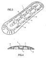
- Both the structure 1 and the cover 2 have a convex shape, as can be seen in the figure 4 which is a sectional view of the device along a plane transverse to it.
- the device has a generally elongated and curved shape in the middle, which facilitates its crossing. It has a substantially zero thickness at its longitudinal edges, and increasing to about 20 mm in its central portion. Its width and length may vary depending on the application. They may be for example respectively about 15 cm and about 50 to 60 cm.
- the structure 1 On its opposite longitudinal end zones 3, which are not covered by the cover 2, the structure 1 comprises anti-adhesion patterns 4, consisting of prominent radial bars, which reduce the risk of slipping in passing these areas.
- the structure 1 On its upper face, the structure 1 is hollowed with channels 5 which crisscross its surface. These channels 5 allow the flow of water that could have burst in the device, at the intersection of the structure 1 and the cover 2, to orifices 6 passing through the thickness of the structure 1, which ensure the evacuation of this water out of the device, towards the ground.
- the channels 5 delimit on the structure 1 prominent studs 7. They are arranged so as to evacuate the water efficiently wherever it has infiltrated.
- a channel 5 forms a peripheral ring in the bottom of the structure 1, and another, the central channel 8 is disposed along the longitudinal axis of the device.
- Four transverse channels connect these two channels, as shown in particular on the figure 3 .
- the water discharge orifices 6 are arranged at locations regularly distributed over the entire bottom of the structure, in the channels 5.
- Each of the studs 7 has an upper face inclined towards the longitudinal axis of the device, so as to form the convex upper face of the structure 1, as can be seen on the Figures 3 and 4 .
- the studs 7 arranged on either side of the central channel 8 are connected to each other by thin cross members 9, which make it possible to reinforce the strength of the structure 1, with one or two sleepers 9 for each pair of studs 7 connected to each other.
- the pads 7 are hollow, so that the structure 1 is lighter.
- the structure 1 can be fixed to the ground by gluing or screwing.
- the bonding is carried out by applying a layer of glue, conventional in itself for this kind of application, under the underside of the structure 1, at the level of the channels 5, and pressure of the underside of the device thus glued. against the receiving soil surface.
- the glue is preferably applied in at least one peripheral ring located under the peripheral channel 5. The glue then penetrates into some of the orifices 6 formed in the channels 5, and it overflows slightly on the upper face of the structure 1, before reaching solidify in this configuration, so that the bonding is made in a strong manner and resistant to tearing.
- Orifers 10 of slightly larger diameter are provided for fixing to the ground by screwing. These holes are preferably arranged along the longitudinal axis of the device, in the central channel 8, between the pairs of studs 7 and the crosspieces 9, so as to ensure screw fixing as solid as possible.
- the structure 1 comprises, on the periphery of its lower face, visible on the figure 2 , radial grooves 11 promoting its adhesion to the ground.
- the poster support information is stuck between the structure 1 and the cover 2, applied by its lower face on the upper face of the pads 7, and the cover 2 coming to press on its upper face.
- the lid 2 comprises, on its longitudinal edges, tabs 12, three in number regularly distributed along each edge in the embodiment shown here. These lugs 12 are intended to be inserted into cooperating orifices 13 formed on the structure 1. The attachment of the lid 2 to the structure 1 is effected in a simple and easy manner, by elastic engagement of the lugs 12 in the orifices 13.
- a notch 14 is provided on the upper face of the structure 1, at the outer edge of each orifice 13, as shown in FIG. figure 4 .
- These notches 14 make it possible to grip the cover 2 above each lug 13, by means of a clamp, and, by exerting a simultaneous pressure in tightening towards each other, above each of two lugs. vis-à-vis, disengage the tabs 12 of their respective receiving holes 13, so as to separate the lid 2, for example to replace the poster.
- the device is associated with a specific tool 15 for removing the cover 2 of the structure 1, which is shown on the figure 5 .
- This tool has two elongated rods 16, of sufficient length to come, when the lower end of the tool is placed on the device attached to the ground, at the height of the hand of a standing user.
- At the lower end of the rods 16 are three clamps 17, arranged parallel to each other with their gripping arms directed downwards, and articulated about the same axis 18 perpendicular to the rods 16.
- the clamps 17 are also connected, at their gripping arms, respectively by rods 19 parallel to the axis 18.
- the rods 16 are connected to the central clamp, so as to actuate its movement by spacing or tightening of the two rods 16 compared to each other. This movement is transmitted to the other two clamps 17 by the rods 19.
- the clamps 17 are spaced from each other and dimensioned so that their gripping ends 20 each fit, simultaneously, respectively into one of the notches 14 of the device, as shown in FIG. figure 5 , so as to allow the cover 2 to be gripped over the tabs 12 and the disengagement of the latter from the orifices 13.
- the device according to the invention can in particular be equipped with solar collectors, connected to accumulators which can be arranged in the channels 5, between the studs 7. These accumulators can feed a light stud system disposed inside the device, under the poster, so as to make the latter readable under backlight dark conditions, and / or system for broadcasting sound messages also arranged between the pads 7.
- the device may also include diodes, arranged in orifices provided for this purpose, particularly at its ends, so as to allow a more effective visual delineation of the parking spaces.
Landscapes
- Business, Economics & Management (AREA)
- Accounting & Taxation (AREA)
- Marketing (AREA)
- Physics & Mathematics (AREA)
- General Physics & Mathematics (AREA)
- Engineering & Computer Science (AREA)
- Theoretical Computer Science (AREA)
- Road Signs Or Road Markings (AREA)
- Devices For Indicating Variable Information By Combining Individual Elements (AREA)
- Indicating And Signalling Devices For Elevators (AREA)
- Diaphragms For Electromechanical Transducers (AREA)
- Measuring Pulse, Heart Rate, Blood Pressure Or Blood Flow (AREA)
- Vehicle Body Suspensions (AREA)
- Floor Finish (AREA)
- Illuminated Signs And Luminous Advertising (AREA)
Claims (10)
- Anzeigevorrichtung, dadurch gekenzeichnet dass sie ein Bodenbauteil (1) mit einer konvex gewölbten Oberseite zur Bodenbefestigung und einem durchsichtigen, abnehmbaren oberen Deckel mit zusammenwirkender konvex Wölbung umfässt, zwischen denen ein Informationsträger angeordnet werden kann, und dass das Bodenbauteil (1) auf seiner Oberseite mit Kanälen (5) durchgezogen ist, die den Abfluss vom Wasser durch Ausflussöffnungen (6) zum Boden hin erlauben.
- Vorrichtung nach Anspruch 1, dadurch gekennzeichnet, dass die Kanäle (5) in dem Bodenbauteil (1) Blöcke (7) begrenzen, die in ihrer Gesamtheit als eine gewölbt stützende Oberfläche für den Deckel (2) in Schließposition wirken.
- Vorrichtung nach Anspruch 2, dadurch gekennzeichnet, dass die Blöcke (7) auf der Unterseite des Bodenbauteils (1) ausgehöhlt sind.
- Vorrichtung nach Anspruch 2 oder 3, dadurch gekennzeichnet, dass die Blöcke (7) paarweise durch schmale seitliche Stege (9) verbunden sind.
- Vorrichtung nach einem der Ansprüche 1 bis 4, dadurch gekennzeichnet, dass der Deckel (2) sich auf dem Bauteil (1) durch elastische Befestigung über Vorsprünge (12) in zusammenwirkenden Öffnungen (13) hält, die in dem Bauteil (1) vorgesehen sind, und dadurch, dass das Bauteil (1) auf seiner Oberseite am Außenrand jeder der Öffnungen (13) jeweils eine Einkerbung (14) besitzt, wobei die Einkerbung (14) die Einführung von Zangenbacken für das Trennen der Vorsprünge durch Druck auf die gegenüberliegenden Seitenflächen des Deckels (2) ermöglicht.
- Vorrichtung nach einem der Ansprüche 1 bis 5, dadurch gekennzeichnet, dass das Bodenbauteil (1) auf seiner Unterseite traversierende Öffnungen (6,10) für die Bodenbefestigung durch Verschraubung oder Verklebung, regelmäßig verteilt auf der gesamten Oberfläche der Kanäle (5), aufweist.
- Vorrichtung nach einem der Ansprüche 1 bis 6, dadurch gekennzeichnet, dass das Bodenbauteil (1) auf der Peripherie seiner Unterseite, die dazu bestimmt ist, den Boden zu kontaktieren, radial verlaufende Rillen (11) aufweist, die die Haftung der Vorrichtung am Boden verbessern.
- Vorrichtung nach einem der Ansprüche 1 bis 7, dadurch gekennzeichnet, dass der Deckel (2) auf seiner Oberseite eine kratzfeste und gleitverhindernde Beschichtung trägt, und dass das Bodenbauteil (1) an seinen gegenüberliegenden Längsenden (3) der Oberseite haftungsverhindernde Strukturen (4) trägt.
- Vorrichtung nach einem der Ansprüche 1 bis 8, dadurch gekennzeichnet, dass die Vorrichtung in einer länglichen und in ihrem Mittelbereich gebogenen Form gestaltet ist, und dadurch, dass ihre äußeren Winkel abgerundet sind, und dadurch, dass sie eine Dicke von etwa 20mm in ihrem Mittelbereich aufweist.
- Vorrichtung nach Anspruch 5, dadurch gekennzeichnet, dass sie im Zusammenhang mit einem Spezialwerkzeug (15) für die Entfernung des Deckels (2) der am Boden befestigten Einheit (1) steht, wobei das Spezialwerkzeug umfasst: am unteren Ende längliche Bedienungshebel (16), die eine Betätigung durch einen Anwender im Stehen erlauben, Zangenbacken (17), die gleichzeitig durch dieselbe Betätigung bewegbar sind und derartig angeordnet sind, dass sie gleichzeitig und entsprechend in sämtliche Einkerbungen (14) der Einheit (1) einfahren, so dass die Lösung der Vorsprünge (12) aus den Öffnungen (13) ermöglicht ist.
Priority Applications (1)
| Application Number | Priority Date | Filing Date | Title |
|---|---|---|---|
| PL07731389T PL2016576T3 (pl) | 2006-05-04 | 2007-04-26 | Urządzenie do przedstawiania informacji |
Applications Claiming Priority (2)
| Application Number | Priority Date | Filing Date | Title |
|---|---|---|---|
| FR0604016A FR2900761B1 (fr) | 2006-05-04 | 2006-05-04 | Dispositif d'affichage d'informations |
| PCT/FR2007/000737 WO2007128911A1 (fr) | 2006-05-04 | 2007-04-26 | Dispositif d'affichage d'information |
Publications (2)
| Publication Number | Publication Date |
|---|---|
| EP2016576A1 EP2016576A1 (de) | 2009-01-21 |
| EP2016576B1 true EP2016576B1 (de) | 2010-11-24 |
Family
ID=37496813
Family Applications (1)
| Application Number | Title | Priority Date | Filing Date |
|---|---|---|---|
| EP07731389A Not-in-force EP2016576B1 (de) | 2006-05-04 | 2007-04-26 | Anzeigevorrichtung |
Country Status (17)
| Country | Link |
|---|---|
| US (1) | US20090229155A1 (de) |
| EP (1) | EP2016576B1 (de) |
| JP (1) | JP5039131B2 (de) |
| CN (1) | CN101449310B (de) |
| AT (1) | ATE489701T1 (de) |
| AU (1) | AU2007247035B2 (de) |
| BR (1) | BRPI0711560A2 (de) |
| CA (1) | CA2651109A1 (de) |
| DE (1) | DE602007010762D1 (de) |
| ES (1) | ES2357259T3 (de) |
| FR (1) | FR2900761B1 (de) |
| MA (1) | MA30491B1 (de) |
| PL (1) | PL2016576T3 (de) |
| RU (1) | RU2418320C2 (de) |
| TN (1) | TNSN08438A1 (de) |
| WO (1) | WO2007128911A1 (de) |
| ZA (1) | ZA200810172B (de) |
Family Cites Families (18)
| Publication number | Priority date | Publication date | Assignee | Title |
|---|---|---|---|---|
| US3604172A (en) * | 1969-08-05 | 1971-09-14 | Joseph J Matvey | Grave marker protective structure |
| US3856257A (en) * | 1971-05-12 | 1974-12-24 | J Wetstone | Molded picture frame |
| FR2606540B1 (fr) * | 1986-11-06 | 1989-04-21 | Coignet Daniel | Caisson etanche pour affichage au sol |
| US5310279A (en) * | 1992-11-19 | 1994-05-10 | Elgin Molded Plastics, Inc. | Pavement markers with frangible installation tabs |
| JP2868196B2 (ja) * | 1992-11-30 | 1999-03-10 | 日建産業株式会社 | 自動車用タイヤ止めブロック、及び該ブロックの施工方法 |
| US5678337A (en) * | 1995-10-16 | 1997-10-21 | Ashoori; Amir | Three-dimensional signage for a horizontal surface |
| CA2176330A1 (en) * | 1996-05-10 | 1997-11-11 | Peter L. Castle | Illuminated floor mat advertiser |
| JPH10282920A (ja) * | 1997-04-02 | 1998-10-23 | Fuji Seiko Kk | 階段用表示装置 |
| JPH11187945A (ja) * | 1997-12-26 | 1999-07-13 | Sanshin Kinzoku Kogyo Kk | 物品収納棚の収納物表示装置 |
| US20020092110A1 (en) * | 1999-05-04 | 2002-07-18 | Blum Ronald D. | Floor mat support and drainage structure |
| AU2001227840A1 (en) * | 2000-01-12 | 2001-07-24 | Ripple Resort Media, Inc. | Media display system for ski-lift chair |
| US7895778B2 (en) * | 2000-01-12 | 2011-03-01 | Matthew Jay | Media display system for ski-lift chair |
| JP2001215911A (ja) * | 2000-01-28 | 2001-08-10 | Oobekkusu:Kk | 告知物床面掲示装置 |
| US6732460B2 (en) * | 2000-11-28 | 2004-05-11 | Bill Blakeslee | Illuminated display assembly |
| WO2003098345A1 (en) * | 2002-05-16 | 2003-11-27 | Intellimats, Llc. | Floor display system |
| JP2003336229A (ja) * | 2002-05-23 | 2003-11-28 | Toshiba Lighting & Technology Corp | 埋込型標識灯装置 |
| WO2004075149A1 (en) * | 2003-02-21 | 2004-09-02 | Dmitry Vladimirovich Kazakov | Advertising picture carrier |
| JP2006152769A (ja) * | 2004-11-25 | 2006-06-15 | Masahiro Oshika | 段差解消ブロック |
-
2006
- 2006-05-04 FR FR0604016A patent/FR2900761B1/fr not_active Expired - Fee Related
-
2007
- 2007-04-26 ES ES07731389T patent/ES2357259T3/es active Active
- 2007-04-26 CN CN2007800180568A patent/CN101449310B/zh not_active Expired - Fee Related
- 2007-04-26 PL PL07731389T patent/PL2016576T3/pl unknown
- 2007-04-26 CA CA002651109A patent/CA2651109A1/fr not_active Abandoned
- 2007-04-26 AU AU2007247035A patent/AU2007247035B2/en not_active Ceased
- 2007-04-26 JP JP2009508418A patent/JP5039131B2/ja not_active Expired - Fee Related
- 2007-04-26 US US12/226,967 patent/US20090229155A1/en not_active Abandoned
- 2007-04-26 RU RU2008146889/12A patent/RU2418320C2/ru not_active IP Right Cessation
- 2007-04-26 BR BRPI0711560-1A patent/BRPI0711560A2/pt not_active IP Right Cessation
- 2007-04-26 AT AT07731389T patent/ATE489701T1/de not_active IP Right Cessation
- 2007-04-26 DE DE602007010762T patent/DE602007010762D1/de active Active
- 2007-04-26 WO PCT/FR2007/000737 patent/WO2007128911A1/fr not_active Ceased
- 2007-04-26 EP EP07731389A patent/EP2016576B1/de not_active Not-in-force
-
2008
- 2008-10-31 TN TNP2008000438A patent/TNSN08438A1/fr unknown
- 2008-11-28 ZA ZA200810172A patent/ZA200810172B/xx unknown
- 2008-12-02 MA MA31437A patent/MA30491B1/fr unknown
Also Published As
| Publication number | Publication date |
|---|---|
| PL2016576T3 (pl) | 2011-05-31 |
| RU2008146889A (ru) | 2010-06-10 |
| CA2651109A1 (fr) | 2007-11-15 |
| US20090229155A1 (en) | 2009-09-17 |
| AU2007247035A1 (en) | 2007-11-15 |
| DE602007010762D1 (de) | 2011-01-05 |
| ZA200810172B (en) | 2009-08-26 |
| AU2007247035B2 (en) | 2011-09-01 |
| TNSN08438A1 (fr) | 2010-04-14 |
| JP2009535669A (ja) | 2009-10-01 |
| ATE489701T1 (de) | 2010-12-15 |
| JP5039131B2 (ja) | 2012-10-03 |
| MA30491B1 (fr) | 2009-06-01 |
| ES2357259T3 (es) | 2011-04-20 |
| FR2900761B1 (fr) | 2008-08-22 |
| CN101449310B (zh) | 2011-02-23 |
| CN101449310A (zh) | 2009-06-03 |
| BRPI0711560A2 (pt) | 2011-11-08 |
| WO2007128911A1 (fr) | 2007-11-15 |
| EP2016576A1 (de) | 2009-01-21 |
| RU2418320C2 (ru) | 2011-05-10 |
| FR2900761A1 (fr) | 2007-11-09 |
Similar Documents
| Publication | Publication Date | Title |
|---|---|---|
| EP2841663B1 (de) | Vorrichtung zur abdeckung einer gebäudestruktur und mit einer solchen vorrichtung abgedeckte struktur | |
| EP0956393A1 (de) | (leit-) pfosten mit sollbruchstelle in der verankerung | |
| WO2017060323A1 (fr) | Dispositif de capture d'insectes | |
| FR2806663A1 (fr) | Jante pour roue de bicyclette a rayons | |
| FR2873771A1 (fr) | Attache femelle et obturateur la comportant | |
| EP2016576B1 (de) | Anzeigevorrichtung | |
| CA2194871A1 (fr) | Escalier a configuration variable | |
| EP2270290A1 (de) | Befestigungsvorrichtung für Boden | |
| EP1719693B1 (de) | Fahrradrahmen | |
| EP0719980A1 (de) | Bodenmarkierungsvorrichtung für von Fussgängern benutzte Zonen | |
| FR2851279A1 (fr) | Socle de maintien de pieds de barrieres ou de poteaux. | |
| EP2668647B1 (de) | Verfahren zur kennzeichnung eines gegenstandes | |
| EP2330257A1 (de) | An verschiedene Dachneigungen anpassbare Dachdurchtrittsvorrichtung | |
| FR2836117A1 (fr) | Pedale automatique de cycle | |
| FR2797707A1 (fr) | Support publicitaire, en particulier pour un vehicule a deux roues | |
| EP0899381A1 (de) | Strassenverkehrskomplex aus Bakenständer und Bakenkörper | |
| EP1282744A1 (de) | Selbständig aufstehende strassenbake | |
| FR2661027A1 (fr) | Dispositif pour la presentation d'un panneau informatif. | |
| FR2785919A1 (fr) | Dispositif a element signaletique autorelevant | |
| EP0926653B1 (de) | Anzeigetafel mit Ständer | |
| FR3122074A1 (fr) | Meuble de présentation de produits, notamment de produits cosmétiques | |
| FR2772330A1 (fr) | Dispositif porte-papier pour chariot transporteur de marchandises | |
| EP0867852A1 (de) | Anzeigetafel mit auf gedruckten Schaltungen montierten Dioden | |
| FR2845459A1 (fr) | Lampe, et paroi plane configuree pour former une paroi courbe de lampe | |
| FR2898162A1 (fr) | Kit multifonction pour le montage de dispositifs de rangement |
Legal Events
| Date | Code | Title | Description |
|---|---|---|---|
| PUAI | Public reference made under article 153(3) epc to a published international application that has entered the european phase |
Free format text: ORIGINAL CODE: 0009012 |
|
| 17P | Request for examination filed |
Effective date: 20081128 |
|
| AK | Designated contracting states |
Kind code of ref document: A1 Designated state(s): AT BE BG CH CY CZ DE DK EE ES FI FR GB GR HU IE IS IT LI LT LU LV MC MT NL PL PT RO SE SI SK TR |
|
| AX | Request for extension of the european patent |
Extension state: AL BA HR MK RS |
|
| GRAP | Despatch of communication of intention to grant a patent |
Free format text: ORIGINAL CODE: EPIDOSNIGR1 |
|
| GRAJ | Information related to disapproval of communication of intention to grant by the applicant or resumption of examination proceedings by the epo deleted |
Free format text: ORIGINAL CODE: EPIDOSDIGR1 |
|
| 17Q | First examination report despatched |
Effective date: 20090828 |
|
| GRAP | Despatch of communication of intention to grant a patent |
Free format text: ORIGINAL CODE: EPIDOSNIGR1 |
|
| GRAS | Grant fee paid |
Free format text: ORIGINAL CODE: EPIDOSNIGR3 |
|
| GRAA | (expected) grant |
Free format text: ORIGINAL CODE: 0009210 |
|
| AK | Designated contracting states |
Kind code of ref document: B1 Designated state(s): AT BE BG CH CY CZ DE DK EE ES FI FR GB GR HU IE IS IT LI LT LU LV MC MT NL PL PT RO SE SI SK TR |
|
| REG | Reference to a national code |
Ref country code: GB Ref legal event code: FG4D Free format text: NOT ENGLISH |
|
| REG | Reference to a national code |
Ref country code: CH Ref legal event code: EP |
|
| REG | Reference to a national code |
Ref country code: IE Ref legal event code: FG4D |
|
| REF | Corresponds to: |
Ref document number: 602007010762 Country of ref document: DE Date of ref document: 20110105 Kind code of ref document: P |
|
| REG | Reference to a national code |
Ref country code: RO Ref legal event code: EPE |
|
| REG | Reference to a national code |
Ref country code: NL Ref legal event code: T3 |
|
| REG | Reference to a national code |
Ref country code: ES Ref legal event code: FG2A Ref document number: 2357259 Country of ref document: ES Kind code of ref document: T3 Effective date: 20110420 |
|
| LTIE | Lt: invalidation of european patent or patent extension |
Effective date: 20101124 |
|
| PG25 | Lapsed in a contracting state [announced via postgrant information from national office to epo] |
Ref country code: LT Free format text: LAPSE BECAUSE OF FAILURE TO SUBMIT A TRANSLATION OF THE DESCRIPTION OR TO PAY THE FEE WITHIN THE PRESCRIBED TIME-LIMIT Effective date: 20101124 |
|
| PG25 | Lapsed in a contracting state [announced via postgrant information from national office to epo] |
Ref country code: BG Free format text: LAPSE BECAUSE OF FAILURE TO SUBMIT A TRANSLATION OF THE DESCRIPTION OR TO PAY THE FEE WITHIN THE PRESCRIBED TIME-LIMIT Effective date: 20110224 Ref country code: IS Free format text: LAPSE BECAUSE OF FAILURE TO SUBMIT A TRANSLATION OF THE DESCRIPTION OR TO PAY THE FEE WITHIN THE PRESCRIBED TIME-LIMIT Effective date: 20110324 Ref country code: SE Free format text: LAPSE BECAUSE OF FAILURE TO SUBMIT A TRANSLATION OF THE DESCRIPTION OR TO PAY THE FEE WITHIN THE PRESCRIBED TIME-LIMIT Effective date: 20101124 Ref country code: SI Free format text: LAPSE BECAUSE OF FAILURE TO SUBMIT A TRANSLATION OF THE DESCRIPTION OR TO PAY THE FEE WITHIN THE PRESCRIBED TIME-LIMIT Effective date: 20101124 Ref country code: LV Free format text: LAPSE BECAUSE OF FAILURE TO SUBMIT A TRANSLATION OF THE DESCRIPTION OR TO PAY THE FEE WITHIN THE PRESCRIBED TIME-LIMIT Effective date: 20101124 Ref country code: CY Free format text: LAPSE BECAUSE OF FAILURE TO SUBMIT A TRANSLATION OF THE DESCRIPTION OR TO PAY THE FEE WITHIN THE PRESCRIBED TIME-LIMIT Effective date: 20101124 Ref country code: FI Free format text: LAPSE BECAUSE OF FAILURE TO SUBMIT A TRANSLATION OF THE DESCRIPTION OR TO PAY THE FEE WITHIN THE PRESCRIBED TIME-LIMIT Effective date: 20101124 Ref country code: PT Free format text: LAPSE BECAUSE OF FAILURE TO SUBMIT A TRANSLATION OF THE DESCRIPTION OR TO PAY THE FEE WITHIN THE PRESCRIBED TIME-LIMIT Effective date: 20110324 Ref country code: AT Free format text: LAPSE BECAUSE OF FAILURE TO SUBMIT A TRANSLATION OF THE DESCRIPTION OR TO PAY THE FEE WITHIN THE PRESCRIBED TIME-LIMIT Effective date: 20101124 |
|
| REG | Reference to a national code |
Ref country code: PL Ref legal event code: T3 |
|
| REG | Reference to a national code |
Ref country code: IE Ref legal event code: FD4D |
|
| PG25 | Lapsed in a contracting state [announced via postgrant information from national office to epo] |
Ref country code: GR Free format text: LAPSE BECAUSE OF FAILURE TO SUBMIT A TRANSLATION OF THE DESCRIPTION OR TO PAY THE FEE WITHIN THE PRESCRIBED TIME-LIMIT Effective date: 20110225 |
|
| PG25 | Lapsed in a contracting state [announced via postgrant information from national office to epo] |
Ref country code: EE Free format text: LAPSE BECAUSE OF FAILURE TO SUBMIT A TRANSLATION OF THE DESCRIPTION OR TO PAY THE FEE WITHIN THE PRESCRIBED TIME-LIMIT Effective date: 20101124 Ref country code: CZ Free format text: LAPSE BECAUSE OF FAILURE TO SUBMIT A TRANSLATION OF THE DESCRIPTION OR TO PAY THE FEE WITHIN THE PRESCRIBED TIME-LIMIT Effective date: 20101124 Ref country code: IE Free format text: LAPSE BECAUSE OF FAILURE TO SUBMIT A TRANSLATION OF THE DESCRIPTION OR TO PAY THE FEE WITHIN THE PRESCRIBED TIME-LIMIT Effective date: 20101124 |
|
| PG25 | Lapsed in a contracting state [announced via postgrant information from national office to epo] |
Ref country code: DK Free format text: LAPSE BECAUSE OF FAILURE TO SUBMIT A TRANSLATION OF THE DESCRIPTION OR TO PAY THE FEE WITHIN THE PRESCRIBED TIME-LIMIT Effective date: 20101124 Ref country code: SK Free format text: LAPSE BECAUSE OF FAILURE TO SUBMIT A TRANSLATION OF THE DESCRIPTION OR TO PAY THE FEE WITHIN THE PRESCRIBED TIME-LIMIT Effective date: 20101124 |
|
| PLBE | No opposition filed within time limit |
Free format text: ORIGINAL CODE: 0009261 |
|
| STAA | Information on the status of an ep patent application or granted ep patent |
Free format text: STATUS: NO OPPOSITION FILED WITHIN TIME LIMIT |
|
| 26N | No opposition filed |
Effective date: 20110825 |
|
| PG25 | Lapsed in a contracting state [announced via postgrant information from national office to epo] |
Ref country code: MC Free format text: LAPSE BECAUSE OF NON-PAYMENT OF DUE FEES Effective date: 20110430 |
|
| REG | Reference to a national code |
Ref country code: CH Ref legal event code: PL |
|
| REG | Reference to a national code |
Ref country code: DE Ref legal event code: R097 Ref document number: 602007010762 Country of ref document: DE Effective date: 20110825 |
|
| PG25 | Lapsed in a contracting state [announced via postgrant information from national office to epo] |
Ref country code: MT Free format text: LAPSE BECAUSE OF FAILURE TO SUBMIT A TRANSLATION OF THE DESCRIPTION OR TO PAY THE FEE WITHIN THE PRESCRIBED TIME-LIMIT Effective date: 20101124 |
|
| PG25 | Lapsed in a contracting state [announced via postgrant information from national office to epo] |
Ref country code: LI Free format text: LAPSE BECAUSE OF NON-PAYMENT OF DUE FEES Effective date: 20110430 Ref country code: CH Free format text: LAPSE BECAUSE OF NON-PAYMENT OF DUE FEES Effective date: 20110430 |
|
| PGFP | Annual fee paid to national office [announced via postgrant information from national office to epo] |
Ref country code: ES Payment date: 20120420 Year of fee payment: 6 |
|
| PG25 | Lapsed in a contracting state [announced via postgrant information from national office to epo] |
Ref country code: LU Free format text: LAPSE BECAUSE OF NON-PAYMENT OF DUE FEES Effective date: 20110426 |
|
| PGFP | Annual fee paid to national office [announced via postgrant information from national office to epo] |
Ref country code: GB Payment date: 20130425 Year of fee payment: 7 Ref country code: DE Payment date: 20130503 Year of fee payment: 7 |
|
| PGFP | Annual fee paid to national office [announced via postgrant information from national office to epo] |
Ref country code: BE Payment date: 20130502 Year of fee payment: 7 Ref country code: TR Payment date: 20130425 Year of fee payment: 7 Ref country code: IT Payment date: 20130429 Year of fee payment: 7 Ref country code: RO Payment date: 20130424 Year of fee payment: 7 Ref country code: FR Payment date: 20130516 Year of fee payment: 7 Ref country code: NL Payment date: 20130429 Year of fee payment: 7 |
|
| PG25 | Lapsed in a contracting state [announced via postgrant information from national office to epo] |
Ref country code: HU Free format text: LAPSE BECAUSE OF FAILURE TO SUBMIT A TRANSLATION OF THE DESCRIPTION OR TO PAY THE FEE WITHIN THE PRESCRIBED TIME-LIMIT Effective date: 20101124 |
|
| PGFP | Annual fee paid to national office [announced via postgrant information from national office to epo] |
Ref country code: PL Payment date: 20130425 Year of fee payment: 7 |
|
| REG | Reference to a national code |
Ref country code: DE Ref legal event code: R119 Ref document number: 602007010762 Country of ref document: DE |
|
| REG | Reference to a national code |
Ref country code: NL Ref legal event code: V1 Effective date: 20141101 |
|
| GBPC | Gb: european patent ceased through non-payment of renewal fee |
Effective date: 20140426 |
|
| REG | Reference to a national code |
Ref country code: FR Ref legal event code: ST Effective date: 20141231 |
|
| PG25 | Lapsed in a contracting state [announced via postgrant information from national office to epo] |
Ref country code: GB Free format text: LAPSE BECAUSE OF NON-PAYMENT OF DUE FEES Effective date: 20140426 Ref country code: RO Free format text: LAPSE BECAUSE OF NON-PAYMENT OF DUE FEES Effective date: 20140426 Ref country code: DE Free format text: LAPSE BECAUSE OF NON-PAYMENT OF DUE FEES Effective date: 20141101 |
|
| REG | Reference to a national code |
Ref country code: DE Ref legal event code: R119 Ref document number: 602007010762 Country of ref document: DE Effective date: 20141101 |
|
| PG25 | Lapsed in a contracting state [announced via postgrant information from national office to epo] |
Ref country code: FR Free format text: LAPSE BECAUSE OF NON-PAYMENT OF DUE FEES Effective date: 20140430 Ref country code: NL Free format text: LAPSE BECAUSE OF NON-PAYMENT OF DUE FEES Effective date: 20141101 |
|
| PG25 | Lapsed in a contracting state [announced via postgrant information from national office to epo] |
Ref country code: IT Free format text: LAPSE BECAUSE OF NON-PAYMENT OF DUE FEES Effective date: 20140426 |
|
| REG | Reference to a national code |
Ref country code: PL Ref legal event code: LAPE |
|
| PG25 | Lapsed in a contracting state [announced via postgrant information from national office to epo] |
Ref country code: PL Free format text: LAPSE BECAUSE OF NON-PAYMENT OF DUE FEES Effective date: 20140426 |
|
| PG25 | Lapsed in a contracting state [announced via postgrant information from national office to epo] |
Ref country code: ES Free format text: LAPSE BECAUSE OF NON-PAYMENT OF DUE FEES Effective date: 20140427 |
|
| PG25 | Lapsed in a contracting state [announced via postgrant information from national office to epo] |
Ref country code: BE Free format text: LAPSE BECAUSE OF NON-PAYMENT OF DUE FEES Effective date: 20140430 |
|
| PG25 | Lapsed in a contracting state [announced via postgrant information from national office to epo] |
Ref country code: TR Free format text: LAPSE BECAUSE OF NON-PAYMENT OF DUE FEES Effective date: 20140426 |