EP2016403B1 - Rolling contactor for electrically connecting a meter with a sensing element - Google Patents
Rolling contactor for electrically connecting a meter with a sensing element Download PDFInfo
- Publication number
- EP2016403B1 EP2016403B1 EP07728667A EP07728667A EP2016403B1 EP 2016403 B1 EP2016403 B1 EP 2016403B1 EP 07728667 A EP07728667 A EP 07728667A EP 07728667 A EP07728667 A EP 07728667A EP 2016403 B1 EP2016403 B1 EP 2016403B1
- Authority
- EP
- European Patent Office
- Prior art keywords
- test media
- sample fluid
- tape
- contact
- roller
- Prior art date
- Legal status (The legal status is an assumption and is not a legal conclusion. Google has not performed a legal analysis and makes no representation as to the accuracy of the status listed.)
- Not-in-force
Links
- 238000005096 rolling process Methods 0.000 title claims description 13
- 238000012360 testing method Methods 0.000 claims description 210
- 239000012530 fluid Substances 0.000 claims description 73
- 238000007789 sealing Methods 0.000 claims description 18
- 238000000034 method Methods 0.000 claims description 9
- 239000002699 waste material Substances 0.000 claims description 3
- 210000001124 body fluid Anatomy 0.000 description 10
- 239000010839 body fluid Substances 0.000 description 10
- 239000004020 conductor Substances 0.000 description 6
- 239000012491 analyte Substances 0.000 description 5
- 239000011810 insulating material Substances 0.000 description 4
- 239000008280 blood Substances 0.000 description 3
- 210000004369 blood Anatomy 0.000 description 3
- 239000003153 chemical reaction reagent Substances 0.000 description 3
- 239000000463 material Substances 0.000 description 3
- 238000005259 measurement Methods 0.000 description 3
- 239000002184 metal Substances 0.000 description 3
- WQZGKKKJIJFFOK-GASJEMHNSA-N Glucose Natural products OC[C@H]1OC(O)[C@H](O)[C@@H](O)[C@@H]1O WQZGKKKJIJFFOK-GASJEMHNSA-N 0.000 description 2
- 238000004458 analytical method Methods 0.000 description 2
- 238000000840 electrochemical analysis Methods 0.000 description 2
- 230000007613 environmental effect Effects 0.000 description 2
- 239000011888 foil Substances 0.000 description 2
- 239000008103 glucose Substances 0.000 description 2
- 239000010410 layer Substances 0.000 description 2
- 238000003860 storage Methods 0.000 description 2
- 239000004793 Polystyrene Substances 0.000 description 1
- 239000012790 adhesive layer Substances 0.000 description 1
- 230000008901 benefit Effects 0.000 description 1
- 238000012742 biochemical analysis Methods 0.000 description 1
- 229920002678 cellulose Polymers 0.000 description 1
- 239000001913 cellulose Substances 0.000 description 1
- 230000008859 change Effects 0.000 description 1
- 239000011248 coating agent Substances 0.000 description 1
- 238000000576 coating method Methods 0.000 description 1
- 238000010276 construction Methods 0.000 description 1
- 239000000356 contaminant Substances 0.000 description 1
- 230000001419 dependent effect Effects 0.000 description 1
- 230000002349 favourable effect Effects 0.000 description 1
- 230000002452 interceptive effect Effects 0.000 description 1
- 238000005304 joining Methods 0.000 description 1
- 238000004519 manufacturing process Methods 0.000 description 1
- 230000007246 mechanism Effects 0.000 description 1
- 239000004033 plastic Substances 0.000 description 1
- 229920000515 polycarbonate Polymers 0.000 description 1
- 239000004417 polycarbonate Substances 0.000 description 1
- 229920000728 polyester Polymers 0.000 description 1
- 229920002223 polystyrene Polymers 0.000 description 1
- 230000004044 response Effects 0.000 description 1
- 238000006748 scratching Methods 0.000 description 1
- 230000002393 scratching effect Effects 0.000 description 1
Images
Classifications
-
- G—PHYSICS
- G01—MEASURING; TESTING
- G01N—INVESTIGATING OR ANALYSING MATERIALS BY DETERMINING THEIR CHEMICAL OR PHYSICAL PROPERTIES
- G01N27/00—Investigating or analysing materials by the use of electric, electrochemical, or magnetic means
- G01N27/26—Investigating or analysing materials by the use of electric, electrochemical, or magnetic means by investigating electrochemical variables; by using electrolysis or electrophoresis
- G01N27/28—Electrolytic cell components
- G01N27/30—Electrodes, e.g. test electrodes; Half-cells
- G01N27/327—Biochemical electrodes, e.g. electrical or mechanical details for in vitro measurements
- G01N27/3271—Amperometric enzyme electrodes for analytes in body fluids, e.g. glucose in blood
- G01N27/3273—Devices therefor, e.g. test element readers, circuitry
-
- H—ELECTRICITY
- H01—ELECTRIC ELEMENTS
- H01R—ELECTRICALLY-CONDUCTIVE CONNECTIONS; STRUCTURAL ASSOCIATIONS OF A PLURALITY OF MUTUALLY-INSULATED ELECTRICAL CONNECTING ELEMENTS; COUPLING DEVICES; CURRENT COLLECTORS
- H01R39/00—Rotary current collectors, distributors or interrupters
- H01R39/64—Devices for uninterrupted current collection
Definitions
- the present invention refers to a sample fluid testing device and a method for analyzing a sample fluid, using a test media tape.
- Sample fluid testing devices are used e.g. by diabetics for regularly testing samples of their blood to determine the level of blood glucose.
- disposable test strips are used to test the sample fluid, each test strip comprising a sensor field, which contains a reagent material that will react with an analyte within the sample fluid.
- sensor field which contains a reagent material that will react with an analyte within the sample fluid.
- electrochemical analysis electrical signals produced within the sensor field which contains the sample fluid are relayed from electrodes within the sensor field to a meter via electrically conductive tracks, the meter being part of the sample fluid testing device. After the measurement has been taken, the test strip is disposed of.
- test media cassettes with a plurality of sensor fields on a test media tape, the test media tape being provided on a reel within the test media cassette.
- WO 2004/056269 A1 is directed towards a body fluid testing device for analyzing a body fluid, comprising: a test media tape adapted to collect the body fluid, said test media tape comprising a tape and test media portions, wherein a free tape portion without test medium is located between successive test media portions.
- the testing device further comprises a supply portion, which comprises a housing in which an uncontaminated test media tape is contained, the housing further having an opening for withdrawing the test media tape from the housing.
- the supply portion further has a sealing means for closing the opening against the surrounding.
- a free tape portion of the test media tape is located between a surface (typically a wall of the housing) and the sealing means when the sealing means closes the opening.
- EP 1 424 040 A1 relates to a body fluid testing device for analyzing a body fluid, comprising: a test media tape adapted to collect the body fluid, a supply portion storing an uncontaminated section of the test media tape, a storage portion for storing a contaminated section of the test media tape, an exposure portion positioned between the supply portion and the storage portion, the exposure portion being adapted to expose a section of the test media tape to the body fluid.
- the exposure portion has a tip portion for exposing a test medium to body fluid application.
- Other examples are WO01/73109 and WO01/23885 .
- an electrical contact from a meter within the sample fluid testing device to the sensor fields on the test media tape has to be established.
- One known solution for establishing this contact is e.g. described in WO 01/23885 A1 .
- This document refers to a test device for testing of analyte concentration in a fluid to be applied thereto, the device comprising a plurality of sensors on a reel, each of the sensors carrying reagent means for producing an electrical signal in response to the concentration of analyte in an applied fluid.
- Each of these sensors has a plurality of electrodes, corresponding electrodes of adjacent sensors being connected together by a conductive track on the reel.
- the device further comprises a meter with electronic means for producing a signal output which is dependent on the electrical signal from the sensors.
- the meter has contacts, which are electrically connected with the conductive tracks.
- all the sensors are connected by the conductive track, the meter also being permanently connected to the conductive track.
- the application of a sample fluid to any of the sensors will produce an electrical signal, which is detectable by the meter.
- a used sensor can be separated from the end of the reel, before a subsequent measurement is taken in order to prevent the generation of electrical signals by the used sensor during the subsequent measurement.
- US 5,395,504 A therefore proposes a test media tape with a plurality of separately arranged sensors, which are contacted successively.
- the contact of each sensor with an electronic circuit is provided by means of resilient foils coming into contact with zones of contact of the sensor by means of a slide connection.
- One drawback of a slide connection is, that the sliding of the slide contacts over the surface of the moving test media tape when the next sensor is to be used can damage the elements on the surface of the test media tape, e.g. electrodes or conductive tracks made of very thin metal layers (approximately 50 nm).
- WO 2005/047861 A2 discloses a biochemical analysis instrument for multiple fluid analysis including a housing, a sensor for sensing a reaction disposed in the housing, an aperture formed in the housing and a test tape housing area formed in the housing.
- the sensor is disposed to selectively move within the housing area, the aperture being formed to provide access to this tape housing area.
- the instrument further includes a cassette configured to be received within the tape housing area.
- the cassette includes a case, a first chamber formed in the case, a second chamber formed in the case, a gap formed in the case, wherein the first chamber and the second chamber are disposed at a respective side of the gap.
- a test tape is disposed within the housing, which extends from the first chamber across the gap to the second chamber, the test tape having a plurality of active zones disposed at predetermined spaced intervals along the tape for testing an analyte.
- An electrode based sensor head can be moved forward to contact the test tape and retracted into its original lower non-contact position.
- the present invention is therefore based on the object of avoiding the disadvantages of the prior art and especially of presenting a sample fluid testing device, which allows a safe and easy establishment of an electrical contact of a meter with the electrodes within a sensor field on a test media tape.
- a sample fluid testing device for analyzing a sample fluid, comprising a test media tape comprising a tape and plurality of test media portions.
- Each test media portion contains a sensor field for producing electrical signals when the sample fluid is applied.
- the test media portions further contain at least two electrodes, the at least two electrodes being positioned in the sensor field and being electrically connected to at least two contact fields on the test media portion.
- the sample fluid testing device further comprises at least one roller with a surface which contains at least one contact zone. The at least one roller is in rolling engagement with the test media tape with its surface in order to successively electrically contact the test media portions via at least one contact field with the at least one contact zone.
- the at least one contact zone on the at least one roller is electrically connected to a meter for measuring the electrical signals.
- the sample fluid testing device can be provided for analyzing sample fluids selected from the group of body fluids, environmental samples, food samples or the like.
- the sample fluid testing device according to the invention determines the concentration of glucose in blood samples.
- the sample fluid testing device comprises a test media tape.
- This test media tape contains a tape, which is an elongate band used as a carrier for the test media portions.
- the tape is made of an electrically insulating, non hygroscopic material, e.g. plastic foils from polyester, polycarbonate, cellulose derivatives and polystyrene.
- the test media portions of the test media tape are separate testing elements, which are arranged successively and preferably spaced to one another on the tape. They can be produced in the form of labels, which are fixed to the tape by an adhesive layer.
- a free tape portion is located between successive test media portions of the test media tape.
- the test media portions each contain a sensor field, which may contain a reagent material and in which the sample fluid is analyzed electrochemically.
- each sensor field contains at least two electrodes.
- the at least two electrodes are electrically connected to at least two contact fields, which are also arranged on the test media portion.
- the contact fields are provided for electrically contacting the electrodes of the sensor field with connecting elements of a meter for measuring electrical signals produced in the sensor field.
- the sample fluid testing device comprises at least one roller for establishing the electrical contact between the contact fields and the meter.
- the surface of this roller (which is preferably cylindrical) contains at least one (electrically conducting) contact zone. This contact zone is preferably surrounded by insulating material on the surface of the roller.
- the at least one roller is in rolling engagement with the test media tape with its surface.
- the roller rolls along the surface of the test media tape in a longitudinal direction when the test media tape is moved to its next testing position, in which the sample fluid can be applied to the next media portion, while the roller does not change its position within the sample fluid testing device.
- the roller is arranged to electrically contact successively the test media portions via their contact fields, when the at least one contact zone of the roller meets a contact field on the test media tape surface. By establishing this contact, electrical signals produced in the sensor field can be conducted from the electrodes via the contact field and the contact zone to a meter for measuring these signals, the contact zone of the roller being electrically connected to the meter.
- the meter preferably contains means for evaluating the measured electrical signals, e.g. to determine the concentration of an analyte within the sample fluid, and means for displaying an analysis result to the user of the sample fluid testing device.
- the present invention further refers to a method for analyzing a sample fluid, wherein the sample fluid is analyzed on a test media tape, the test media tape comprising a plurality of test media portions, each test media portion containing a sensor field for producing electrical signals when the sample fluid is applied and at least two electrodes.
- the at least two electrodes are positioned in the sensor field and are electrically connected to at least one contact field of the test media portion.
- the method comprises the steps of applying a sample fluid to the sensor field of a test media portion and of rolling at least one roller with a surface, which contains at least one contact zone, along the test media tape, in order to electrically contact the contact fields of the test media portion with the at least one contact zone.
- the analyzed sample fluid is preferably selected from the group of body fluid, environmental sample and food sample.
- the order of applying the sample fluid and electrically contacting the contact fields by means of the roller can be freely chosen.
- the present invention further refers to a method for preparing a sample fluid testing device for analyzing a sample fluid, wherein the sample fluid is analyzed on a test media tape, the test media tape comprising a plurality of test media portions, each test media portion containing a sensor field for producing electrical signals, when the sample fluid is applied, and at least two electrodes, the at least two electrodes being positioned in the sensor field and being electrically connected to at least two contact fields of the test media portion.
- at least one roller is rolled with its surface, which contains at least one contact zone, along the test media tape, in order to electrically contact the contact fields of the test media portion with the at least one contact zone, which is electrically connected to a meter.
- the sample fluid testing device is prepared to analyze a sample fluid electrochemically in the sensor field of the contacted test media portion.
- One advantage of the device and the method according to the present invention is, that an electrical contact between a meter and an individual test media portion of a test media tape can be established without scratching over the surface of the test media tape and without a complicated mechanism for placing an electrical contact element exactly on the contact fields of the test media portion.
- the at least one contact zone of the at least one roller is electrically connected to the meter by a sliding contact.
- the at least one contact zone is an electrically conducting annular zone arranged on the circumference of the surface of the roller.
- a roller can be produced by stacking alternately round discs of a conducting material and round discs of an insulating material and joining them to form a cylindrical roller. The round discs of conducting material will then form annular contact zones on the surface of the roller, flanked by annular non conducting zones formed by the discs of insulating material.
- the contact zones of the roller can also be produced by coating selected zones (e.g. annular zones) on the surface of a roller with a conducting material (e.g. a metal), the roller consisting of an insulating material.
- the contact fields can be arranged in at least two rows on the test media portion, the rows being arranged in a transverse direction of the test media tape and the contact fields within two different rows being shifted to one another in the transverse direction.
- This arrangement is especially favourable if a plurality of contact fields is required for each test media portion. In this case, the contact fields would have to be very narrow if they were all placed side by side on the test media tape, making their production and contacting difficult.
- the contact fields in the at least two rows can be contacted by one roller, which is in rolling engagement successively with the each row of contact fields.
- the contact fields in the at least two rows can also be contacted by at least two rollers, which are arranged next to each other and which can be in rolling engagement at the same time with at least two rows of contact fields.
- At least one counter roll is arranged on one side of the test media tape for producing a contact pressure of the test media tape against the at least one roller on the other side of the test media tape.
- This can be an elastic roll or a roll being pressed by an elastic element (e.g. a spring) against the other side of the test media tape.
- the test media tape is housed in a cassette.
- the cassette is used for storing the test media tape within the sample fluid testing device. After all test media tape portions of one cassette are used up, preferably a new test media cassette with uncontaminated test media portions on a test media tape can be inserted into the sample fluid testing device. The unused and/or the used test media tape can be stored within the cassette on a reel.
- the cassette comprises a supply portion for storing unused test media tape, the supply portion having a port for withdrawing test media tape from the supply portion and said supply portion further having sealing means for closing the port in a first position of the sealing means and for opening the port in a second position of the sealing means.
- the sealing means is provided for preventing the entry of humidity and/or contaminants into the supply portion of the cassette.
- the port by which the test media tape can be withdrawn, can be opened and closed by the sealing means. Preferably, it is opened, when the test media tape is moved, in order not to damage any components of the test media tape, e.g. the sensor field or thin conducting metal layers, by squeezing it through the sealing means.
- the opening and closing can be effected automatically or manually.
- the automatic operation of the sealing means can include, for example, the use of hydraulic means.
- the automatic operation of the sealing means is coupled to a position identification means, the port being opened by the sealing means when the position identification means identifies a first position of the test media tape within the sample fluid testing device and the sealing means closing the port when the position identification means identifies a second position.
- the port is closed by the sealing means only when the sealing means is positioned at a free tape portion of the test media tape.
- the position identification means can be coupled to at least one of the contact zones on the roller. When this contact zone contacts a contact field on the test media tape, which can be provided especially for this function, a certain position of the test media tape is identified.
- the test media tape is advanced by a drive means, rolling the roller passively or actively along the test media tape, the drive means advancing the test media tape until the at least one contact zone of at least one roller electrically contacts certain contact fields of a test media portion.
- a cassette with a supply portion for storing unused test media tape further comprises a waste portion for receiving a test media tape that is contaminated with the sample fluid.
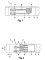
- Figure 1 a section of a test media tape with a test media portion having two electrodes and two contact fields is shown.
- the test media tape 1 comprises a tape 2 and a test media portion 3.
- the test media portion 3 contains two electrodes 4 and 4', which are positioned in a sensor field (not shown).
- the two electrodes 4 and 4' are electrically connected (via conductors 6 and 6') to two contact fields 5 and 5', which are to be electrically contacted by means of a roller (not shown) within a fluid testing device according to the present invention.
- the test media tape has a plurality of sections as shown in Figure 1 .
- the test media tape 1 comprises a tape 2 and a test media portion 3.
- the test media portion 3 contains a sensor field 7, in which electrodes (not shown) are arranged.
- the electrodes are connected via conductors 6 to four contact fields 5, which are arranged two by two in a first row 8 and a second row 9, the rows 8, 9 being arranged in a transverse direction 10 of the test media tape 1.
- the contact fields within the two rows 8, 9 are shifted to one another in the transverse direction 10, so that they do not lie in one line in the longitudinal direction 11 of the test media tape 1.
- a test media tape 1 to be used in a sample fluid testing device according to the present invention comprises a plurality of sections as shown in Figure 2 .
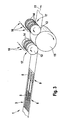
- the test media tape 1 comprising a plurality of test media portions 3 (only one shown in Figure 3 ) is movable within the sample fluid testing device in the longitudinal direction 11.
- Each test media portion 3 comprises (in this case) five contact fields 5, which are arranged in two rows 8, 9 and which are to be electrically contacted.
- Two rollers 12, 13 are provided for contacting the contact fields 5.
- the first roller 12 contains two annular contact zones 14 and the second roller 13 contains three annular contact zones 14 on the surface 17. Both rollers 12, 13 are in rolling engagement with the test media tape 1.
- An elastic roll 15 is arranged on the side of the test media tape 1 opposite the side with the rollers 12, 13 to produce a contact pressure of the test media tape 1 against the rollers 12, 13.
- the rollers 12, 13 and the elastic roll 15 roll along the two surfaces of the test media tape 1 in different rotating directions.
- the rollers 12, 13 reach a test media portion 3
- the first roller 12 electrically contacts the two contact fields 5 in the first row 8 with its two contact zones 14
- the second roller 13 electrically contacts the three contact fields 5 in the second row 9 with its three contact zones 14.
- the contact zones 14 of both rollers 12, 13 are electrically connected to a meter (not shown) by sliding contacts 16.
Description
- The present invention refers to a sample fluid testing device and a method for analyzing a sample fluid, using a test media tape.
- Sample fluid testing devices are used e.g. by diabetics for regularly testing samples of their blood to determine the level of blood glucose. In one known type of fluid testing devices, disposable test strips are used to test the sample fluid, each test strip comprising a sensor field, which contains a reagent material that will react with an analyte within the sample fluid. One possibility well-known in the art for analyzing the sample fluid on the sensor field is an electrochemical analysis. For the electrochemical analysis, electrical signals produced within the sensor field which contains the sample fluid are relayed from electrodes within the sensor field to a meter via electrically conductive tracks, the meter being part of the sample fluid testing device. After the measurement has been taken, the test strip is disposed of.
- Other known types of fluid testing devices contain test media cassettes with a plurality of sensor fields on a test media tape, the test media tape being provided on a reel within the test media cassette.
-
WO 2004/056269 A1 is directed towards a body fluid testing device for analyzing a body fluid, comprising: a test media tape adapted to collect the body fluid, said test media tape comprising a tape and test media portions, wherein a free tape portion without test medium is located between successive test media portions. The testing device further comprises a supply portion, which comprises a housing in which an uncontaminated test media tape is contained, the housing further having an opening for withdrawing the test media tape from the housing. The supply portion further has a sealing means for closing the opening against the surrounding. A free tape portion of the test media tape is located between a surface (typically a wall of the housing) and the sealing means when the sealing means closes the opening. -
EP 1 424 040 A1WO01/73109 WO01/23885 - For electrochemically analyzing a sample fluid on such a test media tape, an electrical contact from a meter within the sample fluid testing device to the sensor fields on the test media tape has to be established. One known solution for establishing this contact is e.g. described in
WO 01/23885 A1 - Another example for a sample fluid testing device with such a solution for the electrical contact between the sensor fields and the meter is described in
US 2005/0230253 A1 andWO99/09621 - One disadvantage of this solution is that the long conductive track connecting the electrodes of adjacent sensors has a high resistance, which above all is altered, when the individual sensors are separated from the reel. Furthermore, the unused sensors are not totally passive and can produce interfering signals, which are not related to the analyzed sample fluid. Moreover, the separated sensors are contaminated with the sample fluid and have to be safely discarded, whereas a continuous test media tape, from which the used sensors are not separated, could be stored conveniently on a reel within a waste portion of the test media cassette.
-
US 5,395,504 A therefore proposes a test media tape with a plurality of separately arranged sensors, which are contacted successively. The contact of each sensor with an electronic circuit is provided by means of resilient foils coming into contact with zones of contact of the sensor by means of a slide connection. One drawback of a slide connection is, that the sliding of the slide contacts over the surface of the moving test media tape when the next sensor is to be used can damage the elements on the surface of the test media tape, e.g. electrodes or conductive tracks made of very thin metal layers (approximately 50 nm). -
WO 2005/047861 A2 discloses a biochemical analysis instrument for multiple fluid analysis including a housing, a sensor for sensing a reaction disposed in the housing, an aperture formed in the housing and a test tape housing area formed in the housing. The sensor is disposed to selectively move within the housing area, the aperture being formed to provide access to this tape housing area. The instrument further includes a cassette configured to be received within the tape housing area. The cassette includes a case, a first chamber formed in the case, a second chamber formed in the case, a gap formed in the case, wherein the first chamber and the second chamber are disposed at a respective side of the gap. A test tape is disposed within the housing, which extends from the first chamber across the gap to the second chamber, the test tape having a plurality of active zones disposed at predetermined spaced intervals along the tape for testing an analyte. An electrode based sensor head can be moved forward to contact the test tape and retracted into its original lower non-contact position. Such a solution for contacting the sensors requires a complex construction of the sample fluid testing device to enable the movement of the sensor head and the test tape and to detect their relative positions. - The present invention is therefore based on the object of avoiding the disadvantages of the prior art and especially of presenting a sample fluid testing device, which allows a safe and easy establishment of an electrical contact of a meter with the electrodes within a sensor field on a test media tape.
- These objects are achieved by a sample fluid testing device for analyzing a sample fluid, comprising a test media tape comprising a tape and plurality of test media portions. Each test media portion contains a sensor field for producing electrical signals when the sample fluid is applied. The test media portions further contain at least two electrodes, the at least two electrodes being positioned in the sensor field and being electrically connected to at least two contact fields on the test media portion. The sample fluid testing device further comprises at least one roller with a surface which contains at least one contact zone. The at least one roller is in rolling engagement with the test media tape with its surface in order to successively electrically contact the test media portions via at least one contact field with the at least one contact zone. The at least one contact zone on the at least one roller is electrically connected to a meter for measuring the electrical signals.
- The sample fluid testing device can be provided for analyzing sample fluids selected from the group of body fluids, environmental samples, food samples or the like. Preferably, the sample fluid testing device according to the invention determines the concentration of glucose in blood samples.
- The sample fluid testing device comprises a test media tape. This test media tape contains a tape, which is an elongate band used as a carrier for the test media portions. Preferably, the tape is made of an electrically insulating, non hygroscopic material, e.g. plastic foils from polyester, polycarbonate, cellulose derivatives and polystyrene. The test media portions of the test media tape are separate testing elements, which are arranged successively and preferably spaced to one another on the tape. They can be produced in the form of labels, which are fixed to the tape by an adhesive layer. Preferably, a free tape portion is located between successive test media portions of the test media tape. The test media portions each contain a sensor field, which may contain a reagent material and in which the sample fluid is analyzed electrochemically. For this purpose, each sensor field contains at least two electrodes. The at least two electrodes are electrically connected to at least two contact fields, which are also arranged on the test media portion. The contact fields are provided for electrically contacting the electrodes of the sensor field with connecting elements of a meter for measuring electrical signals produced in the sensor field. According to the present invention, the sample fluid testing device comprises at least one roller for establishing the electrical contact between the contact fields and the meter. The surface of this roller (which is preferably cylindrical) contains at least one (electrically conducting) contact zone. This contact zone is preferably surrounded by insulating material on the surface of the roller. The at least one roller is in rolling engagement with the test media tape with its surface. Preferably, the roller rolls along the surface of the test media tape in a longitudinal direction when the test media tape is moved to its next testing position, in which the sample fluid can be applied to the next media portion, while the roller does not change its position within the sample fluid testing device. The roller is arranged to electrically contact successively the test media portions via their contact fields, when the at least one contact zone of the roller meets a contact field on the test media tape surface. By establishing this contact, electrical signals produced in the sensor field can be conducted from the electrodes via the contact field and the contact zone to a meter for measuring these signals, the contact zone of the roller being electrically connected to the meter. The meter preferably contains means for evaluating the measured electrical signals, e.g. to determine the concentration of an analyte within the sample fluid, and means for displaying an analysis result to the user of the sample fluid testing device.
- The present invention further refers to a method for analyzing a sample fluid, wherein the sample fluid is analyzed on a test media tape, the test media tape comprising a plurality of test media portions, each test media portion containing a sensor field for producing electrical signals when the sample fluid is applied and at least two electrodes. The at least two electrodes are positioned in the sensor field and are electrically connected to at least one contact field of the test media portion. The method comprises the steps of applying a sample fluid to the sensor field of a test media portion and of rolling at least one roller with a surface, which contains at least one contact zone, along the test media tape, in order to electrically contact the contact fields of the test media portion with the at least one contact zone. Furthermore, it comprises measuring the electrical signal produced within the sensor field with a meter, which is electrically connected to the at least one contact zone of the roller. This method is preferably carried out using a sample fluid testing device according to the present invention. The analyzed sample fluid is preferably selected from the group of body fluid, environmental sample and food sample. The order of applying the sample fluid and electrically contacting the contact fields by means of the roller can be freely chosen.
- The present invention further refers to a method for preparing a sample fluid testing device for analyzing a sample fluid, wherein the sample fluid is analyzed on a test media tape, the test media tape comprising a plurality of test media portions, each test media portion containing a sensor field for producing electrical signals, when the sample fluid is applied, and at least two electrodes, the at least two electrodes being positioned in the sensor field and being electrically connected to at least two contact fields of the test media portion. According to this method, at least one roller is rolled with its surface, which contains at least one contact zone, along the test media tape, in order to electrically contact the contact fields of the test media portion with the at least one contact zone, which is electrically connected to a meter. When this contact is established, the sample fluid testing device is prepared to analyze a sample fluid electrochemically in the sensor field of the contacted test media portion.
- One advantage of the device and the method according to the present invention is, that an electrical contact between a meter and an individual test media portion of a test media tape can be established without scratching over the surface of the test media tape and without a complicated mechanism for placing an electrical contact element exactly on the contact fields of the test media portion.
- According to a preferred embodiment of the present invention, the at least one contact zone of the at least one roller is electrically connected to the meter by a sliding contact. Thereby, the functions of contacting the contact fields on the movable test media tape and of connecting the rotatable roller to the immobile meter are separated.
- According to a preferred embodiment of the present invention, the at least one contact zone is an electrically conducting annular zone arranged on the circumference of the surface of the roller. Such a roller can be produced by stacking alternately round discs of a conducting material and round discs of an insulating material and joining them to form a cylindrical roller. The round discs of conducting material will then form annular contact zones on the surface of the roller, flanked by annular non conducting zones formed by the discs of insulating material. The contact zones of the roller can also be produced by coating selected zones (e.g. annular zones) on the surface of a roller with a conducting material (e.g. a metal), the roller consisting of an insulating material.
- In the sample fluid testing device according to the invention, the contact fields can be arranged in at least two rows on the test media portion, the rows being arranged in a transverse direction of the test media tape and the contact fields within two different rows being shifted to one another in the transverse direction. This arrangement is especially favourable if a plurality of contact fields is required for each test media portion. In this case, the contact fields would have to be very narrow if they were all placed side by side on the test media tape, making their production and contacting difficult. By placing the contact fields in rows and shifted to one another, this problem can be overcome. The contact fields in the at least two rows can be contacted by one roller, which is in rolling engagement successively with the each row of contact fields. The contact fields in the at least two rows can also be contacted by at least two rollers, which are arranged next to each other and which can be in rolling engagement at the same time with at least two rows of contact fields.
- Preferably, at least one counter roll is arranged on one side of the test media tape for producing a contact pressure of the test media tape against the at least one roller on the other side of the test media tape. This can be an elastic roll or a roll being pressed by an elastic element (e.g. a spring) against the other side of the test media tape.
- According to a preferred embodiment of the present invention, the test media tape is housed in a cassette. The cassette is used for storing the test media tape within the sample fluid testing device. After all test media tape portions of one cassette are used up, preferably a new test media cassette with uncontaminated test media portions on a test media tape can be inserted into the sample fluid testing device. The unused and/or the used test media tape can be stored within the cassette on a reel.
- Preferably, the cassette comprises a supply portion for storing unused test media tape, the supply portion having a port for withdrawing test media tape from the supply portion and said supply portion further having sealing means for closing the port in a first position of the sealing means and for opening the port in a second position of the sealing means. The sealing means is provided for preventing the entry of humidity and/or contaminants into the supply portion of the cassette. The port, by which the test media tape can be withdrawn, can be opened and closed by the sealing means. Preferably, it is opened, when the test media tape is moved, in order not to damage any components of the test media tape, e.g. the sensor field or thin conducting metal layers, by squeezing it through the sealing means. The opening and closing can be effected automatically or manually. The automatic operation of the sealing means can include, for example, the use of hydraulic means.
- Preferably, the automatic operation of the sealing means is coupled to a position identification means, the port being opened by the sealing means when the position identification means identifies a first position of the test media tape within the sample fluid testing device and the sealing means closing the port when the position identification means identifies a second position. Preferably, the port is closed by the sealing means only when the sealing means is positioned at a free tape portion of the test media tape. The position identification means can be coupled to at least one of the contact zones on the roller. When this contact zone contacts a contact field on the test media tape, which can be provided especially for this function, a certain position of the test media tape is identified. According to a preferred embodiment of the present invention, the test media tape is advanced by a drive means, rolling the roller passively or actively along the test media tape, the drive means advancing the test media tape until the at least one contact zone of at least one roller electrically contacts certain contact fields of a test media portion.
- According to a preferred embodiment of the present invention, a cassette with a supply portion for storing unused test media tape further comprises a waste portion for receiving a test media tape that is contaminated with the sample fluid.
- The present invention is explained in greater detail below with reference to the drawings.
-
Figure 1 shows schematically a section of a first test media tape, which can be used for the present invention, -
Figure 2 shows schematically a section of a second test media tape, which can be used for the present invention and -
Figure 3 shows schematically two rollers in rolling engagement with a test media tape in a sample fluid testing device according to the present invention. - In
Figure 1 , a section of a test media tape with a test media portion having two electrodes and two contact fields is shown. - The
test media tape 1 comprises atape 2 and atest media portion 3. Thetest media portion 3 contains twoelectrodes 4 and 4', which are positioned in a sensor field (not shown). The twoelectrodes 4 and 4' are electrically connected (viaconductors 6 and 6') to twocontact fields 5 and 5', which are to be electrically contacted by means of a roller (not shown) within a fluid testing device according to the present invention. The test media tape has a plurality of sections as shown inFigure 1 . - In
Figure 2 , a section of another test media tape with a test media portion having a sensor field and four contact fields is shown. - The
test media tape 1 comprises atape 2 and atest media portion 3. Thetest media portion 3 contains asensor field 7, in which electrodes (not shown) are arranged. The electrodes are connected viaconductors 6 to fourcontact fields 5, which are arranged two by two in a first row 8 and asecond row 9, therows 8, 9 being arranged in atransverse direction 10 of thetest media tape 1. The contact fields within the tworows 8, 9 are shifted to one another in thetransverse direction 10, so that they do not lie in one line in thelongitudinal direction 11 of thetest media tape 1. Atest media tape 1 to be used in a sample fluid testing device according to the present invention comprises a plurality of sections as shown inFigure 2 . - In
Figure 3 , two rollers of a sample fluid testing device according to the present invention are shown in rolling engagement with a test media tape. - The
test media tape 1 comprising a plurality of test media portions 3 (only one shown inFigure 3 ) is movable within the sample fluid testing device in thelongitudinal direction 11. Eachtest media portion 3 comprises (in this case) fivecontact fields 5, which are arranged in tworows 8, 9 and which are to be electrically contacted. Tworollers first roller 12 contains twoannular contact zones 14 and thesecond roller 13 contains threeannular contact zones 14 on thesurface 17. Bothrollers test media tape 1. Anelastic roll 15 is arranged on the side of thetest media tape 1 opposite the side with therollers test media tape 1 against therollers test media tape 1 is moved in thelongitudinal direction 11, therollers elastic roll 15 roll along the two surfaces of thetest media tape 1 in different rotating directions. When therollers test media portion 3, thefirst roller 12 electrically contacts the twocontact fields 5 in the first row 8 with its twocontact zones 14 and thesecond roller 13 electrically contacts the threecontact fields 5 in thesecond row 9 with its threecontact zones 14. Thecontact zones 14 of bothrollers contacts 16. -
- 1
- test media tape
- 2
- tape
- 3
- test media portion
- 4, 4'
- electrodes
- 5, 5'
- contact fields
- 6, 6'
- conductors
- 7
- sensor field
- 8
- first row
- 9
- second row
- 10
- transverse direction
- 11
- longitudinal direction
- 12
- first roller
- 13
- second roller
- 14
- contact zones
- 15
- elastic roll
- 16
- sliding contacts
- 17
- surface
Claims (9)
- A sample fluid testing device for analyzing a sample fluid, comprising a test media tape (1) comprising a tape (2) and a plurality of test media portions (3), each test media portion (3) containing a sensor field (7) for producing electrical signals when the sample fluid is applied; and at least two electrodes (4), the at least two electrodes (4) being positioned in the sensor field (7) and being electrically connected to at least two contact fields (5) on the test media portion (3), characterized by at least one roller (12, 13) with a surface (17), which contains at least one contact zone (14), wherein the at least one contact zone (14) is a plurality of electrically conducting annular zones arranged on the circumference of the surface (17) of the roller (12, 13), the at least one roller (12, 13) being in rolling engagement with the test media tape (1) with its surface (17) in order to successively electrically contact the test media portions (3) via the at least two contact fields (5) with the at least one contact zone (14), wherein the sample fluid testing device further comprises a meter, the at least one contact zone (14) on the at least one roller (12, 13) being electrically connected to the meter for measuring the electrical signals.
- The sample fluid testing device according to claim 1, wherein at least one contact zone (14) of the at least one roller (12, 13) is electrically connected to the meter by a sliding contact (16).
- The sample fluid testing device according to any of claims 1 to 2, wherein the contact fields (5) are arranged in at least two rows (8, 9), the rows (8, 9) being arranged in a transverse direction (10) of the test media tape (1) and the contact fields (5) within two different rows (8, 9) being shifted to one another in the transverse direction (10).
- The sample fluid testing device according to any of claims 1 to 3, wherein at least one counter roll (15) is arranged on one side of the test media tape (1) for producing a contact pressure of the test media tape (1) against at least one roller (12, 13) on the other side of the test media tape (1).
- The sample fluid, testing device according to any of claims 1 to 4, wherein the test media tape (1) is housed in a cassette.
- The sample fluid testing device according to claim 5, wherein the cassette comprises a supply portion for storing unused test media tape, the supply portion having a port for withdrawing test media tape (1) from the supply portion and said supply portion further having sealing means for closing said port in a first position of the sealing means and for opening said port in a second position of the sealing means.
- The sample fluid testing device according to claim 6, wherein the cassette comprises a waste portion for receiving test media tape that is contaminated with the sample fluid.
- A method for analyzing a sample fluid, wherein the sample fluid is analyzed on a test media tape (1), the test media tape comprising a plurality of test media portions (3),
each test media portion containing a sensor field for producing electrical signals when the sample fluid is applied and at least two electrodes (4), the at least two electrodes being positioned in the sensor field (7) and being electrically connected to at least two contact fields (5) of the test media portion, characterized by applying a sample fluid to the test field of a test media portion and rolling at least one roller (12, 13) with a surface, which contains at least one contact zone (14), wherein the at least one contact zone (14) is a plurality of electrically conducting annular zones arranged on the circumference of the surface (17) of the roller (12, 13), along the test media tape, in order to electrically contact the contact fields of the test media portion with the at least one contact zone and measuring the electrical signals produced within the sensor field with a meter, which is electrically connected to the at least one contact zone of the roller. - The method according to claim 8, wherein the test media tape is advanced by a drive means, rolling the roller along the test media tape, the drive means advancing the test media tape until the at least one contact zone of the at least one roller electrically contacts certain contact fields on a test media portion.
Applications Claiming Priority (2)
| Application Number | Priority Date | Filing Date | Title |
|---|---|---|---|
| US74609406P | 2006-05-01 | 2006-05-01 | |
| PCT/EP2007/054213 WO2007125121A1 (en) | 2006-05-01 | 2007-04-30 | Rolling contactor for electrically connecting a meter with a sensing element |
Publications (2)
| Publication Number | Publication Date |
|---|---|
| EP2016403A1 EP2016403A1 (en) | 2009-01-21 |
| EP2016403B1 true EP2016403B1 (en) | 2012-11-07 |
Family
ID=38336842
Family Applications (1)
| Application Number | Title | Priority Date | Filing Date |
|---|---|---|---|
| EP07728667A Not-in-force EP2016403B1 (en) | 2006-05-01 | 2007-04-30 | Rolling contactor for electrically connecting a meter with a sensing element |
Country Status (6)
| Country | Link |
|---|---|
| US (1) | US8685227B2 (en) |
| EP (1) | EP2016403B1 (en) |
| JP (1) | JP4906918B2 (en) |
| CN (1) | CN101432623A (en) |
| CA (1) | CA2650759C (en) |
| WO (1) | WO2007125121A1 (en) |
Families Citing this family (6)
| Publication number | Priority date | Publication date | Assignee | Title |
|---|---|---|---|---|
| DE102005013685A1 (en) | 2005-03-18 | 2006-09-28 | Roche Diagnostics Gmbh | Tape magazine for a hand-held device for examining a body fluid, as well as a hand-held device |
| GB2469070A (en) * | 2009-03-31 | 2010-10-06 | Diamatrix Ltd | Test material and cassette for bio-sensing |
| US20110057671A1 (en) * | 2009-09-04 | 2011-03-10 | Lifescan Scotland, Ltd. | Methods, system and device to identify a type of test strip |
| JP2013545109A (en) * | 2010-12-09 | 2013-12-19 | ケヴァル,アルテュール | Microfluidic devices for fluid sample analysis |
| WO2013038691A1 (en) * | 2011-09-14 | 2013-03-21 | パナソニック株式会社 | Biological information detection sensor supply device |
| CN115633970B (en) * | 2022-12-19 | 2023-06-06 | 浙江强脑科技有限公司 | Portable physiological signal monitoring device and physiological signal monitoring method |
Family Cites Families (28)
| Publication number | Priority date | Publication date | Assignee | Title |
|---|---|---|---|---|
| US3322513A (en) * | 1965-10-04 | 1967-05-30 | Metaltronics Inc | Sintered carbides |
| US3703368A (en) * | 1970-11-03 | 1972-11-21 | Teledyne Ind | Method for making castable carbonitride alloys |
| GB1379556A (en) * | 1971-04-27 | 1975-01-02 | Lucas Industries Ltd | Method of extruding a metal component using a die and punch set |
| US3901061A (en) * | 1971-04-27 | 1975-08-26 | Lucas Industries Ltd | Die and punch sets |
| JPS5075511A (en) * | 1973-11-09 | 1975-06-20 | ||
| US4290807A (en) * | 1977-09-20 | 1981-09-22 | Sumitomo Electric Industries, Ltd. | Hard alloy and a process for the production of the same |
| US4228673A (en) * | 1978-10-06 | 1980-10-21 | Carmet Company | Die assembly and method of making the same |
| DE3264742D1 (en) * | 1981-04-06 | 1985-08-22 | Mitsubishi Metal Corp | Tungsten carbide-base hard alloy for hot-working apparatus members |
| US4628178A (en) * | 1984-05-29 | 1986-12-09 | Sumitomo Electric Industries, Ltd. | Tool for warm and hot forgings and process for manufacturing the same |
| DE68921438T2 (en) * | 1988-12-13 | 1995-09-14 | Daikin Ind Ltd | Test device for measuring the concentration of a test substance in a liquid. |
| JP2854388B2 (en) * | 1990-06-07 | 1999-02-03 | 三井造船株式会社 | Water control method for dewatered sludge |
| DE4123348A1 (en) * | 1991-07-15 | 1993-01-21 | Boehringer Mannheim Gmbh | ELECTROCHEMICAL ANALYSIS SYSTEM |
| ATE173030T1 (en) * | 1991-09-02 | 1998-11-15 | Sumitomo Electric Industries | HARD ALLOY AND THEIR PRODUCTION |
| JPH06222035A (en) * | 1992-03-28 | 1994-08-12 | Japan Vilene Co Ltd | Detecting region carrying tape, detecting element, detector and detecting system |
| FR2701117B1 (en) | 1993-02-04 | 1995-03-10 | Asulab Sa | Electrochemical measurement system with multizone sensor, and its application to glucose measurement. |
| US6040705A (en) * | 1997-08-20 | 2000-03-21 | Electro Scientific Industries, Inc. | Rolling electrical contactor |
| JP4256094B2 (en) * | 1999-09-27 | 2009-04-22 | ハイポガード リミテッド | Test equipment |
| DK1311702T3 (en) * | 2000-03-28 | 2006-03-27 | Diabetes Diagnostics Inc | Continuous process for producing a disposable electrochemical sensing element |
| US6827899B2 (en) * | 2000-08-30 | 2004-12-07 | Hypoguard Limited | Test device |
| JP4522014B2 (en) * | 2001-04-18 | 2010-08-11 | パナソニック株式会社 | Biosensor sheet, biosensor cartridge, and biosensor dispensing device |
| JP4618953B2 (en) * | 2001-09-13 | 2011-01-26 | パナソニック株式会社 | Biosensor sheet, biosensor cartridge, and biosensor dispensing device |
| WO2003089917A1 (en) * | 2002-04-19 | 2003-10-30 | Matsushita Electric Industrial Co., Ltd. | Biosensor cartridge and biosensor dispensing device |
| DE10244775A1 (en) | 2002-09-26 | 2004-04-08 | Roche Diagnostics Gmbh | Capillary sensor analysis system |
| EP1424040A1 (en) | 2002-11-26 | 2004-06-02 | Roche Diagnostics GmbH | Body fluid testing device |
| EP2289416B1 (en) | 2002-12-23 | 2014-08-20 | Roche Diagnostics GmbH | Body fluid testing device |
| US7718439B2 (en) * | 2003-06-20 | 2010-05-18 | Roche Diagnostics Operations, Inc. | System and method for coding information on a biosensor test strip |
| US7378270B2 (en) | 2003-11-10 | 2008-05-27 | Sentec Scientific, Inc. | Device for analyte measurement |
| TWI440453B (en) * | 2004-02-18 | 2014-06-11 | Universal Biosensors Pty Ltd | Strip ejection system |
-
2007
- 2007-04-30 CA CA2650759A patent/CA2650759C/en not_active Expired - Fee Related
- 2007-04-30 CN CNA2007800156785A patent/CN101432623A/en active Pending
- 2007-04-30 EP EP07728667A patent/EP2016403B1/en not_active Not-in-force
- 2007-04-30 JP JP2009508328A patent/JP4906918B2/en not_active Expired - Fee Related
- 2007-04-30 WO PCT/EP2007/054213 patent/WO2007125121A1/en active Application Filing
-
2008
- 2008-10-24 US US12/257,960 patent/US8685227B2/en active Active
Also Published As
| Publication number | Publication date |
|---|---|
| JP2009535630A (en) | 2009-10-01 |
| US20090095641A1 (en) | 2009-04-16 |
| US8685227B2 (en) | 2014-04-01 |
| WO2007125121A1 (en) | 2007-11-08 |
| CN101432623A (en) | 2009-05-13 |
| CA2650759C (en) | 2011-11-22 |
| CA2650759A1 (en) | 2007-11-08 |
| EP2016403A1 (en) | 2009-01-21 |
| JP4906918B2 (en) | 2012-03-28 |
Similar Documents
| Publication | Publication Date | Title |
|---|---|---|
| US8685227B2 (en) | Sample fluid testing device and method for analyzing a sample fluid | |
| CA2708845C (en) | Blood glucose sensor | |
| CA2529302C (en) | System and method for coding information on a biosensor test strip | |
| US7718439B2 (en) | System and method for coding information on a biosensor test strip | |
| US7645421B2 (en) | System and method for coding information on a biosensor test strip | |
| US8206565B2 (en) | System and method for coding information on a biosensor test strip | |
| US20050019945A1 (en) | System and method for coding information on a biosensor test strip | |
| US20050016846A1 (en) | System and method for coding information on a biosensor test strip | |
| EP2122345A1 (en) | Analyte-testing instruments | |
| JP2009535630A5 (en) | ||
| US20170016876A1 (en) | Device and method for unit use sensor testing | |
| US20050121826A1 (en) | Multi-sensor device for motorized meter and methods thereof | |
| CN113899801A (en) | Test element for electrochemically detecting at least one analyte |
Legal Events
| Date | Code | Title | Description |
|---|---|---|---|
| PUAI | Public reference made under article 153(3) epc to a published international application that has entered the european phase |
Free format text: ORIGINAL CODE: 0009012 |
|
| 17P | Request for examination filed |
Effective date: 20081124 |
|
| AK | Designated contracting states |
Kind code of ref document: A1 Designated state(s): AT BE BG CH CY CZ DE DK EE ES FI FR GB GR HU IE IS IT LI LT LU LV MC MT NL PL PT RO SE SI SK TR |
|
| AX | Request for extension of the european patent |
Extension state: AL BA HR MK RS |
|
| REG | Reference to a national code |
Ref country code: DE Ref legal event code: R079 Ref document number: 602007026540 Country of ref document: DE Free format text: PREVIOUS MAIN CLASS: G01N0033000000 Ipc: H01R0039640000 |
|
| RIC1 | Information provided on ipc code assigned before grant |
Ipc: H01R 39/64 20060101AFI20120314BHEP Ipc: G01N 33/487 20060101ALI20120314BHEP |
|
| DAX | Request for extension of the european patent (deleted) | ||
| GRAP | Despatch of communication of intention to grant a patent |
Free format text: ORIGINAL CODE: EPIDOSNIGR1 |
|
| RAP1 | Party data changed (applicant data changed or rights of an application transferred) |
Owner name: F.HOFFMANN-LA ROCHE AG Owner name: ROCHE DIAGNOSTICS GMBH |
|
| GRAS | Grant fee paid |
Free format text: ORIGINAL CODE: EPIDOSNIGR3 |
|
| GRAA | (expected) grant |
Free format text: ORIGINAL CODE: 0009210 |
|
| AK | Designated contracting states |
Kind code of ref document: B1 Designated state(s): AT BE BG CH CY CZ DE DK EE ES FI FR GB GR HU IE IS IT LI LT LU LV MC MT NL PL PT RO SE SI SK TR |
|
| REG | Reference to a national code |
Ref country code: GB Ref legal event code: FG4D |
|
| REG | Reference to a national code |
Ref country code: AT Ref legal event code: REF Ref document number: 583329 Country of ref document: AT Kind code of ref document: T Effective date: 20121115 Ref country code: CH Ref legal event code: EP |
|
| REG | Reference to a national code |
Ref country code: IE Ref legal event code: FG4D |
|
| REG | Reference to a national code |
Ref country code: DE Ref legal event code: R096 Ref document number: 602007026540 Country of ref document: DE Effective date: 20130103 |
|
| REG | Reference to a national code |
Ref country code: AT Ref legal event code: MK05 Ref document number: 583329 Country of ref document: AT Kind code of ref document: T Effective date: 20121107 |
|
| REG | Reference to a national code |
Ref country code: NL Ref legal event code: VDEP Effective date: 20121107 |
|
| REG | Reference to a national code |
Ref country code: LT Ref legal event code: MG4D |
|
| PG25 | Lapsed in a contracting state [announced via postgrant information from national office to epo] |
Ref country code: FI Free format text: LAPSE BECAUSE OF FAILURE TO SUBMIT A TRANSLATION OF THE DESCRIPTION OR TO PAY THE FEE WITHIN THE PRESCRIBED TIME-LIMIT Effective date: 20121107 Ref country code: NL Free format text: LAPSE BECAUSE OF FAILURE TO SUBMIT A TRANSLATION OF THE DESCRIPTION OR TO PAY THE FEE WITHIN THE PRESCRIBED TIME-LIMIT Effective date: 20121107 Ref country code: SE Free format text: LAPSE BECAUSE OF FAILURE TO SUBMIT A TRANSLATION OF THE DESCRIPTION OR TO PAY THE FEE WITHIN THE PRESCRIBED TIME-LIMIT Effective date: 20121107 Ref country code: LT Free format text: LAPSE BECAUSE OF FAILURE TO SUBMIT A TRANSLATION OF THE DESCRIPTION OR TO PAY THE FEE WITHIN THE PRESCRIBED TIME-LIMIT Effective date: 20121107 Ref country code: IS Free format text: LAPSE BECAUSE OF FAILURE TO SUBMIT A TRANSLATION OF THE DESCRIPTION OR TO PAY THE FEE WITHIN THE PRESCRIBED TIME-LIMIT Effective date: 20130307 |
|
| PG25 | Lapsed in a contracting state [announced via postgrant information from national office to epo] |
Ref country code: BE Free format text: LAPSE BECAUSE OF FAILURE TO SUBMIT A TRANSLATION OF THE DESCRIPTION OR TO PAY THE FEE WITHIN THE PRESCRIBED TIME-LIMIT Effective date: 20121107 Ref country code: PT Free format text: LAPSE BECAUSE OF FAILURE TO SUBMIT A TRANSLATION OF THE DESCRIPTION OR TO PAY THE FEE WITHIN THE PRESCRIBED TIME-LIMIT Effective date: 20130307 Ref country code: PL Free format text: LAPSE BECAUSE OF FAILURE TO SUBMIT A TRANSLATION OF THE DESCRIPTION OR TO PAY THE FEE WITHIN THE PRESCRIBED TIME-LIMIT Effective date: 20121107 Ref country code: SI Free format text: LAPSE BECAUSE OF FAILURE TO SUBMIT A TRANSLATION OF THE DESCRIPTION OR TO PAY THE FEE WITHIN THE PRESCRIBED TIME-LIMIT Effective date: 20121107 Ref country code: GR Free format text: LAPSE BECAUSE OF FAILURE TO SUBMIT A TRANSLATION OF THE DESCRIPTION OR TO PAY THE FEE WITHIN THE PRESCRIBED TIME-LIMIT Effective date: 20130208 Ref country code: CY Free format text: LAPSE BECAUSE OF FAILURE TO SUBMIT A TRANSLATION OF THE DESCRIPTION OR TO PAY THE FEE WITHIN THE PRESCRIBED TIME-LIMIT Effective date: 20121107 Ref country code: LV Free format text: LAPSE BECAUSE OF FAILURE TO SUBMIT A TRANSLATION OF THE DESCRIPTION OR TO PAY THE FEE WITHIN THE PRESCRIBED TIME-LIMIT Effective date: 20121107 |
|
| PG25 | Lapsed in a contracting state [announced via postgrant information from national office to epo] |
Ref country code: AT Free format text: LAPSE BECAUSE OF FAILURE TO SUBMIT A TRANSLATION OF THE DESCRIPTION OR TO PAY THE FEE WITHIN THE PRESCRIBED TIME-LIMIT Effective date: 20121107 |
|
| PG25 | Lapsed in a contracting state [announced via postgrant information from national office to epo] |
Ref country code: DK Free format text: LAPSE BECAUSE OF FAILURE TO SUBMIT A TRANSLATION OF THE DESCRIPTION OR TO PAY THE FEE WITHIN THE PRESCRIBED TIME-LIMIT Effective date: 20121107 Ref country code: CZ Free format text: LAPSE BECAUSE OF FAILURE TO SUBMIT A TRANSLATION OF THE DESCRIPTION OR TO PAY THE FEE WITHIN THE PRESCRIBED TIME-LIMIT Effective date: 20121107 Ref country code: SK Free format text: LAPSE BECAUSE OF FAILURE TO SUBMIT A TRANSLATION OF THE DESCRIPTION OR TO PAY THE FEE WITHIN THE PRESCRIBED TIME-LIMIT Effective date: 20121107 Ref country code: EE Free format text: LAPSE BECAUSE OF FAILURE TO SUBMIT A TRANSLATION OF THE DESCRIPTION OR TO PAY THE FEE WITHIN THE PRESCRIBED TIME-LIMIT Effective date: 20121107 Ref country code: BG Free format text: LAPSE BECAUSE OF FAILURE TO SUBMIT A TRANSLATION OF THE DESCRIPTION OR TO PAY THE FEE WITHIN THE PRESCRIBED TIME-LIMIT Effective date: 20130207 |
|
| PG25 | Lapsed in a contracting state [announced via postgrant information from national office to epo] |
Ref country code: IT Free format text: LAPSE BECAUSE OF FAILURE TO SUBMIT A TRANSLATION OF THE DESCRIPTION OR TO PAY THE FEE WITHIN THE PRESCRIBED TIME-LIMIT Effective date: 20121107 Ref country code: RO Free format text: LAPSE BECAUSE OF FAILURE TO SUBMIT A TRANSLATION OF THE DESCRIPTION OR TO PAY THE FEE WITHIN THE PRESCRIBED TIME-LIMIT Effective date: 20121107 |
|
| PLBE | No opposition filed within time limit |
Free format text: ORIGINAL CODE: 0009261 |
|
| STAA | Information on the status of an ep patent application or granted ep patent |
Free format text: STATUS: NO OPPOSITION FILED WITHIN TIME LIMIT |
|
| 26N | No opposition filed |
Effective date: 20130808 |
|
| PG25 | Lapsed in a contracting state [announced via postgrant information from national office to epo] |
Ref country code: ES Free format text: LAPSE BECAUSE OF FAILURE TO SUBMIT A TRANSLATION OF THE DESCRIPTION OR TO PAY THE FEE WITHIN THE PRESCRIBED TIME-LIMIT Effective date: 20130218 |
|
| PG25 | Lapsed in a contracting state [announced via postgrant information from national office to epo] |
Ref country code: MC Free format text: LAPSE BECAUSE OF FAILURE TO SUBMIT A TRANSLATION OF THE DESCRIPTION OR TO PAY THE FEE WITHIN THE PRESCRIBED TIME-LIMIT Effective date: 20121107 |
|
| REG | Reference to a national code |
Ref country code: CH Ref legal event code: PL |
|
| REG | Reference to a national code |
Ref country code: DE Ref legal event code: R097 Ref document number: 602007026540 Country of ref document: DE Effective date: 20130808 |
|
| GBPC | Gb: european patent ceased through non-payment of renewal fee |
Effective date: 20130430 |
|
| REG | Reference to a national code |
Ref country code: IE Ref legal event code: MM4A |
|
| PG25 | Lapsed in a contracting state [announced via postgrant information from national office to epo] |
Ref country code: CH Free format text: LAPSE BECAUSE OF NON-PAYMENT OF DUE FEES Effective date: 20130430 Ref country code: LI Free format text: LAPSE BECAUSE OF NON-PAYMENT OF DUE FEES Effective date: 20130430 Ref country code: GB Free format text: LAPSE BECAUSE OF NON-PAYMENT OF DUE FEES Effective date: 20130430 |
|
| REG | Reference to a national code |
Ref country code: FR Ref legal event code: ST Effective date: 20131231 |
|
| PG25 | Lapsed in a contracting state [announced via postgrant information from national office to epo] |
Ref country code: FR Free format text: LAPSE BECAUSE OF NON-PAYMENT OF DUE FEES Effective date: 20130430 |
|
| PG25 | Lapsed in a contracting state [announced via postgrant information from national office to epo] |
Ref country code: IE Free format text: LAPSE BECAUSE OF NON-PAYMENT OF DUE FEES Effective date: 20130430 |
|
| PG25 | Lapsed in a contracting state [announced via postgrant information from national office to epo] |
Ref country code: MT Free format text: LAPSE BECAUSE OF FAILURE TO SUBMIT A TRANSLATION OF THE DESCRIPTION OR TO PAY THE FEE WITHIN THE PRESCRIBED TIME-LIMIT Effective date: 20121107 |
|
| PG25 | Lapsed in a contracting state [announced via postgrant information from national office to epo] |
Ref country code: TR Free format text: LAPSE BECAUSE OF FAILURE TO SUBMIT A TRANSLATION OF THE DESCRIPTION OR TO PAY THE FEE WITHIN THE PRESCRIBED TIME-LIMIT Effective date: 20121107 |
|
| PG25 | Lapsed in a contracting state [announced via postgrant information from national office to epo] |
Ref country code: LU Free format text: LAPSE BECAUSE OF NON-PAYMENT OF DUE FEES Effective date: 20130430 Ref country code: HU Free format text: LAPSE BECAUSE OF FAILURE TO SUBMIT A TRANSLATION OF THE DESCRIPTION OR TO PAY THE FEE WITHIN THE PRESCRIBED TIME-LIMIT; INVALID AB INITIO Effective date: 20070430 |
|
| REG | Reference to a national code |
Ref country code: DE Ref legal event code: R081 Ref document number: 602007026540 Country of ref document: DE Owner name: ROCHE DIABETES CARE GMBH, DE Free format text: FORMER OWNER: ROCHE DIAGNOSTICS GMBH, 68305 MANNHEIM, DE |
|
| PGFP | Annual fee paid to national office [announced via postgrant information from national office to epo] |
Ref country code: DE Payment date: 20220318 Year of fee payment: 16 |
|
| REG | Reference to a national code |
Ref country code: DE Ref legal event code: R119 Ref document number: 602007026540 Country of ref document: DE |
|
| PG25 | Lapsed in a contracting state [announced via postgrant information from national office to epo] |
Ref country code: DE Free format text: LAPSE BECAUSE OF NON-PAYMENT OF DUE FEES Effective date: 20231103 |