EP2015981B1 - Device for machining components, in particular of a vehicle body - Google Patents
Device for machining components, in particular of a vehicle body Download PDFInfo
- Publication number
- EP2015981B1 EP2015981B1 EP07728340A EP07728340A EP2015981B1 EP 2015981 B1 EP2015981 B1 EP 2015981B1 EP 07728340 A EP07728340 A EP 07728340A EP 07728340 A EP07728340 A EP 07728340A EP 2015981 B1 EP2015981 B1 EP 2015981B1
- Authority
- EP
- European Patent Office
- Prior art keywords
- transport
- component
- component holder
- rotor
- positioning unit
- Prior art date
- Legal status (The legal status is an assumption and is not a legal conclusion. Google has not performed a legal analysis and makes no representation as to the accuracy of the status listed.)
- Not-in-force
Links
Images

Classifications
-
- B—PERFORMING OPERATIONS; TRANSPORTING
- B62—LAND VEHICLES FOR TRAVELLING OTHERWISE THAN ON RAILS
- B62D—MOTOR VEHICLES; TRAILERS
- B62D65/00—Designing, manufacturing, e.g. assembling, facilitating disassembly, or structurally modifying motor vehicles or trailers, not otherwise provided for
- B62D65/02—Joining sub-units or components to, or positioning sub-units or components with respect to, body shell or other sub-units or components
-
- B—PERFORMING OPERATIONS; TRANSPORTING
- B23—MACHINE TOOLS; METAL-WORKING NOT OTHERWISE PROVIDED FOR
- B23K—SOLDERING OR UNSOLDERING; WELDING; CLADDING OR PLATING BY SOLDERING OR WELDING; CUTTING BY APPLYING HEAT LOCALLY, e.g. FLAME CUTTING; WORKING BY LASER BEAM
- B23K37/00—Auxiliary devices or processes, not specially adapted to a procedure covered by only one of the preceding main groups
- B23K37/04—Auxiliary devices or processes, not specially adapted to a procedure covered by only one of the preceding main groups for holding or positioning work
- B23K37/047—Auxiliary devices or processes, not specially adapted to a procedure covered by only one of the preceding main groups for holding or positioning work moving work to adjust its position between soldering, welding or cutting steps
-
- B—PERFORMING OPERATIONS; TRANSPORTING
- B23—MACHINE TOOLS; METAL-WORKING NOT OTHERWISE PROVIDED FOR
- B23P—METAL-WORKING NOT OTHERWISE PROVIDED FOR; COMBINED OPERATIONS; UNIVERSAL MACHINE TOOLS
- B23P21/00—Machines for assembling a multiplicity of different parts to compose units, with or without preceding or subsequent working of such parts, e.g. with programme control
- B23P21/004—Machines for assembling a multiplicity of different parts to compose units, with or without preceding or subsequent working of such parts, e.g. with programme control the units passing two or more work-stations whilst being composed
- B23P21/006—Machines for assembling a multiplicity of different parts to compose units, with or without preceding or subsequent working of such parts, e.g. with programme control the units passing two or more work-stations whilst being composed the conveying means comprising a rotating table
-
- B—PERFORMING OPERATIONS; TRANSPORTING
- B25—HAND TOOLS; PORTABLE POWER-DRIVEN TOOLS; MANIPULATORS
- B25J—MANIPULATORS; CHAMBERS PROVIDED WITH MANIPULATION DEVICES
- B25J9/00—Programme-controlled manipulators
- B25J9/0096—Programme-controlled manipulators co-operating with a working support, e.g. work-table
-
- B—PERFORMING OPERATIONS; TRANSPORTING
- B62—LAND VEHICLES FOR TRAVELLING OTHERWISE THAN ON RAILS
- B62D—MOTOR VEHICLES; TRAILERS
- B62D65/00—Designing, manufacturing, e.g. assembling, facilitating disassembly, or structurally modifying motor vehicles or trailers, not otherwise provided for
-
- B—PERFORMING OPERATIONS; TRANSPORTING
- B23—MACHINE TOOLS; METAL-WORKING NOT OTHERWISE PROVIDED FOR
- B23P—METAL-WORKING NOT OTHERWISE PROVIDED FOR; COMBINED OPERATIONS; UNIVERSAL MACHINE TOOLS
- B23P2700/00—Indexing scheme relating to the articles being treated, e.g. manufactured, repaired, assembled, connected or other operations covered in the subgroups
- B23P2700/50—Other automobile vehicle parts, i.e. manufactured in assembly lines
-
- Y—GENERAL TAGGING OF NEW TECHNOLOGICAL DEVELOPMENTS; GENERAL TAGGING OF CROSS-SECTIONAL TECHNOLOGIES SPANNING OVER SEVERAL SECTIONS OF THE IPC; TECHNICAL SUBJECTS COVERED BY FORMER USPC CROSS-REFERENCE ART COLLECTIONS [XRACs] AND DIGESTS
- Y10—TECHNICAL SUBJECTS COVERED BY FORMER USPC
- Y10T—TECHNICAL SUBJECTS COVERED BY FORMER US CLASSIFICATION
- Y10T29/00—Metal working
- Y10T29/51—Plural diverse manufacturing apparatus including means for metal shaping or assembling
- Y10T29/5124—Plural diverse manufacturing apparatus including means for metal shaping or assembling with means to feed work intermittently from one tool station to another
- Y10T29/5127—Blank turret
- Y10T29/513—Stationary work
-
- Y—GENERAL TAGGING OF NEW TECHNOLOGICAL DEVELOPMENTS; GENERAL TAGGING OF CROSS-SECTIONAL TECHNOLOGIES SPANNING OVER SEVERAL SECTIONS OF THE IPC; TECHNICAL SUBJECTS COVERED BY FORMER USPC CROSS-REFERENCE ART COLLECTIONS [XRACs] AND DIGESTS
- Y10—TECHNICAL SUBJECTS COVERED BY FORMER USPC
- Y10T—TECHNICAL SUBJECTS COVERED BY FORMER US CLASSIFICATION
- Y10T29/00—Metal working
- Y10T29/51—Plural diverse manufacturing apparatus including means for metal shaping or assembling
- Y10T29/5196—Multiple station with conveyor
-
- Y—GENERAL TAGGING OF NEW TECHNOLOGICAL DEVELOPMENTS; GENERAL TAGGING OF CROSS-SECTIONAL TECHNOLOGIES SPANNING OVER SEVERAL SECTIONS OF THE IPC; TECHNICAL SUBJECTS COVERED BY FORMER USPC CROSS-REFERENCE ART COLLECTIONS [XRACs] AND DIGESTS
- Y10—TECHNICAL SUBJECTS COVERED BY FORMER USPC
- Y10T—TECHNICAL SUBJECTS COVERED BY FORMER US CLASSIFICATION
- Y10T29/00—Metal working
- Y10T29/52—Plural diverse manufacturing apparatus
-
- Y—GENERAL TAGGING OF NEW TECHNOLOGICAL DEVELOPMENTS; GENERAL TAGGING OF CROSS-SECTIONAL TECHNOLOGIES SPANNING OVER SEVERAL SECTIONS OF THE IPC; TECHNICAL SUBJECTS COVERED BY FORMER USPC CROSS-REFERENCE ART COLLECTIONS [XRACs] AND DIGESTS
- Y10—TECHNICAL SUBJECTS COVERED BY FORMER USPC
- Y10T—TECHNICAL SUBJECTS COVERED BY FORMER US CLASSIFICATION
- Y10T483/00—Tool changing
- Y10T483/16—Tool changing with means to transfer work
- Y10T483/165—Plural machine tools, e.g., flexible manufacturing
-
- Y—GENERAL TAGGING OF NEW TECHNOLOGICAL DEVELOPMENTS; GENERAL TAGGING OF CROSS-SECTIONAL TECHNOLOGIES SPANNING OVER SEVERAL SECTIONS OF THE IPC; TECHNICAL SUBJECTS COVERED BY FORMER USPC CROSS-REFERENCE ART COLLECTIONS [XRACs] AND DIGESTS
- Y10—TECHNICAL SUBJECTS COVERED BY FORMER USPC
- Y10T—TECHNICAL SUBJECTS COVERED BY FORMER US CLASSIFICATION
- Y10T483/00—Tool changing
- Y10T483/17—Tool changing including machine tool or component
Definitions
- the invention relates to a device for processing of components to be assembled from several parts for a motor vehicle body with a transport and positioning device for a component and several arranged around this transport and positioning around processing stations, which of a replaceable component holder of the transport and positioning in editing Position held component can be fed by the component holder is guided past in a closed orbit at the processing stations.
- Such a device is eg in the document DE 29817895U described.
- the invention has for its object to provide a device for editing composed of several parts components for a motor vehicle body of the type mentioned above, which allows a simple and quick change of the component holder in space-saving design.
- the special assignment of the component holder at certain positions on the transport and positioning is space-saving and allows a quick and easy change of the component holder.
- the environment of the transport and positioning device is fully available for the placement of other devices, such as processing robots, floor transport vehicles, shelves, etc.
- the provision of various component holder makes it possible to manufacture different components on the same production line for different vehicle models.
- the production plant according to the invention is therefore also distinguished by high flexibility and short changeover times.
- the closed orbit has at least two vertices, in the area of the processing stations that between adjacent vertices of the component holder in its movement along the closed orbit not swept spaces above all remain for the placement of processing robots and that the memory holds the component holder in the area of the vertices ready.
- the curved path may be an ellipse or cycloid, in particular a hypocycloid or an astroide.
- Such trajectories can be geared, e.g. realize that the transport and positioning of a rotor and an eccentrically mounted thereon, and opposite to the rotor about an axis parallel to the rotor axis driven, the component holder supporting pivot arm, wherein the rotational movements of rotor and arm are so matched to each other that the Component holder describes the closed curved path with the vertices.
- the component holder held ready by the memory are held on a common lifting device or individually lowerable carriers.
- the component holder can be lowered to a facilitating their change height.
- grippers to be equipped processing robot can be used.
- the supply of energy and control commands to the transport and positioning device preferably takes place from above the transport and positioning device via a rotary distributor arranged on the pivoting arm in its axis of rotation.
- a line tree can be connected to a centrally arranged in the axis of the rotor source via the rotary distributor in the manner of a connecting rod.
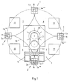
- the device for processing parts to be assembled from individual parts for a motor vehicle body has accordingly Fig. 1 a transport and positioning device 1 with several arranged around this transport and positioning device 1 around Processing stations 2, 3, 4, 5 on. Between the processing stations 2, 3, 4, 5 there are free spaces 6, 7, 8, 9, which can be used for various purposes, in particular for the placement of processing robots, tool trays, etc. The device can also be placed so that in the Free spaces 6, 7, 8, 9 are the supporting pillars of a production hall. So you can achieve an optimal adaptation to the local conditions. In the embodiment of Fig. 1 are the free spaces 6, 7 used for the placement of only schematically illustrated as boxes processing robots 10, 11, 12, 13.
- the transport and positioning device 1 has an exchangeable component holder 14, for example, a known clamping frame for the not shown, to be machined component.
- This component holder 14 is moved by the transport and positioning device 1 on a cycloidal cam track 15 with vertices 16, 17, 18, 19 to the processing stations 2, 3, 4, 5.
- the apexes 16, 17, 18, 19 of the component holder 14 and thus also the held component is held in a suitable for processing by at least one of the adjacent processing robot 10, 11, 12, 13 position.
- both the processing robot 10 and the processing robot 13 on the component perform a processing.
- the special curved path 15 creates the prerequisite that the device with the transport and positioning device 1 and the processing robots 10, 11, 12, 13 very compact builds, so has the smallest possible space requirement.
- a pivot arm 23 is mounted eccentrically to the rotor axis 22 about an axis parallel to the rotor axis 22 axis 24 rotatably.
- the swing arm 23 is drivingly coupled to the rotor 22 via a gear train in such a manner that the directions of rotation of the rotor 22 and swing arm 23 are opposite.
- an externally toothed ring gear rotatably held, which is in engagement with the rotatably supported by the rotor 22 and mounted therewith intermediate gear.
- the intermediate gear meshes with a driven gear, which is rotatably mounted at the free end of the rotor 22 and is rotatably connected to a drive shaft of the pivot arm 23.
- the rotation angle of the rotor 21 is the angle of rotation of the rotor 21 which the rotor 21 travels in order to move the pivot arm 23 or the component holder 14 by one clock angle, ie from one processing station to the next.
- the pivot arm 23 carries at its free end interchangeable the component holder 14, in particular a clamping frame, with which the component to be machined can be kept in a precisely predetermined machining position.
- a centering unit 2a, 3a, 4a, 5a may be provided in the processing stations 2, 3, 4, 5, consisting of a vertically mounted support wheel 2a * on the pivot arm 23 or component holder 14 and a stationary slide guide 2a **, 3a **, 4a **, 5a **, into which the support wheel 2a * enters during the substantially radial movement of the component holder 14.
- a rotary distributor 26 for the supply of energy and control commands is arranged, which is connected to a stationary connection point, e.g. connected to the hall ceiling.
- a cruciform memory 30 with the four vertices 16, 17, 18, 19 for a plurality of different types of component holder 32, 33 with carriers 35, 36, 37 held. Either the memory 30 is common to all carriers 35, 36, 37 or else the carriers 35, 36, 37 are individually lowerable.
- Each carrier 35, 36, 37 is equipped with a gripper 35 *, 36 *, 37 *, with which a component holder 32, 33 can be kept fixed in a favorable change position.
- a component holder change takes place in the following manner:
- the carrier 35 is empty.
- the no longer required component holder 14 is already under the carrier 35.
- This is lowered and detected with its gripper 35 * the component holder 14.
- the swivel arm 23 is brought into the processing station 5 by turning the transport and positioning device 1.
- the carrier 37 With the carrier 37, the component holder 33 is lowered from its upper parking position to its lower change position, where it is coupled to the pivot arm 23 and released by the gripper 37 *.
- the memory 30 can be equipped with even more different device holders without major device complexity by these are mounted with their carriers one behind the other radially displaceable on Speicher'30. The required component holder can then be brought by radial displacement in the favorable for the change position.
Landscapes
- Engineering & Computer Science (AREA)
- Mechanical Engineering (AREA)
- Physics & Mathematics (AREA)
- Optics & Photonics (AREA)
- Robotics (AREA)
- Chemical & Material Sciences (AREA)
- Combustion & Propulsion (AREA)
- Transportation (AREA)
- Manufacturing & Machinery (AREA)
- Automatic Assembly (AREA)
- Automobile Manufacture Line, Endless Track Vehicle, Trailer (AREA)
- Multi-Process Working Machines And Systems (AREA)
- Jigs For Machine Tools (AREA)
- Feeding Of Workpieces (AREA)
- Air-Conditioning For Vehicles (AREA)
- Control Of Electric Motors In General (AREA)
- Manipulator (AREA)
Abstract
Description
Die Erfindung betrifft eine Vorrichtung zum Bearbeiten von aus mehreren Einzelteilen zusammenzusetzenden Bauteilen für eine Kraftfahrzeugkarosserie mit einem Transport- und Positioniergerät für ein Bauteil und mehreren um dieses Transport- und Positioniergerät herum angeordneten Bearbeitungsstationen, denen das von einem auswechselbaren Bauteilhalter des Transport- und Positioniergerätes in bearbeitungsgerechter Lage gehaltene Bauteil zuführbar ist, indem der Bauteilhalter auf einer geschlossenen Umlaufbahn an den Bearbeitungsstationen vorbeigeführt wird.The invention relates to a device for processing of components to be assembled from several parts for a motor vehicle body with a transport and positioning device for a component and several arranged around this transport and positioning around processing stations, which of a replaceable component holder of the transport and positioning in editing Position held component can be fed by the component holder is guided past in a closed orbit at the processing stations.
Eine solche Vorrichtung wird z.B. im Document
Bei einer aus der Praxis wohlbekannten Vorrichtung der eingangs genannten Art ist das Transport- und Positioniergerät als Drehtisch mit mindestens einem darauf an seinem Umfang stationär angeordneten Bauteilhalter ausgebildet. Bei Drehung des Drehtisches wird der Bauteilhalter auf einem Kreis zu den außerhalb dieses Kreises angeordneten Bearbeitungsstationen bewegt. Der Wechsel eines Bauteilhalters ist aufwendig. Mittels einer Wechselvorrichtung muss der auszuwechselnde Bauteilhalter zunächst vom Drehtisch abgenommen und außerhalb der Vorrichtung abgelegt werden. Der neue Bauteilhalter wird an einem Ablageplatz aufgenommen und mit der Wechselvorrichtung zum Drehtisch transportiert. Darüber hinaus erfordert eine solche Vorrichtung viel Platz und ist an vorgegebene Räumlichkeiten kaum anpassbar.In a well-known from the practice device of the type mentioned in the transport and positioning is designed as a turntable with at least one stationary on its periphery arranged component holder. Upon rotation of the turntable, the component holder is moved on a circle to the processing stations located outside this circle. The change of a component holder is expensive. By means of a changing device, the component holder to be replaced must first be removed from the turntable and stored outside the device. The new component holder is picked up at a storage location and transported with the changing device to the turntable. In addition, such a device requires a lot of space and is hardly adaptable to given premises.
Der Erfindung liegt die Aufgabe zugrunde, eine Vorrichtung zum Bearbeiten von aus mehreren Einzelteilen zusammenzusetzenden Bauteilen für eine Kraftfahrzeugkarosserie der eingangs genannten Art zu schaffen, die bei Platz sparender Bauweise einen einfachen und schnellen Wechsel der Bauteilhalter ermöglicht.The invention has for its object to provide a device for editing composed of several parts components for a motor vehicle body of the type mentioned above, which allows a simple and quick change of the component holder in space-saving design.
Diese Aufgabe wird bei der Vorrichtung der eingangs genannten Art dadurch gelöst, dass oberhalb des Transport- und Positioniergerätes ein Speicher angeordnet ist, der die verschiedenartigen Bauteilhalter an ausgezeichneten Positionen der Umlaufbahn bereithält, wo ein vom Transport- und Positioniergerät getragener Bauteilhalter gegen einen vom Speicher getragenen andersartigen Bauteilhalter austauschbar ist.This object is achieved in the device of the type mentioned above in that above the transport and positioning a memory is arranged, which holds the various types of component holder in excellent positions of the orbit, where a supported by the transport and positioning device holder against a carried by the memory different component holder is interchangeable.
Die besondere Zuordnung der Bauteilhalter an bestimmten Positionen über dem Transport- und Positioniergerät ist Platz sparend und ermöglicht einen schnellen und einfachen Wechsel der Bauteilhalter. Das Umfeld des Transport- und Positioniergerätes steht für die Plazierung anderer Geräte, wie Bearbeitungsroboter, Flurtransportfahrzeuge, Ablagen etc. voll zur freien Verfügung. Die Bereitstellung verschiedenartiger Bauteilhalter macht es möglich, auf derselben Fertigungsanlage unterschiedliche Bauteile auch für verschiedene Fahrzeugmodelle zu fertigen. Die erfindungsgemäße Fertigungsanlage zeichnet sich deshalb auch durch eine hohe Flexibilität und kurze Umrüstzeiten aus.The special assignment of the component holder at certain positions on the transport and positioning is space-saving and allows a quick and easy change of the component holder. The environment of the transport and positioning device is fully available for the placement of other devices, such as processing robots, floor transport vehicles, shelves, etc. The provision of various component holder makes it possible to manufacture different components on the same production line for different vehicle models. The production plant according to the invention is therefore also distinguished by high flexibility and short changeover times.
Besonders günstig sind diese Verhältnisse bei einer Ausgestaltung der Erfindung, die dadurch gekennzeichnet ist, dass die geschlossene Umlaufbahn mindestens zwei Scheitelpunkte aufweist, in deren Bereich die Bearbeitungsstationen liegen, dass zwischen benachbarten Scheitelpunkten vom Bauteilhalter bei seiner Bewegung längs der geschlossenen Umlaufbahn nicht überstrichene Freiräume vor allem für die Aufstellung von Bearbeitungsrobotern verbleiben und dass der Speicher die Bauteilhalter in Bereich der Scheitelpunkte bereit hält. Die Kurvenbahn kann eine Ellipse oder Zykloide, insbesondere eine Hypozykloide oder eine Astroide sein. Bei dieser Ausgestaltung der Erfindung sind die ausgezeichneten Punkte der Kurvenbahn, an denen die Bauteilhalter vom Speicher bereitgehalten werden, die Scheitelpunkte.These conditions are particularly favorable in an embodiment of the invention, which is characterized in that the closed orbit has at least two vertices, in the area of the processing stations that between adjacent vertices of the component holder in its movement along the closed orbit not swept spaces above all remain for the placement of processing robots and that the memory holds the component holder in the area of the vertices ready. The curved path may be an ellipse or cycloid, in particular a hypocycloid or an astroide. In this embodiment of the invention, the excellent points of the curved path at which the component holder are held by the memory, the vertices.
Solche Bahnkurven lassen sich getriebetechnisch z.B. dadurch realisieren, dass das Transport- und Positioniergerät aus einem Rotor und einem darauf exzentrisch gelagerten, und entgegengesetzt zum Rotor um eine zur Rotorachse parallele Achse angetriebenen, den Bauteilhalter tragenden Schwenkarm besteht, wobei die Drehbewegungen von Rotor und Schwenkarm derart aufeinander abgestimmt sind, dass der Bauteilhalter die geschlossene Kurvenbahn mit den Scheitelpunkten beschreibt.Such trajectories can be geared, e.g. realize that the transport and positioning of a rotor and an eccentrically mounted thereon, and opposite to the rotor about an axis parallel to the rotor axis driven, the component holder supporting pivot arm, wherein the rotational movements of rotor and arm are so matched to each other that the Component holder describes the closed curved path with the vertices.
Vorzugsweise sind die vom Speicher bereit gehaltenen Bauteilhalter an einer gemeinsamen Hubvorrichtung oder individuell absenkbaren Trägern gehalten. So können die Bauteilhalter auf eine ihren Wechsel erleichternde Höhe abgesenkt werden. Bei dem Wechsel könnten auch die mit entsprechenden Greifern auszurüstenden Bearbeitungsroboter eingesetzt werden.Preferably, the component holder held ready by the memory are held on a common lifting device or individually lowerable carriers. Thus, the component holder can be lowered to a facilitating their change height. With the change could also with appropriate grippers to be equipped processing robot can be used.
Um möglichst viele verschiedenartige Bauteile bearbeiten zu können, können mehrere verschiedenartige Bauteilhalter hintereinander radial verschiebbar am Speicher gelagert sein. Der gerade benötigte Bauteilhalter lässt sich dann leicht in die optimale Wechselposition bringen.In order to be able to process as many different components as possible, several different types of component holders can be mounted on the memory one behind the other so as to be radially displaceable. The currently required component holder can then be easily brought into the optimum change position.
Die Zufuhr von Energie und Steuerbefehlen zu dem Transport- und Positioniergerät erfolgt vorzugsweise von oberhalb des Transport- und Positioniergerätes über einen auf dem Schwenkarm in dessen Drehachse angeordneten Drehverteiler. Für die Zufuhrleitungen von Energie und Steuerbefehlen kann über dem Drehverteiler nach Art einer Pleuelstange ein Leitungsbaum mit einer zentral in der Achse des Rotors angeordneten Quelle verbunden sein.The supply of energy and control commands to the transport and positioning device preferably takes place from above the transport and positioning device via a rotary distributor arranged on the pivoting arm in its axis of rotation. For the supply lines of energy and control commands, a line tree can be connected to a centrally arranged in the axis of the rotor source via the rotary distributor in the manner of a connecting rod.
Im Folgenden wird die Erfindung anhand einer ein Ausführungsbeispiel schematisch darstellenden Zeichnung näher erläutert. Im Einzelnen zeigen:
- Fig. 1
- eine Vorrichtung zum Bearbeiten von Bauteilen mit einem Transport- und Positioniergerät und mehreren Bearbeitungsstationen sowie mehreren Freiräumen für Bearbeitungsroboter in Draufsicht und
- Fig. 2
- die Vorrichtung gemäß
Fig. 1 in Seitenansicht.
- Fig. 1
- a device for processing of components with a transport and positioning and multiple processing stations and several free spaces for processing robot in plan view and
- Fig. 2
- the device according to
Fig. 1 in side view.
Die Vorrichtung zum Bearbeiten von aus Einzelteilen zusammenzusetzenden Bauteilen für eine Kraftfahrzeugkarosserie weist entsprechend
Das Transport- und Positioniergerät 1 weist einen auswechselbaren Bauteilhalter 14, z.B. einen bekannten Spannrahmen für das nicht dargestellte, zu bearbeitende Bauteil auf. Dieser Bauteilhalter 14 wird durch das Transport- und Positioniergerät 1 auf einer zykloiden Kurvenbahn 15 mit Scheitelpunkten 16, 17, 18, 19 zu den Bearbeitungsstationen 2, 3, 4, 5 bewegt. In den Scheitelpunkten 16, 17, 18, 19 wird der Bauteilhalter 14 und damit auch das gehaltene Bauteil in einer für die Bearbeitung durch mindestens einen der benachbarten Bearbeitungsroboter 10, 11, 12, 13 passenden Lage gehalten. In der in
Die beschriebene zykloide Kurvenbahn 15 mit vier Scheitelpunkten 16, 17, 18, 19 gemäß
Winkelsumme - Taktwinkel = Eigendrehwinkel des Rotors 21, wobei die Winkelsumme = 360° beträgt, der Taktwinkel der Winkel zwischen den benachbarten Scheitelpunkten 16, 17, 18, 19 /Bearbeitungsstationen = Winkel der Eigenrotation des Schwenkarms 23 bzw. des Bauteilhalters 14 zwischen den benachbarten Bearbeitungsstationen ist und Eigendrehwinkel des Rotors 21 der Drehwinkel des Rotors 21 ist, den der Rotor 21 zurücklegt, um den Schwenkarm 23 bzw. den Bauteilhalter 14 um einen Taktwinkel, d.h. von einer Bearbeitungsstation zur nächsten weiterzubewegen.The described cycloidal
Angle sum - clock angle = rotation angle of the
Der Schwenkarm 23 trägt an seinem freien Ende auswechselbar den Bauteilhalter 14, insbesondere einen Spannrahmen, mit dem das zu bearbeitende Bauteil in einer exakt vorgegebenen bearbeitungsgerechten Lage gehalten werden kann. Zur Unterstützung der Positionierung in dieser Lage kann in den Bearbeitungsstationen 2, 3, 4, 5 jeweils eine Zentriereinheit 2a, 3a, 4a, 5a vorgesehen sein, die aus einem vertikal gelagerten Stützrad 2a* am Schwenkarm 23 oder Bauteilhalter 14 und einer stationären Kulissenführung 2a**, 3a**, 4a**, 5a** besteht, in die das Stützrad 2a* bei der im Wesentlichen radialen Bewegung des Bauteilhalters 14 einläuft.The
Auf dem Schwenkarm 23 ist in dessen Drehachse 24 ein Drehverteiler 26 für die Zufuhr von Energie und Steuerbefehlen angeordnet, der mit einem ortsfesten Anschlusspunkt z.B. an der Hallendecke verbunden ist.On the
An der Hallendecke ist ein sternförmiger, im Ausführungsbeispiel ein kreuzförmiger Speicher 30 mit den vier Scheitelpunkten 16, 17, 18, 19 für mehrere verschiedenartige Bauteilhalter 32, 33 mit Trägern 35, 36, 37 gehalten. Entweder ist der Speicher 30 mit allen Trägern 35, 36, 37 gemeinsam oder aber die Träger 35, 36, 37 sind individuell absenkbar. Jeder Träger 35, 36, 37 ist mit einem Greifer 35*, 36*, 37* ausgerüstet, mit dem ein Bauteilhalter 32, 33 in einer günstigen Wechselposition fixiert gehalten werden kann.At the hall ceiling is a star-shaped, in the embodiment, a
Ein Bauteilhalterwechsel erfolgt auf folgende Art und Weise:
Im Ausführungsbeispiel ist der Träger 35 leer. Der nicht mehr benötigte Bauteilhalter 14 befindet sich bereits unter dem Träger 35. Dieser wird abgesenkt und erfasst mit seinem Greifer 35* den Bauteilhalter 14. Nachdem letzter vom Schwenkarm 23 abgekuppelt ist, wird er durch den Träger 35 in seine obere Parkposition gehoben. Um den Schwenkarm 23 mit einem neuen Bauteilhalter z.B. 33 zu bestücken, wird durch Verdrehen des Transport- und Positioniergerätes 1 der Schwenkarm 23 in die Bearbeitungsstation 5 gebracht. Mit dem Träger 37 wird der Bauteilhalter 33 aus seiner oberen Parkposition in seine untere Wechselposition abgesenkt, wo er an den Schwenkarm 23 angekuppelt und vom Greifer 37* freigegeben wird.A component holder change takes place in the following manner:
In the embodiment, the
Der Speicher 30 lässt sich ohne größeren vorrichtungstechnischen Aufwand mit noch mehr verschiedenartigen Bauteilhaltern bestücken, indem diese mit ihren Trägern hintereinander radial verschiebbar am Speicher'30 gelagert sind. Der benötigte Bauteilhalter kann dann durch radiales Verschieben in die für den Wechsel günstige Position gebracht werden.The
Claims (5)
- A device for machining components made up of a plurality of individual parts for a motor vehicle body comprising a transport and positioning unit (1) for a component and a plurality of machining stations (2, 3, 4, 5) arranged around said transport and positioning unit (1), to which the component held by an exchangeable component holder (14) of the transport and positioning unit (1) may be fed in a position ready for machining, by the component holder (14) being guided past the machining stations (2, 3, 4, 5) on a closed circulating path (15), characterised in that above the transport and positioning unit (1) a store (30) is arranged which holds in readiness different types of component holder (14, 32, 33) at specific positions on the circulating path (15), where a component holder (14) supported by the transport and positioning unit (1) may be exchanged for a different type of component holder (32, 33) carried by the store (30).
- The device according to Claim 1, characterised in that the closed circulating path comprises at least two apexes (16, 17, 18, 19), the machining stations (2, 3, 4, 5) being located in the region thereof, in that free spaces (6, 7, 8, 9) remain between adjacent apexes (16, 17, 18, 19) which are not passed over by the component holder (14) during its movement along the closed circulating path (15), and in that the store (30) holds in readiness the component holders (32, 33) in the region of the apexes (16, 17, 18, 19).
- The device according to Claim 1 or 2, characterised in that the transport and positioning unit (1) consists of a rotor (21) and a pivoting arm (23) supporting the component holder (14) and mounted eccentrically thereon and driven in opposition to the rotor (21) about an axis (24) parallel to the rotor axis (22), the rotational movements of the rotor (21) and the pivoting arm (23) being synchronised such that the component holder (14) describes the closed curved path (15) comprising the apexes (16, 17, 18, 19).
- The device according to one of Claims 1 to 3, characterised in that the component holders (32, 33) held in readiness by the store are held via supports on a common lifting device or via individually lowerable supports (36, 37).
- The device according to one of Claims 1 to 4, characterised in that a plurality of component holders (32, 33) are radially displaceably mounted on the store (30) one behind the other.
Applications Claiming Priority (2)
| Application Number | Priority Date | Filing Date | Title |
|---|---|---|---|
| DE102006020922A DE102006020922B4 (en) | 2006-05-05 | 2006-05-05 | Device for processing components of a motor vehicle body |
| PCT/EP2007/053881 WO2007128667A1 (en) | 2006-05-05 | 2007-04-20 | Device for machining components, in particular of a vehicle body |
Publications (2)
| Publication Number | Publication Date |
|---|---|
| EP2015981A1 EP2015981A1 (en) | 2009-01-21 |
| EP2015981B1 true EP2015981B1 (en) | 2009-11-11 |
Family
ID=38236409
Family Applications (1)
| Application Number | Title | Priority Date | Filing Date |
|---|---|---|---|
| EP07728340A Not-in-force EP2015981B1 (en) | 2006-05-05 | 2007-04-20 | Device for machining components, in particular of a vehicle body |
Country Status (9)
| Country | Link |
|---|---|
| US (1) | US8127415B2 (en) |
| EP (1) | EP2015981B1 (en) |
| KR (1) | KR20090010183A (en) |
| CN (1) | CN101437718B (en) |
| AT (1) | ATE448132T1 (en) |
| BR (1) | BRPI0711087A2 (en) |
| DE (2) | DE102006020922B4 (en) |
| ES (1) | ES2336274T3 (en) |
| WO (1) | WO2007128667A1 (en) |
Families Citing this family (9)
| Publication number | Priority date | Publication date | Assignee | Title |
|---|---|---|---|---|
| DE102006020924B4 (en) * | 2006-05-05 | 2009-03-19 | Thyssenkrupp Drauz Nothelfer Gmbh | Device for processing components, in particular a motor vehicle body |
| JP5454491B2 (en) * | 2011-02-25 | 2014-03-26 | 株式会社安川電機 | Work system |
| ITTO20110848A1 (en) * | 2011-09-23 | 2013-03-24 | Fond Istituto Italiano Di Tecnologia | ELASTIC ROTARY ACTUATOR. |
| US9272372B2 (en) * | 2013-11-14 | 2016-03-01 | 1202858 Alberta Ltd. | Welding spinners, and related methods and devices |
| DE202015103526U1 (en) * | 2015-07-03 | 2016-10-13 | Kuka Systems Gmbh | magazine |
| CN107322230A (en) * | 2017-08-22 | 2017-11-07 | 凯里市浪金科技有限责任公司 | A kind of fixing device of welding box body |
| CN107498308B (en) * | 2017-08-26 | 2024-06-04 | 芜湖隆深机器人有限公司 | Automatic production equipment for household appliance bottom shell |
| CN112338485B (en) * | 2020-10-31 | 2022-06-17 | 广州市燊雅精密科技有限公司 | Quick accurate automatic assembly machine |
| CN114834892B (en) * | 2022-05-30 | 2024-07-19 | 珠海华冠科技股份有限公司 | Battery cell conveying mechanism |
Family Cites Families (13)
| Publication number | Priority date | Publication date | Assignee | Title |
|---|---|---|---|---|
| JPS62222906A (en) | 1986-03-25 | 1987-09-30 | Hitachi Electronics Eng Co Ltd | Wafer transfer mechanism |
| JPH01281891A (en) | 1988-04-30 | 1989-11-13 | Tokico Ltd | Industrial robot device |
| GB2236409B (en) * | 1989-08-31 | 1993-11-10 | Mitsubishi Electric Corp | Industrial robot apparatus |
| US6366830B2 (en) | 1995-07-10 | 2002-04-02 | Newport Corporation | Self-teaching robot arm position method to compensate for support structure component alignment offset |
| DE19533320C2 (en) * | 1995-09-08 | 1999-01-28 | Ottobeurer Facondreherei Alois | Rotary transfer machine |
| DE19713860A1 (en) | 1997-04-04 | 1998-10-08 | Kuka Schweissanlagen Gmbh | Method and device for manufacturing complex workpieces |
| DE29817895U1 (en) * | 1998-10-07 | 2000-02-10 | KUKA Schweissanlagen GmbH, 86165 Augsburg | Workstation for integration into a production line equipped with industrial robots |
| DE19914125A1 (en) * | 1999-03-27 | 2000-09-28 | Volkswagen Ag | Method for manufacturing vehicles and vehicle parts in a production line has interchangeable tools and holder to work on different vehicle models in same finishing station without stopping production line |
| FR2795012B1 (en) * | 1999-06-18 | 2001-10-12 | Faciliter Les Operations Mecan | DEVICE FOR TRANSFERRING WORKPIECES |
| DE10153807A1 (en) | 2001-11-05 | 2003-05-28 | Emag Maschfab Gmbh | machine tool |
| DE20211755U1 (en) | 2002-07-30 | 2003-12-18 | Kuka Schweissanlagen Gmbh | processing plant |
| DE102005057602A1 (en) * | 2005-12-02 | 2007-06-14 | Volkswagen Ag | Processing station and method for the production of bodies |
| DE102006020924B4 (en) * | 2006-05-05 | 2009-03-19 | Thyssenkrupp Drauz Nothelfer Gmbh | Device for processing components, in particular a motor vehicle body |
-
2006
- 2006-05-05 DE DE102006020922A patent/DE102006020922B4/en not_active Expired - Fee Related
-
2007
- 2007-04-20 AT AT07728340T patent/ATE448132T1/en active
- 2007-04-20 BR BRPI0711087-1A patent/BRPI0711087A2/en not_active IP Right Cessation
- 2007-04-20 US US12/298,865 patent/US8127415B2/en not_active Expired - Fee Related
- 2007-04-20 CN CN2007800160988A patent/CN101437718B/en not_active Expired - Fee Related
- 2007-04-20 EP EP07728340A patent/EP2015981B1/en not_active Not-in-force
- 2007-04-20 KR KR1020087027069A patent/KR20090010183A/en not_active Application Discontinuation
- 2007-04-20 ES ES07728340T patent/ES2336274T3/en active Active
- 2007-04-20 DE DE502007001983T patent/DE502007001983D1/en active Active
- 2007-04-20 WO PCT/EP2007/053881 patent/WO2007128667A1/en active Application Filing
Also Published As
| Publication number | Publication date |
|---|---|
| US8127415B2 (en) | 2012-03-06 |
| ES2336274T3 (en) | 2010-04-09 |
| BRPI0711087A2 (en) | 2011-08-23 |
| ATE448132T1 (en) | 2009-11-15 |
| US20090276999A1 (en) | 2009-11-12 |
| CN101437718A (en) | 2009-05-20 |
| CN101437718B (en) | 2010-10-20 |
| EP2015981A1 (en) | 2009-01-21 |
| DE102006020922B4 (en) | 2009-05-28 |
| WO2007128667A1 (en) | 2007-11-15 |
| DE102006020922A1 (en) | 2007-11-08 |
| DE502007001983D1 (en) | 2009-12-24 |
| KR20090010183A (en) | 2009-01-29 |
Similar Documents
| Publication | Publication Date | Title |
|---|---|---|
| EP2015981B1 (en) | Device for machining components, in particular of a vehicle body | |
| EP2015891B1 (en) | Device for machining components, in particular of a vehicle body | |
| EP1873045B1 (en) | Multi-flexible production facility for motor vehicle bodies assembled from several parts | |
| AT519480B1 (en) | Bending tool storage device | |
| DE8417022U1 (en) | Rotary table machining device | |
| EP3096921A2 (en) | Machining device for machine-assisted production and machining of dental workpieces | |
| EP0355455B1 (en) | Tool magazine for machine tools | |
| WO2019052859A1 (en) | Tool magazine and method for changing tools | |
| DE19843889B4 (en) | Punching tool storage and changing system | |
| EP1216787B1 (en) | Positioning device | |
| EP1426137A2 (en) | Machine tool | |
| DE3722180A1 (en) | Transfer machine | |
| DE69414453T2 (en) | Automatic tool changer | |
| DE102011107467A1 (en) | Rotary transfer machine | |
| DE102006020923B4 (en) | Production plant for complex components, in particular a motor vehicle body | |
| EP1430992A1 (en) | Device for transferring flat workpieces with a linearly movable rotating arm | |
| DE102007056690B4 (en) | Plant for the production of a lightweight structure | |
| EP0137117B1 (en) | Tool-changing unit having a presentation device for tool-heads | |
| DE4421624C2 (en) | Tool changing device for a universal machine tool | |
| DE2405954C3 (en) | Device for turning with simultaneous transverse conveying of prismatic or nearly prismatic rolling stock | |
| DE3001396A1 (en) | Machine tool with indexing tool head - has transfer unit between head and endless conveyor for tool carriers in tool magazine carriage | |
| DE10343378B4 (en) | Device for processing workpieces at a number of workstations | |
| DE3829681A1 (en) | Method and apparatus for automatically transferring shaped parts, in particular stones in the refractory industry | |
| DE19953949A1 (en) | Device for loading parts carriers for microsystems | |
| DE3335043A1 (en) | Manipulating device |
Legal Events
| Date | Code | Title | Description |
|---|---|---|---|
| PUAI | Public reference made under article 153(3) epc to a published international application that has entered the european phase |
Free format text: ORIGINAL CODE: 0009012 |
|
| 17P | Request for examination filed |
Effective date: 20081028 |
|
| AK | Designated contracting states |
Kind code of ref document: A1 Designated state(s): AT BE BG CH CY CZ DE DK EE ES FI FR GB GR HU IE IS IT LI LT LU LV MC MT NL PL PT RO SE SI SK TR |
|
| AX | Request for extension of the european patent |
Extension state: AL BA HR MK RS |
|
| GRAP | Despatch of communication of intention to grant a patent |
Free format text: ORIGINAL CODE: EPIDOSNIGR1 |
|
| GRAS | Grant fee paid |
Free format text: ORIGINAL CODE: EPIDOSNIGR3 |
|
| GRAA | (expected) grant |
Free format text: ORIGINAL CODE: 0009210 |
|
| AK | Designated contracting states |
Kind code of ref document: B1 Designated state(s): AT BE BG CH CY CZ DE DK EE ES FI FR GB GR HU IE IS IT LI LT LU LV MC MT NL PL PT RO SE SI SK TR |
|
| REG | Reference to a national code |
Ref country code: GB Ref legal event code: FG4D Free format text: NOT ENGLISH |
|
| REG | Reference to a national code |
Ref country code: CH Ref legal event code: EP |
|
| REG | Reference to a national code |
Ref country code: IE Ref legal event code: FG4D |
|
| REF | Corresponds to: |
Ref document number: 502007001983 Country of ref document: DE Date of ref document: 20091224 Kind code of ref document: P |
|
| REG | Reference to a national code |
Ref country code: SE Ref legal event code: TRGR |
|
| NLV1 | Nl: lapsed or annulled due to failure to fulfill the requirements of art. 29p and 29m of the patents act | ||
| REG | Reference to a national code |
Ref country code: ES Ref legal event code: FG2A Ref document number: 2336274 Country of ref document: ES Kind code of ref document: T3 |
|
| LTIE | Lt: invalidation of european patent or patent extension |
Effective date: 20091111 |
|
| PG25 | Lapsed in a contracting state [announced via postgrant information from national office to epo] |
Ref country code: FI Free format text: LAPSE BECAUSE OF FAILURE TO SUBMIT A TRANSLATION OF THE DESCRIPTION OR TO PAY THE FEE WITHIN THE PRESCRIBED TIME-LIMIT Effective date: 20091111 Ref country code: LT Free format text: LAPSE BECAUSE OF FAILURE TO SUBMIT A TRANSLATION OF THE DESCRIPTION OR TO PAY THE FEE WITHIN THE PRESCRIBED TIME-LIMIT Effective date: 20091111 Ref country code: PT Free format text: LAPSE BECAUSE OF FAILURE TO SUBMIT A TRANSLATION OF THE DESCRIPTION OR TO PAY THE FEE WITHIN THE PRESCRIBED TIME-LIMIT Effective date: 20100311 Ref country code: IS Free format text: LAPSE BECAUSE OF FAILURE TO SUBMIT A TRANSLATION OF THE DESCRIPTION OR TO PAY THE FEE WITHIN THE PRESCRIBED TIME-LIMIT Effective date: 20100311 |
|
| PG25 | Lapsed in a contracting state [announced via postgrant information from national office to epo] |
Ref country code: LV Free format text: LAPSE BECAUSE OF FAILURE TO SUBMIT A TRANSLATION OF THE DESCRIPTION OR TO PAY THE FEE WITHIN THE PRESCRIBED TIME-LIMIT Effective date: 20091111 Ref country code: PL Free format text: LAPSE BECAUSE OF FAILURE TO SUBMIT A TRANSLATION OF THE DESCRIPTION OR TO PAY THE FEE WITHIN THE PRESCRIBED TIME-LIMIT Effective date: 20091111 Ref country code: SI Free format text: LAPSE BECAUSE OF FAILURE TO SUBMIT A TRANSLATION OF THE DESCRIPTION OR TO PAY THE FEE WITHIN THE PRESCRIBED TIME-LIMIT Effective date: 20091111 Ref country code: CY Free format text: LAPSE BECAUSE OF FAILURE TO SUBMIT A TRANSLATION OF THE DESCRIPTION OR TO PAY THE FEE WITHIN THE PRESCRIBED TIME-LIMIT Effective date: 20091111 |
|
| REG | Reference to a national code |
Ref country code: IE Ref legal event code: FD4D |
|
| PG25 | Lapsed in a contracting state [announced via postgrant information from national office to epo] |
Ref country code: RO Free format text: LAPSE BECAUSE OF FAILURE TO SUBMIT A TRANSLATION OF THE DESCRIPTION OR TO PAY THE FEE WITHIN THE PRESCRIBED TIME-LIMIT Effective date: 20091111 Ref country code: EE Free format text: LAPSE BECAUSE OF FAILURE TO SUBMIT A TRANSLATION OF THE DESCRIPTION OR TO PAY THE FEE WITHIN THE PRESCRIBED TIME-LIMIT Effective date: 20091111 Ref country code: IE Free format text: LAPSE BECAUSE OF FAILURE TO SUBMIT A TRANSLATION OF THE DESCRIPTION OR TO PAY THE FEE WITHIN THE PRESCRIBED TIME-LIMIT Effective date: 20091111 Ref country code: DK Free format text: LAPSE BECAUSE OF FAILURE TO SUBMIT A TRANSLATION OF THE DESCRIPTION OR TO PAY THE FEE WITHIN THE PRESCRIBED TIME-LIMIT Effective date: 20091111 Ref country code: BG Free format text: LAPSE BECAUSE OF FAILURE TO SUBMIT A TRANSLATION OF THE DESCRIPTION OR TO PAY THE FEE WITHIN THE PRESCRIBED TIME-LIMIT Effective date: 20100211 |
|
| PG25 | Lapsed in a contracting state [announced via postgrant information from national office to epo] |
Ref country code: CZ Free format text: LAPSE BECAUSE OF FAILURE TO SUBMIT A TRANSLATION OF THE DESCRIPTION OR TO PAY THE FEE WITHIN THE PRESCRIBED TIME-LIMIT Effective date: 20091111 Ref country code: SK Free format text: LAPSE BECAUSE OF FAILURE TO SUBMIT A TRANSLATION OF THE DESCRIPTION OR TO PAY THE FEE WITHIN THE PRESCRIBED TIME-LIMIT Effective date: 20091111 |
|
| PLBE | No opposition filed within time limit |
Free format text: ORIGINAL CODE: 0009261 |
|
| STAA | Information on the status of an ep patent application or granted ep patent |
Free format text: STATUS: NO OPPOSITION FILED WITHIN TIME LIMIT |
|
| 26N | No opposition filed |
Effective date: 20100812 |
|
| PG25 | Lapsed in a contracting state [announced via postgrant information from national office to epo] |
Ref country code: GR Free format text: LAPSE BECAUSE OF FAILURE TO SUBMIT A TRANSLATION OF THE DESCRIPTION OR TO PAY THE FEE WITHIN THE PRESCRIBED TIME-LIMIT Effective date: 20100212 |
|
| PG25 | Lapsed in a contracting state [announced via postgrant information from national office to epo] |
Ref country code: MC Free format text: LAPSE BECAUSE OF NON-PAYMENT OF DUE FEES Effective date: 20100430 |
|
| PG25 | Lapsed in a contracting state [announced via postgrant information from national office to epo] |
Ref country code: IT Free format text: LAPSE BECAUSE OF NON-PAYMENT OF DUE FEES Effective date: 20100420 |
|
| PG25 | Lapsed in a contracting state [announced via postgrant information from national office to epo] |
Ref country code: MT Free format text: LAPSE BECAUSE OF FAILURE TO SUBMIT A TRANSLATION OF THE DESCRIPTION OR TO PAY THE FEE WITHIN THE PRESCRIBED TIME-LIMIT Effective date: 20091111 |
|
| REG | Reference to a national code |
Ref country code: CH Ref legal event code: PL |
|
| PG25 | Lapsed in a contracting state [announced via postgrant information from national office to epo] |
Ref country code: LI Free format text: LAPSE BECAUSE OF NON-PAYMENT OF DUE FEES Effective date: 20110430 Ref country code: CH Free format text: LAPSE BECAUSE OF NON-PAYMENT OF DUE FEES Effective date: 20110430 |
|
| PG25 | Lapsed in a contracting state [announced via postgrant information from national office to epo] |
Ref country code: HU Free format text: LAPSE BECAUSE OF FAILURE TO SUBMIT A TRANSLATION OF THE DESCRIPTION OR TO PAY THE FEE WITHIN THE PRESCRIBED TIME-LIMIT Effective date: 20100512 Ref country code: NL Free format text: LAPSE BECAUSE OF FAILURE TO SUBMIT A TRANSLATION OF THE DESCRIPTION OR TO PAY THE FEE WITHIN THE PRESCRIBED TIME-LIMIT Effective date: 20091111 Ref country code: LU Free format text: LAPSE BECAUSE OF NON-PAYMENT OF DUE FEES Effective date: 20100420 |
|
| PG25 | Lapsed in a contracting state [announced via postgrant information from national office to epo] |
Ref country code: TR Free format text: LAPSE BECAUSE OF FAILURE TO SUBMIT A TRANSLATION OF THE DESCRIPTION OR TO PAY THE FEE WITHIN THE PRESCRIBED TIME-LIMIT Effective date: 20091111 |
|
| REG | Reference to a national code |
Ref country code: AT Ref legal event code: MM01 Ref document number: 448132 Country of ref document: AT Kind code of ref document: T Effective date: 20120420 |
|
| PG25 | Lapsed in a contracting state [announced via postgrant information from national office to epo] |
Ref country code: AT Free format text: LAPSE BECAUSE OF NON-PAYMENT OF DUE FEES Effective date: 20120420 |
|
| REG | Reference to a national code |
Ref country code: FR Ref legal event code: PLFP Year of fee payment: 9 |
|
| PGFP | Annual fee paid to national office [announced via postgrant information from national office to epo] |
Ref country code: BE Payment date: 20150420 Year of fee payment: 9 Ref country code: FR Payment date: 20150421 Year of fee payment: 9 |
|
| PG25 | Lapsed in a contracting state [announced via postgrant information from national office to epo] |
Ref country code: BE Free format text: LAPSE BECAUSE OF NON-PAYMENT OF DUE FEES Effective date: 20160430 |
|
| REG | Reference to a national code |
Ref country code: FR Ref legal event code: ST Effective date: 20161230 |
|
| PG25 | Lapsed in a contracting state [announced via postgrant information from national office to epo] |
Ref country code: FR Free format text: LAPSE BECAUSE OF NON-PAYMENT OF DUE FEES Effective date: 20160502 |
|
| PGFP | Annual fee paid to national office [announced via postgrant information from national office to epo] |
Ref country code: DE Payment date: 20170419 Year of fee payment: 11 Ref country code: GB Payment date: 20170419 Year of fee payment: 11 |
|
| PGFP | Annual fee paid to national office [announced via postgrant information from national office to epo] |
Ref country code: IT Payment date: 20170424 Year of fee payment: 11 Ref country code: ES Payment date: 20170510 Year of fee payment: 11 Ref country code: SE Payment date: 20170419 Year of fee payment: 11 |
|
| REG | Reference to a national code |
Ref country code: DE Ref legal event code: R119 Ref document number: 502007001983 Country of ref document: DE |
|
| REG | Reference to a national code |
Ref country code: SE Ref legal event code: EUG |
|
| GBPC | Gb: european patent ceased through non-payment of renewal fee |
Effective date: 20180420 |
|
| PG25 | Lapsed in a contracting state [announced via postgrant information from national office to epo] |
Ref country code: DE Free format text: LAPSE BECAUSE OF NON-PAYMENT OF DUE FEES Effective date: 20181101 Ref country code: SE Free format text: LAPSE BECAUSE OF NON-PAYMENT OF DUE FEES Effective date: 20180421 |
|
| PG25 | Lapsed in a contracting state [announced via postgrant information from national office to epo] |
Ref country code: GB Free format text: LAPSE BECAUSE OF NON-PAYMENT OF DUE FEES Effective date: 20180420 |
|
| PG25 | Lapsed in a contracting state [announced via postgrant information from national office to epo] |
Ref country code: IT Free format text: LAPSE BECAUSE OF NON-PAYMENT OF DUE FEES Effective date: 20180420 |
|
| REG | Reference to a national code |
Ref country code: ES Ref legal event code: FD2A Effective date: 20190912 |
|
| PG25 | Lapsed in a contracting state [announced via postgrant information from national office to epo] |
Ref country code: ES Free format text: LAPSE BECAUSE OF NON-PAYMENT OF DUE FEES Effective date: 20180421 |