EP2015615A2 - Ferngesteuertes Beleuchtungssteuerungssystem - Google Patents
Ferngesteuertes Beleuchtungssteuerungssystem Download PDFInfo
- Publication number
- EP2015615A2 EP2015615A2 EP20080105433 EP08105433A EP2015615A2 EP 2015615 A2 EP2015615 A2 EP 2015615A2 EP 20080105433 EP20080105433 EP 20080105433 EP 08105433 A EP08105433 A EP 08105433A EP 2015615 A2 EP2015615 A2 EP 2015615A2
- Authority
- EP
- European Patent Office
- Prior art keywords
- control
- status
- devices
- electrical
- control unit
- Prior art date
- Legal status (The legal status is an assumption and is not a legal conclusion. Google has not performed a legal analysis and makes no representation as to the accuracy of the status listed.)
- Withdrawn
Links
Images




Classifications
-
- H—ELECTRICITY
- H01—ELECTRIC ELEMENTS
- H01Q—ANTENNAS, i.e. RADIO AERIALS
- H01Q7/00—Loop antennas with a substantially uniform current distribution around the loop and having a directional radiation pattern in a plane perpendicular to the plane of the loop
- H01Q7/005—Loop antennas with a substantially uniform current distribution around the loop and having a directional radiation pattern in a plane perpendicular to the plane of the loop with variable reactance for tuning the antenna
-
- H—ELECTRICITY
- H05—ELECTRIC TECHNIQUES NOT OTHERWISE PROVIDED FOR
- H05B—ELECTRIC HEATING; ELECTRIC LIGHT SOURCES NOT OTHERWISE PROVIDED FOR; CIRCUIT ARRANGEMENTS FOR ELECTRIC LIGHT SOURCES, IN GENERAL
- H05B47/00—Circuit arrangements for operating light sources in general, i.e. where the type of light source is not relevant
- H05B47/10—Controlling the light source
- H05B47/175—Controlling the light source by remote control
- H05B47/19—Controlling the light source by remote control via wireless transmission
- H05B47/195—Controlling the light source by remote control via wireless transmission the transmission using visible or infrared light
-
- H—ELECTRICITY
- H05—ELECTRIC TECHNIQUES NOT OTHERWISE PROVIDED FOR
- H05B—ELECTRIC HEATING; ELECTRIC LIGHT SOURCES NOT OTHERWISE PROVIDED FOR; CIRCUIT ARRANGEMENTS FOR ELECTRIC LIGHT SOURCES, IN GENERAL
- H05B47/00—Circuit arrangements for operating light sources in general, i.e. where the type of light source is not relevant
- H05B47/10—Controlling the light source
- H05B47/175—Controlling the light source by remote control
- H05B47/196—Controlling the light source by remote control characterised by user interface arrangements
Definitions
- the present invention relates, generally, to remote control systems, and, more particularly, to a pre-programmed radio frequency (RF) control system and method for controlling one or more lighting controls.
- RF radio frequency
- prior art systems and methods control the status of electrical devices such as electric lamps, from a remote location via communication links, including radio frequency links, power line carrier links or infrared links.
- Status information regarding the electrical devices e.g., on, off and intensity level
- At least one repeater device may also be provided to help ensure reliable communications between the master control unit and the control devices for the respective electrical devices.
- the repeater may be required when a control device is unable to receive control signals transmitted directly from the master control unit, and, typically, employs a repeater sequence for helping to ensure that each receiver receives those signals intended for it.
- the present invention is directed particularly to lighting controls, the present invention can be applied to communication signals relating to the control of status of other kinds of devices, such as, for example, fan motors and motorized window treatments.
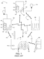
- Fig. 1 a prior art arrangement of a system 100 for remote control of electrical devices.
- the example prior art system 100 illustrated in Fig. 1 includes configurable devices that are manufactured by the assignee of the present patent application and commercially known as the RadioRA® lighting control system.
- the RadioRA® lighting control system is described in greater detail in commonly assigned U.S. Patent No. 5,905,442, issued May 18, 1999 , entitled METHOD AND APPARATUS FOR CONTROLLING AND DETERMINING THE STATUS OF ELECTRICAL DEVICES FROM REMOTE LOCATIONS, the entire disclosure of which is hereby incorporated by reference.
- the hardware devices include a master control unit 102, two control devices 104, a repeater 106, a car visor control 108 that may be mounted on an automobile's sun visor, and two electrical devices 110, e.g., lamps.
- the devices 102, 104, 106 and 108 transmit radio frequency signals 112, which can include control information and instructions regarding the respective electrical devices 110.
- each control device 104 includes a communications and control circuit 114 that comprises a radio frequency transmitter/receiver 116 and an antenna 118 for transmitting/receiving the radio frequency signals 112.
- the communications and control circuit 114 further includes a controller 120 for adjusting the status of the attached electrical device 110.
- the transmitter/receiver 116 receives the radio frequency signals via the antenna 118 and transmits a status radio frequency signal with information regarding the status of the controller 120 (which indirectly reflects the status of the connected electrical device 110).
- the controller 120 adjusts the status of the electrical device in response to the control information.
- Each control device 104 further includes button(s) 122 and dimmer control(s) 124, which are further operable to allow manual adjustment of the connected electrical device 110.
- the master control unit 102 includes at least one actuator 126, at least one status indicator 128, a transmitter/receiver 116, and an antenna 118.
- the actuators 126 enable a user to control the electrical devices 110 remotely.
- the status indicators 128 indicate the status of the electrical devices 110.
- the transmitter/receiver 116 and the antenna 118 are operable for transmitting a radio frequency signal 112 having the control information therein to control the status of the electrical devices 110, as well as for receiving status information from the control devices 104.
- the master control unit 102 can take several forms.
- the master control unit 102 can be formed as a tabletop master, which plugs into an electrical outlet and includes a conventional antenna for transmitting and receiving signals.
- the master control unit 102 mounts on a wall, and is sized such that the master control unit 102 fits within the confines of a standard electrical wall box.
- the master control unit 102 includes a plurality of controls, each associated with a particular control device or a plurality of control devices.
- the user must program the association of the electrical control devices to a particular actuator 126 on the master control unit.
- prior art master control units 102 must be programmed in order to provide functions allowing all control devices 104 to turn on or off substantially simultaneously.
- the repeater 106 may receive radio frequency signals 112 (including status information and instructions) from the master control unit 102 and, thereafter, transmit radio frequency signals 112 to the control devices 104. Further, the repeater 106 may receive radio frequency signals 112 from the control devices 104 and, thereafter, transmit them to the master control unit 102.
- the car visor control 108 provides a convenient and remotely usable interface to transmit radio frequency signals 112 to the master control unit 102, and may be disposed in a vehicle, for example, on a vehicle's interior sun visor.
- the buttons 130 are provided for remotely activating the master control unit 102.
- the car visor control 108 can be used to cause a lighting scene to turn on/off, or may be operated to turn the electrical devices 110 on/off via the master control unit 102.
- the master control unit 102 is operable to generate radio frequency signals, which are transmitted to and received by the control devices 104, such as light dimmers, and/or the repeater 106.
- the control devices 104 use the information received in the radio frequency signals 112 to control the connected electrical devices 110 to a desired intensity.
- the control devices 104 preferably transmit radio frequency signals 112 via antennas 118 to the master control unit 102 (or to the master control unit 102 via the repeater 106) in order to indicate the status of the control devices 104 (and thus, the connected electrical devices 110).
- a combination of lighting controls in different or the same rooms of a structure for example, can be instructed to turn on/off, thereby creating a lighting "scene" according to a user's desire.
- Lighting control devices 104 preferably fit into standard electrical wall boxes.
- the antenna 118 which comprises a part of each control device 104, is sized so as to fit within the standard electrical wall box or at least within the area defined by the faceplate for the opening of a standard electrical wall box.
- prior art remote control systems place a technical requirement on the user (or the installer) to set up and configure the master control unit 102, control devices 104, and repeater 106.
- a prior art remote electrical device control system is purchased and wired to an existing electrical system, a user must configure the system to enjoy the respective functionality thereof. For example, a user must activate repeater(s) 106, control devices 104 (including dimmer controls) and master control unit 102 before a prior art remote control system can be used.
- the master control unit 102 is typically programmed so that, for example, one or more master control unit 102 buttons can control a light or group of lights.
- each control device 104 must be configured to correspond with respective buttons on master control unit 102.
- Other functionality provided by prior art remote control systems that must be programmed and/or configured by a user include: assigning dimmers, switches, and sensor units to specific room buttons; setting light levels and lighting scene selection for specific room buttons; assigning dimmers, switches and sensors to scene buttons; programming a button of a master control unit 102 to turn all electrical devices on and off; copying button programming; erasing button programming; adding auxiliary repeaters; adding controls; activating switch closure interfaces; assigning dimmers, switches and/or sensor devices to input channels; and setting light levels and/or scene selection for input channels.
- prior art systems may be distributed with a hand-written programming worksheet to be used by the user to set up or change the configuration of a system.
- a user writes, in a worksheet, descriptions of associations of the respective devices, as well as the various functionality provided by respective buttons provided on the devices. Accordingly, the user refers to the hand-written worksheet in order to effect changes to the system, and/or for troubleshooting purposes.
- prior art remote control systems regards defining a unique address to prevent interference with neighboring systems.
- each neighbor may adversely affect the status of the other's electrical devices.
- a user's lights may turn on, off, dim, and brighten each time the neighbor operates his system.
- prior art remote control systems require users to define a unique "house" or system address by supplying a bit address in the range of 0-255. Once defined, a prior art remote control system can broadcast radio frequency signals with the assurance that no neighboring system will receive and respond to the transmissions.
- configuring the system with a unique house address is an additional technical burden placed on the user, and represents another shortcoming of the prior art.
- Yet another shortcoming of prior art remote control systems regards the amount and frequency of information that is transmitted from the control device 104 to the master control unit 102, especially while the user affects the status of the electrical device 110 using a dimmer.
- a user adjusts the brightness of a light via a dimmer.
- an electric light e.g., dimming the light
- information regarding the status of the light is transmitted to the master control unit 102, even if the user has not completed adjusting the brightness level of the light.
- control devices 104 comprising dimmer controls.
- dimmers are typically provided with rocker switches or other kinds of switching mechanisms.
- a rocker switch does not provide the same degree of control as a slider control. Therefore, it is considered by the inventors that an additional shortcoming of prior art remote control systems, particularly with respect to radio frequency remote controls, is that dimmers are not provided with slider controls.
- a system for remotely controlling at least two electrical devices comprises a master control unit and at least two control devices.
- the master control unit is operable to transmit signals containing control information for controlling the electrical devices.
- the at least two control devices are operable to receive the signals from the master control unit.
- Each of the control devices is respectively electrically connected to at least one of the electrical devices and is responsive to the control information for controlling the at least one of the electrical devices.
- the control information includes a unique identifier of at least one of the control devices.
- the master control unit and the control devices are pre-configured such that the master control unit is operable to transmit the signals to the control devices, and the control devices are operable to receive the signals from the master control unit and control the status of the at least one electrically connected electrical device in response to the control information containing the address of the respective control device, immediately upon installing and providing power to the system in a building structure.
- a two-way radio frequency lighting control system comprises a master control and a plurality of dimmers.
- the master control includes a plurality of manual actuators. The number of dimmers does not exceed the number of manual actuators.
- the present invention further provides a lighting control system that comprises a master control and a plurality of dimmers.
- the master control includes a plurality of master manual actuators; a master controller, operatively coupled to the master manual actuators; a plurality of master status indicators, operatively coupled to the master controller; a master radio frequency transmitter-receiver, operative coupled to the master controller; and a master antenna, operatively coupled to the master transmitter-receiver.
- Each of the plurality of dimmers includes a dimmer manual on/off actuator; a dimmer slider actuator; a dimmer controller, operatively coupled to the dimmer manual on/off actuator and to the dimmer slider actuator; a dimmer controllably conductive device, operatively coupled to the dimmer controller; a dimmer radio frequency transmitter-receiver, operatively coupled to the dimmer controller; and a dimmer antenna, operatively coupled to the dimmer radio frequency transmitter-receiver.
- the number of dimmers not exceeding the number of master manual actuators.
- the master controller and each of the plurality of dimmer controllers are programmed prior to installation in an intended end user location, such that each master manual actuators is operative to cause a change in status of one, and only one, of each of the plurality of dimmers.
- the present invention provides a dimmer control operable to adjust a status of a connected electrical lamp in response to a radio frequency control signal received from a remote control device.
- the dimmer control comprises a communication and control circuit, a manual actuator, and a slider control.
- the communication and control circuit includes at least a radio frequency transmitter/receiver and an antenna operable to receive a radio frequency signal from the remote control device that includes control information for controlling the status of the electrical lamp.
- the manual actuator is operable to change the on/off status of the electrical lamp, while the slider control is operable to change the dimming status of the electrical lamp to dim the electrical lamp.
- the communication and control circuit is operable to transmit to the remote control device status information representing the changed status of the electrical lamp, or the setting of the slider control, or both.
- the present invention further provides a method of dimming an electrical lamp electrically connected to a control device in response to a radio frequency control signal received from a remote control device.
- the method comprises the step of providing the control device with a communication and control circuit comprising at least a radio frequency transmitter/receiver and an antenna, a manual actuator operable to change the on/off status of the electrical lamp, and a slider control operable to change the dimming status of the electrical lamp.
- the communication and control circuit is operable to receive the radio frequency control signal.
- the method further comprises the steps of receiving the radio frequency control signal that includes control information for controlling the status of the electrical lamp; controlling the status of the lamp in response to the control information; dimming the electrical device as a function of the position of the slider control; and transmitting by the communication and control circuit status information representing the changed status of the electrical lamp to the remote control device.
- a method for providing a remote control system operable to control at least two electrical devices comprises the steps of: providing a master control unit operable to transmit signals containing control information for controlling the electrical devices, and providing at least two control devices.
- Each of the control devices is respectively electrically connected to at least one of the electrical devices and is responsive to the control information to control the at least one of the electrical devices.
- the control information includes a unique identifier of at least one of the control devices.
- the method further comprises the step of pre-configuring the master control unit and the control devices such that the master control unit is operable to transmit signals to the control devices, and the control devices are operable to receive the signals from the master control unit and control the status of the at least one electrically connected electrical device in response to the control information containing the address of the respective control device, immediately upon installing and providing power to the master control unit and the control devices in a building structure.
- Fig. 1 illustrates a prior art arrangement of a radio frequency system for remote control of electrical devices
- Fig. 2 shows an exemplary hardware arrangement of components and devices of an RF lighting control system according to a preferred embodiment of the present invention
- Fig. 3 shows a master control unit of the lighting control system of Fig. 2 ;
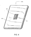
- Fig. 4 illustrates a control device of the lighting control system of Fig. 2 ;
- Fig. 5 is a simplified block diagram of a dimmer control device that may operate in the lighting control system of Fig. 2 ;
- Fig. 6 is a flow chart that represents a process associated with configuring and distributing the remote control system of the present invention.
- Fig. 7 illustrates a flow chart that includes the process associated with installing the present invention from the perspective of a retail consumer.
- the present invention is directed to a wireless radio frequency (RF) control system for controlling electrical devices, for example installed in a building structure such as a residential home, and made available in a retail market.
- RF radio frequency
- a remotely and manually controllable control device replaces a conventional mechanical electrical switch, and operates without requiring setup and/or configuration by a user thereby reducing the time and resources required for the installation of prior art remote control systems.
- FIG. 2 an example hardware arrangement of components and devices in a building installation in accordance with a preferred embodiment of the present invention is displayed, and referred to herein generally as remote control system 200.
- the system comprises, for example, one master control unit 202, five control devices 204A - 204E, one repeater 206, and two car visor controls 208A, 208B, which represent a preferred combination of devices packaged and distributed for the retail market.
- each of the control devices 204A - 204E is installed to replace a traditional mechanical switch.
- control devices 204A - 204E and the master control unit 202 are preferably pre-programmed to support the functionality described herein without requiring configuration and programming by the user.
- the master control unit 202 includes a plurality of device control buttons 302A - 302E.
- Each of the device control buttons 302A - 302E is operable to control one, and only one, of the control devices 204A - 204E.
- a first device button 302A on master control unit 202 is operable to cause unit 202 to transmit commands to which only the first control device 204A will respond.
- the second device button 302B commands the second control device 204B; the third device button 302C commands the third control device 204C; and so forth.
- the master control unit 202 transmits control information to the control devices 204A - 204E in response to an actuation of one of the device control buttons 302A - 302E.
- the control information includes a unique identifier of one of the control devices 204A - 204E. For example, if the first device control button 302A is pressed, the control information may include an address uniquely identifying the control device 204A. Note that the unique identifiers are preferably not user selectable, e.g., not DIP switches.
- Fig. 3 illustrates an example master control unit 202 in accordance with the present invention.
- the example master control unit 202 shown in Fig. 3 is of the table top variety, plugs into a standard electric outlet, and can be placed anywhere in a home, such as, for example, on a bedside table.
- the master control unit 202 can be provided in other various forms, including as a wall mounted device.
- the master control unit 202 includes the device buttons 302A - 302E, which, when pressed, operate to cause the master control unit 202 to transmit the radio frequency signal 112 and instruct the control device 204A to turn the electrical device 110 on or off.
- the master control unit 202 comprises an "all-on" button 304 (described in greater detail below), which operates to turn on a combination of the control devices 204A - 204E to various levels, thereby providing a lighting preset (or "scene”).
- the master control unit 202 further comprises an "all-off” button 305, which operates to turn off all of the control devices 204A - 204E when pressed.
- Fig. 4 illustrates an example of the control device 204A in accordance with a preferred embodiment of the present invention.
- the control device 204A is equipped with a slider control 402 and an actuator, e.g., a button 404.
- An antenna (not shown) is preferably provided inside or behind the button 404 and is used for transmitting/receiving radio frequency signals to/from the master control unit 202, either directly or indirectly via the repeater 206.
- the control device 204A is preferably arranged with a faceplate 408.
- the faceplate need not be limited to any specific form and preferably has a traditional style opening, such that the faceplate can be used for the control devices 204A - 204E as well as a standard mechanical wall switch (i.e., the wall switch that the control device is replacing).
- a traditional style opening is a rectangular opening having a minimum width of 0.401 +/- 0.005 inch, an a minimum length of 0.925 +/- 0.005 inch.
- the slider control 402 represents an improvement over prior art radio-frequency remote control systems that provide dimming functionality via a rocker switch (described above).
- the slider controls 402 are believed to be much more intuitive to use than rocker switches, and, further, enable a user to recognize at a glance the particular level set for a respective electrical device.
- Prior art rocker switches in contrast, do not provide a convenient visual indication of a dimming level as slider controls do.
- the buttons 302A - 302E on master control unit 202 preferably function as follows.
- a respective device button e.g., the device button 302A
- control information is transmitted to the respective control device (e.g., the control device 204A) to turn on the connected electrical device 210 to full power.
- the electrical device 210 turns on to the level defined by the position of the slider control 402 on the control device 204A. In this way, a user has greater control over the operation of the electrical devices 210 of the remote control system.
- the master control unit 202 and the control devices 204A - 204E are configured and programmed prior to retail distribution such that the buttons 302A - 302E on the master control unit 202 automatically correspond to the respective control devices. For example, pressing the button 302D on the master control 202 will cause the control device 204D to toggle the attached lighting load.
- a user can control an individual electrical device 210 in accordance with the teachings herein, without the need to configure the system for use.
- the user could be provided the option of overriding the pre-programmed state of the master control unit 202 and the control devices 204A - 204E by programming and configuring the system to accommodate individual preferences.
- the present invention provides a pre-configured system "out of the box", i.e., when the product is shipped.
- the system 200 immediately after installation when energized for the first time, the system 200 is operable to function such that the first button 302A on the master control unit 202 controls the first control device 204A; the second button 302B on the master control unit 202 controls the second control device 204B; and so on.
- the present invention eliminates the requirement in prior art systems that a user configure the system to assign a unique house address code (e.g., via a bit assignment ranging from 0 - 255).
- unique house codes are required to prevent the system 200 from controlling unintended devices (e.g., those located at a neighboring house).
- no programming is required by the user in order to establish a unique house code because the system is preferably shipped with preset system codes.
- the invention preferably defines a unique system address for each shipped system that is defined within the range of 0 - 2 24 .
- a user is not required to program a unique house code, because the present invention provides a large range of unique addresses such that no interference with neighboring systems is substantially ensured.
- the control devices 204A - 204E preferably are labeled when shipped with a removable label having a printed number (or other designation) that associates a specific control device with one of the buttons 302A - 302E on the master control unit 202.
- the third control device 204C may have a label with the number three (3) included on its surface. Accordingly, when the control device 204C is removed from the packaging during installation, the end user is aware that the control device 204C will be operated by pressing the third button 302C of the master control unit 202.
- buttons 404 of the control devices 204A - 204E may each be of the same color as the corresponding buttons 302A - 302E of the master control unit 202.
- the button 404 of the control device 204A and the first button 302A of the master control unit 202 may both be colored red to emphasize to the user that the first button 302A controls the first control device 204A.
- each of the buttons 302A - 302E of the master control unit 202 (and each of the buttons 404 of the control devices 204A - 204E) may be of different colors such that the buttons of the master control will be easily distinguishable and the control device that each button of the master control operates will be well known.
- buttons 302A - 302E of the master control 202 and the buttons 404 of the control devices 204A - 204E may have the colors red, blue, green, yellow, and black, respectively.
- the buttons of the control devices and the buttons of the master control unit may have similar textures, icons, text, or other designators.
- the all-on button 304 is operable to turn on all of the electrical devices 210 via a single button press. For example, when a user presses the all-on button 304 once, all of the electrical devices 210 controlled by the respective control devices 204A - 204E function to turn on to full power, effectively ignoring the relative positions of local slider controls 402. As noted above, with respect to individual device buttons 302A - 302E, a user can actuate a slider control 402 to adjust the status of the electrical device 210 after the device has been instructed to turn on to full power via the all-on button 304.
- the all-off button 305 is operable to turn off all of the electrical devices 210 in the system 200 via a single button press.
- the electrical devices 210 when a user presses the all-on button 304 twice (i.e., double taps the button), the electrical devices 210 preferably turn on to the levels defined by the respective local slider controls 402 on the control devices 204A, 204B, 204C, 204D, 204E. In this way, a user can turn on a lighting scene that is defined by the respective positions of the slider controls 402. This provides a convenient way to invoke one of many custom lighting scenes that are defined by relative positions of the slider controls 402.
- the all-on button 304 can function to turn on respective electrical devices 210 to levels defined by positions of local sliders when a user presses the all-on button once, and to turn on all electrical devices 210 to full power when double-tapped.
- the master control unit 202 also includes a plurality of status indicators 306A - 306E.
- the master control unit 202 comprises five light emitting diodes (LEDs), which are each aligned with one of the device buttons 302A - 302E.
- the status indicators 306A - 306E preferably indicate the status of the electrical devices 210 connected to the respective control devices 204A - 204E.
- the status indicators 306A - 306E when lit, represent that the electrical devices 210 connected to the respective control devices 204A - 204E are on.
- the status indicators 306A - 306E when not lit, represent that the respective electrical devices 210 are off.
- a user can merely glance at master control unit 202 and determine that one electrical device 210, for example, the electrical device 210 controlled by control device 204D, was unintentionally left on since the status indicator 306D (next to the control button 304D that controls the control device 204D) is illuminated.
- the user can press the respective device button 302D on master control unit 202 to turn off the electrical device 210 connected to the control device 204D, thereby saving costs, for example, in terms of energy conservation and preserving the life of the lamp.
- Fig. 5 is a simplified block diagram of an intelligent dimmer 502 that can be used in the described system 200.
- the dimmer 502 is coupled between an AC voltage source 506 and a lighting load 508.
- the dimmer 502 includes a controllably conductive device 510, such as a bidirectional semiconductor switch, for example, a triac.
- the controllably conductive device 510 may also be implemented as a relay or another type of semiconductor switch, such as two field effect transistors (FETs) in anti-series connection, a FET in a rectifier bridge, or one or more insulated gate bipolar junction transistors (IGBT).
- FETs field effect transistors
- IGBT insulated gate bipolar junction transistors
- the controllably conductive device 510 has a control input (or gate), which is connected to a gate drive circuit 512. The input to the gate renders the controllably conductive device 510 selectively conductive or non-conductive, which in turn controls the power supplied to the lighting load 508.
- the gate drive circuit 512 provides control inputs to the controllably conductive device 510 in response to command signals from a controller 514.
- the controller 514 is preferably implemented as a microcontroller, but may be any suitable processing device, such as a programmable logic device (PLD), a microprocessor, or an application specific integrated circuit (ASIC).
- a power supply 516 is coupled across the controllably conductive device 510 and generates a DC voltage V CC to power the controller 514. The power supply 516 is only able to charge when the controllably conductive device 510 is non-conductive and there is a voltage potential developed across the dimmer 502.
- a zero-crossing detector 518 determines the zero-crossing points of the AC voltage source 506 and provides this information to the controller 514.
- a zero-crossing is defined as the time at which the AC supply voltage transitions from positive to negative polarity, or from negative to positive polarity, at the beginning of each line voltage half-cycle.
- the controller 514 determines when to turn on (or turn off) the controllably conductive device 510 each half-cycle by timing from each zero-crossing of the AC supply voltage.
- a user interface 520 is coupled to the controller 514 and provides a plurality of buttons for receiving inputs from a user and a plurality of light emitting diodes (LEDs) for providing feedback to the user.
- the user interface 520 preferably includes the button 404 and the slider control 402 as shown in Fig. 4 .
- the controller 514 will toggle the state of the lighting load 508 (i.e., from on to off and vise versa) in response to an actuation of the button 404.
- the slider control 402 is operable to provide dimming of the lighting load 508.
- the controller 514 controls the conductive state of the controllably conductive device 510 thereby to affect the dimming level of the lighting load 508.
- the dimmer 502 further includes an RF transceiver 522 for transmitting and receiving RF communication signals from the other devices of the system 200 via an antenna 524.
- the controller 514 receives inputs from the user interface 520, the controller 514 then controls the lighting load 508 to the desired level set by the slider control 402, or to off, and then transmits a radio frequency signal to the master control unit 202 to identify the status of the lighting load 508, which may be the intensity of the lighting load, or whether the lighting load is on or off, as determined by the controller 514.
- the button 404 is operable to command the controller 514 to operate the lighting load 508 to perform in various ways. For example, when the lighting load 508 is off and a user manually actuates, i.e. presses, the button 404 once, the controller 514 preferably causes the lighting load 508 to turn on at the light level set by the slider control 402. Alternatively, if a user presses the button 404 twice in short succession (i.e., double-taps the button), the lighting load 508 is controlled to turn on to full power, effectively ignoring the position of the slider control 402. When the slider control 402 is thereafter actuated (by a user), the intensity of the lighting load 508 changes to the level defined by the slider control 402.
- the lighting load 508 does not appear to turn on instantly when button 404 is pressed, instead, the lighting load fades on rapidly, thereby providing a more attractive and pleasing sensation when the lighting load turns on.
- the lighting load 508 is already on and a user presses button 404 once, the lighting load turns off in a similar way, such that the lighting load dims rapidly until fully off.
- the lighting load 508 is already on and a user presses and holds button 404 down for a few moments, the lighting load is controlled to turn off by fading slowly, for example over a period of five seconds. This provides a way for users to enjoy a gradual reduction in light.
- Fig. 6 illustrates a flowchart 600 that represents a process associated with configuring and distributing the remote control system 200.
- the process defined in the flowchart 600 preferably begins after the hardware devices (e.g., in a preferred embodiment, one master control unit 202, five control devices 204A - 204E, one repeater 206, and two car visor controls 208A, 208B) have been manufactured, assembled and the devices are configured on manufacture to operate without requiring programming at installation. While the steps in the flowcharts illustrated herein are presented in a sequential order, one skilled in the art will recognize that the present invention is not limited to the precise sequence of operation illustrated in the flowcharts.
- the master control unit 202, the control devices 204A - 204E, the repeater 206, and/or the car visor controls 208A, 208B are configured with a unique house (system) address.
- the present invention is preferably pre-configured with a unique house address by assigning a bit value selected from the range of 0 - 2 24 . In this way, interference with neighboring systems is minimized.
- buttons 302A - 302E on the master control unit 202 are associated with the respective control devices at step 604.
- pressing particular buttons 302A - 302E on the master control unit 202 affects the status of the respective electrical devices 210 connected to control devices 204A - 204E.
- the components comprising system 200 are bundled and packaged together.
- one master control unit 202 five control devices 204A - 204E, one repeater 206, and two car visor controls 208A, 208B are bundled and packaged.
- other devices may be added or substituted, or that fewer or more devices may be bundled, packaged and distributed without departing from the spirit of the invention.
- the product is distributed and sold in the retail market at step 608.
- a remote control system 200 is provided such that individual devices can be installed and wired into an existing home by a non-technical or lay person, and the system is fully operable without the need for initial and/or additional programming, setup and/or configuration.
- Fig. 7 is a flowchart 700 that illustrates the processes associated with installing the system 200 from the perspective of a retail consumer (e.g., a homeowner).
- a user purchases the packaged devices included in the system 200 from a retail establishment.
- the master control unit 202 is of the tabletop variety.
- the user selects the locations in his home where the dimmer controls are desired. For example, at the bottom of a stairwell, the user decides to replace an existing switch with the dimmer 502 of the present invention (as shown in Fig. 5 ). After the locations are selected, the user replaces the existing hard-wired switches with the control devices 204A - 204E provided with the packaged devices at step 706.
- the user after turning off power at the circuit breakers, the user removes the faceplates from the existing switches, disconnects the wires from the existing switches, connects the wires to the terminal leads provided with the replacement control devices 204A - 204E and then replaces the faceplates.
- the control devices 204A - 204E Once the control devices 204A - 204E are installed, the user plugs in the master control unit 202 and the repeater 206 at step 708 and finally restores power to the system. The devices automatically communicate and the system is immediately usable at step 710.
- devices included in system 200 are pre-configured and distributed such that users can install system 200 without the need to program, configure and/or set up the system for operation.
- the master control unit 202 of Fig. 2 may comprise a plurality of buttons in a wall-mounted device and a processor that is included in a separate location.
- remote control operations are provided via communications over infrared signals.
- master control unit 202 may be omitted.
- a direct infrared signal must be received by the control devices 204A - 204E, thereby precluding the control devices from receiving infrared signals transmitted by the master control unit 202 between rooms and/or floors.
- system 200 is configurable to transmit and receive infrared signals in order to control electrical devices 210, and wherein the system is pre-programmed and pre-configured to operate without requiring a user to set up the system.
- a user can override the "factory default" configuration of system 200 and can program/configure system 200 to accommodate individual preferences.
- the user can operate system 200 in accordance with prior art methods to change the settings of one or more controls and buttons on the respective devices. In this way, system 200 provides increased flexibility and functionality over prior art systems.
- a system for remotely controlling at least two electrical devices comprising: a master control unit operable to transmit signals containing control information for controlling the status of the electrical devices; and at least two control devices operable to receive the signals from the master control unit, each of the control devices respectively electrically connected to at least one of the electrical devices and responsive to the control information to control the at least one of the electrical devices; wherein the control information includes a unique identifier of at least one of the control devices, the unique identifier not being user selectable; wherein the master control unit and the control devices are pre-configured such that the master control unit is operable to transmit the signals to the control devices, and the control devices are operable to receive the signals from the master control unit and control the status of the at least one electrically connected electrical device in response to the control information containing the unique identifier of the respective control device, immediately upon installing and providing power to the system in a building structure.
- the at least two control devices are operable to transmit a signal containing status information to the master control unit, and wherein the status information represents the status of the at least one electrical device connected to the at least one control device.
- the at least two control devices further each comprise a dimmer control operable to dim the electrical device connected thereto.
- the at least two control devices are operable to transmit status information to the master control unit, wherein the status information represents the status of the respective electrical device, or the setting of the respective dimmer control, or both.
- At least one of the at least two electrical devices is a lamp.
- the signals comprise radio frequency signals or infrared signals.
- a system further comprising a repeater device operable to receive the signals from the master control unit and to transmit the signals to at least one of the control devices, wherein the repeater is configured to communicate with the master control unit and the control devices immediately upon installing and providing power to the system in a building structure.
- the master control unit and the at least two control devices are pre-configured with a unique address for communication.
- the address is a bit assignment and selected from the range of 0 - 2 24 .
- a system further comprising at least one portable control device operable to transmit a control signal to the master control unit to affect a status of at least one electrical device connected to the at least two control devices, wherein the at least one portable control device is configured to communicate with the master control unit immediately upon installing the master control unit in a building structure.
- the portable control device is mountable in an automobile.
- the master control unit is further operable to transmit a signal to each of the control devices substantially simultaneously to control each of the control devices substantially simultaneously.
- the master control unit and the at least two control devices are pre-programmed, but can be reprogrammed in a customized way by a user.
- a remote control system operable to control at least two electrical devices, the method comprising the steps of:
- a method further comprising the step of: transmitting a respective signal containing status information from the at least one control device to the master control unit; wherein the status information represents the status of the at least one electrical device connected to the at least one control device.
- a method further comprising the step of: providing dimmer controls in each control device operable to dim the electrical device connected thereto.
- a method further comprising the step of: transmitting a signal containing status information from the at least two control devices; wherein the status information represents the status of the respective electrical device, or the setting of the respective dimmer control, or both.
- a method further comprising the step of: controlling the status of at least one electrical device comprising a lamp.
- the signals comprise radio frequency signals or infrared signals.
- a method further comprising the steps of: providing a repeater device operable to receive the signals from the master control unit and to transmit the signals to at least one of the control devices; and configuring the repeater device to communicate with the master control unit and the control devices immediately upon installation in a building structure.
- the master control unit and the at least two control devices are pre-configured with a unique address for communication.
- the address is a bit assignment and selected from the range of 0 - 2 24 .
- a method further comprising the steps of: providing at least one portable control device operable to transmit a control signal to the master control unit to affect a status of the at least one electrical device; and configuring the at least one portable control device to communicate with the master control unit immediately upon installing the master control unit in a building structure.
- a method further comprising the step of: mounting the portable control device in an automobile.
- a method wherein the master control unit and the at least two control devices are preprogrammed, but can be reprogrammed in a customized way by a user.
- a two-way radio frequency lighting control system comprising: a master control, including a plurality of manual actuators; and a plurality of dimmers, the number of dimmers not exceeding the number of manual actuators; wherein, after the lighting control system is installed in an intended end user location, and prior to the first time the lighting control system is energized in the intended end user location, each of the manual actuators is operative to affect the status of one, and only one, of the plurality of dimmers.
- a two-way radio frequency lighting control system comprising: a master control, including a plurality of manual actuators; and a plurality of dimmers, the number of dimmers not exceeding the number of manual actuators; wherein, after the lighting control system is installed in an intended end user location, and prior to the first time the lighting control system is energized in the intended end user location, there is a one-to-one correspondence of dimmers to actuators such that each of the plurality of dimmers is adapted to have its status affected by actuation of one, and only one, of the plurality of actuators.
- a lighting control system comprising:
Landscapes
- Engineering & Computer Science (AREA)
- Computer Networks & Wireless Communication (AREA)
- Circuit Arrangement For Electric Light Sources In General (AREA)
- Selective Calling Equipment (AREA)
Applications Claiming Priority (3)
| Application Number | Priority Date | Filing Date | Title |
|---|---|---|---|
| US68789405P | 2005-06-06 | 2005-06-06 | |
| US11/446,876 US7498952B2 (en) | 2005-06-06 | 2006-06-05 | Remote control lighting control system |
| EP20060772267 EP1889520A2 (de) | 2005-06-06 | 2006-06-06 | Ferngesteuertes beleuchtungssteuersystem |
Related Parent Applications (2)
| Application Number | Title | Priority Date | Filing Date |
|---|---|---|---|
| EP06772267.8 Division | 2006-06-06 | ||
| EP20060772267 Division EP1889520A2 (de) | 2005-06-06 | 2006-06-06 | Ferngesteuertes beleuchtungssteuersystem |
Publications (2)
| Publication Number | Publication Date |
|---|---|
| EP2015615A2 true EP2015615A2 (de) | 2009-01-14 |
| EP2015615A3 EP2015615A3 (de) | 2010-02-24 |
Family
ID=37572815
Family Applications (3)
| Application Number | Title | Priority Date | Filing Date |
|---|---|---|---|
| EP20060772267 Withdrawn EP1889520A2 (de) | 2005-06-06 | 2006-06-06 | Ferngesteuertes beleuchtungssteuersystem |
| EP20080105434 Withdrawn EP2012562A1 (de) | 2005-06-06 | 2006-06-06 | Ferngesteuertes Beleuchtungssteuerungssystem |
| EP20080105433 Withdrawn EP2015615A3 (de) | 2005-06-06 | 2006-06-06 | Ferngesteuertes Beleuchtungssteuerungssystem |
Family Applications Before (2)
| Application Number | Title | Priority Date | Filing Date |
|---|---|---|---|
| EP20060772267 Withdrawn EP1889520A2 (de) | 2005-06-06 | 2006-06-06 | Ferngesteuertes beleuchtungssteuersystem |
| EP20080105434 Withdrawn EP2012562A1 (de) | 2005-06-06 | 2006-06-06 | Ferngesteuertes Beleuchtungssteuerungssystem |
Country Status (4)
| Country | Link |
|---|---|
| US (2) | US7498952B2 (de) |
| EP (3) | EP1889520A2 (de) |
| CA (1) | CA2611569A1 (de) |
| WO (1) | WO2006133172A2 (de) |
Cited By (1)
| Publication number | Priority date | Publication date | Assignee | Title |
|---|---|---|---|---|
| EP2636286B1 (de) | 2011-01-04 | 2020-05-06 | Signify Holding B.V. | Leistungsausfallprotokollierung in einem vernetzten licht |
Families Citing this family (104)
| Publication number | Priority date | Publication date | Assignee | Title |
|---|---|---|---|---|
| US7312695B2 (en) * | 2005-06-06 | 2007-12-25 | Lutron Electronics Co., Inc. | Apparatus and method for displaying operating characteristics on status indicators |
| US8615332B2 (en) * | 2005-06-09 | 2013-12-24 | Whirlpool Corporation | Smart current attenuator for energy conservation in appliances |
| EP1911330A1 (de) * | 2005-07-20 | 2008-04-16 | Koninklijke Philips Electronics N.V. | Visuelle rückmeldung für ferngesteuerte lichtvorrichtungen |
| US7546168B2 (en) | 2005-09-12 | 2009-06-09 | Abl Ip Holding Llc | Owner/operator control of a light management system using networked intelligent luminaire managers |
| EP1946282A4 (de) | 2005-10-05 | 2011-12-28 | Abl Ip Holding Llc | Verfahren und system zur fernüberwachung und -steuerung von einrichtungen am einsatzort mit einem strassenlampen-erhöhten mesh-netzwerk |
| US8519566B2 (en) | 2006-03-28 | 2013-08-27 | Wireless Environment, Llc | Remote switch sensing in lighting devices |
| US8362713B2 (en) * | 2006-03-28 | 2013-01-29 | Wireless Environment, Llc | Wireless lighting devices and grid-shifting applications |
| US9860965B2 (en) | 2006-03-28 | 2018-01-02 | Wireless Environment, Llc | Cloud connected lighting system |
| US9338839B2 (en) | 2006-03-28 | 2016-05-10 | Wireless Environment, Llc | Off-grid LED power failure lights |
| US8994276B2 (en) | 2006-03-28 | 2015-03-31 | Wireless Environment, Llc | Grid shifting system for a lighting circuit |
| US11523488B1 (en) | 2006-03-28 | 2022-12-06 | Amazon Technologies, Inc. | Wirelessly controllable communication module |
| US9074736B2 (en) | 2006-03-28 | 2015-07-07 | Wireless Environment, Llc | Power outage detector and transmitter |
| US8669716B2 (en) | 2007-08-30 | 2014-03-11 | Wireless Environment, Llc | Wireless light bulb |
| US8203445B2 (en) | 2006-03-28 | 2012-06-19 | Wireless Environment, Llc | Wireless lighting |
| US8491159B2 (en) | 2006-03-28 | 2013-07-23 | Wireless Environment, Llc | Wireless emergency lighting system |
| US7872423B2 (en) * | 2008-02-19 | 2011-01-18 | Lutron Electronics Co., Inc. | Smart load control device having a rotary actuator |
| US7768422B2 (en) * | 2006-09-06 | 2010-08-03 | Carmen Jr Lawrence R | Method of restoring a remote wireless control device to a known state |
| US20080055073A1 (en) * | 2006-09-06 | 2008-03-06 | Lutron Electronics Co., Inc. | Method of discovering a remotely-located wireless control device |
| US7755505B2 (en) * | 2006-09-06 | 2010-07-13 | Lutron Electronics Co., Inc. | Procedure for addressing remotely-located radio frequency components of a control system |
| US7880639B2 (en) * | 2006-09-06 | 2011-02-01 | Lutron Electronics Co., Inc. | Method of establishing communication with wireless control devices |
| US7683504B2 (en) | 2006-09-13 | 2010-03-23 | Lutron Electronics Co., Inc. | Multiple location electronic timer system |
| USD557216S1 (en) | 2006-10-25 | 2007-12-11 | Lutron Electronics Co., Inc. | Dimmer switch |
| USD566048S1 (en) | 2006-10-25 | 2008-04-08 | Lutron Electronics Co., Inc. | Dimmer switch |
| US20080129540A1 (en) * | 2006-11-15 | 2008-06-05 | Jamaal Williams | System, method and device for communicating information external to a vehicle |
| JP5313153B2 (ja) * | 2006-11-17 | 2013-10-09 | コーニンクレッカ フィリップス エヌ ヴェ | 照明制御のための光ワンド |
| KR100933557B1 (ko) | 2007-01-16 | 2009-12-23 | 씨앤디아이(주) | 무선 조명제어 시스템의 식별자 설정 장치 및 방법 |
| US7787485B2 (en) * | 2007-02-08 | 2010-08-31 | Lutron Electronics Co., Ltd. | Method of transmitting a high-priority message in a lighting control system |
| US8306051B2 (en) * | 2007-02-08 | 2012-11-06 | Lutron Electronics Co., Inc. | Communication protocol for a lighting control system |
| US7573208B2 (en) * | 2007-03-05 | 2009-08-11 | Lutron Electronics Co., Inc. | Method of programming a lighting preset from a radio-frequency remote control |
| USD596586S1 (en) | 2007-03-30 | 2009-07-21 | Lutron Electronics Co., Inc. | Dimmer switch |
| USD592604S1 (en) | 2007-04-02 | 2009-05-19 | Lutron Electronics Co., Inc. | Switch |
| US7800319B2 (en) * | 2007-05-17 | 2010-09-21 | Lutron Electronics Co., Inc. | Lighting control system having a security system input |
| US8057069B2 (en) * | 2007-07-03 | 2011-11-15 | Optimus Services Ag | Graphical user interface manipulable lighting |
| WO2009020757A1 (en) * | 2007-08-05 | 2009-02-12 | Masco Corporation | Door notification system |
| US20090206983A1 (en) * | 2008-02-19 | 2009-08-20 | Lutron Electronics Co., Inc. | Communication System for a Radio-Frequency Load Control System |
| US8050145B2 (en) * | 2008-02-26 | 2011-11-01 | Leviton Manufacturing Co., Inc. | Wall mounted programmable timer system |
| US8140276B2 (en) | 2008-02-27 | 2012-03-20 | Abl Ip Holding Llc | System and method for streetlight monitoring diagnostics |
| US20090243509A1 (en) * | 2008-03-05 | 2009-10-01 | Thomas Alan Barnett | User interface for wireless lighting control |
| TWI584682B (zh) | 2008-04-09 | 2017-05-21 | 艾杜雷控股有限公司 | 廣播控制之可配置燈光裝置 |
| EP2370961A1 (de) * | 2008-11-26 | 2011-10-05 | Koninklijke Philips Electronics N.V. | System und verfahren zur drahtlosen steuerung auf einer elektronischen vorrichtung |
| WO2010063001A1 (en) | 2008-11-26 | 2010-06-03 | Wireless Environment, Llc | Wireless lighting devices and applications |
| US20100207548A1 (en) * | 2009-02-17 | 2010-08-19 | Jeffrey Iott | Linking sequence for wireless lighting control |
| TW201043088A (en) * | 2009-05-20 | 2010-12-01 | Pixart Imaging Inc | Light control system and control method thereof |
| EP2460390B1 (de) * | 2009-07-29 | 2013-11-20 | Koninklijke Philips N.V. | Verwaltung von atmosphärenprogrammen für atmosphärenerzeugungssysteme |
| WO2011028908A1 (en) * | 2009-09-03 | 2011-03-10 | Lutron Electronics Co., Inc. | Method of selecting a transmission frequency of a one-way wireless remote control device |
| WO2011029066A1 (en) * | 2009-09-04 | 2011-03-10 | American Dj Supply, Inc. | Wireless controller for lighting system |
| US8306639B2 (en) | 2009-10-25 | 2012-11-06 | Greenwave Reality, Pte, Ltd. | Home automation group selection by color |
| KR101124205B1 (ko) * | 2010-03-29 | 2012-03-27 | 삼성엘이디 주식회사 | 스위칭 모듈 및 스위칭 동기화 시스템 |
| TWM385875U (en) * | 2010-04-08 | 2010-08-01 | Eiko Pacific Ltd | Remote control device for lamp brightness |
| CN102884375B (zh) * | 2010-04-12 | 2017-07-25 | 夏普株式会社 | 照明装置及照明系统 |
| GB201007727D0 (en) | 2010-05-10 | 2010-06-23 | Foti Ivan | Lighting devices |
| GB201008368D0 (en) | 2010-05-20 | 2010-07-07 | Moore Jesse K | Mobile meter |
| US8729826B2 (en) | 2010-06-07 | 2014-05-20 | Greenwave Reality, Pte, Ltd. | Dual-mode dimming of a light |
| US8405489B1 (en) * | 2010-06-28 | 2013-03-26 | Gary V. Halm | Master subservient light operation |
| MX2013001016A (es) | 2010-07-30 | 2013-02-27 | Leviton Manufacturing Co | Operacion y configuracion de sistema de control distribuido. |
| DE102010033847B4 (de) * | 2010-08-11 | 2013-12-05 | Abb Ag | Installationsschalter mit Fernbedienung |
| US8598978B2 (en) | 2010-09-02 | 2013-12-03 | Lutron Electronics Co., Inc. | Method of configuring a two-way wireless load control system having one-way wireless remote control devices |
| US8422889B2 (en) | 2010-09-16 | 2013-04-16 | Greenwave Reality, Pte Ltd. | Noise detector in a light bulb |
| RU2454839C1 (ru) * | 2010-10-21 | 2012-06-27 | Российская академия наук Учреждение Российской академии наук Институт систем обработки изображений РАН (ИСОИ РАН) | Адаптивный светильник |
| WO2012125423A1 (en) | 2011-03-11 | 2012-09-20 | Lutron Electronics Co., Inc. | Low power radio frequency receiver |
| US9002993B2 (en) | 2011-03-28 | 2015-04-07 | Greenwave Systems Pte. Ltd. | Dynamic configuration of a client-server relationship |
| USD651988S1 (en) * | 2011-04-11 | 2012-01-10 | Fuzhou F&V Photographic Equipment Co., Ltd. | Light remote control |
| TWI469684B (zh) * | 2011-05-09 | 2015-01-11 | Jys Technology Inc | 燈控系統及其射頻橋接器 |
| US8893968B2 (en) | 2011-06-07 | 2014-11-25 | Greenwave Systems Pte. Ltd. | Network inclusion of a networked light bulb |
| US9386666B2 (en) | 2011-06-30 | 2016-07-05 | Lutron Electronics Co., Inc. | Method of optically transmitting digital information from a smart phone to a control device |
| US9544977B2 (en) | 2011-06-30 | 2017-01-10 | Lutron Electronics Co., Inc. | Method of programming a load control device using a smart phone |
| WO2013012547A1 (en) | 2011-06-30 | 2013-01-24 | Lutron Electronics Co., Inc. | Load control device having internet connectivity, and method of programming the same using a smart phone |
| US20130222122A1 (en) | 2011-08-29 | 2013-08-29 | Lutron Electronics Co., Inc. | Two-Part Load Control System Mountable To A Single Electrical Wallbox |
| US9553451B2 (en) | 2011-12-28 | 2017-01-24 | Lutron Electronics Co., Inc. | Load control system having independently-controlled units responsive to a broadcast controller |
| US8368310B1 (en) | 2012-03-23 | 2013-02-05 | Inncom International, Inc. | System and method for distributed lighting device control |
| US10244086B2 (en) | 2012-12-21 | 2019-03-26 | Lutron Electronics Co., Inc. | Multiple network access load control devices |
| US10019047B2 (en) | 2012-12-21 | 2018-07-10 | Lutron Electronics Co., Inc. | Operational coordination of load control devices for control of electrical loads |
| US9413171B2 (en) | 2012-12-21 | 2016-08-09 | Lutron Electronics Co., Inc. | Network access coordination of load control devices |
| US9585226B2 (en) | 2013-03-12 | 2017-02-28 | Lutron Electronics Co., Inc. | Identification of load control devices |
| US10027127B2 (en) * | 2013-03-14 | 2018-07-17 | Lutron Electronics Co., Inc. | Commissioning load control systems |
| US9386665B2 (en) | 2013-03-14 | 2016-07-05 | Honeywell International Inc. | System for integrated lighting control, configuration, and metric tracking from multiple locations |
| US9380683B2 (en) * | 2013-03-15 | 2016-06-28 | Eugene M. Cummings | Lamp dimmer system |
| US10135629B2 (en) * | 2013-03-15 | 2018-11-20 | Lutron Electronics Co., Inc. | Load control device user interface and database management using near field communication (NFC) |
| US10149369B2 (en) | 2013-11-21 | 2018-12-04 | Lutron Electronics Co., Inc. | Method of associating wireless control devices |
| USD740765S1 (en) * | 2013-12-20 | 2015-10-13 | Cree, Inc. | Configuration tool |
| US10339795B2 (en) | 2013-12-24 | 2019-07-02 | Lutron Technology Company Llc | Wireless communication diagnostics |
| AU2015227365A1 (en) * | 2014-03-03 | 2016-09-22 | AVI-On Labs, LLC | Networking systems, protocols, and methods for controlling target devices |
| ES2719979T3 (es) | 2014-03-24 | 2019-07-17 | Signify Holding Bv | Lámpara controlada por radiofrecuencia (RF) con compatibilidad con reductor de luz |
| US9401252B2 (en) | 2014-06-04 | 2016-07-26 | Levven Automation Inc. | Wireless light switch system and method, remote switch device, and load controller device |
| AU2015271599B2 (en) * | 2014-06-04 | 2019-08-22 | Levven Electronics Ltd | Wireless light switch system and method, remote switch device, and load controller device |
| CA2853372C (en) | 2014-06-04 | 2020-10-06 | Levven Automation Inc. | Wireless light switch system and method, load controller device, and remote switch device |
| US10194512B2 (en) | 2014-06-27 | 2019-01-29 | Belkin International Inc. | Network light switch with mechanical/electrical interface port |
| US9713231B2 (en) | 2014-06-27 | 2017-07-18 | Belkin International Inc. | Light switch controlling light source via wireless transmission |
| US10912179B2 (en) | 2014-06-27 | 2021-02-02 | Belkin International, Inc. | Systems and methods for contextual intelligence using networked devices |
| US10085328B2 (en) | 2014-08-11 | 2018-09-25 | RAB Lighting Inc. | Wireless lighting control systems and methods |
| US10039174B2 (en) | 2014-08-11 | 2018-07-31 | RAB Lighting Inc. | Systems and methods for acknowledging broadcast messages in a wireless lighting control network |
| US9883567B2 (en) | 2014-08-11 | 2018-01-30 | RAB Lighting Inc. | Device indication and commissioning for a lighting control system |
| US10531545B2 (en) | 2014-08-11 | 2020-01-07 | RAB Lighting Inc. | Commissioning a configurable user control device for a lighting control system |
| WO2017059376A1 (en) | 2015-09-30 | 2017-04-06 | Lutron Electronics Co., Inc. | System controller for controlling electrical loads |
| US10282978B2 (en) | 2015-10-28 | 2019-05-07 | Abl Ip Holding, Llc | Visible light programming of daylight sensors and other lighting control devices |
| EP3238509B1 (de) * | 2016-03-11 | 2025-02-26 | Signify Holding B.V. | System zur bedienung von mehreren beleuchtungseinheiten in einem gebäude |
| WO2018009699A1 (en) * | 2016-07-07 | 2018-01-11 | Pennycooke Nicholas David | Intelligent lighting control system air gap apparatuses, systems, and methods |
| US9839089B1 (en) * | 2016-08-24 | 2017-12-05 | DXY Technology Co., Limited | Control method for smart light |
| USD844593S1 (en) | 2017-02-06 | 2019-04-02 | Hunter Douglas, Inc. | Automation gateway |
| US10935994B2 (en) * | 2017-09-26 | 2021-03-02 | Kevin L LaFuente | Time fault circuit interrupter |
| US10798801B2 (en) * | 2018-06-26 | 2020-10-06 | Charter Communications Operating, Llc | Universal smart switch management |
| US11259389B1 (en) | 2020-12-04 | 2022-02-22 | Lutron Technology Company Llc | Real time locating system having lighting control devices |
| US11881365B2 (en) | 2021-08-05 | 2024-01-23 | Levven Electronics Ltd. | Wireless switch assembly |
| US20250392348A1 (en) * | 2024-06-19 | 2025-12-25 | Tyco Fire & Security Gmbh | Repeater module and methods for a building network |
Citations (1)
| Publication number | Priority date | Publication date | Assignee | Title |
|---|---|---|---|---|
| US5905442A (en) | 1996-02-07 | 1999-05-18 | Lutron Electronics Co., Inc. | Method and apparatus for controlling and determining the status of electrical devices from remote locations |
Family Cites Families (22)
| Publication number | Priority date | Publication date | Assignee | Title |
|---|---|---|---|---|
| US3550137A (en) | 1968-09-20 | 1970-12-22 | Gen Dynamics Corp | Constant impedance loop antenna |
| US4995053A (en) | 1987-02-11 | 1991-02-19 | Hillier Technologies Limited Partnership | Remote control system, components and methods |
| US5170068A (en) | 1988-09-26 | 1992-12-08 | Lutron Electronics Co., Inc. | Master electrical load control system |
| US5237207A (en) | 1988-09-26 | 1993-08-17 | Lutron Electronics Co., Inc. | Master electrical load control system |
| US5225847A (en) | 1989-01-18 | 1993-07-06 | Antenna Research Associates, Inc. | Automatic antenna tuning system |
| US5031082A (en) | 1989-11-27 | 1991-07-09 | Bierend Gary D | Remotely controlled security lighting |
| JPH06267660A (ja) | 1993-03-10 | 1994-09-22 | Hitachi Lighting Ltd | 照明調光制御システムの信号方式 |
| NL9301541A (nl) | 1993-09-06 | 1995-04-03 | Nedap Nv | Antenne voor electromagnetisch detectiestelsel. |
| US5726644A (en) | 1995-06-30 | 1998-03-10 | Philips Electronics North America Corporation | Lighting control system with packet hopping communication |
| US5736965A (en) * | 1996-02-07 | 1998-04-07 | Lutron Electronics Co. Inc. | Compact radio frequency transmitting and receiving antenna and control device employing same |
| US6687487B1 (en) | 1996-02-07 | 2004-02-03 | Lutron Electronics, Co., Inc. | Repeater for transmission system for controlling and determining the status of electrical devices from remote locations |
| US5838226A (en) * | 1996-02-07 | 1998-11-17 | Lutron Electronics Co.Inc. | Communication protocol for transmission system for controlling and determining the status of electrical devices from remote locations |
| US5848054A (en) * | 1996-02-07 | 1998-12-08 | Lutron Electronics Co. Inc. | Repeater for transmission system for controlling and determining the status of electrical devices from remote locations |
| US5909087A (en) * | 1996-03-13 | 1999-06-01 | Lutron Electronics Co. Inc. | Lighting control with wireless remote control and programmability |
| DE19638597A1 (de) | 1996-09-20 | 1998-03-26 | Bosch Gmbh Robert | Antennenanordnung |
| GB9806488D0 (en) | 1998-03-27 | 1998-05-27 | Philips Electronics Nv | Radio apparatus |
| US6380696B1 (en) * | 1998-12-24 | 2002-04-30 | Lutron Electronics Co., Inc. | Multi-scene preset lighting controller |
| US20060044152A1 (en) | 2002-09-04 | 2006-03-02 | Ling Wang | Master-slave oriented two-way rf wireless lighting control system |
| US6803728B2 (en) | 2002-09-16 | 2004-10-12 | Lutron Electronics Co., Inc. | System for control of devices |
| US6927547B2 (en) | 2003-06-10 | 2005-08-09 | Lutron Electronics Co., Inc. | System bridge and timeclock for RF controlled lighting systems |
| US7126291B2 (en) | 2003-11-06 | 2006-10-24 | Lutron Electronics Co., Inc. | Radio frequency lighting control system programming device and method |
| US7362285B2 (en) * | 2004-06-21 | 2008-04-22 | Lutron Electronics Co., Ltd. | Compact radio frequency transmitting and receiving antenna and control device employing same |
-
2006
- 2006-06-05 US US11/446,876 patent/US7498952B2/en active Active
- 2006-06-06 EP EP20060772267 patent/EP1889520A2/de not_active Withdrawn
- 2006-06-06 WO PCT/US2006/021891 patent/WO2006133172A2/en not_active Ceased
- 2006-06-06 CA CA 2611569 patent/CA2611569A1/en not_active Abandoned
- 2006-06-06 EP EP20080105434 patent/EP2012562A1/de not_active Withdrawn
- 2006-06-06 EP EP20080105433 patent/EP2015615A3/de not_active Withdrawn
-
2008
- 2008-08-21 US US12/195,539 patent/US20080303688A1/en not_active Abandoned
Patent Citations (1)
| Publication number | Priority date | Publication date | Assignee | Title |
|---|---|---|---|---|
| US5905442A (en) | 1996-02-07 | 1999-05-18 | Lutron Electronics Co., Inc. | Method and apparatus for controlling and determining the status of electrical devices from remote locations |
Cited By (1)
| Publication number | Priority date | Publication date | Assignee | Title |
|---|---|---|---|---|
| EP2636286B1 (de) | 2011-01-04 | 2020-05-06 | Signify Holding B.V. | Leistungsausfallprotokollierung in einem vernetzten licht |
Also Published As
| Publication number | Publication date |
|---|---|
| WO2006133172A2 (en) | 2006-12-14 |
| WO2006133172A3 (en) | 2007-02-22 |
| EP1889520A2 (de) | 2008-02-20 |
| EP2012562A1 (de) | 2009-01-07 |
| US7498952B2 (en) | 2009-03-03 |
| US20060284734A1 (en) | 2006-12-21 |
| US20080303688A1 (en) | 2008-12-11 |
| EP2015615A3 (de) | 2010-02-24 |
| CA2611569A1 (en) | 2006-12-14 |
Similar Documents
| Publication | Publication Date | Title |
|---|---|---|
| US7498952B2 (en) | Remote control lighting control system | |
| CN101300901A (zh) | 遥控照明控制系统 | |
| US12144082B2 (en) | Load control device having internet connectivity | |
| US20240365097A1 (en) | Method of programming a load control device | |
| US10693558B2 (en) | Method of optically transmitting digital information from a smart phone to a control device | |
| US11240055B2 (en) | Load control device user interface and database management using near field communication (NFC) | |
| US12490358B2 (en) | System having dimmers and lighting devices configured for phase-control dimming and digital communication | |
| HK1124717A (en) | Remote control lighting control system | |
| CA3241133A1 (en) | Gesture-based load control | |
| US9155173B2 (en) | Dual-mode dimmable receptacle | |
| KR20050068505A (ko) | 전력선을 이용한 홈 네트워크용 자동화 시스템 |
Legal Events
| Date | Code | Title | Description |
|---|---|---|---|
| PUAI | Public reference made under article 153(3) epc to a published international application that has entered the european phase |
Free format text: ORIGINAL CODE: 0009012 |
|
| PUAI | Public reference made under article 153(3) epc to a published international application that has entered the european phase |
Free format text: ORIGINAL CODE: 0009012 |
|
| AC | Divisional application: reference to earlier application |
Ref document number: 1889520 Country of ref document: EP Kind code of ref document: P |
|
| AK | Designated contracting states |
Kind code of ref document: A2 Designated state(s): AT BE BG CH CY CZ DE DK EE ES FI FR GB GR HU IE IS IT LI LT LU LV MC NL PL PT RO SE SI SK TR |
|
| RIN1 | Information on inventor provided before grant (corrected) |
Inventor name: NEWMAN, ROBERT C. Inventor name: MOSEBROOK, DONALD Inventor name: BOLLINGER, ROBERT JR. Inventor name: ALTONEN, GREGORY |
|
| PUAL | Search report despatched |
Free format text: ORIGINAL CODE: 0009013 |
|
| AK | Designated contracting states |
Kind code of ref document: A3 Designated state(s): AT BE BG CH CY CZ DE DK EE ES FI FR GB GR HU IE IS IT LI LT LU LV MC NL PL PT RO SE SI SK TR |
|
| RAP1 | Party data changed (applicant data changed or rights of an application transferred) |
Owner name: LUTRON ELECTRONICS CO., INC. |
|
| 17P | Request for examination filed |
Effective date: 20100324 |
|
| 17Q | First examination report despatched |
Effective date: 20100416 |
|
| AKX | Designation fees paid |
Designated state(s): DE ES FR GB IT |
|
| STAA | Information on the status of an ep patent application or granted ep patent |
Free format text: STATUS: THE APPLICATION IS DEEMED TO BE WITHDRAWN |
|
| 18D | Application deemed to be withdrawn |
Effective date: 20100827 |