EP2015484A1 - Verfahren zur Datenübertragung und entsprechendes Sende-/Empfangsgerät - Google Patents
Verfahren zur Datenübertragung und entsprechendes Sende-/Empfangsgerät Download PDFInfo
- Publication number
- EP2015484A1 EP2015484A1 EP07012007A EP07012007A EP2015484A1 EP 2015484 A1 EP2015484 A1 EP 2015484A1 EP 07012007 A EP07012007 A EP 07012007A EP 07012007 A EP07012007 A EP 07012007A EP 2015484 A1 EP2015484 A1 EP 2015484A1
- Authority
- EP
- European Patent Office
- Prior art keywords
- time
- data
- word
- sender
- word transmission
- Prior art date
- Legal status (The legal status is an assumption and is not a legal conclusion. Google has not performed a legal analysis and makes no representation as to the accuracy of the status listed.)
- Granted
Links
Images

Classifications
-
- H—ELECTRICITY
- H04—ELECTRIC COMMUNICATION TECHNIQUE
- H04J—MULTIPLEX COMMUNICATION
- H04J3/00—Time-division multiplex systems
- H04J3/02—Details
- H04J3/06—Synchronising arrangements
- H04J3/0602—Systems characterised by the synchronising information used
-
- H—ELECTRICITY
- H04—ELECTRIC COMMUNICATION TECHNIQUE
- H04J—MULTIPLEX COMMUNICATION
- H04J3/00—Time-division multiplex systems
- H04J3/02—Details
- H04J3/06—Synchronising arrangements
- H04J3/0635—Clock or time synchronisation in a network
- H04J3/0682—Clock or time synchronisation in a network by delay compensation, e.g. by compensation of propagation delay or variations thereof, by ranging
Definitions
- the invention relates to a method and an apparatus for transmitting and receiving data. More specifically, the invention relates to a method of transmitting and receiving serial data over a communication link such as an optical fibre in a time-division multiple access (TDMA) scheme and a transceiver using said method of transmitting and receiving data.
- TDMA time-division multiple access
- Data transmission usually involves sending and receiving data at a maximum speed over a communication link.
- the communication link often allows for transmission of no more than one bit at a time such that data has to be transmitted in a serial way.
- high baud rates a high number of symbols, each symbol comprising one bit or a plurality of bits, per time
- very high serial data rates up to tens of gigabits per second have been realised.
- Senders and receivers communicating over such a high data-rate serial communication link have to be able to send and receive data at the high transmission data rate which makes circuit design difficult and requires fast circuits which consume high power.
- serialisers and deserialisers are used to transform a parallel data stream of a low baud rate to a serial data stream of a high baud rate and vice versa.
- processing of high transmission protocol layers can be performed on symbols of a large symbol width at a much lower baud rate (and therefore a low clock rate of a microchip) and only a small part of the involved circuitry has to be able to run at the speed of the high transmission baud rate.
- the serialisation/deserialisation ratio e.g.
- a plurality of (upstream) senders communicate with a single receiver (an access node, a repeater or such) sharing a single channel having a predetermined channel bandwidth (such as a cable, an optical fibre, or air).
- a predetermined channel bandwidth such as a cable, an optical fibre, or air.
- a popular multiplexing scheme is the time-division multiple access (TDMA).
- TDMA time-division multiple access
- the invention has been made in an effort to provide an improved ratio between channel bandwidth and effective channel bandwidth (the part of the channel bandwidth which may be used for data transmission in a TDMA scheme under real-world conditions).
- a first aspect of the invention provides a method of transmitting data from an upstream sender to a receiver.
- the method comprises:dividing transmission time into a plurality of time-slots, each of which having a start time and an end time; assigning a first time-slot of the plurality of time-slots to the sender; determining a plurality of first word transmission start times between the start time and the end time of the first time-slot; during the first time-slot, serialising a synchronisation signal; during the first time-slot assigned to the sender, sending the serialised synchronisation signal; receiving the synchronisation signal at a reception time; deserialising the synchronisation signal; determining an offset time between the reception time of the synchronisation signal and a word boundary at the receiver; transmitting the offset time to the sender; assigning a second of the plurality of time-slots to the sender; determining a plurality of second word transmission start times between the start time and the end time of the second time-slot
- guard-times may be reduced in a TDMA scheme according to the first aspect of the invention thereby decreasing the time during which the channel may not be used for data transmission.
- the invention achieves this by sending a word of parallel data even when the time remaining until the end of the time-slot is not long enough for transmission of the complete word.
- the sender is muted for that part of the bits of the word that would be sent and received after the end of the time-slot.
- the number of bits that need to be muted is determined by sending a synchronisation signal at the beginning of the data transmission.
- the receiver determines the position of the synchronisation relative to a word boundary of the parallelised received data. This position corresponds to a delay between the clocks of the sender and the receiver and is usually influenced by channel delay.
- the delay, offset time or position is transmitted back to the sender which then can use the offset time to determine a minimum guard-time required at the end of the time-slot (i.e. continue to transmit data until shortly before the end time of the time-slot).
- barrel-shifting of the first word of input data by a number of bits corresponding to the offset time is performed.
- the sender is muted at the end of the time-slot, always a complete word of parallel input data has been sent.
- barrel-shifting refers to continuously shifting a stream of parallel input data.
- each word of parallel data output by the barrel-shifter comprises a number of bits belonging to a first word of parallel data input to the barrel-shifter and a number of bits belonging to a second word of parallel data, immediately following the first word of parallel data.
- a barrel-shifter commonly comprises FIFO (first-in, first-out) storage for a preceding word of parallel data.
- the method may further comprise:
- This embodiment of the invention has an advantage in that it also allows for reduction of time not used for sending at the beginning of the time-slot assigned to the sender.
- data transmission may be started right at the beginning of the time-slot or shortly afterwards because the transmission delay is already known.
- the serialiser may be started even before the start time of the time-slot while keeping the sender muted. After a part of the word of data being sent that would have entered the channel too early has been output by the serialiser, the sender is enabled for transmission of the remaining bits of the word of data.
- this embodiment may further include a step of barrel-shifting the input data such that the first bit of a word of parallel input data is sent when the sender has just been enabled.
- a second aspect of the invention provides a transceiver for transmitting data.
- the transceiver includes a serialiser having a parallel input, a sender having an input connected to the serialiser, and a receiver.
- the serialiser is adapted to receive parallel data at an input clock rate, to output serial data at an output clock rate corresponding to the input clock rate multiplied by a serialisation ratio and to start outputting the serial data at one of a plurality of word transmission start times.
- the sender is adapted to receive the serial data from the serialiser and to send the serial data.
- the receiver is adapted to receive data.
- the receiver is further adapted to receive an offset time value and the sender comprises a first control input for a first control signal and is adapted to cease sending the serial data in response to the first control signal.
- the transceiver further comprises a controller having a first control output connected to the first control input of the sender and a data input connected to an output of the receiver adapted to receive the offset time value.
- the controller is adapted to receive the offset time value, the controller being adapted to determine a last word transmission start time of the plurality of word transmission start times and a last word transmission end time, the last word transmission end time being a word transmission time minus the offset time after the last word transmission start time, and to output the first control signal to the sender at the last word transmission end time.
- the transceiver further comprises a barrel-shifter having a parallel output connected to the parallel input of the serialiser and a second control input connected to a second control output of the controller.
- the controller is further adapted to output a shift value to the barrel-shifter, the shift value indicating a number of bits having a transmission time corresponding to the offset time value.
- the barrel-shifter is adapted to barrel-shift parallel data by the number of bits indicated by the shift value and to output the barrel-shifted parallel data to the serialiser.
- the controller is further adapted to output the first control signal until an enable time, the enable time being the offset time before a first word transmission start time of the plurality of word transmission start times.
- FIG. 1 shows a network diagram illustrating data transmission during downstream data transmission in a passive optical network (PON).
- the network comprises an OLT (Optical Line Termination) and two ONUs (Optical Network Units) ONU #1 and ONU #2 which are connected to the OLT over an optical fibre which is indicated by a line.
- the network has a tree-type configuration wherein the ONUs are connected to the OLT over at least one split in the data line.
- each ONU in the PON represents a leaf of the tree-type configuration.
- the OLT is connected to other networks via a backbone (not shown) in order to provide data service from the backbone to the customers.
- the ONUs #1 and #2 are situated at the sites of two respective customers and function to connect the customers' local networks to the MAN or LAN.
- downstream data transmission denotes data transmission from the backbone via the OLT to the customer
- upstream data transmission refers to the opposite direction of data flow from the customer over the backbone.
- the direction of data flow is indicated in both FIGS. 1 and 2 by arrow heads attached to the lines representing the fibres.
- the OLT transmits data in a TDM scheme where data for each ONU is interleaved with data for the remaining ONUs in the network.
- the data may be interleaved on a byte-by-byte basis or by larger blocks of data. All ONUs in the network will physically receive the same data signal but will only read and deserialise the portion of the downstream data that is directed to the specific ONU.
- data directed to ONU #1 is labelled #1 and data directed to ONU #2 is labelled #2.
- the data diagram at the OLT depicts how data for ONU #1 and ONU #2 are sent in a consecutive manner without any guard-time in between. A guard-time is not required because during downstream data transmission there is only one data source.
- the downstream data arrives at the ONUs delayed by the channel delay which largely depends on the distance between the OLT and the respective ONU. Since ONU #1 is situated closer to the OLT, the channel delay t d1 is lower than the channel delay t d2 of ONU #2. However, the channel delays are irrelevant during downstream data transmission as mentioned above.
- FIG. 2 is a network diagram of the same network as that of FIG. 1 illustrating data transmission during upstream data transmission.
- the direction of data flow is from the ONUs to the OLT. Since during upstream data transmission there are more than one data sources, the channel has to be divided using a TDMA scheme.
- the OLT assigns to each ONU a respective time-slot for transmitting upstream data. Because of the different channel delays between the ONUs and the OLT, guard-times have to be introduced between the time-slots to avoid data collision. If guard-times are too short, the last sets of data that have entered the network on a distant ONU during the assigned time-slot will only arrive at a network junction close to the OLT when data from another ONU is already being fed into the network. Hence, guard-times have to be chosen to accommodate the channel delays present in the network.
- ONU #1 starts to send a data package #1 shortly after the beginning of the time-slot assigned to ONU #1.
- ONU #2 has to remain silent during this time and wait for its time-slot in order to transmit its data package #2.
- ONU #2 starts sending its data right at the beginning of its time-slot. Since ONU #2 is located farther away from the OLT, data package #2 arrives later within the time-slot assigned to ONU #2 than data package #1 in the respective time-slot.
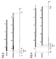
- FIG. 3 is a timing diagram of a time-slot illustrating communication between a sender and a receiver during upstream data transmission.
- the time-slot starts at a start time t s
- the receiver starts operation shortly afterwards at a time t 1 which in some embodiments of the invention may be the same time as the start time t s .
- the sender starts sending data at a time t 2 which is safely within the time-slot assigned to the sender.
- the clocks of the sender and the receiver according to which parallel data is read and serialised at the sender and deserialised and output at the receiver, respectively have a clock offset of t 2 minus t 1 .
- t 3 is the time at which the receiver receives the first bit or symbol sent by the sender at the time t 2 .
- the clock offset and the channel delay yield an offset time Dt.
- the guard-times of a time-division multiple access scheme will be chosen with regard to the expected delays/offsets. Thus, in a system where long delays/offsets may occur, guard-times will be long.
- the sender sends a stream of data packages (a, b, c, d) which are received within a stream of data packages (A, B, C, D, E) at the receiver.
- the offset time between the sender and the receiver is determined in order to reduce the idle time at the beginning of the time-slot. This is accomplished by sending a synchronisation signal (e.g. a byte of data containing a predetermined symbol, marked black in FIG. 3 ) which may be detected by the receiver regardless of the offset time.
- the receiver is adapted to search every two consecutive words of parallel output data for the synchronisation word and to determine the offset time.
- the offset time corresponds to the offset of the first bit of the synchronisation word to the first bit of the word of parallel data (that is the word boundary of the deserialised data) wherein the first bit of the synchronisation word is found multiplied by the transmission time of a bit.
- Transmission time of a bit or “bit transmission time” must not be misunderstood as the time a bit requires to travel from the sender to the receiver, in the scope of this document these terms refer to the reciprocal value of the data rate and hence to the time during which a bit is output by the sender.
- word transmission time or “transmission time of a word” refers to the bit transmission time multiplied by the serialisation/deserialisation ratio. Because of the fixed relation between a bit or a number of bits and the transmission time, a time such as the offset time may be expressed by means of a number of bits and vice versa.
- the receiver sends the determined offset time ⁇ t to the sender (thus, both the sender and the receiver are transceivers because they both comprise a respective sender and receiver circuit; when referring to FIGS. 1 and 2 , the term “sender” refers to the data source and "receiver” to the data sink rather than the actual components performing the sending/receiving action).
- the sender reduce the idle time at the beginning of the time-slot by referring to the offset time sent back by the receiver.
- idle time between the end time t e of a previous time-slot and the start time t s of the current time-slot can be shorter than in traditional systems. Only before the offset time is known, the sender must wait until some time after the start time t s of the time-slot thereby effectively increasing the guard-time to the time required in a traditional system.
- FIG. 4 is another timing diagram of the time-slot showing communication between the sender and the receiver after the offset time ⁇ t has been sent back to the sender.
- the sender now starts operation at an early start time t se which is one word transmission time before the previous time t 2 (relative to the start times of the respective time-slots) at which the sender started operation when the offset time was still unknown.
- the early start time t se is even before the start time t s of the time-slot.
- the output of the sender is disabled (muted) for a time corresponding to a word transmission time minus the offset time Dt.
- t 0 is the offset time before the time t 2 at which the sender had started operation in the previous occurrence of the time-slot.
- the data sent starting from to will arrive at the receiver at the time t 1 when the receiver starts receiving the first word of data.
- the time during which the sender does not send data is controlled with a granularity corresponding to a bit transmission time and therefore with a much finer granularity than in traditional systems. This enables reduction of idle times at the beginning of time-slots because the time during which the sender is active may be controlled more precisely.
- the sender can be controlled to reduce an idle-time at the end of the time-slot and hence to make use of the whole time-slot. This is accomplished by continuing to send data during a last word transmission that would not finish before the end time of the time-slot. In order to not violate the restrictions set by the time-slot, the sender is muted at a time t 4 one offset time before the end of the last word transmission.
- the invention has an advantage in that control of active time during which the sender is active and of idle time during which the sender may not send data over the channel is possible with a fine granularity and independent from the length and phase offsets of a word transmission at the sender and the receiver.
- the input data should be aligned with the active time of the sender (i.e. the time between t 0 and t 4 in FIG. 4 ).
- An embodiment of the sender therefore comprises a barrel-shifter which is adapted to barrel-shift the parallel input data by a number of bits corresponding to the offset time ⁇ t. Then, transmission of the first bit of serial data starts precisely at the time to when the sender is enabled.
- the remaining bits of parallel input data at the beginning (between t se and to) and at the end (after t 4 ) can be filled with arbitrary data or simply ones or zeroes as they never enter the channel.
- a positive side-effect of the barrel-shifting is that data will be aligned with the output clock at the receiver.
- Determining of the offset time ⁇ t can be performed only once at the start of the communication or several times during the communication (e.g. periodically) depending on channel characteristics.
- an optical fibre will provide constant characteristics over a long time such that the offset time ⁇ t will also remain constant and determination of the ⁇ t is only needed once.
- For channels with variable characteristics such as air periodical determination of the offset time ⁇ t will be necessary.
Landscapes
- Engineering & Computer Science (AREA)
- Computer Networks & Wireless Communication (AREA)
- Signal Processing (AREA)
- Time-Division Multiplex Systems (AREA)
Priority Applications (3)
| Application Number | Priority Date | Filing Date | Title |
|---|---|---|---|
| AT07012007T ATE511254T1 (de) | 2007-06-19 | 2007-06-19 | Verfahren zur datenübertragung und entsprechendes sende-/empfangsgerät |
| EP07012007A EP2015484B1 (de) | 2007-06-19 | 2007-06-19 | Verfahren zur Datenübertragung und entsprechendes Sende-/Empfangsgerät |
| PCT/EP2008/057686 WO2008155349A1 (en) | 2007-06-19 | 2008-06-18 | Method of data transmission and associated transceiver |
Applications Claiming Priority (1)
| Application Number | Priority Date | Filing Date | Title |
|---|---|---|---|
| EP07012007A EP2015484B1 (de) | 2007-06-19 | 2007-06-19 | Verfahren zur Datenübertragung und entsprechendes Sende-/Empfangsgerät |
Publications (2)
| Publication Number | Publication Date |
|---|---|
| EP2015484A1 true EP2015484A1 (de) | 2009-01-14 |
| EP2015484B1 EP2015484B1 (de) | 2011-05-25 |
Family
ID=38698885
Family Applications (1)
| Application Number | Title | Priority Date | Filing Date |
|---|---|---|---|
| EP07012007A Active EP2015484B1 (de) | 2007-06-19 | 2007-06-19 | Verfahren zur Datenübertragung und entsprechendes Sende-/Empfangsgerät |
Country Status (3)
| Country | Link |
|---|---|
| EP (1) | EP2015484B1 (de) |
| AT (1) | ATE511254T1 (de) |
| WO (1) | WO2008155349A1 (de) |
Cited By (2)
| Publication number | Priority date | Publication date | Assignee | Title |
|---|---|---|---|---|
| CN102860097A (zh) * | 2010-04-15 | 2013-01-02 | 摩托罗拉解决方案公司 | 用于同步直接模式时分多址(tdma)传输的方法 |
| US8976776B2 (en) | 2008-10-03 | 2015-03-10 | Motorola Solutions, Inc. | Method of efficiently synchronizing to a desired timeslot in a time division multiple access communication system |
Citations (3)
| Publication number | Priority date | Publication date | Assignee | Title |
|---|---|---|---|---|
| EP0678989A2 (de) * | 1994-04-21 | 1995-10-25 | ITALTEL SOCIETA ITALIANA TELECOMUNICAZIONI s.p.a. | Anordnung und Verfahren zur Steuerung der Takt bei digitalen Datenübertragung in einem passiven optischen TDMA system |
| US5710765A (en) * | 1995-11-06 | 1998-01-20 | Matsushita Electric Industrial Co., Ltd. | Method and apparatus for increasing the system efficiency of a TDMA system by reducing time slot guard time |
| WO1999000922A1 (de) * | 1997-06-28 | 1999-01-07 | Robert Bosch Gmbh | Verfahren für eine signalübertragung in einem netz |
-
2007
- 2007-06-19 AT AT07012007T patent/ATE511254T1/de not_active IP Right Cessation
- 2007-06-19 EP EP07012007A patent/EP2015484B1/de active Active
-
2008
- 2008-06-18 WO PCT/EP2008/057686 patent/WO2008155349A1/en not_active Ceased
Patent Citations (3)
| Publication number | Priority date | Publication date | Assignee | Title |
|---|---|---|---|---|
| EP0678989A2 (de) * | 1994-04-21 | 1995-10-25 | ITALTEL SOCIETA ITALIANA TELECOMUNICAZIONI s.p.a. | Anordnung und Verfahren zur Steuerung der Takt bei digitalen Datenübertragung in einem passiven optischen TDMA system |
| US5710765A (en) * | 1995-11-06 | 1998-01-20 | Matsushita Electric Industrial Co., Ltd. | Method and apparatus for increasing the system efficiency of a TDMA system by reducing time slot guard time |
| WO1999000922A1 (de) * | 1997-06-28 | 1999-01-07 | Robert Bosch Gmbh | Verfahren für eine signalübertragung in einem netz |
Cited By (3)
| Publication number | Priority date | Publication date | Assignee | Title |
|---|---|---|---|---|
| US8976776B2 (en) | 2008-10-03 | 2015-03-10 | Motorola Solutions, Inc. | Method of efficiently synchronizing to a desired timeslot in a time division multiple access communication system |
| CN102860097A (zh) * | 2010-04-15 | 2013-01-02 | 摩托罗拉解决方案公司 | 用于同步直接模式时分多址(tdma)传输的方法 |
| CN102860097B (zh) * | 2010-04-15 | 2015-06-24 | 摩托罗拉解决方案公司 | 用于同步直接模式时分多址(tdma)传输的方法 |
Also Published As
| Publication number | Publication date |
|---|---|
| EP2015484B1 (de) | 2011-05-25 |
| ATE511254T1 (de) | 2011-06-15 |
| WO2008155349A1 (en) | 2008-12-24 |
Similar Documents
| Publication | Publication Date | Title |
|---|---|---|
| US7184664B2 (en) | Method and system for providing a return path for signals generated by legacy terminals in an optical network | |
| US5398129A (en) | Passive optical telecommunication system for narrow band and broadband integrated services digital networks | |
| KR100639823B1 (ko) | 전광 슬롯형 링 다이나믹 통신망을 위한 동기화 시스템 | |
| KR100283462B1 (ko) | 프레임을 기초로한 데이타 전송 | |
| US8565605B2 (en) | Burst mode to continuous mode converter | |
| US5642351A (en) | Wide area fiber and TV cable fast packet cell network | |
| EP0748077A2 (de) | Übertragungssystem mit asymmetrischem Pingpong-Verfahren | |
| US5349461A (en) | Simultaneous bidirectional digital data transmission over a single line at a common frequency on an optical waveguide | |
| US7593639B2 (en) | Method and system for providing a return path for signals generated by legacy terminals in an optical network | |
| US20070116465A1 (en) | Systems and methods for dynamic alignment of data bursts conveyed over a passive optical net work | |
| EP2093917A1 (de) | Verfahren zur Bandbreitenzuweisung, optischer Leitungsendgerät, Teilnehmerstation und Kommunikationssystem | |
| US5654815A (en) | Synchronization method as well as synchronizing units, terminal and exchange therefor | |
| KR20040026177A (ko) | 방송 및 통신 신호를 수용할 수 있는 광가입자망 시스템 | |
| EP2015484B1 (de) | Verfahren zur Datenübertragung und entsprechendes Sende-/Empfangsgerät | |
| US10637601B2 (en) | Communications network | |
| CN115589271B (zh) | 信号同步系统、方法、装置及电子设备 | |
| US5974103A (en) | Deterministic exchange of data between synchronised systems separated by a distance | |
| US7301960B2 (en) | Apparatus for and method of control and communication of multiple stations in a TDM network | |
| US7154879B1 (en) | Point to multipoint network | |
| WO2002098162A1 (fr) | Procede reposant sur la transmission par fond de panier de donnees pour circuit de multiplexage temporel et connecteur passerelle | |
| US4594707A (en) | High speed limited distance multiplexed data communications modem using a single twisted pair of conductors | |
| EP4412239B1 (de) | Steuerung der onu-aktivierung in pon mit hoher bitrate | |
| KR100621887B1 (ko) | 시분할 다중 방식 시스템의 동기신호 조정 장치 | |
| KR20250140264A (ko) | 수동형 광 가입자망 데이터 동기 획득 장치 및 방법 | |
| EP1206064A1 (de) | Verfahren und Vorrichtung zur Synchronisierung von Bitsignalen |
Legal Events
| Date | Code | Title | Description |
|---|---|---|---|
| PUAI | Public reference made under article 153(3) epc to a published international application that has entered the european phase |
Free format text: ORIGINAL CODE: 0009012 |
|
| PUAI | Public reference made under article 153(3) epc to a published international application that has entered the european phase |
Free format text: ORIGINAL CODE: 0009012 |
|
| AK | Designated contracting states |
Kind code of ref document: A1 Designated state(s): AT BE BG CH CY CZ DE DK EE ES FI FR GB GR HU IE IS IT LI LT LU LV MC MT NL PL PT RO SE SI SK TR |
|
| AX | Request for extension of the european patent |
Extension state: AL BA HR MK RS |
|
| AKX | Designation fees paid | ||
| RBV | Designated contracting states (corrected) |
Designated state(s): AT BE BG CH CY CZ DE DK EE ES FI FR GB GR HU IE IS IT LI LT LU LV MC MT NL PL PT RO SE SI SK TR |
|
| 17P | Request for examination filed |
Effective date: 20090714 |
|
| 17Q | First examination report despatched |
Effective date: 20091009 |
|
| GRAP | Despatch of communication of intention to grant a patent |
Free format text: ORIGINAL CODE: EPIDOSNIGR1 |
|
| GRAS | Grant fee paid |
Free format text: ORIGINAL CODE: EPIDOSNIGR3 |
|
| GRAA | (expected) grant |
Free format text: ORIGINAL CODE: 0009210 |
|
| AK | Designated contracting states |
Kind code of ref document: B1 Designated state(s): AT BE BG CH CY CZ DE DK EE ES FI FR GB GR HU IE IS IT LI LT LU LV MC MT NL PL PT RO SE SI SK TR |
|
| REG | Reference to a national code |
Ref country code: GB Ref legal event code: FG4D |
|
| REG | Reference to a national code |
Ref country code: CH Ref legal event code: EP |
|
| REG | Reference to a national code |
Ref country code: IE Ref legal event code: FG4D |
|
| REG | Reference to a national code |
Ref country code: DE Ref legal event code: R096 Ref document number: 602007014840 Country of ref document: DE Effective date: 20110707 |
|
| REG | Reference to a national code |
Ref country code: NL Ref legal event code: VDEP Effective date: 20110525 |
|
| PG25 | Lapsed in a contracting state [announced via postgrant information from national office to epo] |
Ref country code: PT Free format text: LAPSE BECAUSE OF FAILURE TO SUBMIT A TRANSLATION OF THE DESCRIPTION OR TO PAY THE FEE WITHIN THE PRESCRIBED TIME-LIMIT Effective date: 20110926 Ref country code: SE Free format text: LAPSE BECAUSE OF FAILURE TO SUBMIT A TRANSLATION OF THE DESCRIPTION OR TO PAY THE FEE WITHIN THE PRESCRIBED TIME-LIMIT Effective date: 20110525 Ref country code: LT Free format text: LAPSE BECAUSE OF FAILURE TO SUBMIT A TRANSLATION OF THE DESCRIPTION OR TO PAY THE FEE WITHIN THE PRESCRIBED TIME-LIMIT Effective date: 20110525 |
|
| PG25 | Lapsed in a contracting state [announced via postgrant information from national office to epo] |
Ref country code: SI Free format text: LAPSE BECAUSE OF FAILURE TO SUBMIT A TRANSLATION OF THE DESCRIPTION OR TO PAY THE FEE WITHIN THE PRESCRIBED TIME-LIMIT Effective date: 20110525 Ref country code: IS Free format text: LAPSE BECAUSE OF FAILURE TO SUBMIT A TRANSLATION OF THE DESCRIPTION OR TO PAY THE FEE WITHIN THE PRESCRIBED TIME-LIMIT Effective date: 20110925 Ref country code: AT Free format text: LAPSE BECAUSE OF FAILURE TO SUBMIT A TRANSLATION OF THE DESCRIPTION OR TO PAY THE FEE WITHIN THE PRESCRIBED TIME-LIMIT Effective date: 20110525 Ref country code: CY Free format text: LAPSE BECAUSE OF FAILURE TO SUBMIT A TRANSLATION OF THE DESCRIPTION OR TO PAY THE FEE WITHIN THE PRESCRIBED TIME-LIMIT Effective date: 20110525 Ref country code: GR Free format text: LAPSE BECAUSE OF FAILURE TO SUBMIT A TRANSLATION OF THE DESCRIPTION OR TO PAY THE FEE WITHIN THE PRESCRIBED TIME-LIMIT Effective date: 20110826 Ref country code: ES Free format text: LAPSE BECAUSE OF FAILURE TO SUBMIT A TRANSLATION OF THE DESCRIPTION OR TO PAY THE FEE WITHIN THE PRESCRIBED TIME-LIMIT Effective date: 20110905 Ref country code: BE Free format text: LAPSE BECAUSE OF FAILURE TO SUBMIT A TRANSLATION OF THE DESCRIPTION OR TO PAY THE FEE WITHIN THE PRESCRIBED TIME-LIMIT Effective date: 20110525 Ref country code: LV Free format text: LAPSE BECAUSE OF FAILURE TO SUBMIT A TRANSLATION OF THE DESCRIPTION OR TO PAY THE FEE WITHIN THE PRESCRIBED TIME-LIMIT Effective date: 20110525 Ref country code: FI Free format text: LAPSE BECAUSE OF FAILURE TO SUBMIT A TRANSLATION OF THE DESCRIPTION OR TO PAY THE FEE WITHIN THE PRESCRIBED TIME-LIMIT Effective date: 20110525 |
|
| PG25 | Lapsed in a contracting state [announced via postgrant information from national office to epo] |
Ref country code: MT Free format text: LAPSE BECAUSE OF FAILURE TO SUBMIT A TRANSLATION OF THE DESCRIPTION OR TO PAY THE FEE WITHIN THE PRESCRIBED TIME-LIMIT Effective date: 20110525 Ref country code: NL Free format text: LAPSE BECAUSE OF FAILURE TO SUBMIT A TRANSLATION OF THE DESCRIPTION OR TO PAY THE FEE WITHIN THE PRESCRIBED TIME-LIMIT Effective date: 20110525 |
|
| PG25 | Lapsed in a contracting state [announced via postgrant information from national office to epo] |
Ref country code: EE Free format text: LAPSE BECAUSE OF FAILURE TO SUBMIT A TRANSLATION OF THE DESCRIPTION OR TO PAY THE FEE WITHIN THE PRESCRIBED TIME-LIMIT Effective date: 20110525 Ref country code: CZ Free format text: LAPSE BECAUSE OF FAILURE TO SUBMIT A TRANSLATION OF THE DESCRIPTION OR TO PAY THE FEE WITHIN THE PRESCRIBED TIME-LIMIT Effective date: 20110525 |
|
| REG | Reference to a national code |
Ref country code: CH Ref legal event code: PL |
|
| PG25 | Lapsed in a contracting state [announced via postgrant information from national office to epo] |
Ref country code: RO Free format text: LAPSE BECAUSE OF FAILURE TO SUBMIT A TRANSLATION OF THE DESCRIPTION OR TO PAY THE FEE WITHIN THE PRESCRIBED TIME-LIMIT Effective date: 20110525 Ref country code: PL Free format text: LAPSE BECAUSE OF FAILURE TO SUBMIT A TRANSLATION OF THE DESCRIPTION OR TO PAY THE FEE WITHIN THE PRESCRIBED TIME-LIMIT Effective date: 20110525 Ref country code: DK Free format text: LAPSE BECAUSE OF FAILURE TO SUBMIT A TRANSLATION OF THE DESCRIPTION OR TO PAY THE FEE WITHIN THE PRESCRIBED TIME-LIMIT Effective date: 20110525 Ref country code: SK Free format text: LAPSE BECAUSE OF FAILURE TO SUBMIT A TRANSLATION OF THE DESCRIPTION OR TO PAY THE FEE WITHIN THE PRESCRIBED TIME-LIMIT Effective date: 20110525 |
|
| REG | Reference to a national code |
Ref country code: IE Ref legal event code: MM4A |
|
| PLBE | No opposition filed within time limit |
Free format text: ORIGINAL CODE: 0009261 |
|
| STAA | Information on the status of an ep patent application or granted ep patent |
Free format text: STATUS: NO OPPOSITION FILED WITHIN TIME LIMIT |
|
| PG25 | Lapsed in a contracting state [announced via postgrant information from national office to epo] |
Ref country code: CH Free format text: LAPSE BECAUSE OF NON-PAYMENT OF DUE FEES Effective date: 20110630 Ref country code: IE Free format text: LAPSE BECAUSE OF NON-PAYMENT OF DUE FEES Effective date: 20110619 Ref country code: LI Free format text: LAPSE BECAUSE OF NON-PAYMENT OF DUE FEES Effective date: 20110630 |
|
| 26N | No opposition filed |
Effective date: 20120228 |
|
| PG25 | Lapsed in a contracting state [announced via postgrant information from national office to epo] |
Ref country code: IT Free format text: LAPSE BECAUSE OF FAILURE TO SUBMIT A TRANSLATION OF THE DESCRIPTION OR TO PAY THE FEE WITHIN THE PRESCRIBED TIME-LIMIT Effective date: 20110525 |
|
| REG | Reference to a national code |
Ref country code: DE Ref legal event code: R097 Ref document number: 602007014840 Country of ref document: DE Effective date: 20120228 |
|
| PG25 | Lapsed in a contracting state [announced via postgrant information from national office to epo] |
Ref country code: MC Free format text: LAPSE BECAUSE OF NON-PAYMENT OF DUE FEES Effective date: 20110630 |
|
| PG25 | Lapsed in a contracting state [announced via postgrant information from national office to epo] |
Ref country code: LU Free format text: LAPSE BECAUSE OF NON-PAYMENT OF DUE FEES Effective date: 20110619 |
|
| PG25 | Lapsed in a contracting state [announced via postgrant information from national office to epo] |
Ref country code: BG Free format text: LAPSE BECAUSE OF FAILURE TO SUBMIT A TRANSLATION OF THE DESCRIPTION OR TO PAY THE FEE WITHIN THE PRESCRIBED TIME-LIMIT Effective date: 20110825 |
|
| PG25 | Lapsed in a contracting state [announced via postgrant information from national office to epo] |
Ref country code: TR Free format text: LAPSE BECAUSE OF FAILURE TO SUBMIT A TRANSLATION OF THE DESCRIPTION OR TO PAY THE FEE WITHIN THE PRESCRIBED TIME-LIMIT Effective date: 20110525 |
|
| PG25 | Lapsed in a contracting state [announced via postgrant information from national office to epo] |
Ref country code: HU Free format text: LAPSE BECAUSE OF FAILURE TO SUBMIT A TRANSLATION OF THE DESCRIPTION OR TO PAY THE FEE WITHIN THE PRESCRIBED TIME-LIMIT Effective date: 20110525 |
|
| REG | Reference to a national code |
Ref country code: DE Ref legal event code: R081 Ref document number: 602007014840 Country of ref document: DE Owner name: NOKIA SOLUTIONS AND NETWORKS OY, FI Free format text: FORMER OWNER: NOKIA SIEMENS NETWORKS OY, ESPOO, FI Effective date: 20140521 |
|
| REG | Reference to a national code |
Ref country code: FR Ref legal event code: CD Owner name: NOKIA SOLUTIONS AND NETWORKS OY, FI Effective date: 20141201 |
|
| REG | Reference to a national code |
Ref country code: FR Ref legal event code: PLFP Year of fee payment: 10 |
|
| REG | Reference to a national code |
Ref country code: FR Ref legal event code: PLFP Year of fee payment: 11 |
|
| REG | Reference to a national code |
Ref country code: FR Ref legal event code: PLFP Year of fee payment: 12 |
|
| PGFP | Annual fee paid to national office [announced via postgrant information from national office to epo] |
Ref country code: DE Payment date: 20250429 Year of fee payment: 19 |
|
| PGFP | Annual fee paid to national office [announced via postgrant information from national office to epo] |
Ref country code: GB Payment date: 20250501 Year of fee payment: 19 |
|
| PGFP | Annual fee paid to national office [announced via postgrant information from national office to epo] |
Ref country code: FR Payment date: 20250508 Year of fee payment: 19 |