EP2015194A1 - Method for data transfer between host and device - Google Patents
Method for data transfer between host and device Download PDFInfo
- Publication number
- EP2015194A1 EP2015194A1 EP07301188A EP07301188A EP2015194A1 EP 2015194 A1 EP2015194 A1 EP 2015194A1 EP 07301188 A EP07301188 A EP 07301188A EP 07301188 A EP07301188 A EP 07301188A EP 2015194 A1 EP2015194 A1 EP 2015194A1
- Authority
- EP
- European Patent Office
- Prior art keywords
- memory
- pipes
- pipe
- host
- ctrl2
- Prior art date
- Legal status (The legal status is an assumption and is not a legal conclusion. Google has not performed a legal analysis and makes no representation as to the accuracy of the status listed.)
- Withdrawn
Links
Images


Classifications
-
- G—PHYSICS
- G06—COMPUTING; CALCULATING OR COUNTING
- G06F—ELECTRIC DIGITAL DATA PROCESSING
- G06F13/00—Interconnection of, or transfer of information or other signals between, memories, input/output devices or central processing units
- G06F13/38—Information transfer, e.g. on bus
- G06F13/42—Bus transfer protocol, e.g. handshake; Synchronisation
- G06F13/4282—Bus transfer protocol, e.g. handshake; Synchronisation on a serial bus, e.g. I2C bus, SPI bus
-
- G—PHYSICS
- G06—COMPUTING; CALCULATING OR COUNTING
- G06F—ELECTRIC DIGITAL DATA PROCESSING
- G06F13/00—Interconnection of, or transfer of information or other signals between, memories, input/output devices or central processing units
- G06F13/10—Program control for peripheral devices
- G06F13/102—Program control for peripheral devices where the programme performs an interfacing function, e.g. device driver
-
- G—PHYSICS
- G06—COMPUTING; CALCULATING OR COUNTING
- G06F—ELECTRIC DIGITAL DATA PROCESSING
- G06F2213/00—Indexing scheme relating to interconnection of, or transfer of information or other signals between, memories, input/output devices or central processing units
- G06F2213/0042—Universal serial bus [USB]
Definitions
- the present invention relates to a method for data transfer between a host and a device as well as to respective apparatus.
- a host is seen as a communication apparatus which organizes data traffic.
- a device is seen as dependent on the host. In a tiered-star topology there are usually multiple devices connected to one host.
- USB protocol In general, during data communication using for example Universal Serial Bus protocol often referred to as USB protocol, the available memory in a host may be divided in multiple segments. Each memory segment is allocated to certain functionality, for example being a buffer for bi-directional control traffic, being a buffer for incoming data traffic or being a buffer for outgoing data traffic. Memory demands are strongly dependent on the used USB device.
- the requirements of a USB device can be defined full-custom by the device vendor or a device can belong to a certain USB class.
- USB classes can be for example Human Interface Device class, also called HID class, Mass Storage Device class, Video Device class, Hubs, Wireless controllers and more.
- a USB class defines certain behavior of a device belonging to this class.
- a device belonging to the mass storage class for example features large bursty data. Therefore, it uses bulk transfer as USB endpoint type. Bulk transfer does not guarantee any latency or minimum bandwidth and will use the un-allocated bus bandwidth.
- mass storage devices are characterized by having data streams mainly from the device to the host, the so called 'reading', or from the host to the device, the so called 'writing'. There is no bidirectional data transmission in terms of equal data rates from the device to the host and vice versa.
- USB communication is performed through pipes, each pipe is connected to an endpoint at the host side as well as at the device side. Data transmission on each endpoint can be independent from each other. Data transmission between two endpoints is always unidirectional. For bidirectional data transmission at least two endpoints in the host and two corresponding endpoints in the device are necessary. Sole exceptions are control pipes which work bidirectional. Between each host and each device only one control pipe is established.
- Each endpoint allocates a certain amount of memory to ensure functionality.
- the size of this memory determines the speed of the connection up to a certain extent.
- Patent Abstract of JP2006252334 discloses a data transfer control method and a data transfer controller for allocating a fixed size of buffer area on a shared memory to a pipe. Furthermore, memory of a fixed size is allocated to each port.
- memory of a fixed size is allocated to each pipe and data transfer is mainly in one direction as described above, a substantial amount of allocated memory is used inefficiently. Furthermore, if memory of a fixed size is allocated to each port and thus to each device connected, then a lot of memory will be wasted if a device requires small memory.
- the available buffer memory in a host device is divided into multiple segments. If a device is connected to a port, after doing some control transfer performed over a control pipe, the device and the host will open other device specific pipes, each one terminated with an endpoint in the device. Establishing a bidirectional communication link, an IN pipe and an OUT pipe in the host is necessary as well as the corresponding endpoints in the device.
- a memory segment is allocated to an IN-OUT pipe pair. This memory is assigned to either the IN pipe or the OUT pipe depending on the direction of communication. Following the fundamental idea of the invention leads to unidirectional transmission because memory used for a certain device is allocated only to IN pipes or OUT pipes at a certain time.
- Bidirectional transmission is achieved during switching the memory between IN pipes and OUT pipes over time. Hence, direction of data transmission can be changed sequentially. Thus, memory is only allocated to endpoints which are currently in use and no memory is allocated but no used.
- the proposed solution has the advantage that waste of memory is almost omitted and uses the overall available memory efficiently.
- An IN-OUT pipe pair is not limited to have only one memory area assigned to. Assigning multiple memory segments to a single IN-OUT pipe pair is also within the scope of the invention and provides faster transmission. In case of multiple pipes of the same type belonging to one port, meaning multiple IN pipes or multiple OUT pipes, multiple memory segments can be switched between different types of pipes or can be switched between the same types of pipes as described below.
- one or multiple flags are used to indicate that the memory segment is allocated to an IN pipe or OUT pipe.
- This memory segment can be switched with low complexity and the flag can also be used to identify the currently active pipes. This allows fast reallocation of a certain memory segment and keeps the system flexible.
- two flags indicate the affiliation of a memory segment.
- the device which is connected via this memory segment, is identified by a first flag.
- the second flag indicates how many pipes and hence how many endpoints in the device have access to this memory segment.
- the invention is used for bulk transfer mode.
- This endpoint type is characterized by bursty data which is sent in many cases mainly in one direction.
- either IN pipes or OUT pipes are mainly unused.
- Further packet size can be relatively big which demands large buffer sizes.
- Effective use of the available memory by a smart memory allocation system as described above leads to significant performance improvements.
- switching between different types of pipes is performed such that memory is allocated to IN pipes of a port in case of data sent to the host via this port and memory is allocated to the OUT pipes of a port in case the host is sending data to the corresponding device.
- this type of allocation memory is used most efficiently.
- the number of memory segments assigned for these pipes may exceed the number of pipes of a certain type.
- more memory segments are assigned than IN pipes or OUT pipes are available.
- different numbers of memory segments can be assigned to different pipes of one type.
- a certain pipe type may be an IN pipe.
- An OUT pipe is considered as another pipe type.
- the number of memory segments assigned to a certain pipe may change during time according to the data traffic.
- the whole memory available for data transfer is shared.
- the whole available buffer memory is divided into segments and all segments can be assigned based on the need of the endpoint. This guarantees the use of all available memory more efficiently which can not be done using a method known in the art. Sharing all memory is made possible according to the invention. Even if the whole available memory is allocated, a new device can still be connected to another port because the memory allocation system is flexible and memory can be allocated to a newly included device without crashing the system. This is true under the assumption that multiple memory segments are assigned at least to one of the existing pipes, hence, there is no lack of memory.
- memory segments assigned to control pipes are not switched. Memory demands for the control pipes are normally limited, because data rates on the control pipes are low. Transmission on control pipes is bidirectional and control traffic can be used to achieve important features such as clearing stall condition happened to other endpoints. Therefore, assigning fixed memory to control endpoint does not waste much memory and further does not differ from the basic concept of the invention to use common memory for incoming and outgoing traffic. Further, assigning fixed memory to the control pipes reduces breakdown risk of the system.
- the invention is implemented for data transfer according to USB protocol.
- the invention can also be advantageously used with other protocols supporting sequential data transfer through pipes or other virtual paths.
- Fig. 1 shows two device apparatus D1 and D2 connected to a host apparatus H in an exemplary embodiment.
- the description applies to similar embodiments, having multiple or only one device connected to.
- only the host H uses a memory sharing algorithm.
- the devices D1, D2 allocate separate memory to each endpoint. Nevertheless, memory sharing can be implemented similarly in the devices. Also more than one memory segment can be assigned to one endpoint in the devices.
- Data communication between the host H and the fist device D1 is done via one in pipe B_I1 and one out pipe B_O1. Further a bidirectional control pipe CTRL1 exists.
- memory HMC1 is assigned separately to the control pipe CTRL1. Nevertheless, it is also within the scope of the invention to apply shared memory segments to the control pipes.
- Shared memory HMB1 is assigned to the in pipe B_I1 and the out pipe B_O1.
- This shared memory may consist of one memory segment or multiple memory segments. The memory is assigned in case of incoming data to the in pipe B_I1. In case of outgoing traffic memory is assigned to the out pipe B_O1. This is indicated by the arrows.
- Data communication between the host H and the second device D2 is done via two in pipes B_I2, B_I3 and two out pipes B_O2, B_O3. Further a bidirectional control pipe CTRL2 exists.
- memory HMC2 is assigned separately to the control pipe CTRL2. Nevertheless, it is also within the scope of the invention to apply shared memory segments to the control pipes.
- Shared memory HMB2, HMB3, HMB4 is assigned to the in pipes B_I2, B_I3 and the out pipes B_O2, B_O3.
- This shared memory may consist of multiple memory segments.
- the number of memory segments corresponds to the number of in or out pipes or the number of memory segments is higher than the number of in or out pipes.
- the memory segments are assigned in case of incoming data to the in pipes B_I2, B_I3.
- In case of outgoing traffic memory is assigned to the out pipe B_O2, B_O3. This is indicated by the arrows.
- a flag or another distinction means marks each memory segment to which endpoint it belongs. Assigning and reassigning the memory segments to the corresponding pipes can be done for example like described below.
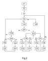
- Fig. 2 illustrates schematically a method of memory sharing in a host according to the invention in detail.
- a control pipe is established for the corresponding port and memory is assigned to this control pipe S2. Further setup is done S3 and mode of communication is identified according to the device request S4. In case of time dependent devices N4, interrupt transfer is established for example. Memory is assigned to in pipes and out pipes separately S20 and an USB connection known in the art is established. In case of transfer using high data rates Y4, bulk transfer is established for example, which does not have such strict latency requirements. Also some kinds of isochronous transfer fall within the scope of this category. If it is decided to work sequentially and to share memory according to the presented invention Y4, sequential mode is established S10.
- a decision S11 is made if a single in and a single out pipe is established N11 or if multiple in pipes and/or multiple out pipes are established Y11 according to the device requirement and according to the host resources.
- memory is allocated to this pipe pair S30. This can be a sole memory segment or multiple memory segments to enhance the buffer capacity.
- Decision is made if receive mode R31 or send mode T31 is established S31 according to the protocol. In the first case R31, memory is assigned to the in pipe S50 and data are received S51. In the later case T31, memory is assigned to the out pipe S60 and data are sent S61. Switching from receive R31 to send mode T31 and vice versa is possible using decision S31.
- a new transmission mode can be chosen for the same device S4 or the device can be disabled alternatively which is not shown in the diagram.
- memory segments are allocated to pipe pairs S40. Multiple memory segments can be allocated to multiple pipes in various ways, for example as described above.
- Fig. 3 illustrates schematically how a new endpoint in a device can be established sharing memory already assigned to the device.
- Communication is established in sequential mode S10 and memory is allocated S30, S40 as described above. If a new pipe and an according endpoint in the device are established, it is checked if already assigned memory is available S100. If memory is available Y100 this memory segment will be used for the new pipe too and the flag of the memory segment, indication how many pipes have access to this segment is increased by one S110. Multiple in or out pipes can use the same memory segment as long they work sequentially. If no memory is available, a new memory segment is assigned to this device, the flag indicating to which device the segment belongs is set and the flag indicating how many pipes have access to this segment is set to one S120.
Landscapes
- Engineering & Computer Science (AREA)
- Theoretical Computer Science (AREA)
- Physics & Mathematics (AREA)
- General Engineering & Computer Science (AREA)
- General Physics & Mathematics (AREA)
- Information Transfer Systems (AREA)
- Small-Scale Networks (AREA)
Priority Applications (6)
| Application Number | Priority Date | Filing Date | Title |
|---|---|---|---|
| EP07301188A EP2015194A1 (en) | 2007-06-29 | 2007-06-29 | Method for data transfer between host and device |
| TW097119978A TWI446182B (zh) | 2007-06-29 | 2008-05-30 | 主機和機件間經過管路之資料轉移方法及裝置 |
| EP08158815.4A EP2017740B1 (en) | 2007-06-29 | 2008-06-24 | Method for data transfer between host and device |
| US12/215,139 US8219726B2 (en) | 2007-06-29 | 2008-06-25 | Method for data transfer between host and device |
| JP2008167256A JP5367310B2 (ja) | 2007-06-29 | 2008-06-26 | ホストとデバイスの間のデータ転送のための方法および機器 |
| CN2008101274145A CN101334763B (zh) | 2007-06-29 | 2008-06-30 | 主机与设备之间的数据传送方法 |
Applications Claiming Priority (1)
| Application Number | Priority Date | Filing Date | Title |
|---|---|---|---|
| EP07301188A EP2015194A1 (en) | 2007-06-29 | 2007-06-29 | Method for data transfer between host and device |
Publications (1)
| Publication Number | Publication Date |
|---|---|
| EP2015194A1 true EP2015194A1 (en) | 2009-01-14 |
Family
ID=38739509
Family Applications (2)
| Application Number | Title | Priority Date | Filing Date |
|---|---|---|---|
| EP07301188A Withdrawn EP2015194A1 (en) | 2007-06-29 | 2007-06-29 | Method for data transfer between host and device |
| EP08158815.4A Expired - Fee Related EP2017740B1 (en) | 2007-06-29 | 2008-06-24 | Method for data transfer between host and device |
Family Applications After (1)
| Application Number | Title | Priority Date | Filing Date |
|---|---|---|---|
| EP08158815.4A Expired - Fee Related EP2017740B1 (en) | 2007-06-29 | 2008-06-24 | Method for data transfer between host and device |
Country Status (5)
| Country | Link |
|---|---|
| US (1) | US8219726B2 (zh) |
| EP (2) | EP2015194A1 (zh) |
| JP (1) | JP5367310B2 (zh) |
| CN (1) | CN101334763B (zh) |
| TW (1) | TWI446182B (zh) |
Families Citing this family (2)
| Publication number | Priority date | Publication date | Assignee | Title |
|---|---|---|---|---|
| TWI497414B (zh) * | 2009-06-23 | 2015-08-21 | Phison Electronics Corp | 檔案執行方法及系統 |
| CN114461536A (zh) * | 2020-11-10 | 2022-05-10 | 瑞昱半导体股份有限公司 | 查找表建立及内存地址查询方法 |
Citations (5)
| Publication number | Priority date | Publication date | Assignee | Title |
|---|---|---|---|---|
| US20010056513A1 (en) * | 2000-06-21 | 2001-12-27 | Nec Corporation | Data transfer control method and controller for universal serial bus interface |
| US20040093454A1 (en) * | 2002-11-07 | 2004-05-13 | Teng Peter Chu Tin | USB endpoint controller flexible memory management |
| US20040133708A1 (en) * | 2003-01-06 | 2004-07-08 | Netchip Technology, Inc. | Virtual endpoint for USB devices |
| US20050010702A1 (en) * | 2003-05-20 | 2005-01-13 | Seiko Epson Corporation | Data transfer control device, electronic instrument, and data transfer control method |
| EP1698976A1 (en) * | 2005-03-03 | 2006-09-06 | Siemens Aktiengesellschaft | Priority-sensitive reallocation of buffer space |
Family Cites Families (2)
| Publication number | Priority date | Publication date | Assignee | Title |
|---|---|---|---|---|
| JP2002312296A (ja) * | 2001-04-10 | 2002-10-25 | Nec Microsystems Ltd | 周辺装置のusbインタフェース装置、その制御方法およびプログラム並びにusbインタフェースシステム |
| JP2006252334A (ja) | 2005-03-11 | 2006-09-21 | Seiko Epson Corp | データ転送制御方法、データ転送制御装置 |
-
2007
- 2007-06-29 EP EP07301188A patent/EP2015194A1/en not_active Withdrawn
-
2008
- 2008-05-30 TW TW097119978A patent/TWI446182B/zh not_active IP Right Cessation
- 2008-06-24 EP EP08158815.4A patent/EP2017740B1/en not_active Expired - Fee Related
- 2008-06-25 US US12/215,139 patent/US8219726B2/en active Active
- 2008-06-26 JP JP2008167256A patent/JP5367310B2/ja not_active Expired - Fee Related
- 2008-06-30 CN CN2008101274145A patent/CN101334763B/zh not_active Expired - Fee Related
Patent Citations (5)
| Publication number | Priority date | Publication date | Assignee | Title |
|---|---|---|---|---|
| US20010056513A1 (en) * | 2000-06-21 | 2001-12-27 | Nec Corporation | Data transfer control method and controller for universal serial bus interface |
| US20040093454A1 (en) * | 2002-11-07 | 2004-05-13 | Teng Peter Chu Tin | USB endpoint controller flexible memory management |
| US20040133708A1 (en) * | 2003-01-06 | 2004-07-08 | Netchip Technology, Inc. | Virtual endpoint for USB devices |
| US20050010702A1 (en) * | 2003-05-20 | 2005-01-13 | Seiko Epson Corporation | Data transfer control device, electronic instrument, and data transfer control method |
| EP1698976A1 (en) * | 2005-03-03 | 2006-09-06 | Siemens Aktiengesellschaft | Priority-sensitive reallocation of buffer space |
Also Published As
| Publication number | Publication date |
|---|---|
| CN101334763B (zh) | 2013-04-17 |
| EP2017740A2 (en) | 2009-01-21 |
| JP5367310B2 (ja) | 2013-12-11 |
| TWI446182B (zh) | 2014-07-21 |
| US8219726B2 (en) | 2012-07-10 |
| CN101334763A (zh) | 2008-12-31 |
| US20090043923A1 (en) | 2009-02-12 |
| EP2017740B1 (en) | 2020-04-08 |
| EP2017740A3 (en) | 2015-06-17 |
| JP2009015837A (ja) | 2009-01-22 |
| TW200900947A (en) | 2009-01-01 |
Similar Documents
| Publication | Publication Date | Title |
|---|---|---|
| US6877048B2 (en) | Dynamic memory allocation between inbound and outbound buffers in a protocol handler | |
| KR20110113351A (ko) | 네트워크 효율성을 고려한 SoC 기반 시스템 네트워크에서의 인터페이스 장치의 통신방법 및 그에 의해 통신하는 인터페이스 장치 | |
| CN107852423B (zh) | 用于usb 2.0带宽保留的方法及系统 | |
| KR100557215B1 (ko) | 유에스비 디바이스의 엔드포인트 제어 장치 및 그 방법 | |
| US7974190B2 (en) | Dynamic queue memory allocation with flow control | |
| CN102750245B (zh) | 报文接收方法、报文接收模块、装置及系统 | |
| CN100589393C (zh) | 一种网卡实现双协议栈切换的方法 | |
| CN104123188A (zh) | 一种资源分配方法及相关装置 | |
| EP2017740B1 (en) | Method for data transfer between host and device | |
| GB2412757A (en) | USB host having multiple endpoints which can be dynamically re-allocated to USB devices | |
| KR20040106665A (ko) | 송수신 흐름에 따라 공유 버퍼 메모리의 할당량을제어하는 송수신 네트워크 제어기 및 그 방법 | |
| KR101197294B1 (ko) | QoS 및 전송 효율 개선을 위한 SoC 기반 시스템 네트워크에서의 인터페이스 장치의 통신방법 | |
| AU624745B2 (en) | Packet/fast packet switch for voice and data | |
| CN115442239B (zh) | 带宽资源分配方法、PCIe通道切换器及电子设备 | |
| US20090313393A1 (en) | Method of increasing efficiency of end point memory in usb devices | |
| CN117453615A (zh) | 数据传输方法、装置、电子设备及存储介质 | |
| KR100190388B1 (ko) | 밴드창 가변할당 장치 및 그 방법 | |
| JP2005143009A (ja) | 構内交換機 |
Legal Events
| Date | Code | Title | Description |
|---|---|---|---|
| PUAI | Public reference made under article 153(3) epc to a published international application that has entered the european phase |
Free format text: ORIGINAL CODE: 0009012 |
|
| AK | Designated contracting states |
Kind code of ref document: A1 Designated state(s): AT BE BG CH CY CZ DE DK EE ES FI FR GB GR HU IE IS IT LI LT LU LV MC MT NL PL PT RO SE SI SK TR |
|
| AX | Request for extension of the european patent |
Extension state: AL BA HR MK RS |
|
| AKX | Designation fees paid | ||
| STAA | Information on the status of an ep patent application or granted ep patent |
Free format text: STATUS: THE APPLICATION IS DEEMED TO BE WITHDRAWN |
|
| 18D | Application deemed to be withdrawn |
Effective date: 20090715 |
|
| REG | Reference to a national code |
Ref country code: DE Ref legal event code: 8566 |