EP2015156B1 - Operating procedure for a home automation installation and home automation installation for its implementation - Google Patents
Operating procedure for a home automation installation and home automation installation for its implementation Download PDFInfo
- Publication number
- EP2015156B1 EP2015156B1 EP08159836A EP08159836A EP2015156B1 EP 2015156 B1 EP2015156 B1 EP 2015156B1 EP 08159836 A EP08159836 A EP 08159836A EP 08159836 A EP08159836 A EP 08159836A EP 2015156 B1 EP2015156 B1 EP 2015156B1
- Authority
- EP
- European Patent Office
- Prior art keywords
- information
- operating method
- travel
- movable element
- actuator
- Prior art date
- Legal status (The legal status is an assumption and is not a legal conclusion. Google has not performed a legal analysis and makes no representation as to the accuracy of the status listed.)
- Active
Links
- 238000009434 installation Methods 0.000 title claims description 26
- 238000011017 operating method Methods 0.000 title claims description 16
- 238000001514 detection method Methods 0.000 claims description 24
- 238000000034 method Methods 0.000 claims description 23
- 230000035945 sensitivity Effects 0.000 claims description 12
- 238000012545 processing Methods 0.000 claims description 7
- 230000037072 sun protection Effects 0.000 claims description 5
- 238000005259 measurement Methods 0.000 claims description 3
- 238000013459 approach Methods 0.000 claims 3
- 238000012986 modification Methods 0.000 claims 1
- 230000004048 modification Effects 0.000 claims 1
- 238000003032 molecular docking Methods 0.000 description 28
- 238000006073 displacement reaction Methods 0.000 description 8
- 238000004364 calculation method Methods 0.000 description 5
- 230000006399 behavior Effects 0.000 description 3
- 238000004422 calculation algorithm Methods 0.000 description 3
- 238000010586 diagram Methods 0.000 description 3
- 238000001914 filtration Methods 0.000 description 3
- 230000015654 memory Effects 0.000 description 3
- 230000035882 stress Effects 0.000 description 3
- 238000004804 winding Methods 0.000 description 3
- 244000007853 Sarothamnus scoparius Species 0.000 description 2
- 230000004913 activation Effects 0.000 description 2
- 230000001419 dependent effect Effects 0.000 description 2
- 238000004519 manufacturing process Methods 0.000 description 2
- 206010003830 Automatism Diseases 0.000 description 1
- 238000012935 Averaging Methods 0.000 description 1
- 241000196324 Embryophyta Species 0.000 description 1
- 241001080024 Telles Species 0.000 description 1
- 240000008042 Zea mays Species 0.000 description 1
- 230000032683 aging Effects 0.000 description 1
- 230000008901 benefit Effects 0.000 description 1
- 230000000903 blocking effect Effects 0.000 description 1
- 238000004891 communication Methods 0.000 description 1
- 230000006835 compression Effects 0.000 description 1
- 238000007906 compression Methods 0.000 description 1
- 238000004590 computer program Methods 0.000 description 1
- 230000004069 differentiation Effects 0.000 description 1
- 230000000694 effects Effects 0.000 description 1
- 230000006870 function Effects 0.000 description 1
- 230000008569 process Effects 0.000 description 1
- 230000035484 reaction time Effects 0.000 description 1
- 230000004044 response Effects 0.000 description 1
- 230000000630 rising effect Effects 0.000 description 1
- 238000005096 rolling process Methods 0.000 description 1
- 238000012360 testing method Methods 0.000 description 1
Images
Classifications
-
- G—PHYSICS
- G05—CONTROLLING; REGULATING
- G05B—CONTROL OR REGULATING SYSTEMS IN GENERAL; FUNCTIONAL ELEMENTS OF SUCH SYSTEMS; MONITORING OR TESTING ARRANGEMENTS FOR SUCH SYSTEMS OR ELEMENTS
- G05B19/00—Programme-control systems
- G05B19/02—Programme-control systems electric
- G05B19/42—Recording and playback systems, i.e. in which the programme is recorded from a cycle of operations, e.g. the cycle of operations being manually controlled, after which this record is played back on the same machine
- G05B19/425—Teaching successive positions by numerical control, i.e. commands being entered to control the positioning servo of the tool head or end effector
-
- E—FIXED CONSTRUCTIONS
- E05—LOCKS; KEYS; WINDOW OR DOOR FITTINGS; SAFES
- E05F—DEVICES FOR MOVING WINGS INTO OPEN OR CLOSED POSITION; CHECKS FOR WINGS; WING FITTINGS NOT OTHERWISE PROVIDED FOR, CONCERNED WITH THE FUNCTIONING OF THE WING
- E05F15/00—Power-operated mechanisms for wings
- E05F15/40—Safety devices, e.g. detection of obstructions or end positions
- E05F15/41—Detection by monitoring transmitted force or torque; Safety couplings with activation dependent upon torque or force, e.g. slip couplings
-
- E—FIXED CONSTRUCTIONS
- E05—LOCKS; KEYS; WINDOW OR DOOR FITTINGS; SAFES
- E05F—DEVICES FOR MOVING WINGS INTO OPEN OR CLOSED POSITION; CHECKS FOR WINGS; WING FITTINGS NOT OTHERWISE PROVIDED FOR, CONCERNED WITH THE FUNCTIONING OF THE WING
- E05F15/00—Power-operated mechanisms for wings
- E05F15/60—Power-operated mechanisms for wings using electrical actuators
- E05F15/603—Power-operated mechanisms for wings using electrical actuators using rotary electromotors
-
- E—FIXED CONSTRUCTIONS
- E06—DOORS, WINDOWS, SHUTTERS, OR ROLLER BLINDS IN GENERAL; LADDERS
- E06B—FIXED OR MOVABLE CLOSURES FOR OPENINGS IN BUILDINGS, VEHICLES, FENCES OR LIKE ENCLOSURES IN GENERAL, e.g. DOORS, WINDOWS, BLINDS, GATES
- E06B9/00—Screening or protective devices for wall or similar openings, with or without operating or securing mechanisms; Closures of similar construction
- E06B9/56—Operating, guiding or securing devices or arrangements for roll-type closures; Spring drums; Tape drums; Counterweighting arrangements therefor
- E06B9/68—Operating devices or mechanisms, e.g. with electric drive
-
- E—FIXED CONSTRUCTIONS
- E06—DOORS, WINDOWS, SHUTTERS, OR ROLLER BLINDS IN GENERAL; LADDERS
- E06B—FIXED OR MOVABLE CLOSURES FOR OPENINGS IN BUILDINGS, VEHICLES, FENCES OR LIKE ENCLOSURES IN GENERAL, e.g. DOORS, WINDOWS, BLINDS, GATES
- E06B9/00—Screening or protective devices for wall or similar openings, with or without operating or securing mechanisms; Closures of similar construction
- E06B9/56—Operating, guiding or securing devices or arrangements for roll-type closures; Spring drums; Tape drums; Counterweighting arrangements therefor
- E06B9/80—Safety measures against dropping or unauthorised opening; Braking or immobilising devices; Devices for limiting unrolling
- E06B9/82—Safety measures against dropping or unauthorised opening; Braking or immobilising devices; Devices for limiting unrolling automatic
- E06B9/88—Safety measures against dropping or unauthorised opening; Braking or immobilising devices; Devices for limiting unrolling automatic for limiting unrolling
-
- G—PHYSICS
- G05—CONTROLLING; REGULATING
- G05B—CONTROL OR REGULATING SYSTEMS IN GENERAL; FUNCTIONAL ELEMENTS OF SUCH SYSTEMS; MONITORING OR TESTING ARRANGEMENTS FOR SUCH SYSTEMS OR ELEMENTS
- G05B15/00—Systems controlled by a computer
- G05B15/02—Systems controlled by a computer electric
-
- E—FIXED CONSTRUCTIONS
- E05—LOCKS; KEYS; WINDOW OR DOOR FITTINGS; SAFES
- E05F—DEVICES FOR MOVING WINGS INTO OPEN OR CLOSED POSITION; CHECKS FOR WINGS; WING FITTINGS NOT OTHERWISE PROVIDED FOR, CONCERNED WITH THE FUNCTIONING OF THE WING
- E05F15/00—Power-operated mechanisms for wings
- E05F15/40—Safety devices, e.g. detection of obstructions or end positions
-
- E—FIXED CONSTRUCTIONS
- E05—LOCKS; KEYS; WINDOW OR DOOR FITTINGS; SAFES
- E05Y—INDEXING SCHEME RELATING TO HINGES OR OTHER SUSPENSION DEVICES FOR DOORS, WINDOWS OR WINGS AND DEVICES FOR MOVING WINGS INTO OPEN OR CLOSED POSITION, CHECKS FOR WINGS AND WING FITTINGS NOT OTHERWISE PROVIDED FOR, CONCERNED WITH THE FUNCTIONING OF THE WING
- E05Y2400/00—Electronic control; Power supply; Power or signal transmission; User interfaces
- E05Y2400/10—Electronic control
- E05Y2400/30—Electronic control of motors
- E05Y2400/32—Position control, detection or monitoring
-
- E—FIXED CONSTRUCTIONS
- E05—LOCKS; KEYS; WINDOW OR DOOR FITTINGS; SAFES
- E05Y—INDEXING SCHEME RELATING TO HINGES OR OTHER SUSPENSION DEVICES FOR DOORS, WINDOWS OR WINGS AND DEVICES FOR MOVING WINGS INTO OPEN OR CLOSED POSITION, CHECKS FOR WINGS AND WING FITTINGS NOT OTHERWISE PROVIDED FOR, CONCERNED WITH THE FUNCTIONING OF THE WING
- E05Y2400/00—Electronic control; Power supply; Power or signal transmission; User interfaces
- E05Y2400/10—Electronic control
- E05Y2400/52—Safety arrangements
- E05Y2400/53—Wing impact prevention or reduction
- E05Y2400/54—Obstruction or resistance detection
- E05Y2400/55—Obstruction or resistance detection by using load sensors
- E05Y2400/554—Obstruction or resistance detection by using load sensors sensing motor load
-
- E—FIXED CONSTRUCTIONS
- E05—LOCKS; KEYS; WINDOW OR DOOR FITTINGS; SAFES
- E05Y—INDEXING SCHEME RELATING TO HINGES OR OTHER SUSPENSION DEVICES FOR DOORS, WINDOWS OR WINGS AND DEVICES FOR MOVING WINGS INTO OPEN OR CLOSED POSITION, CHECKS FOR WINGS AND WING FITTINGS NOT OTHERWISE PROVIDED FOR, CONCERNED WITH THE FUNCTIONING OF THE WING
- E05Y2900/00—Application of doors, windows, wings or fittings thereof
- E05Y2900/10—Application of doors, windows, wings or fittings thereof for buildings or parts thereof
- E05Y2900/106—Application of doors, windows, wings or fittings thereof for buildings or parts thereof for garages
-
- E—FIXED CONSTRUCTIONS
- E06—DOORS, WINDOWS, SHUTTERS, OR ROLLER BLINDS IN GENERAL; LADDERS
- E06B—FIXED OR MOVABLE CLOSURES FOR OPENINGS IN BUILDINGS, VEHICLES, FENCES OR LIKE ENCLOSURES IN GENERAL, e.g. DOORS, WINDOWS, BLINDS, GATES
- E06B9/00—Screening or protective devices for wall or similar openings, with or without operating or securing mechanisms; Closures of similar construction
- E06B9/56—Operating, guiding or securing devices or arrangements for roll-type closures; Spring drums; Tape drums; Counterweighting arrangements therefor
- E06B9/68—Operating devices or mechanisms, e.g. with electric drive
- E06B2009/6809—Control
- E06B2009/6818—Control using sensors
- E06B2009/6836—Control using sensors sensing obstacle
-
- E—FIXED CONSTRUCTIONS
- E06—DOORS, WINDOWS, SHUTTERS, OR ROLLER BLINDS IN GENERAL; LADDERS
- E06B—FIXED OR MOVABLE CLOSURES FOR OPENINGS IN BUILDINGS, VEHICLES, FENCES OR LIKE ENCLOSURES IN GENERAL, e.g. DOORS, WINDOWS, BLINDS, GATES
- E06B9/00—Screening or protective devices for wall or similar openings, with or without operating or securing mechanisms; Closures of similar construction
- E06B9/56—Operating, guiding or securing devices or arrangements for roll-type closures; Spring drums; Tape drums; Counterweighting arrangements therefor
- E06B9/68—Operating devices or mechanisms, e.g. with electric drive
- E06B2009/6809—Control
- E06B2009/6872—Control using counters to determine shutter position
-
- G—PHYSICS
- G05—CONTROLLING; REGULATING
- G05B—CONTROL OR REGULATING SYSTEMS IN GENERAL; FUNCTIONAL ELEMENTS OF SUCH SYSTEMS; MONITORING OR TESTING ARRANGEMENTS FOR SUCH SYSTEMS OR ELEMENTS
- G05B2219/00—Program-control systems
- G05B2219/30—Nc systems
- G05B2219/36—Nc in input of data, input key till input tape
- G05B2219/36467—Teach and store time needed from open to closed and closed to open position
-
- G—PHYSICS
- G05—CONTROLLING; REGULATING
- G05B—CONTROL OR REGULATING SYSTEMS IN GENERAL; FUNCTIONAL ELEMENTS OF SUCH SYSTEMS; MONITORING OR TESTING ARRANGEMENTS FOR SUCH SYSTEMS OR ELEMENTS
- G05B2219/00—Program-control systems
- G05B2219/30—Nc systems
- G05B2219/45—Nc applications
- G05B2219/45015—Roller blind, shutter
Definitions
- the invention relates to the field of motorization of mobile elements closing, concealment, sun protection or screen in a building, the movable element moving between a first end position and a second end position stroke, these displacements being caused by rotational movements of the engine.
- roller shutters or blinds at home openings that have sun protection, darkening or intrusion safety features.
- These mobile elements are controlled automatically thanks to actuators powered by the network or autonomous.
- the installation procedures are generally intended to define and possibly memorize the first and second end positions at which the mobile element must, in operation, automatically stop its stroke, as well as various positions or operating parameters.
- the demand FR 2 849 553 discloses a garage door actuator without a learning mode.
- the actuator will determine itself the end positions, materialized by free stops, and reset the values of effort on arrival on these stops to both avoid excessive stresses during the arrival on the stop and to adapt to the changes of the carrier product (aging, changing climatic conditions, etc.)
- regular updates and readjustment of the values of force are made especially in the case of detection of excessive force.
- the patent US 5,729,101 also describes an installation in which no adjustment of the end positions by the installer is necessary.
- This installation has a position meter and a force detector.
- This patent describes a method of docking and automatic recalibration of the docking. If during a movement, the door does not reach the position designated by the meter as the end position, the installation deduces that a drift in the counting system could occur and recalibrates the level of the position counter: the actuator continues its movement for a certain time (or during a certain number of steps) until it reaches this one and conversely, the activation time is reduced if the door reaches the counter value before its planned stop.
- This registration is relatively easy insofar as a position value absolutely represents a real position with reference to one of the abutments. However, it is essentially related to counter values determined during the first closing opening cycle.
- a position counter there are different methods for locating a position and in particular by time registration. Such a method is described for example in patent applications EP 1 122 404 and EP 0 574 637 .
- a relative position is defined by a travel time from a known position, for example a reference position.
- the demand EP 1 122 404 discusses the possibility of minimizing the rise and fall times of a predetermined fixed value (300 ms) so that, in principle, the flap never comes fully into abutment and compression state.
- a predetermined fixed value 300 ms
- the counting system recalculates by assigning the maximum value to the counter. If the stop is due to an obstacle, at the next commissioning, when the shutter stops at the stop high or low, the system will recalera. It does not call into question the installation data determined during a configuration phase.
- the installer implements, prior to the so-called use mode operation, an installation procedure in which he moves the movable element from any position to a desired position. first stop position, then to a second by measuring a first travel time and finally, he moves the movable member to the first stop position by measuring a second travel time.
- the installation is operational. These movements can also take place automatically when entering an installation mode.
- the measured travel times serve as a reference for the entire lifetime of the product.
- the object of the invention is to provide an alternative to the methods described, which makes it possible to very simply configure a motorized screen installation, automatically and which also makes it possible to adapt to various changing operating situations.
- the invention makes it possible to update parameters a priori fixed during installation, without intervention of the installer.
- the invention thus makes it possible to obtain a true "Plug and Play" actuator, capable of self-configuration regardless of its original configuration, whatever the operating conditions for which it is installed or reinstalled, and even in the event that these conditions are radically changed.
- the plant according to the invention is defined by claim 13.
- the attached drawing shows, by way of example, an embodiment of an installation according to the invention and the principle of an embodiment of the operating method according to the invention.
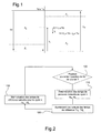
- the figure 1 is a diagram representing the principle of determining the position of a moving element by a time parameter of displacement from one of its end positions.
- the figure 2 is a flowchart describing the principle of calculating a displacement time information of the movable element between its two end-of-travel positions according to an embodiment of the method according to the invention.
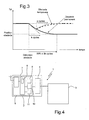
- the figure 3 is a diagram representing the effects in time, on the information of the duration of movement of the screen between its end positions, of the existence of a new breakpoint of the element, this new point stop being permanent or temporary.
- the figure 4 is a diagram of an installation according to the invention.
- the figure 1 shows schematically a home automation system 1 comprising an electromechanical actuator 2 for driving in motion a movable element 3 closing, occultation, sun protection or screen.
- This element may consist for example of a blind, a shutter, a window or a door.
- the movable element is intended to be operated between two end positions represented by stops.
- This movable element is driven in motion via the electromechanical actuator comprising on the one hand a motor assembly 4 and an electronic control unit 5 of the movement.
- the electronic control unit comprises communication means 6 for receiving motion control commands.
- the electronic unit further comprises a logic processing unit 7 comprising averaging means 8 and software means for governing the operation of the actuator and in particular governing its operation according to the method described below.
- the software means may include computer programs.
- the means for implementing the method comprise means for measuring time, in particular means for measuring the activation time of the actuator.
- the electronic unit comprises a time counter 9 measuring travel times of the movable element and electronic means for defining the current position of the movable element from the last position and the last travel time.
- Memories 10 are provided for recording the measured values and calculated by the electronic unit.
- the electronic unit also comprises a sensor 11 capable of detecting the arrival of the movable element in the end-of-travel positions (on a stop) or on an obstacle. This sensor may be a torque or torque variation detector, a sub-speed detection sensor or any other sensor known in the state of the art.
- the obstacle detection can be implemented either by a load relief detection (for example, the shutter blades stack up). or the load bar comes into contact with the obstacle), or by detecting a stress at winding.
- a load relief detection for example, the shutter blades stack up.
- the load bar comes into contact with the obstacle
- detecting a stress at winding This will be the case in particular for roller shutters: when the final blade is blocked on an obstacle to the descent, the motor continues to turn and unroll the screen in the shutter box. After a while, the flap gets stuck in the box and blocks the winding axis, which can be detected by the electronic unit. Instead, we talk about screen protection rather than obstacle detection, but in the description that follows, all these cases will be included in the obstacle detection.
- the positional time detection is active.
- the position of the obstacle in time will therefore not correspond to the physical position of the obstacle on the course of the screen, especially the descent.
- an obstacle of the gel or snow type retaining the final blade of a flap will be detected by recognition of a constraint to the winding.
- the position of the obstacle will be marked relatively accurately by the time counter.
- the sensor of the electronic unit is capable of operating with several different sensitivities.
- Time-based position management eliminates the need for a physical position sensor while managing positions and maneuvering areas, especially berthing areas.
- the electronic unit controls the motor until it detects a stop or an obstacle, but it also takes into account maneuvering times.
- a reference time corresponding to the travel time from one of the end-of-travel positions to the other end-of-travel position is defined.
- a rising reference time Tu and a reference time Td are defined.
- the reference time is used in particular for determining an arrival in a docking area.
- the invention allows a permanent update, or at least very frequently, reference times.
- the figure 1 shows the distinct areas in which the sensitivity of the obstacle detection and stop sensor is optimized.
- the areas close to the end positions Z1 and Z3 are called docking zones.
- Zone Z2 is the normal operating zone.
- the sensitivity of the sensor is increased, which causes a stop faster implemented on the stops of the end positions.
- the power of the actuator is reduced in the docking area.
- These docking zones are defined by a fixed travel time (for example 1 second of displacement of the movable element before arrival in one of the end-of-travel positions).
- the electronic unit manages this information of the sensor as follows:
- an obstacle or a stop detected is considered as a limit switch.
- the electronic unit will then determine a new reference time, based on a travel time between the first end position and this new position.
- the new reference time is defined using a weighted digital processing as provided in the invention.
- An end position marked by an obstacle or stop detected before arrival in the berthing zone is considered as the position of an obstacle. It is chosen that the electronic unit readjust the reference time to this obstacle, but does not readjust the next reference time from this obstacle, even if the path ends in the docking zone. During the next course to the obstacle, even if it is permanent (if it is a stop), the value of the reference time recorded tends to adjust itself to this new threshold .
- the value of the reference time readjusted previously will return quickly to its level preceding the obstacle detection.
- the figure 1 schematizes a frame for moving the movable element between a low end position FDCB corresponding to a position counter set to 0 and a high end position position FDCH corresponding to a position value at Td x Tu, Td and You are the reference time values between two end-of-travel positions, respectively downhill and upward, calculated according to the invention.
- Using a time product as a position indicator in the same meter greatly simplifies management by a microcontroller, in which the divisions are delicate.
- Td is the reference time downhill.
- a division by the product Tu x Td would give the corresponding positions X 'or Y' on a unit displacement scale, but it is preferable to use a product type scale.
- the operating method of the actuator 2 comprises several phases comprising in particular an initialization phase, an operating phase and a reset phase.
- the initialization phase is implemented automatically when a so-called "blank" actuator is installed and started for the first time.
- the memories are then blank and the actuator allows the screen to move between the end positions with certain precautions by default and while measuring a number of parameters that may be useful for the configuration thereof.
- This phase is transparent to the user, that is to say that it controls the movement of movement of the screen without knowing what phase of the process is implemented.
- the first x cycles can be used to determine, among other things, the reference times.
- the electronic unit measures, during the first x cycles, the maximum travel times between the end positions. These maximum travel times then become the reference times. Berthing areas are also determined during or following this phase.
- a procedure for determining the direction of rotation can be implemented. Indeed, according to the direction of assembly of the actuator, the rise or the descent can correspond to a first or a second direction of rotation. This procedure may be as described in the patent EP 0 833 435 .
- the behavior of the actuator in particular for the detection of abutment or obstacle can be defined asymmetrically depending on the upward direction or the downward direction determined, for example a first detection sensitivity is assigned to the rise and a second detection sensitivity is assigned to the descent.
- a number x 'of cycles is dedicated to this determination procedure, during which the behavior of the actuator is symmetrical for both directions of rotation.
- the x 'rotation direction determination cycles may be at least partly merged with the x cycles for the determination of the reference times.
- the actuator retains its behavior symmetrical.
- a so-called continuous adjustment, automatic or self-adjusting operation mode is implemented during the following cycles.
- This self-adjustment is based on a readjustment of the reference times, implemented as soon as a detection of end position or possibly obstacle occurs.
- the figure 2 shows in the form of a flow chart, the calculations of the new travel times serving as a reference.
- a first step 100 it is tested whether one has left an end position for performing a recalculation of the average duration of extreme displacement of the movable element. If this is not the case, we will loop on this test. On the other hand, if this is the case, we go to a step 110, in which we determine the new measured value of travel time, denoted td n downwards or n upwards.
- this new travel time value is used as follows to calculate the new value of the reference time in climb Tu n or the reference time in descent Td n .
- a reference time is thus updated automatically after each cycle.
- k it is possible to vary k depending on the type of detection: to correct a simple drift with respect to the previously determined end positions, that is to say for example if the differences between the times calculated and measured are small or when detecting the end position in a docking area, the weighted average can be performed over approximately 5 cycles.
- this obstacle is encountered once, it has disappeared before the next maneuver cycle, or on the contrary, that the obstacle is said to be permanent (this will be the case for example if a new floor screed is made after the installation of this screen or if an installer reinstalls the actuator with a new screen for another window for example).
- the initialization of the algorithm preferably consists of an assignment of the first reference time value determined during the initialization mode as the average of the reference times of the preceding cycles.
- the electronic unit determines a real running average over a predetermined number of cycles of operation.
- the weighting is equal to 1 for the k 'last values and equal to 0 for the previous cycles.
- the actual sliding average then takes into account only the last k 'cycles. This is effectively fully active after the k 'cycles of operation, even if the preceding equations can be used for readjustments on k' first cycles. Only these are then integrated into the calculation.
- the initialization of the algorithm consists of an assignment of the first measured value to all the stored values.
- the figure 3 graphically illustrates the readjustment over time by weighted averages, the value of the reference time in descent when a permanent obstacle occurs on a cycle (bold line curve) and at the time of occurrence a temporary obstacle (dotted line).
- the reference time is readjusted (that is to say that 95% of the difference between the two parallel horizontal lines is reached) after 3.k cycles for a weighted average .
- One advantage is to keep an "offset" docking zone in relation to the reference time, when the docking area is defined by the formula comprising the subtraction of a fixed parameter from the reference time.
- the docking zones it is possible to define for the docking zones a fixed time or relative to the last reference time in memory and depending on the difference between the last measured travel times, if it is positive.
- the docking zone is itself readjusted so that the obstacle zone is included in a berthing area.
- This readjustment of the docking area may be provided only in a direction of rotation, for example for descent, in order to avoid, given the higher detection sensitivity of not being able to pass torque peaks when the actuator must lift the moving element uphill.
- the arrival on the obstacle will be carried out with a lower sensitivity (because the broom is located outside the berthing area).
- the reference time is readjusted from the value Td n-1 to the value Td n accordingly, according to the invention by the principle of means.
- ⁇ 5.
- the arrival on the obstacle zone will then be placed in an area of increased sensitivity.
- the docking area will be redefined to its original value.
- the docking zone in the following cycle retains the value relative to the last measured extreme travel time.
- the nominal value of the docking area may be a fixed value, including in this embodiment.
- its value also adjusts smoothly following the adjustment of the reference time.
- the actuator sets up ultimate travel time or security. This takes a fixed initial value, then self-adjusts according to the reference times by adding a fixed value, for example 20 seconds, to the last calculated reference times.
- This reset by the installer requires to provide a specific input interface or ergonomics to interact with the electronic unit of the actuator and indicate the willingness of the installer to return the actuator in a blank state.
- These use cases are for example cases of reuse of an actuator for a different product (for example from a roller shutter to a blind), in a different frame (window to cover of different size), or simple assembly of the actuator in a different sense.
- a situation of repeated and consecutive detection of obstacles outside the docking zones in both directions of rotation can for example be observed.
- This situation corresponds for example to the repositioning of an actuator to a flap for small window size, that is to say such that the extreme travel times are lower than the reference travel times less the time allocated for the docking areas.
- This is a situation in which the conditions of use of the actuator have changed radically but in which the use remains possible.
- This resetting procedure makes it possible to place the actuator in a blank mode equivalent to an actuator at its manufacturing output and to resume the calculations of the reference times to zero by no longer taking into account the previous values. According to one aspect of the invention, it is implemented automatically following repeated detection of obstacles that do not lead to self-adjustment.
- the registration procedure according to the invention makes it possible to automatically place the actuator in a blank mode equivalent to an actuator at its manufacturing output and to restart the determinations of the rotational directions by no longer taking into account the previous values. . It is also implemented if after a certain number of cycles with self-adjustment, the difference between the up and down reference times becomes insignificant when it was before. Alternatively, only the determination part of the direction of rotation is reiterated, the reference times adjusting during the phases of operation in self-adjustment.
- the electronic unit notes in this case, during the self-adjustment, that the values of the reference times converge to a common value. When the difference between these reference times is no longer significant, either following a number of cycles having such a convergence, the electronic unit decides to update its operating parameters and reiterates the initialization phase.
- the term "cycle” the set of displacements preferentially in the same direction of the movable element from an abutment position or a starting position located in a docking zone to another abutment position or to an obstacle.
- the method according to the invention makes it possible to obtain information of travel time between end-stops that is sufficiently precise to be able to manage, thanks to this information, an intermediate position between the end-of-travel positions of the mobile element.
- an intermediate position datum for example a percentage
- the duration to reach, from one of the end positions, this intermediate position can be defined as the product of the percentage and the information of travel time.
- a detailed example of such a management is for example described in lines 29 to 37 of column 5 of the document EP 0 574 637 .
Description
L'invention concerne le domaine des motorisations d'éléments mobiles de fermeture, d'occultation, de protection solaire ou d'écran dans un bâtiment, l'élément mobile se déplaçant entre une première position de fin de course et une deuxième position de fin de course, ces déplacements étant provoqués par des mouvements de rotation du moteur.The invention relates to the field of motorization of mobile elements closing, concealment, sun protection or screen in a building, the movable element moving between a first end position and a second end position stroke, these displacements being caused by rotational movements of the engine.
Il est courant de disposer des volets roulants ou des stores au niveau des ouvertures des habitations, ayant des fonctions de protection solaire, d'assombrissement ou de sécurité contre les intrusions. Ces éléments mobiles sont pilotés automatiquement grâce à des actionneurs alimentés par le réseau ou autonomes.It is common to have roller shutters or blinds at home openings that have sun protection, darkening or intrusion safety features. These mobile elements are controlled automatically thanks to actuators powered by the network or autonomous.
L'installation et le contrôle du mouvement de ces éléments mobiles sont assez complexes et requièrent les services d'une personne qualifiée.The installation and movement control of these moving parts is quite complex and requires the services of a qualified person.
Les procédures d'installation visent généralement à définir et éventuellement à mémoriser les première et deuxième positions de fin de course au niveau desquelles l'élément mobile doit, en fonctionnement, automatiquement arrêter sa course, ainsi que diverses positions ou paramètres de fonctionnement.The installation procedures are generally intended to define and possibly memorize the first and second end positions at which the mobile element must, in operation, automatically stop its stroke, as well as various positions or operating parameters.
De telles procédures d'installation sont largement décrites dans l'art antérieur. Il existe en général un mode dit mode d'apprentissage au cours duquel l'élément mobile est déplacé jusqu'à ces positions de fin de course ou positions extrêmes, qui sont alors enregistrées, soit manuellement soit automatiquement.Such installation procedures are widely described in the prior art. There is generally a mode called learning mode in which the movable element is moved to these end positions or extreme positions, which are then recorded, either manually or automatically.
Plus récemment, divers brevets et demandes de brevet décrivent des procédés d'installation dans lequel l'installateur n'intervient pas ou très peu.More recently, various patents and patent applications describe methods of installation in which the installer does not intervene or very little.
Ainsi la demande
Dans le même domaine, le brevet
Des procédures de recalage régulières (tous les 100 cycles) sont prévues, de façon à écarter tout risque de dérive dans le cas d'une erreur de comptage (due par exemple à un pic de tension). Dans ce cas, le compteur est remis à jour au niveau d'une butée. Ce recalage régulier n'est en aucun cas lié à une inadéquation de l'auto-ajustement vis à vis des changements de fonctionnement rencontrés.Regular registration procedures (every 100 cycles) are planned, so as to avoid any risk of drift in the case of a counting error (due for example to a peak voltage). In this case, the counter is updated at a stop. This regular registration is in no way related to a mismatch of the self-adjustment vis-à-vis the operating changes encountered.
Le procédé d'ajustement automatique décrit dans ce brevet est applicable uniquement à une installation disposant d'un système de comptage précis et sûr.The automatic adjustment method described in this patent is applicable only to an installation having a precise and safe counting system.
Si on souhaite s'affranchir d'un compteur de position, il existe différentes méthodes pour repérer une position et notamment par repérage temporel. Une telle méthode est décrite par exemple dans les demandes de brevet
En particulier, la demande
Dans les deux cas, l'installateur met en oeuvre préalablement au fonctionnement en mode dit d'usage, une procédure d'installation dans laquelle il déplace l'élément mobile d'une position quelconque vers une première position de butée, puis vers une deuxième en mesurant un premier temps de parcours et enfin, il déplace l'élément mobile vers la première position de butée en mesurant un deuxième temps de parcours. Une fois ainsi configurée, l'installation est opérationnelle. Ces déplacements peuvent également avoir lieu de manière automatique à l'entrée dans un mode d'installation. Les temps de parcours ainsi mesurés font cependant office de référence pour toute la durée de vie du produit.In both cases, the installer implements, prior to the so-called use mode operation, an installation procedure in which he moves the movable element from any position to a desired position. first stop position, then to a second by measuring a first travel time and finally, he moves the movable member to the first stop position by measuring a second travel time. Once configured, the installation is operational. These movements can also take place automatically when entering an installation mode. The measured travel times, however, serve as a reference for the entire lifetime of the product.
Le but de l'invention est de fournir une alternative aux procédés décrits, qui permette de configurer très simplement une installation d'écran motorisée, de manière automatique et qui permette également de s'adapter aux diverses situations de fonctionnement changeantes. De plus, l'invention permet de remettre à jour des paramètres a priori fixés lors de l'installation, sans intervention de l'installateur. L'invention permet donc d'obtenir un véritable actionneur "Plug and Play", capable de s'auto-configurer quelle que soit sa configuration d'origine, quelles que soient les conditions de fonctionnement pour lesquelles il est installé ou réinstallé, et même dans le cas où ces conditions sont modifiées radicalement.The object of the invention is to provide an alternative to the methods described, which makes it possible to very simply configure a motorized screen installation, automatically and which also makes it possible to adapt to various changing operating situations. In addition, the invention makes it possible to update parameters a priori fixed during installation, without intervention of the installer. The invention thus makes it possible to obtain a true "Plug and Play" actuator, capable of self-configuration regardless of its original configuration, whatever the operating conditions for which it is installed or reinstalled, and even in the event that these conditions are radically changed.
Le procédé de fonctionnement selon l'invention est défini par la revendication 1.The operating method according to the invention is defined by
Différents modes d'exécution sont définis par les revendications dépendantes 2 à 12.Different embodiments are defined by dependent claims 2 to 12.
L'installation selon l'invention est définie par la revendication 13.The plant according to the invention is defined by claim 13.
Différents modes de réalisation de l'installation sont définis par les revendications dépendantes 14 et 15.Different embodiments of the installation are defined by the dependent claims 14 and 15.
Le dessin annexé représente, à titre d'exemple, un mode de réalisation d'une installation selon l'invention et le principe d'un mode d'exécution du procédé de fonctionnement selon l'invention.The attached drawing shows, by way of example, an embodiment of an installation according to the invention and the principle of an embodiment of the operating method according to the invention.
La
La
La
La
La
L'élément mobile est destiné à être manoeuvré entre deux positions de fin de course matérialisées par des butées. Cet élément mobile est entraîné en mouvement par l'intermédiaire de l'actionneur électromécanique comprenant d'une part un ensemble moteur 4 et une unité électronique 5 de commande du mouvement.The movable element is intended to be operated between two end positions represented by stops. This movable element is driven in motion via the electromechanical actuator comprising on the one hand a
L'unité électronique de commande comprend des moyens 6 de communication pour recevoir des ordres de commande de mouvement. L'unité électronique comprend en outre une unité logique de traitement 7 comprenant des moyens 8 de calcul de moyenne et des moyens logiciels pour régir le fonctionnement de l'actionneur et notamment régir son fonctionnement selon le procédé qui est décrit plus bas. Les moyens logiciels peuvent notamment comprendre des programmes informatiques. Les moyens de mise en oeuvre du procédé comprennent des moyens de mesure de temps, en particulier des moyens de mesure du temps d'activation de l'actionneur.The electronic control unit comprises communication means 6 for receiving motion control commands. The electronic unit further comprises a
L'unité électronique comprend un compteur temporel 9 mesurant des temps de parcours de l'élément mobile et des moyens électroniques pour définir la position courante de l'élément mobile à partir de la dernière position et du dernier temps de parcours. Des mémoires 10 sont prévues pour l'enregistrement des valeurs mesurées et calculées par l'unité électronique. L'unité électronique comprend également un capteur 11 capable de détecter l'arrivée de l'élément mobile dans les positions de fin de course (sur une butée) ou sur un obstacle. Ce capteur peut être un détecteur de couple ou de variation de couple, un capteur de détection de sous-vitesse ou tout autre capteur connu dans l'état de l'art.The electronic unit comprises a
Pour des écrans lourds mais non rigides, par exemple des volets roulants ou stores à barre de charge lestée, la détection d'obstacle pourra être mise en oeuvre soit par une détection d'allègement de charge (les lames de volets s'empilent par exemple ou la barre de charge arrive en contact sur l'obstacle), soit par détection d'une contrainte à l'enroulement. Ce sera le cas notamment des volets roulants : lorsque la lame finale est bloquée sur un obstacle à la descente, le moteur continue à tourner et à dérouler l'écran dans le caisson de volet. Au bout d'un certain temps, le volet se coince dans le caisson et bloque l'axe d'enroulement, ce qui peut être détecté par l'unité électronique. On parle alors plutôt de protection de l'écran plutôt que de détection d'obstacle, mais dans la description qui va suivre, tous ces cas seront compris dans la détection d'obstacle.For heavy but non-rigid screens, for example rolling shutters or weighted load bar blinds, the obstacle detection can be implemented either by a load relief detection (for example, the shutter blades stack up). or the load bar comes into contact with the obstacle), or by detecting a stress at winding. This will be the case in particular for roller shutters: when the final blade is blocked on an obstacle to the descent, the motor continues to turn and unroll the screen in the shutter box. After a while, the flap gets stuck in the box and blocks the winding axis, which can be detected by the electronic unit. Instead, we talk about screen protection rather than obstacle detection, but in the description that follows, all these cases will be included in the obstacle detection.
Il est à noter que lors du déroulement du volet dans le caisson et tant que le moteur continue de tourner, la détection temporelle de position est active. La position de l'obstacle en temporel ne correspondra donc pas à la position physique de l'obstacle sur la course de l'écran, en particulier à la descente.It should be noted that during the unwinding of the shutter in the box and as the engine continues to rotate, the positional time detection is active. The position of the obstacle in time will therefore not correspond to the physical position of the obstacle on the course of the screen, especially the descent.
A la montée, un obstacle du type gel ou neige retenant la lame finale d'un volet sera détecté par reconnaissance d'une contrainte à l'enroulement. La position de l'obstacle sera repérée de manière relativement précise par le compteur temporel.At the climb, an obstacle of the gel or snow type retaining the final blade of a flap will be detected by recognition of a constraint to the winding. The position of the obstacle will be marked relatively accurately by the time counter.
Avantageusement, le capteur de l'unité électronique est capable de fonctionner avec plusieurs sensibilités différentes.Advantageously, the sensor of the electronic unit is capable of operating with several different sensitivities.
Dans le cas d'un système tout automatique où seule une détection de butée est active (sans détection de position), il n'est pas possible de gérer des zones dites d'accostage dans lesquels une arrivée en butée est réalisée de manière plus douce, soit par une sensibilité de détection accrue ou une vitesse d'accostage plus faible (la butée est alors détectée très tôt et la contrainte sur l'écran est moindre) ou une force appliquée plus faible. Dans ce cas, la puissance de l'actionneur est réduite.In the case of a fully automatic system where only a stop detection is active (without position detection), it is not possible to manage so-called docking zones in which an end stop is performed in a gentler manner. either by increased detection sensitivity or a lower docking speed (the stop is then detected very early and the stress on the screen is lower) or a lower applied force. In this case, the power of the actuator is reduced.
La gestion des positions par mesures temporelles permet de s'affranchir d'un capteur de position physique tout en gérant des positions et des zones de manoeuvre, en particulier des zones d'accostage. En fonctionnement normal, l'unité électronique pilote le moteur jusqu'à ce qu'elle détecte une butée ou un obstacle, mais elle tient également compte des temps de manoeuvre.Time-based position management eliminates the need for a physical position sensor while managing positions and maneuvering areas, especially berthing areas. In normal operation, the electronic unit controls the motor until it detects a stop or an obstacle, but it also takes into account maneuvering times.
Comme dans l'art antérieur, on définit un temps de référence correspondant à la durée de parcours depuis l'une des positions de fin de course vers l'autre position de fin de course. Avantageusement, un temps de référence en montée Tu et un temps de référence en descente Td sont définis. Le temps de référence est utilisé en particulier pour la détermination d'une arrivée dans une zone d'accostage. L'invention permet une mise à jour permanente, ou au moins très fréquente, des temps de référence.As in the prior art, a reference time corresponding to the travel time from one of the end-of-travel positions to the other end-of-travel position is defined. Advantageously, a rising reference time Tu and a reference time Td are defined. The reference time is used in particular for determining an arrival in a docking area. The invention allows a permanent update, or at least very frequently, reference times.
La
Ces zones d'accostage sont définies par un temps de parcours fixe (par exemple 1 seconde de déplacement de l'élément mobile avant l'arrivée dans l'une des positions de fin de course).These docking zones are defined by a fixed travel time (for example 1 second of displacement of the movable element before arrival in one of the end-of-travel positions).
Lors d'une arrivée dans une position dans laquelle le capteur détecte une butée, l'unité électronique gère cette information du capteur de la manière suivante :When an arrival in a position in which the sensor detects a stop, the electronic unit manages this information of the sensor as follows:
Dans la zone d'accostage, un obstacle ou une butée détectée est considéré comme une fin de course. L'unité électronique va alors déterminer un nouveau temps de référence, basé sur un temps de parcours entre la première position de fin de course et cette nouvelle position. Le nouveau temps de référence est défini en utilisant un traitement numérique pondéré comme prévu dans l'invention.In the docking area, an obstacle or a stop detected is considered as a limit switch. The electronic unit will then determine a new reference time, based on a travel time between the first end position and this new position. The new reference time is defined using a weighted digital processing as provided in the invention.
Une position de fin de course matérialisée par un obstacle ou une butée détectée avant l'arrivée dans la zone d'accostage est considérée comme la position d'un obstacle. On choisit que l'unité électronique réajuste le temps de référence vers cet obstacle, mais ne réajuste pas le temps de référence suivant à partir de cet obstacle, même si le parcours se termine dans la zone d'accostage. Lors du parcours suivant vers l'obstacle, même si celui-ci est permanent (s'il s'agit d'une butée), la valeur du temps de référence enregistré tend à s'ajuster d'elle-même à ce nouveau seuil.An end position marked by an obstacle or stop detected before arrival in the berthing zone is considered as the position of an obstacle. It is chosen that the electronic unit readjust the reference time to this obstacle, but does not readjust the next reference time from this obstacle, even if the path ends in the docking zone. During the next course to the obstacle, even if it is permanent (if it is a stop), the value of the reference time recorded tends to adjust itself to this new threshold .
Si l'obstacle est temporaire, la valeur du temps de référence réajustée précédemment reviendra rapidement à son niveau précédant la détection d'obstacle.If the obstacle is temporary, the value of the reference time readjusted previously will return quickly to its level preceding the obstacle detection.
La différentiation entre butée et obstacle permet de gérer différemment les calculs de moyennes comme expliqué plus loin.The differentiation between abutment and obstacle makes it possible to manage differently the averages calculations as explained below.
Lorsqu'un obstacle est placé sur le parcours du volet en descente, par exemple une chaise ou un pot de fleur, alors que le volet continue d'être actionné, par exemple par un automatisme piloté par horloge, une mise à jour trop rapide des temps de référence n'est pas nécessairement souhaitée, vu qu'il ne s'agit pas d'un obstacle permanent. Le temps de référence en montée, partant d'un obstacle, n'est pas modifié. Seul le temps de référence en descente est réajusté dans un tel cas, la fin de course haute pouvant dans ce cas toujours être dans la zone d'accostage. Si cette situation se poursuit, la zone d'accostage basse finit par englober l'obstacle. Les temps de référence en montée et en descente peuvent alors être tous les deux réajustés conformément à l'invention.When an obstacle is placed on the path of the downward flap, for example a chair or a flower pot, while the shutter continues to be actuated, for example by a clock-controlled automatism, an update too fast of Reference time is not necessarily desirable, as it is not a permanent obstacle. The reference time uphill, starting from an obstacle, is not modified. Only the reference time downhill is readjusted in such a case, the end of high race may in this case still be in the docking area. If this situation continues, the low berthing area eventually encompasses the obstacle. Both up and down reference times can be readjusted according to the invention.
La
Les positions de l'écran entre les positions de fin de course peuvent aussi être repérées simplement comme explicité dans la demande
On suppose que, depuis la position basse, l'écran est manoeuvré jusqu'à une position X. Cette position est repérée par l'unité de commande par le temps de parcours réalisé t1 depuis la position de fin de course inférieure multiplié par le temps de référence en montée Tu.It is assumed that, from the low position, the screen is maneuvered to a position X. This position is indicated by the control unit by the travel time realized t 1 from the lower end position multiplied by the reference time uphill Tu.
Depuis la position X, une nouvelle position Y est atteinte par un déplacement vers le bas d'une durée t2, celle-ci est repérée par l'équation suivante ![]()
dans laquelle Td est le temps de référence en descente. Une division par le produit Tu x Td donnerait les positions correspondantes X' ou Y' sur une échelle de déplacement unitaire, mais il est préférable d'utiliser une échelle de type produit.From position X, a new position Y is reached by a downward movement of a duration t 2 , which is indicated by the following equation ![]()
where Td is the reference time downhill. A division by the product Tu x Td would give the corresponding positions X 'or Y' on a unit displacement scale, but it is preferable to use a product type scale.
Le procédé de fonctionnement de l'actionneur 2 comprend plusieurs phases comprenant notamment une phase d'initialisation, une phase de fonctionnement et une phase de remise à zéro.The operating method of the actuator 2 comprises several phases comprising in particular an initialization phase, an operating phase and a reset phase.
La phase d'initialisation est mise en oeuvre automatiquement lorsqu'un actionneur dit "vierge" est installé et démarré pour la première fois. Les mémoires sont alors vierges et l'actionneur permet à l'écran de se déplacer entre les positions de fin de course avec certaines précautions par défaut et tout en mesurant un certain nombre de paramètres pouvant être utiles pour la configuration de celui-ci. Cette phase est transparente pour l'utilisateur, c'est-à-dire que celui-ci commande les mouvements de déplacement de l'écran sans savoir quelle phase du procédé est mise en oeuvre.The initialization phase is implemented automatically when a so-called "blank" actuator is installed and started for the first time. The memories are then blank and the actuator allows the screen to move between the end positions with certain precautions by default and while measuring a number of parameters that may be useful for the configuration thereof. This phase is transparent to the user, that is to say that it controls the movement of movement of the screen without knowing what phase of the process is implemented.
Pour l'initialisation des données de fonctionnement, les x premiers cycles peuvent être utilisés pour déterminer entre autres les temps de référence. L'unité électronique mesure alors, durant les x premiers cycles les temps de parcours maximum entre les positions de fin de course. Ces temps de parcours maximum deviennent alors les temps de référence. Les zones d'accostage sont également déterminées au cours ou suite à cette phase.For the initialization of the operating data, the first x cycles can be used to determine, among other things, the reference times. The electronic unit then measures, during the first x cycles, the maximum travel times between the end positions. These maximum travel times then become the reference times. Berthing areas are also determined during or following this phase.
Suite à ces x premiers cycles, une procédure de détermination du sens de rotation peut être mise en oeuvre. En effet, selon le sens de montage de l'actionneur, la montée ou la descente peut correspondre à un premier ou un deuxième sens de rotation. Cette procédure peut être telle que décrite dans le brevet
Ainsi, le comportement de l'actionneur, notamment pour la détection de butée ou d'obstacle peut être défini de manière asymétrique en fonction du sens montée ou du sens descente déterminé, par exemple une première sensibilité de détection est assignée à la montée et une deuxième sensibilité de détection est assignée à la descente.Thus, the behavior of the actuator, in particular for the detection of abutment or obstacle can be defined asymmetrically depending on the upward direction or the downward direction determined, for example a first detection sensitivity is assigned to the rise and a second detection sensitivity is assigned to the descent.
Un certain nombre x' de cycles est dédié à cette procédure de détermination, au cours desquels le comportement de l'actionneur est symétrique pour les deux sens de rotation.A number x 'of cycles is dedicated to this determination procedure, during which the behavior of the actuator is symmetrical for both directions of rotation.
Les x' cycles de détermination du sens de rotation peuvent être confondus, au moins en partie, avec les x cycles pour la détermination des temps de référence.The x 'rotation direction determination cycles may be at least partly merged with the x cycles for the determination of the reference times.
Si le sens de rotation ne peut être déterminé par la procédure de détermination décrite ci-dessus, soit parce que par exemple la différence entre le temps de montée et le temps de descente du volet n'est pas significative, l'actionneur conserve son comportement symétrique.If the direction of rotation can not be determined by the determination procedure described above, either because for example the difference between the rise time and the flap descent time is not significant, the actuator retains its behavior symmetrical.
Suite au mode d'initialisation, un mode de fonctionnement dit d'ajustement continu, ou automatique ou d'auto-ajustement, est mis en oeuvre lors des cycles suivants. Cet auto-ajustement est basé sur un réajustement des temps de référence, mis en oeuvre dès qu'une détection de position de fin de course ou éventuellement d'obstacle intervient.Following the initialization mode, a so-called continuous adjustment, automatic or self-adjusting operation mode is implemented during the following cycles. This self-adjustment is based on a readjustment of the reference times, implemented as soon as a detection of end position or possibly obstacle occurs.
La
Dans une première étape 100, on teste si l'on est parti d'une position de fin de course permettant d'effectuer un nouveau calcul de moyenne de durée de déplacement extrême de l'élément mobile. Si tel n'est pas le cas on boucle sur ce test. Par contre, si tel est le cas, on passe à une étape 110, dans laquelle on détermine la nouvelle valeur mesurée de temps de déplacement, notée tdn vers le bas ou tun vers le haut.In a
Dans une étape 120, on utilise cette nouvelle valeur de temps de déplacement comme suit pour calculer la nouvelle valeur du temps de référence en montée Tun ou du temps de référence en descente Tdn.In a
Dans un premier mode de réalisation, les temps de référence sont définis par une moyenne glissante fictive ou moyenne pondérée sur les k derniers cycles en affectant la moyenne Tun-1 ou Tdn-1 établie précédemment à l'ensemble des k-1 valeurs précédentes : ![]()
![]()
![]()
![]()
Ce traitement numérique est strictement équivalent à appliquer un filtrage numérique d'ordre 1 aux valeurs mesurées pour en déduire le nouveau temps de référence. En posant α = 1/k, on obtient les relations équivalentes : ![]()
![]()
![]()
![]()
Un temps de référence est ainsi remis à jour automatiquement après chaque cycle.A reference time is thus updated automatically after each cycle.
Il est possible de faire varier k en fonction du type de détection : pour corriger une simple dérive par rapport aux positions de fin de course précédemment déterminées, c'est-à-dire par exemple si les différences entre les temps calculés et mesurés sont petites ou lors de la détection de la position de fin de course dans une zone d'accostage, la moyenne pondérée peut être réalisée sur environ 5 cycles. Un tel filtrage (équivalent à α = 0,2) permet de converger assez rapidement vers une commande de position conforme à la réalité physique et donc d'ajouter à la performance de cette commande.It is possible to vary k depending on the type of detection: to correct a simple drift with respect to the previously determined end positions, that is to say for example if the differences between the times calculated and measured are small or when detecting the end position in a docking area, the weighted average can be performed over approximately 5 cycles. Such a filtering (equivalent to α = 0.2) makes it possible to converge rather quickly towards a position control that conforms to the physical reality and therefore to add to the performance of this command.
En revanche, si l'unité électronique détecte un obstacle sur le parcours en dehors d'une zone d'accostage, la moyenne pondérée peut être associée à un coefficient égal à 10 ou plus (α = 0,1). La convergence est alors plus lente mais la prise en compte de l'obstacle est également minimisée.On the other hand, if the electronic unit detects an obstacle on the course outside a docking area, the weighted average may be associated with a coefficient equal to 10 or more (α = 0.1). The convergence is then slower but the consideration of the obstacle is also minimized.
L'intérêt de ce filtrage est évidemment de prendre en compte mais de manière souple les différents événements rencontrés lors de la manoeuvre de l'élément mobile, sans apporter des réponses trop instantanées à ces évènements.The interest of this filtering is obviously to take into account but in a flexible way the different events encountered during the maneuver of the mobile element, without providing too instantaneous responses to these events.
En effet, lors d'une détection d'obstacle, il est possible que cet obstacle ne soit rencontré qu'une fois, celui-ci ayant disparu avant le cycle de manoeuvre suivant, ou au contraire, que l'obstacle soit dit permanent (ce sera le cas par exemple si une nouvelle chape au sol est réalisée après l'installation de cet écran ou si un installateur réinstalle l'actionneur avec un nouvel écran pour une autre fenêtre par exemple).Indeed, during an obstacle detection, it is possible that this obstacle is encountered once, it has disappeared before the next maneuver cycle, or on the contrary, that the obstacle is said to be permanent ( this will be the case for example if a new floor screed is made after the installation of this screen or if an installer reinstalls the actuator with a new screen for another window for example).
Dans la plupart des systèmes connus, il serait dans ce dernier cas nécessaire de prévoir une réinitialisation des positions de fonctionnement, avec par exemple un nouvel apprentissage des positions de fin de course. Au contraire, en utilisant un auto-ajustement de l'actionneur tout au long de la vie de l'installation, celui-ci se réajuste progressivement et prend en compte autant les modifications brutales que les changements uniquement perceptibles au cours du temps.In most known systems, in the latter case it would be necessary to provide for a reset of the positions of operation, for example with a new learning of the end positions. On the contrary, by using an auto-adjustment of the actuator throughout the life of the installation, it is readjusted gradually and takes into account both the sudden changes that changes only perceptible over time.
L'initialisation de l'algorithme consiste préférentiellement en une affectation de la première valeur de temps de référence déterminée lors du mode d'initialisation en tant que moyenne des temps de référence des cycles précédents.The initialization of the algorithm preferably consists of an assignment of the first reference time value determined during the initialization mode as the average of the reference times of the preceding cycles.
Dans un second mode de réalisation, plutôt qu'une moyenne pondérée, l'unité électronique détermine une moyenne glissante réelle sur un nombre k' prédéterminé de cycles de fonctionnement. La pondération est égale à 1 pour les k' dernières valeurs et égale à 0 pour les cycles antérieurs.In a second embodiment, rather than a weighted average, the electronic unit determines a real running average over a predetermined number of cycles of operation. The weighting is equal to 1 for the k 'last values and equal to 0 for the previous cycles.
Les k'-1 valeurs précédentes de temps de référence sont mémorisées et le temps de référence au cycle n est obtenu selon les formules suivantes : ![]()
![]()
![]()
![]()
La moyenne glissante réelle ne prend alors en compte que les k' derniers cycles. Celle-ci est effectivement complètement active au bout des k' cycles de fonctionnement, même si les équations précédentes peuvent être utilisées pour les réajustements sur les k' premiers cycles. Seuls ceux-ci sont alors intégrés dans le calcul. L'initialisation de l'algorithme consiste en une affectation de la première valeur mesurée à toutes les valeurs mémorisées.The actual sliding average then takes into account only the last k 'cycles. This is effectively fully active after the k 'cycles of operation, even if the preceding equations can be used for readjustments on k' first cycles. Only these are then integrated into the calculation. The initialization of the algorithm consists of an assignment of the first measured value to all the stored values.
La
En effet, avec un filtrage numérique de premier ordre caractérisé par α, la tangente à l'origine (point de rupture de pente de la courbe) coupe la valeur finale au bout de 1/α = k cycles ou échantillons. C'est la constante de temps. On dépasse 95% de l'écart entre les valeurs initiale et finale au bout de 3 constantes de temps, et 99% de l'écart entre les valeurs initiale et finale au bout de 5 constantes de temps.Indeed, with a first-order digital filtering characterized by α, the tangent at the origin (slope breaking point of the curve) cuts the final value after 1 / α = k cycles or samples. It's the time constant. Exceeding 95% of the difference between the initial and final values after 3 time constants, and 99% of the difference between the initial and final values after 5 time constants.
Un avantage est de conserver une zone d'accostage "décalée" en lien avec le temps de référence, lorsque la zone d'accostage est définie de par formule comprenant la soustraction d'un paramètre fixe au temps de référence.One advantage is to keep an "offset" docking zone in relation to the reference time, when the docking area is defined by the formula comprising the subtraction of a fixed parameter from the reference time.
Alternativement, il est possible de définir pour les zones d'accostage un temps fixe ou relatif au dernier temps de référence en mémoire et dépendant de la différence entre les derniers temps de parcours mesurés, si celle-ci est positive. Ainsi, lors de la mesure d'un temps de parcours extrême très différent de la mesure du temps de parcours extrême au cycle précédent, la zone d'accostage est elle-même réajustée fortement de sorte que la zone d'obstacle soit comprise dans une zone d'accostage. Ce réajustement de la zone d'accostage peut n'être prévu que dans un sens de rotation, par exemple pour la descente, afin d'éviter, compte tenu de la sensibilité plus élevée de détection de ne pouvoir passer des pics de couple lorsque l'actionneur doit soulever l'élément mobile en montée.Alternatively, it is possible to define for the docking zones a fixed time or relative to the last reference time in memory and depending on the difference between the last measured travel times, if it is positive. Thus, when measuring an extreme journey time that is very different from the measurement of the extreme travel time in the previous cycle, the docking zone is itself readjusted so that the obstacle zone is included in a berthing area. This readjustment of the docking area may be provided only in a direction of rotation, for example for descent, in order to avoid, given the higher detection sensitivity of not being able to pass torque peaks when the actuator must lift the moving element uphill.
En effet, dans le cas d'un obstacle temporaire détecté au cycle n, par exemple un balai bloquant le déroulement du tablier d'un volet roulant, l'arrivée sur l'obstacle sera réalisée avec une sensibilité plus faible (car le balai se situe hors zone d'accostage). Le temps de référence est réajusté de la valeur Tdn-1 à la valeur Tdn en conséquence, conformément à l'invention par le principe de moyennes. La durée spécifique Z1 définissant la zone d'accostageZ1 est alors calculée à partir de l'équation suivante : ![]()
![]()
![]()
![]()
L'arrivée sur la zone d'obstacle sera alors placée dans une zone de sensibilité accrue.The arrival on the obstacle zone will then be placed in an area of increased sensitivity.
Si l'obstacle a été enlevé, au prochain parcours, la différence entre le temps de parcours extrême venant d'être mesuré et le temps de parcours extrême du cycle précédent étant négative, la zone d'accostage sera redéfinie à sa valeur première.If the obstacle has been removed, at the next course, the difference between the extreme travel time just measured and the extreme travel time of the previous cycle being negative, the docking area will be redefined to its original value.
Si en revanche, il s'agit d'un obstacle de type permanent, la zone d'accostage dans le cycle suivant conserve la valeur relative au dernier temps de parcours extrême mesuré.If, on the other hand, it is a permanent type of obstacle, the docking zone in the following cycle retains the value relative to the last measured extreme travel time.
Comme dit précédemment, la valeur nominale de la zone d'accostage peut être une valeur fixe, y compris dans ce mode de réalisation. En revanche, si elle est relative au temps de référence défini par l'unité électronique, sa valeur s'ajuste également de manière douce en suivant l'ajustement du temps de référence.As previously stated, the nominal value of the docking area may be a fixed value, including in this embodiment. On the other hand, if it relates to the reference time defined by the unit electronic, its value also adjusts smoothly following the adjustment of the reference time.
Pour sécuriser de plus le fonctionnement de l'actionneur, on met en place un temps de parcours ultime ou de sécurité. Celui-ci prend une valeur initiale fixe, puis s'auto-ajuste conformément aux temps de référence en ajoutant une valeur fixe, par exemple 20 secondes, aux derniers temps de référence calculés.To further secure the operation of the actuator, it sets up ultimate travel time or security. This takes a fixed initial value, then self-adjusts according to the reference times by adding a fixed value, for example 20 seconds, to the last calculated reference times.
En dehors du fonctionnement classique dans lequel l'actionneur est soumis à de légères dérives, celles-ci étant prises en compte par l'auto-ajustement, certains cas particuliers d'utilisation peuvent survenir provoquant des changements plus importants. Ces changements, en dehors de l'invention, doivent généralement nécessiter une intervention d'installateur, par exemple par une procédure de remise à zéro des paramètres de fonctionnement appris.Apart from the conventional operation in which the actuator is subjected to slight drifts, these being taken into account by self-adjustment, some particular cases of use may occur causing greater changes. These changes, apart from the invention, must generally require an installer intervention, for example by a procedure for resetting the learned operating parameters.
Cette remise à zéro par l'installateur nécessite de prévoir une interface de saisie spécifique ou une ergonomie particulière pour dialoguer avec l'unité électronique de l'actionneur et indiquer la volonté de l'installateur de remettre l'actionneur dans un état vierge.This reset by the installer requires to provide a specific input interface or ergonomics to interact with the electronic unit of the actuator and indicate the willingness of the installer to return the actuator in a blank state.
Ces cas d'utilisation sont par exemple des cas de réutilisation d'un actionneur pour un produit différent (par exemple d'un volet roulant à un store), dans un cadre différent (fenêtre à couvrir de taille différente), ou simple montage de l'actionneur dans un sens différent.These use cases are for example cases of reuse of an actuator for a different product (for example from a roller shutter to a blind), in a different frame (window to cover of different size), or simple assembly of the actuator in a different sense.
Une situation de détection répétée et consécutive d'obstacles en dehors des zones d'accostage dans les deux sens de rotation peut par exemple être observée. Cette situation correspond par exemple au repositionnement d'un actionneur vers un volet pour fenêtre de petite taille, c'est-à-dire tel que les temps de parcours extrêmes sont inférieurs aux temps de parcours de référence diminués des temps alloués pour les zones d'accostage. Il s'agit d'une situation dans laquelle les conditions d'utilisation de l'actionneur ont radicalement changé mais dans laquelle l'utilisation reste possible. Il n'y a alors en théorie plus d'auto-ajustement puisque les calculs décrits sont mis en oeuvre uniquement au cours d'un cycle où une position de fin de course est atteinte (une butée ou un obstacle atteint dans la zone d'accostage).A situation of repeated and consecutive detection of obstacles outside the docking zones in both directions of rotation can for example be observed. This situation corresponds for example to the repositioning of an actuator to a flap for small window size, that is to say such that the extreme travel times are lower than the reference travel times less the time allocated for the docking areas. This is a situation in which the conditions of use of the actuator have changed radically but in which the use remains possible. There is then in theory no more self-adjustment since the calculations described are implemented only during a cycle where an end-of-travel position is reached (a stop or an obstacle reached in the area of docking).
Pour pallier les problèmes associés à une telle situation perturbant le bon fonctionnement du produit, il est prévu une procédure de recalage en complément de l'algorithme d'auto-ajustement des temps de référence. Cette procédure de recalage permet de placer l'actionneur dans un mode vierge équivalent à un actionneur à sa sortie de fabrication et de reprendre à zéro les calculs des temps de référence en ne tenant plus compte des valeurs précédentes. Selon un aspect de l'invention, elle est mise en oeuvre automatiquement suite à une détection répétée d'obstacles ne conduisant pas à un auto-ajustement.To overcome the problems associated with such a situation disrupting the proper functioning of the product, there is provided a resetting procedure in addition to the self-adjusting algorithm of the reference times. This resetting procedure makes it possible to place the actuator in a blank mode equivalent to an actuator at its manufacturing output and to resume the calculations of the reference times to zero by no longer taking into account the previous values. According to one aspect of the invention, it is implemented automatically following repeated detection of obstacles that do not lead to self-adjustment.
Une autre situation est celle du remontage de l'actionneur dans un sens différent. Il s'avère alors que les temps correspondant à la montée et à la descente ne correspondent plus du tout aux valeurs d'origine, même si l'actionneur a été monté avec un nouvel écran de dimensions similaires à l'ancien. Ceux-ci sont inversés. En particulier, si la détermination des sens liés à la montée et à la descente a des conséquences sur le fonctionnement de l'actionneur, par exemple sur les sensibilités de détection d'obstacle, l'actionneur à fonctionnement asymétrique fonctionne alors à l'envers. Or, la procédure d'auto-ajustement permet de compenser les variations des temps de parcours, d'un temps de montée à un temps de descente et inversement, mais ne remet pas en question le sens de rotation.Another situation is that of the reassembly of the actuator in a different direction. It turns out that the times corresponding to the rise and fall no longer correspond to the original values, even if the actuator was mounted with a new screen similar in size to the old one. These are reversed. In particular, if the determination of the directions related to the rise and fall has consequences on the operation of the actuator, for example on the sensitivities of obstacle detection, the asymmetrically functioning actuator then operates upside down. . However, the self-adjustment procedure makes it possible to compensate for variations in the travel times, from a rise time to a descent time and vice versa, but does not call into question the direction of rotation.
Il est alors nécessaire, lorsque cette inversion se confirme, de réinitialiser les temps de référence et le sens de rotation de référence. La procédure de recalage conforme à l'invention permet de placer de manière automatique l'actionneur dans un mode vierge équivalent à un actionneur à sa sortie de fabrication et de reprendre à zéro les déterminations des sens de rotation en ne tenant plus compte des valeurs précédentes. Elle est mise en oeuvre également si au bout d'un certain nombre de cycles avec auto-ajustement, la différence entre les temps de référence en montée et en descente devient non significative alors qu'elle l'était auparavant. Alternativement, seule la partie détermination du sens de rotation est réitérée, les temps de référence s'ajustant au cours des phases de fonctionnement en auto-ajustement.It is then necessary, when this inversion is confirmed, to reset the reference times and the reference direction of rotation. The registration procedure according to the invention makes it possible to automatically place the actuator in a blank mode equivalent to an actuator at its manufacturing output and to restart the determinations of the rotational directions by no longer taking into account the previous values. . It is also implemented if after a certain number of cycles with self-adjustment, the difference between the up and down reference times becomes insignificant when it was before. Alternatively, only the determination part of the direction of rotation is reiterated, the reference times adjusting during the phases of operation in self-adjustment.
Les différentes situations présentées ci-dessus font apparaître clairement que l'auto-ajustement ne peut compenser toutes les variations et en particulier, ne permet pas de remettre en cause certaines données de fonctionnement initialisées au cours d'une phase d'initialisation. On comprend alors que dans de telles situations, l'auto-ajustement n'est plus adapté et nécessite d'être recalé sur une nouvelle valeur. Si ceci n'est pas pris en compte, l'actionneur ne peut fonctionner comme un actionneur "Plug and Play", puisqu'il n'est pas capable de s'ajuster à toutes les situations sans intervention de l'installateur.The various situations presented above make it clear that the self-adjustment can not compensate for all the variations and in particular does not make it possible to question certain operating data initialized during an initialization phase. We understand then that in such situations, the self-adjustment is no longer suitable and needs to be adjusted to a new value. If this is not taken into account, the actuator can not function as a "Plug and Play" actuator, since it is not able to adjust to all situations without the intervention of the installer.
Le procédé de fonctionnement passe d'un mode d'ajustement automatique à un mode de recalage par suite notamment de l'occurrence des évènements suivants :
- a. Présence d'obstacles ne donnant pas lieu à réajustement, pendant un nombre prédéterminé de cycles dans la phase de fonctionnement.
Cela peut être le résultat d'un repositionnement d'un actionneur sur une fenêtre plus petite que l'ancienne fenêtre diminuée de la hauteur des zones d'accostage. L'unité électronique constate alors, lors des déplacements, une succession d'obstacles quel que soit le sens de rotation, sans qu'il y ait d'auto-ajustement, celui-ci n'ayant lieu que lors de l'arrivée dans une position de fin de course située en zone d'accostage. Suite à un nombre a' de telles occurrences, l'unité électronique décide de remettre à jour ses paramètres de fonctionnement et réitère la phase d'initialisation. - b. divergence des données de fonctionnement relatives à des durées de déplacement de l'élément mobile d'une position de fin de course à une autre pendant un nombre prédéterminé de cycles dans la phase de fonctionnement.
Ce peut être le résultat d'un repositionnement d'un actionneur sur une fenêtre de même dimension ou sur la même fenêtre mais dans un sens différent de celui d'origine. L'unité électronique constate alors que chaque temps de référence a tendance à se recaler vers la valeur de l'autre temps de parcours. Cette inversion n'est cependant pas prise en compte pour le fonctionnement asymétrique de l'actionneur.
Alternativement, lors du repositionnement d'un actionneur d'une fenêtre de petite taille sur une fenêtre de plus grande dimension, pour laquelle il devient possible de différencier un temps de montée d'un temps de descente ou autrement dit, d'identifier un sens de déplacement de l'élément mobile, il est intéressant de réinitialiser le fonctionnement pour prendre ces données en compte. L'unité électronique décide alors de recaler ses paramètres de fonctionnement et réitère la phase d'initialisation. - c. convergence des durées de déplacement d'une position de fin de course à l'autre vers une valeur commune.
- at. Presence of obstacles that do not give rise to readjustment during a predetermined number of cycles in the operating phase.
This can be the result of a repositioning of an actuator on a smaller window than the old window minus the height of the berthing areas. The electronic unit then observes, during the displacements, a succession of obstacles whatever the direction of rotation, without there being of self-adjustment, this one taking place only at the time of the arrival in an end position located in the docking area. Following a number of such occurrences, the electronic unit decides to update its operating parameters and reiterates the initialization phase. - b. divergence of operating data relating to moving times of the movable member from one end position to another during a predetermined number of cycles in the operating phase.
This may be the result of a repositioning of an actuator on a window of the same dimension or on the same window but in a different direction than the original one. The electronic unit then notes that each reference time has a tendency to return to the value of the other travel time. This inversion is however not taken into account for the asymmetrical operation of the actuator.
Alternatively, when repositioning an actuator of a small window on a window of larger size, for which it becomes possible to differentiate a rise time from a descent time or in other words, to identify a direction moving the moving element, it is interesting to reset the operation to take these data into account. The electronic unit then decides to reset its operating parameters and reiterates the initialization phase. - vs. convergence of the travel times from one end position to the other towards a common value.
Cela peut être le résultat d'un repositionnement d'un actionneur d'une fenêtre de taille normale sur une fenêtre plus petite dimension, pour laquelle il n'est plus possible de différencier un temps de montée d'un temps de descente ou autrement dit, d'identifier un sens de déplacement de l'élément mobile. Il n'est alors pas possible de savoir si l'actionneur a été remonté dans le sens précédent ou dans le sens inverse. L'unité électronique constate dans ce cas, lors de l'auto-ajustement, que les valeurs des temps de référence convergent vers une valeur commune. Lorsque la différence entre ces temps de référence n'est plus significative, soit suite à un nombre c' de cycles présentant une telle convergence, l'unité électronique décide de remettre à jour ses paramètres de fonctionnement et réitère la phase d'initialisation.This can be the result of a repositioning of an actuator of a window of normal size on a window smaller dimension, for which it is no longer possible to differentiate a rise time of a descent time or in other words , to identify a direction of movement of the movable element. It is not possible to know if the actuator has been reassembled in the previous direction or in the opposite direction. The electronic unit notes in this case, during the self-adjustment, that the values of the reference times converge to a common value. When the difference between these reference times is no longer significant, either following a number of cycles having such a convergence, the electronic unit decides to update its operating parameters and reiterates the initialization phase.
Dans cette demande, on entend par « cycle », l'ensemble des déplacements préférentiellement dans un même sens de l'élément mobile depuis une position de butée ou une position de départ située dans une zone d'accostage vers une autre position de butée ou vers un obstacle.In this application, the term "cycle", the set of displacements preferentially in the same direction of the movable element from an abutment position or a starting position located in a docking zone to another abutment position or to an obstacle.
Le procédé selon l'invention permet d'obtenir une information de durée de déplacement entre fins de course suffisamment précise pour pouvoir gérer grâce à cette information une position intermédiaire entre les positions de fin de course de l'élément mobile. Pour ce faire, on utilise une donnée de position intermédiaire, par exemple un pourcentage, définissant la position intermédiaire par rapport à l'une ou l'autre des fins de course. Notamment, la durée pour atteindre, depuis l'une des fins de course, cette position intermédiaire peut être définie comme le produit du pourcentage et de l'information de durée de déplacement. Un exemple détaillé d'une telle gestion est par exemple décrit aux lignes 29 à 37 de la colonne 5 du document
Claims (15)
- An operating method for a home automation installation (1) comprising an actuator (2) for maneuvering a movable closing, privacy, sun protection, or screen element (3) between a first end-of-travel position and a second end-of-travel position, in which information (Tu, Td) is used proportional to the movement duration of the movable element between said two end-of-travel positions, called "information," characterized in that it comprises an automatic adjustment mode in which the information results from digital processing weighted by the different durations measured beforehand when the movable element moves from one of said end-of-travel positions to the other.
- The operating method according to claim 1, characterized in that the weighted digital processing comprises computing a sliding arithmetic average pertaining to a predefined number of preceding measurements.
- The operating method according to claim 1, characterized in that the weighted digital processing comprises establishing new information from a weighted algebraic sum pertaining at least to the preceding information and the measured duration during a new movement of the movable element from one end-of-travel position to the other.
- The operating method according to claim 3, characterized in that the weighted algebraic sum comprises a first weight coefficient for the preceding information and a second weight coefficient for the measured duration, the sum of the first and second weight coefficients being unitary.
- The operating method according to one of the preceding claims, characterized in that the information comprises a first datum (Tu) relative to the movements of the movable element from the first end-of-travel position to the second end-of-travel position and a second datum (Td) relative to the movements of the movable element from the second end-of-travel position to the first end-of-travel position.
- The operating method according to one of the preceding claims, characterized in that at least one approach zone is defined by a specific movement time from one and/or the other of the end-of-travel positions, called "specific duration," which is deduced from the information.
- The operating method according to claim 6, characterized in that the sensitivity of an end-of-travel sensor is increased in the approach zone.
- The operating method according to claim 6 or 7, characterized in that the power of the actuator is reduced in the approach zone.
- The operating method according to one of claims 6 to 8, characterized in that the specific duration is defined as a fraction of the information or is deduced from the information by subtracting a fixed value.
- The operating method according to one of the preceding claims, characterized in that it also comprises a mode for initializing the information in which the information is either replaced by a predetermined value, or replaced by a first movement duration measurement of the movable element from one end-of-travel position to the other, the automatic adjustment mode following the initialization mode once the latter is finished.
- The operating mode according to claim 10, characterized in that the initialization mode is applied during a first installation, and/or when, during the automatic adjustment mode:- an absence of modification of the information is detected during a predetermined number of cycles giving rise to the detection of obstacles,- a divergence is detected between the consecutive values of the information for a predetermined number of cycles,- a convergence of consecutive values of the information is detected, toward a shared value.
- The operating method according to claim 10 or 11, characterized in that the initialization mode also comprises a step for recognizing the direction of movement of the movable element by analyzing the information and assigning different detection sensitivity values for each direction of movement.
- A home automation installation (1) comprising an actuator (2) for maneuvering a movable closing, privacy, sun protection, or screen element (3) between a first end-of-travel position and a second end-of-travel position, characterized in that it comprises material means (5, 7, 8, 9, 10, 11) and software for implementing the method according to one of the preceding claims.
- The home automation installation according to claim 13, characterized in that it comprises means (9) for measuring the movement durations of the movable element.
- The home automation installation according to claim 13 or 14, characterized in that it comprises weighted digital processing means (8).
Priority Applications (1)
| Application Number | Priority Date | Filing Date | Title |
|---|---|---|---|
| PL08159836T PL2015156T3 (en) | 2007-07-09 | 2008-07-07 | Operating procedure for a home automation installation and home automation installation for its implementation |
Applications Claiming Priority (1)
| Application Number | Priority Date | Filing Date | Title |
|---|---|---|---|
| FR0704959A FR2918772B1 (en) | 2007-07-09 | 2007-07-09 | METHOD FOR OPERATING A DOMOTIC INSTALLATION WHOSE POSITION OF A MOBILE ELEMENT IS DEFINED BY A TIME DATA AND DOMOTIC INSTALLATION FOR ITS IMPLEMENTATION. |
Publications (2)
| Publication Number | Publication Date |
|---|---|
| EP2015156A1 EP2015156A1 (en) | 2009-01-14 |
| EP2015156B1 true EP2015156B1 (en) | 2012-10-31 |
Family
ID=39079625
Family Applications (1)
| Application Number | Title | Priority Date | Filing Date |
|---|---|---|---|
| EP08159836A Active EP2015156B1 (en) | 2007-07-09 | 2008-07-07 | Operating procedure for a home automation installation and home automation installation for its implementation |
Country Status (3)
| Country | Link |
|---|---|
| EP (1) | EP2015156B1 (en) |
| FR (1) | FR2918772B1 (en) |
| PL (1) | PL2015156T3 (en) |
Families Citing this family (3)
| Publication number | Priority date | Publication date | Assignee | Title |
|---|---|---|---|---|
| FR2966190B1 (en) * | 2010-10-13 | 2012-12-21 | Somfy Sas | METHOD FOR OPERATING A MANEUVER ACTUATOR OF A ROLL-IN MOBILE ELEMENT OF A DOMOTIC EQUIPMENT AND ACTUATOR OPERATING ACCORDING TO THIS METHOD |
| FR3021345B1 (en) * | 2014-05-23 | 2019-05-24 | Somfy Sas | METHOD FOR CONFIGURING AN ACTUATOR FOR MANEUVERING A MOBILE ELEMENT OF DOMOTIC EQUIPMENT AND ACTUATOR OPERATING ACCORDING TO THIS METHOD. |
| DE102020105319A1 (en) * | 2020-02-28 | 2021-09-02 | Gebr. Bode Gmbh & Co. Kg | Method for obstacle detection in an access device |
Family Cites Families (8)
| Publication number | Priority date | Publication date | Assignee | Title |
|---|---|---|---|---|
| DE69218927T2 (en) | 1992-06-19 | 1997-09-04 | Euro Cp Sarl | Method for controlling a mobile part of an operating device and operating device for this implementation |
| US5729101A (en) | 1994-03-11 | 1998-03-17 | Richmond; Moscow K. | Gate operator and method using automatic limit adjustment |
| AU7100996A (en) * | 1995-09-29 | 1997-04-17 | Advanced Door Systems Limited | Electronic door operator |
| FR2754117B1 (en) | 1996-09-30 | 1998-11-27 | Somfy | CONTROL DEVICE FOR AN ASYNCHRONOUS BLIND MOTOR OR ROLLER SHUTTER |
| FR2803622B1 (en) * | 2000-01-11 | 2002-03-22 | Jouvence | METHOD FOR CONTROLLING THE MOVEMENT OF A CLOSURE ELEMENT WHICH WRAPS AROUND A MOTORIZED DRUM AND MEANS FOR IMPLEMENTING THE METHOD |
| US6870334B2 (en) | 2002-12-31 | 2005-03-22 | The Chamberlain Group, Inc. | Movable barrier operator auto-force setting method and apparatus |
| FR2858996B1 (en) * | 2003-08-18 | 2005-10-14 | Somfy | METHOD OF INITIALIZING A SHUTTER |
| FR2859026B1 (en) | 2003-08-19 | 2005-10-14 | Somfy | METHOD FOR INITIALIZING A MOTORIZED ROLLING SHUTTER |
-
2007
- 2007-07-09 FR FR0704959A patent/FR2918772B1/en not_active Expired - Fee Related
-
2008
- 2008-07-07 EP EP08159836A patent/EP2015156B1/en active Active
- 2008-07-07 PL PL08159836T patent/PL2015156T3/en unknown
Also Published As
| Publication number | Publication date |
|---|---|
| PL2015156T3 (en) | 2013-03-29 |
| FR2918772A1 (en) | 2009-01-16 |
| FR2918772B1 (en) | 2009-11-20 |
| EP2015156A1 (en) | 2009-01-14 |
Similar Documents
| Publication | Publication Date | Title |
|---|---|---|
| EP2120119B1 (en) | Grouped control and configuration methods for motorised blinds | |
| EP2075401B1 (en) | Einstellverfahren einer motorisierten Sonnenschutzanlage, die keinen Endanschlag umfasst | |
| EP2442197B1 (en) | Method for operating an actuator moving a windable mobile element of a home-automation device and actuator operating according to said method | |
| EP1508844B1 (en) | Method for initialising a motorized roller shutter | |
| EP1510649B1 (en) | Method of initialising a roller blind | |
| EP2015156B1 (en) | Operating procedure for a home automation installation and home automation installation for its implementation | |
| EP2201674B1 (en) | Method for analysing the operation of an electromechanical actuator for the powered manoeuvre of a screen, and actuator for implementing same | |
| WO2013020906A1 (en) | Method for controlling a screen, and actuator suitable for such a method | |
| EP1497702B1 (en) | Method of determining an open position for a roller blind | |
| WO2013020908A1 (en) | Methods for configuring and controlling a group of screens, and actuator suitable for such a control method | |
| EP2652234B1 (en) | Method of operation of an actuator used to operate a roller shutter | |
| EP2808479B1 (en) | Method and device for actuating a mobile closure, concealment, solar protection or screen element | |
| EP3470616B1 (en) | Automated method for regulating a roller shutter installation provided with a locking mechanism | |
| EP1996984B1 (en) | Method for controlling a roller shutter avoiding too much load on an obstacle | |
| EP1649126B1 (en) | Power-operated screen control method and device therefor | |
| FR3039189A1 (en) | METHOD FOR CONTROLLING A SCREEN RELEASE ACTUATOR AND SYSTEM IMPLEMENTING SAID METHOD | |
| FR2926316A1 (en) | Motor or resistant type extra effort detecting method for opening e.g. window glass, of motor vehicle, involves comparing dynamic change of characteristic variable with threshold, and emitting signal indicating detection of extra effort | |
| FR3072411B1 (en) | METHOD FOR ADJUSTING A ROLLING SHUTTER INSTALLATION HAVING A LATCH | |
| EP1689963A1 (en) | Method for resetting and controlling a facility | |
| FR2941792A1 (en) | METHOD FOR CONTROLLING AN OPENING OF A MOTOR VEHICLE |
Legal Events
| Date | Code | Title | Description |
|---|---|---|---|
| PUAI | Public reference made under article 153(3) epc to a published international application that has entered the european phase |
Free format text: ORIGINAL CODE: 0009012 |
|
| AK | Designated contracting states |
Kind code of ref document: A1 Designated state(s): AT BE BG CH CY CZ DE DK EE ES FI FR GB GR HR HU IE IS IT LI LT LU LV MC MT NL NO PL PT RO SE SI SK TR |
|
| AX | Request for extension of the european patent |
Extension state: AL BA MK RS |
|
| RIN1 | Information on inventor provided before grant (corrected) |
Inventor name: DECROIX, CHRISTOPHE Inventor name: BOURGEOIS, VALERIE Inventor name: PILLON, LAURENT Inventor name: SCRIVO, DAVID |
|
| 17P | Request for examination filed |
Effective date: 20090622 |
|
| 17Q | First examination report despatched |
Effective date: 20090723 |
|
| AKX | Designation fees paid |
Designated state(s): AT BE BG CH CY CZ DE DK EE ES FI FR GB GR HR HU IE IS IT LI LT LU LV MC MT NL NO PL PT RO SE SI SK TR |
|
| REG | Reference to a national code |
Ref country code: DE Ref legal event code: R079 Ref document number: 602008019734 Country of ref document: DE Free format text: PREVIOUS MAIN CLASS: G05B0019425000 Ipc: G05B0015020000 |
|
| RIC1 | Information provided on ipc code assigned before grant |
Ipc: G05B 15/02 20060101AFI20120313BHEP |
|
| GRAP | Despatch of communication of intention to grant a patent |
Free format text: ORIGINAL CODE: EPIDOSNIGR1 |
|
| GRAJ | Information related to disapproval of communication of intention to grant by the applicant or resumption of examination proceedings by the epo deleted |
Free format text: ORIGINAL CODE: EPIDOSDIGR1 |
|
| GRAS | Grant fee paid |
Free format text: ORIGINAL CODE: EPIDOSNIGR3 |
|
| GRAA | (expected) grant |
Free format text: ORIGINAL CODE: 0009210 |
|
| AK | Designated contracting states |
Kind code of ref document: B1 Designated state(s): AT BE BG CH CY CZ DE DK EE ES FI FR GB GR HR HU IE IS IT LI LT LU LV MC MT NL NO PL PT RO SE SI SK TR |
|
| REG | Reference to a national code |
Ref country code: GB Ref legal event code: FG4D Free format text: NOT ENGLISH Ref country code: CH Ref legal event code: EP |
|
| REG | Reference to a national code |
Ref country code: AT Ref legal event code: REF Ref document number: 582329 Country of ref document: AT Kind code of ref document: T Effective date: 20121115 |
|
| REG | Reference to a national code |
Ref country code: IE Ref legal event code: FG4D Free format text: LANGUAGE OF EP DOCUMENT: FRENCH |
|
| REG | Reference to a national code |
Ref country code: DE Ref legal event code: R096 Ref document number: 602008019734 Country of ref document: DE Effective date: 20121227 |
|
| REG | Reference to a national code |
Ref country code: AT Ref legal event code: MK05 Ref document number: 582329 Country of ref document: AT Kind code of ref document: T Effective date: 20121031 |
|
| REG | Reference to a national code |
Ref country code: LT Ref legal event code: MG4D |
|
| REG | Reference to a national code |
Ref country code: PL Ref legal event code: T3 |
|
| REG | Reference to a national code |
Ref country code: NL Ref legal event code: VDEP Effective date: 20121031 |
|
| PG25 | Lapsed in a contracting state [announced via postgrant information from national office to epo] |
Ref country code: HR Free format text: LAPSE BECAUSE OF FAILURE TO SUBMIT A TRANSLATION OF THE DESCRIPTION OR TO PAY THE FEE WITHIN THE PRESCRIBED TIME-LIMIT Effective date: 20121031 Ref country code: FI Free format text: LAPSE BECAUSE OF FAILURE TO SUBMIT A TRANSLATION OF THE DESCRIPTION OR TO PAY THE FEE WITHIN THE PRESCRIBED TIME-LIMIT Effective date: 20121031 Ref country code: IS Free format text: LAPSE BECAUSE OF FAILURE TO SUBMIT A TRANSLATION OF THE DESCRIPTION OR TO PAY THE FEE WITHIN THE PRESCRIBED TIME-LIMIT Effective date: 20130228 Ref country code: LT Free format text: LAPSE BECAUSE OF FAILURE TO SUBMIT A TRANSLATION OF THE DESCRIPTION OR TO PAY THE FEE WITHIN THE PRESCRIBED TIME-LIMIT Effective date: 20121031 Ref country code: SE Free format text: LAPSE BECAUSE OF FAILURE TO SUBMIT A TRANSLATION OF THE DESCRIPTION OR TO PAY THE FEE WITHIN THE PRESCRIBED TIME-LIMIT Effective date: 20121031 Ref country code: NL Free format text: LAPSE BECAUSE OF FAILURE TO SUBMIT A TRANSLATION OF THE DESCRIPTION OR TO PAY THE FEE WITHIN THE PRESCRIBED TIME-LIMIT Effective date: 20121031 Ref country code: ES Free format text: LAPSE BECAUSE OF FAILURE TO SUBMIT A TRANSLATION OF THE DESCRIPTION OR TO PAY THE FEE WITHIN THE PRESCRIBED TIME-LIMIT Effective date: 20130211 Ref country code: NO Free format text: LAPSE BECAUSE OF FAILURE TO SUBMIT A TRANSLATION OF THE DESCRIPTION OR TO PAY THE FEE WITHIN THE PRESCRIBED TIME-LIMIT Effective date: 20130131 |
|
| PG25 | Lapsed in a contracting state [announced via postgrant information from national office to epo] |
Ref country code: PT Free format text: LAPSE BECAUSE OF FAILURE TO SUBMIT A TRANSLATION OF THE DESCRIPTION OR TO PAY THE FEE WITHIN THE PRESCRIBED TIME-LIMIT Effective date: 20130228 Ref country code: CY Free format text: LAPSE BECAUSE OF FAILURE TO SUBMIT A TRANSLATION OF THE DESCRIPTION OR TO PAY THE FEE WITHIN THE PRESCRIBED TIME-LIMIT Effective date: 20121031 Ref country code: LV Free format text: LAPSE BECAUSE OF FAILURE TO SUBMIT A TRANSLATION OF THE DESCRIPTION OR TO PAY THE FEE WITHIN THE PRESCRIBED TIME-LIMIT Effective date: 20121031 Ref country code: SI Free format text: LAPSE BECAUSE OF FAILURE TO SUBMIT A TRANSLATION OF THE DESCRIPTION OR TO PAY THE FEE WITHIN THE PRESCRIBED TIME-LIMIT Effective date: 20121031 Ref country code: GR Free format text: LAPSE BECAUSE OF FAILURE TO SUBMIT A TRANSLATION OF THE DESCRIPTION OR TO PAY THE FEE WITHIN THE PRESCRIBED TIME-LIMIT Effective date: 20130201 |
|
| PG25 | Lapsed in a contracting state [announced via postgrant information from national office to epo] |
Ref country code: AT Free format text: LAPSE BECAUSE OF FAILURE TO SUBMIT A TRANSLATION OF THE DESCRIPTION OR TO PAY THE FEE WITHIN THE PRESCRIBED TIME-LIMIT Effective date: 20121031 |
|
| PG25 | Lapsed in a contracting state [announced via postgrant information from national office to epo] |
Ref country code: BG Free format text: LAPSE BECAUSE OF FAILURE TO SUBMIT A TRANSLATION OF THE DESCRIPTION OR TO PAY THE FEE WITHIN THE PRESCRIBED TIME-LIMIT Effective date: 20130131 Ref country code: DK Free format text: LAPSE BECAUSE OF FAILURE TO SUBMIT A TRANSLATION OF THE DESCRIPTION OR TO PAY THE FEE WITHIN THE PRESCRIBED TIME-LIMIT Effective date: 20121031 Ref country code: SK Free format text: LAPSE BECAUSE OF FAILURE TO SUBMIT A TRANSLATION OF THE DESCRIPTION OR TO PAY THE FEE WITHIN THE PRESCRIBED TIME-LIMIT Effective date: 20121031 Ref country code: CZ Free format text: LAPSE BECAUSE OF FAILURE TO SUBMIT A TRANSLATION OF THE DESCRIPTION OR TO PAY THE FEE WITHIN THE PRESCRIBED TIME-LIMIT Effective date: 20121031 Ref country code: EE Free format text: LAPSE BECAUSE OF FAILURE TO SUBMIT A TRANSLATION OF THE DESCRIPTION OR TO PAY THE FEE WITHIN THE PRESCRIBED TIME-LIMIT Effective date: 20121031 |
|
| PG25 | Lapsed in a contracting state [announced via postgrant information from national office to epo] |
Ref country code: RO Free format text: LAPSE BECAUSE OF FAILURE TO SUBMIT A TRANSLATION OF THE DESCRIPTION OR TO PAY THE FEE WITHIN THE PRESCRIBED TIME-LIMIT Effective date: 20121031 |
|
| PLBE | No opposition filed within time limit |
Free format text: ORIGINAL CODE: 0009261 |
|
| STAA | Information on the status of an ep patent application or granted ep patent |
Free format text: STATUS: NO OPPOSITION FILED WITHIN TIME LIMIT |
|
| 26N | No opposition filed |
Effective date: 20130801 |
|
| REG | Reference to a national code |
Ref country code: DE Ref legal event code: R097 Ref document number: 602008019734 Country of ref document: DE Effective date: 20130801 |
|
| PG25 | Lapsed in a contracting state [announced via postgrant information from national office to epo] |
Ref country code: MC Free format text: LAPSE BECAUSE OF FAILURE TO SUBMIT A TRANSLATION OF THE DESCRIPTION OR TO PAY THE FEE WITHIN THE PRESCRIBED TIME-LIMIT Effective date: 20121031 |
|
| REG | Reference to a national code |
Ref country code: CH Ref legal event code: PL |
|
| GBPC | Gb: european patent ceased through non-payment of renewal fee |
Effective date: 20130707 |
|
| REG | Reference to a national code |
Ref country code: IE Ref legal event code: MM4A |
|
| PG25 | Lapsed in a contracting state [announced via postgrant information from national office to epo] |
Ref country code: CH Free format text: LAPSE BECAUSE OF NON-PAYMENT OF DUE FEES Effective date: 20130731 Ref country code: GB Free format text: LAPSE BECAUSE OF NON-PAYMENT OF DUE FEES Effective date: 20130707 Ref country code: LI Free format text: LAPSE BECAUSE OF NON-PAYMENT OF DUE FEES Effective date: 20130731 |
|
| PG25 | Lapsed in a contracting state [announced via postgrant information from national office to epo] |
Ref country code: IE Free format text: LAPSE BECAUSE OF NON-PAYMENT OF DUE FEES Effective date: 20130707 |
|
| PG25 | Lapsed in a contracting state [announced via postgrant information from national office to epo] |
Ref country code: MT Free format text: LAPSE BECAUSE OF FAILURE TO SUBMIT A TRANSLATION OF THE DESCRIPTION OR TO PAY THE FEE WITHIN THE PRESCRIBED TIME-LIMIT Effective date: 20121031 |
|
| PG25 | Lapsed in a contracting state [announced via postgrant information from national office to epo] |
Ref country code: HU Free format text: LAPSE BECAUSE OF FAILURE TO SUBMIT A TRANSLATION OF THE DESCRIPTION OR TO PAY THE FEE WITHIN THE PRESCRIBED TIME-LIMIT; INVALID AB INITIO Effective date: 20080707 Ref country code: LU Free format text: LAPSE BECAUSE OF NON-PAYMENT OF DUE FEES Effective date: 20130707 |
|
| REG | Reference to a national code |
Ref country code: FR Ref legal event code: PLFP Year of fee payment: 9 |
|
| REG | Reference to a national code |
Ref country code: DE Ref legal event code: R082 Ref document number: 602008019734 Country of ref document: DE |
|
| REG | Reference to a national code |
Ref country code: FR Ref legal event code: PLFP Year of fee payment: 10 |
|
| REG | Reference to a national code |
Ref country code: FR Ref legal event code: PLFP Year of fee payment: 11 |
|
| REG | Reference to a national code |
Ref country code: DE Ref legal event code: R081 Ref document number: 602008019734 Country of ref document: DE Owner name: SOMFY ACTIVITES SA, FR Free format text: FORMER OWNER: SOMFY SAS, CLUSES, FR |
|
| PGFP | Annual fee paid to national office [announced via postgrant information from national office to epo] |
Ref country code: TR Payment date: 20230620 Year of fee payment: 16 Ref country code: PL Payment date: 20230619 Year of fee payment: 16 |
|
| PGFP | Annual fee paid to national office [announced via postgrant information from national office to epo] |
Ref country code: IT Payment date: 20230707 Year of fee payment: 16 |
|
| PGFP | Annual fee paid to national office [announced via postgrant information from national office to epo] |
Ref country code: FR Payment date: 20230731 Year of fee payment: 16 Ref country code: DE Payment date: 20230627 Year of fee payment: 16 Ref country code: BE Payment date: 20230721 Year of fee payment: 16 |