EP2014976A2 - Regenerativer dreiteiliger Oxidationsmittelvorwärmer für sauerstoffbefeuerte Kohlenstaubfeuerung - Google Patents
Regenerativer dreiteiliger Oxidationsmittelvorwärmer für sauerstoffbefeuerte Kohlenstaubfeuerung Download PDFInfo
- Publication number
- EP2014976A2 EP2014976A2 EP08160135A EP08160135A EP2014976A2 EP 2014976 A2 EP2014976 A2 EP 2014976A2 EP 08160135 A EP08160135 A EP 08160135A EP 08160135 A EP08160135 A EP 08160135A EP 2014976 A2 EP2014976 A2 EP 2014976A2
- Authority
- EP
- European Patent Office
- Prior art keywords
- sector
- oxidant
- preheater
- flue gas
- primary
- Prior art date
- Legal status (The legal status is an assumption and is not a legal conclusion. Google has not performed a legal analysis and makes no representation as to the accuracy of the status listed.)
- Withdrawn
Links
- 239000007800 oxidant agent Substances 0.000 title claims abstract description 261
- 230000001590 oxidative effect Effects 0.000 title claims abstract description 259
- 239000003245 coal Substances 0.000 title claims abstract description 45
- 238000002485 combustion reaction Methods 0.000 title claims abstract description 42
- 230000001172 regenerating effect Effects 0.000 title claims abstract description 37
- 239000003546 flue gas Substances 0.000 claims abstract description 94
- UGFAIRIUMAVXCW-UHFFFAOYSA-N Carbon monoxide Chemical compound [O+]#[C-] UGFAIRIUMAVXCW-UHFFFAOYSA-N 0.000 claims abstract description 86
- 238000000034 method Methods 0.000 claims abstract description 15
- QVGXLLKOCUKJST-UHFFFAOYSA-N atomic oxygen Chemical group [O] QVGXLLKOCUKJST-UHFFFAOYSA-N 0.000 claims description 30
- 229910052760 oxygen Inorganic materials 0.000 claims description 30
- 239000001301 oxygen Substances 0.000 claims description 30
- 238000011144 upstream manufacturing Methods 0.000 claims description 5
- 238000004513 sizing Methods 0.000 claims 5
- 239000007789 gas Substances 0.000 abstract description 24
- CURLTUGMZLYLDI-UHFFFAOYSA-N Carbon dioxide Chemical compound O=C=O CURLTUGMZLYLDI-UHFFFAOYSA-N 0.000 description 8
- IJGRMHOSHXDMSA-UHFFFAOYSA-N Atomic nitrogen Chemical compound N#N IJGRMHOSHXDMSA-UHFFFAOYSA-N 0.000 description 6
- 229910002092 carbon dioxide Inorganic materials 0.000 description 4
- 239000001569 carbon dioxide Substances 0.000 description 4
- 238000010304 firing Methods 0.000 description 4
- 239000000203 mixture Substances 0.000 description 4
- MYMOFIZGZYHOMD-UHFFFAOYSA-N Dioxygen Chemical compound O=O MYMOFIZGZYHOMD-UHFFFAOYSA-N 0.000 description 3
- 230000008901 benefit Effects 0.000 description 3
- 238000005516 engineering process Methods 0.000 description 3
- 239000000446 fuel Substances 0.000 description 3
- 229910052757 nitrogen Inorganic materials 0.000 description 3
- XLYOFNOQVPJJNP-UHFFFAOYSA-N water Substances O XLYOFNOQVPJJNP-UHFFFAOYSA-N 0.000 description 3
- 229910001868 water Inorganic materials 0.000 description 3
- NINIDFKCEFEMDL-UHFFFAOYSA-N Sulfur Chemical compound [S] NINIDFKCEFEMDL-UHFFFAOYSA-N 0.000 description 2
- RAHZWNYVWXNFOC-UHFFFAOYSA-N Sulphur dioxide Chemical compound O=S=O RAHZWNYVWXNFOC-UHFFFAOYSA-N 0.000 description 2
- 230000002378 acidificating effect Effects 0.000 description 2
- 238000007906 compression Methods 0.000 description 2
- 230000006835 compression Effects 0.000 description 2
- 238000010586 diagram Methods 0.000 description 2
- 239000002803 fossil fuel Substances 0.000 description 2
- 239000002184 metal Substances 0.000 description 2
- 238000000746 purification Methods 0.000 description 2
- 229910052717 sulfur Inorganic materials 0.000 description 2
- 239000011593 sulfur Substances 0.000 description 2
- OKTJSMMVPCPJKN-UHFFFAOYSA-N Carbon Chemical compound [C] OKTJSMMVPCPJKN-UHFFFAOYSA-N 0.000 description 1
- 229910052799 carbon Inorganic materials 0.000 description 1
- 238000007599 discharging Methods 0.000 description 1
- 231100001261 hazardous Toxicity 0.000 description 1
- 238000005338 heat storage Methods 0.000 description 1
- 238000010438 heat treatment Methods 0.000 description 1
- 238000004519 manufacturing process Methods 0.000 description 1
- 239000000463 material Substances 0.000 description 1
- 238000005192 partition Methods 0.000 description 1
- 230000002093 peripheral effect Effects 0.000 description 1
- 238000010248 power generation Methods 0.000 description 1
- 238000003908 quality control method Methods 0.000 description 1
- 238000011084 recovery Methods 0.000 description 1
- 230000001105 regulatory effect Effects 0.000 description 1
- 230000000246 remedial effect Effects 0.000 description 1
- 238000000926 separation method Methods 0.000 description 1
- 238000010792 warming Methods 0.000 description 1
Images

Classifications
-
- F—MECHANICAL ENGINEERING; LIGHTING; HEATING; WEAPONS; BLASTING
- F23—COMBUSTION APPARATUS; COMBUSTION PROCESSES
- F23D—BURNERS
- F23D1/00—Burners for combustion of pulverulent fuel
-
- F—MECHANICAL ENGINEERING; LIGHTING; HEATING; WEAPONS; BLASTING
- F23—COMBUSTION APPARATUS; COMBUSTION PROCESSES
- F23L—SUPPLYING AIR OR NON-COMBUSTIBLE LIQUIDS OR GASES TO COMBUSTION APPARATUS IN GENERAL ; VALVES OR DAMPERS SPECIALLY ADAPTED FOR CONTROLLING AIR SUPPLY OR DRAUGHT IN COMBUSTION APPARATUS; INDUCING DRAUGHT IN COMBUSTION APPARATUS; TOPS FOR CHIMNEYS OR VENTILATING SHAFTS; TERMINALS FOR FLUES
- F23L15/00—Heating of air supplied for combustion
- F23L15/02—Arrangements of regenerators
-
- F—MECHANICAL ENGINEERING; LIGHTING; HEATING; WEAPONS; BLASTING
- F23—COMBUSTION APPARATUS; COMBUSTION PROCESSES
- F23L—SUPPLYING AIR OR NON-COMBUSTIBLE LIQUIDS OR GASES TO COMBUSTION APPARATUS IN GENERAL ; VALVES OR DAMPERS SPECIALLY ADAPTED FOR CONTROLLING AIR SUPPLY OR DRAUGHT IN COMBUSTION APPARATUS; INDUCING DRAUGHT IN COMBUSTION APPARATUS; TOPS FOR CHIMNEYS OR VENTILATING SHAFTS; TERMINALS FOR FLUES
- F23L7/00—Supplying non-combustible liquids or gases, other than air, to the fire, e.g. oxygen, steam
- F23L7/007—Supplying oxygen or oxygen-enriched air
-
- F—MECHANICAL ENGINEERING; LIGHTING; HEATING; WEAPONS; BLASTING
- F28—HEAT EXCHANGE IN GENERAL
- F28D—HEAT-EXCHANGE APPARATUS, NOT PROVIDED FOR IN ANOTHER SUBCLASS, IN WHICH THE HEAT-EXCHANGE MEDIA DO NOT COME INTO DIRECT CONTACT
- F28D19/00—Regenerative heat-exchange apparatus in which the intermediate heat-transfer medium or body is moved successively into contact with each heat-exchange medium
- F28D19/04—Regenerative heat-exchange apparatus in which the intermediate heat-transfer medium or body is moved successively into contact with each heat-exchange medium using rigid bodies, e.g. mounted on a movable carrier
- F28D19/041—Regenerative heat-exchange apparatus in which the intermediate heat-transfer medium or body is moved successively into contact with each heat-exchange medium using rigid bodies, e.g. mounted on a movable carrier with axial flow through the intermediate heat-transfer medium
-
- F—MECHANICAL ENGINEERING; LIGHTING; HEATING; WEAPONS; BLASTING
- F28—HEAT EXCHANGE IN GENERAL
- F28D—HEAT-EXCHANGE APPARATUS, NOT PROVIDED FOR IN ANOTHER SUBCLASS, IN WHICH THE HEAT-EXCHANGE MEDIA DO NOT COME INTO DIRECT CONTACT
- F28D19/00—Regenerative heat-exchange apparatus in which the intermediate heat-transfer medium or body is moved successively into contact with each heat-exchange medium
- F28D19/04—Regenerative heat-exchange apparatus in which the intermediate heat-transfer medium or body is moved successively into contact with each heat-exchange medium using rigid bodies, e.g. mounted on a movable carrier
- F28D19/047—Sealing means
-
- Y—GENERAL TAGGING OF NEW TECHNOLOGICAL DEVELOPMENTS; GENERAL TAGGING OF CROSS-SECTIONAL TECHNOLOGIES SPANNING OVER SEVERAL SECTIONS OF THE IPC; TECHNICAL SUBJECTS COVERED BY FORMER USPC CROSS-REFERENCE ART COLLECTIONS [XRACs] AND DIGESTS
- Y02—TECHNOLOGIES OR APPLICATIONS FOR MITIGATION OR ADAPTATION AGAINST CLIMATE CHANGE
- Y02E—REDUCTION OF GREENHOUSE GAS [GHG] EMISSIONS, RELATED TO ENERGY GENERATION, TRANSMISSION OR DISTRIBUTION
- Y02E20/00—Combustion technologies with mitigation potential
- Y02E20/34—Indirect CO2mitigation, i.e. by acting on non CO2directly related matters of the process, e.g. pre-heating or heat recovery
Definitions
- the present invention relates, in general, to oxy-fired pulverized coal combustion and, in particular but not exclusively, to minimizing the loss of oxygen through leakage of oxidant into the gas side of a rotary regenerative oxidant preheater.
- Air quality laws both at the federal and state level have set increasingly stringent emission standards. Often of particular concern are sulfur dioxide and other acidic gases produced by the combustion of fossil fuels and various industrial operations. Acidic gases are known to be hazardous to the environment, such that their emission into the atmosphere is closely regulated by clean air statutes.
- New technologies are addressing this problem so that fossil fuels and particularly coal can be utilized for future generations without polluting the atmosphere and contributing to global warming.
- One of the technologies being developed has potential for retrofit to existing pulverized coal plants, which are the backbone of power generation in many countries.
- This technology is oxy-fuel combustion which is the process of firing a fossil-fueled boiler with an oxygen enriched gas mix instead of air. Almost all the nitrogen is removed from the input air, yielding a stream that is approximately 95% oxygen. Firing with pure oxygen would result in too high a flame temperature, so the mixture is diluted by mixing with recycled flue gas. Oxy-fuel combustion produces approximately 75% less flue gas than air fueled combustion.
- Oxy-fired pulverized coal combustion burns pulverized coal in an oxidant comprised of a mixture of relatively pure oxygen and recycled flue gas to reduce the net volume of flue gases generated from the combustion process in a boiler, and to substantially increase the concentration of carbon dioxide in the flue gases.
- the recycled flue gas represents a portion of the flue gases generated by the combustion process and acts to dilute the flame temperature and maintain the volume necessary to ensure adequate convective heat transfer to all boiler areas, and can also be used to dry and carry the pulverized coal to the combustion space of the boiler.
- the oxidant used in oxy-fired pulverized coal combustion is preferably heated in rotary regenerative type air preheaters, even though such air preheaters encounter leakage from the air side to the gas side.
- Tubular and plate type air preheaters do not experience leakage and provide a reasonable alternative to the rotary regenerative air preheater at industrial boiler scale. However, this is not a cost effective alternative at the electric utility boiler scale.
- Rotary regenerative air preheaters are relatively compact and are the most widely used type for combustion air preheating in electric utility boiler plants.
- Rotary regenerative air preheaters transfer heat indirectly by convection as a heat storage medium is periodically exposed to heat-emitting flue gases and heat-absorbing combustion air.
- the rotary regenerative air preheater includes a cylindrical shell or housing that contains a coaxial rotor packed with metal heat storing corrugated plates which are bundled so as to present flow passageways therebetween.
- the preheater is divided into a gas side which is under negative pressure and an air side which is under positive pressure.
- the most prevalent flow arrangement has the flue gases entering the top of the rotor and the combustion air entering the bottom of the rotor in counter flow fashion.
- the cold air inlet and the cooled gas outlet are at one end of the preheater, usually referred to as the cold end
- the hot gas inlet and the heated air outlet are at the opposite end of the preheater, usually referred to as the hot end.
- an axial temperature gradient exists from the hot end of the rotor to the cold end of the rotor.
- the rotor tends to distort and to assume a shape similar to that of an inverted dish, commonly referred to as rotor turndown.
- the rotor In operation, the rotor is rotated slowly about a central shaft, making one to three revolutions per minute causing each bundle of heat absorbing plates to be placed, alternately, into the flow path of the heat-emitting flue gases and the flow path of the heat-absorbing combustion air.
- the most notable characteristic of rotary regenerative air preheaters is that a small but significant amount of air leaks from the positive pressure air side to the negative pressure gas side due to rotor turndown and the rotary operation of the air preheater.
- the air preheater In order to prevent undue leakage from the air side to the gas side, the air preheater is provided with radial, axial and peripheral seals. It is known to construct these seals of thin, flexible metal. The seals are adjusted when the gaps are the largest. This means that, when the gaps are small due to expansion of the rotor and the housing, the seals may be severely bent and forced into high contact pressure with the rotor or housing. For this reason, seals wear relatively
- the primary air or oxidant is at a positive pressure of about 40 inches of water gage (wg.)
- the secondary air or oxidant is at a positive pressure of about 20 inches wg
- the flue gas is at a negative pressure of about 5 inches wg.
- This conventional air or oxidant preheater has the air or oxidant side of the preheater divided into three sectors, a central sector which receives the primary air or oxidant and is flanked by a pair of sectors which receive the secondary air or oxidant and are located adjacent the flue gas side portion of the preheater.
- the combustion process is carried out by the oxidant, which is comprised of a mixture of relatively pure oxygen and recycled flue gas, with a portion thereof being used to dry and transport the pulverized coal to the burners and the remainder being introduced into the boiler combustion space.
- the oxidant must be heated before entering the combustion process, and the equipment of choice is a rotary regenerative air preheater since it is cost effective for electric utility power plants.
- the leakage occurring in the regenerative oxidant preheater from the positive pressure oxidant to the negative pressure flue gas represents a loss of oxygen and recycled flue gas to the gas side of the regenerative oxidant preheater.
- This loss of oxygen along with the recycle gas requires additional oxygen production in an air separation unit to make up for the loss of oxygen, and it also requires the removal of the leaked oxygen from the product gas in a compression and purification unit before the concentrated carbon dioxide can be disposed of via storage or use for enhanced oil recovery, since pipeline line and use constraints require that the flue gas be as high in concentration of carbon dioxide and as low in concentration of nitrogen, sulfur, oxygen and water, as practical. Both of these remedial procedures result in increased plant operating costs.
- oxidant introduction into the flue gas must be minimized or eliminated.
- the present invention provides an apparatus, method and arrangement of a tri-sector rotary regenerative oxidant preheater which includes a stationary housing and a rotor rotatably mounted in the housing.
- Sector plates are located at the axial ends of the rotor and divide the preheater into a flue gas sector, a secondary oxidant sector, and two primary oxidant sectors.
- the secondary oxidant sector is interposed between the two primary oxidant sectors.
- the environments in the flue gas sector and the primary oxidant sectors of the preheater can be at a negative pressure of about 5 inches wg., and the secondary oxidant sector of the preheater can be at a positive pressure of about 20 inches wg.
- One of the two primary oxidant sectors can border the 3 o'clock side of the flue gas sector, while the other primary oxidant sector can border the 9 o'clock side of the flue gas sector. Since the operating environments of the flue gas sector and the two primary oxidant sectors can be at about the same negative pressure, there is very limited leakage between the oxidant side and the gas side of the preheater.
- the secondary oxidant sector can be located between the two primary oxidant sectors. Since the operating environments of the primary oxidant sectors can be a negative pressure of about 5 inches wg., and the operating environment of the secondary oxidant sector can be a positive pressure of about 20 inches wg., there will be a pressure difference of about 25 inches between the primary oxidant sectors and the secondary oxidant sector, but any leakage will be that of the secondary oxidant to the primary oxidant and therefore there will be no loss of secondary oxidant to the gas side of the preheater.
- the preheater rotor rotates in a clockwise direction.
- the primary oxidant sector which borders the 3 o'clock side of the flue gas sector is normally larger than the primary oxidant sector which borders the 9 o'clock side of the flue gas sector, and is sized to deliver the required primary oxidant temperature.
- the primary oxidant sector which borders the 9 o'clock side of the flue gas sector is normally smaller than the primary oxidant sector bordering the 3 o'clock side of the flue gas sector and is sized for the minimum required to substantially preclude the leakage of oxidant into the flue gas sector.
- the secondary oxidant sector which is interposed between the two primary oxidant sectors is sized to deliver the required secondary oxidant temperature.
- the preheater rotor rotates in a counterclockwise direction.
- the primary oxidant sector which borders the 9 o'clock side of the flue gas sector is normally larger than the primary oxidant sector which borders the 3 o'clock side of the flue gas sector, and is sized to deliver the required primary oxidant temperature.
- the primary oxidant sector which borders the 3 o'clock side of the flue gas sector is normally smaller than the primary oxidant sector bordering the 9 o'clock side of the flue gas sector and is sized for the minimum required to substantially preclude the leakage of oxidant into the flue gas sector.
- the secondary oxidant sector which is interposed between the two primary oxidant sectors is sized to deliver the required secondary oxidant temperature.
- the preheater rotor is rotatable in either a clockwise or counterclockwise direction.
- One of the two primary oxidant sectors borders the 3 o'clock side of the flue gas sector and the other primary oxidant sector borders the 9 o'clock side of the flue gas sector.
- Both primary oxidant sectors are sized, so as together, to deliver the required primary oxidant temperature.
- the secondary oxidant sector which is interposed between the two primary oxidant sectors are substantially of equal size, and are sized to deliver the required secondary oxidant temperature.
- An oxy-fired pulverized coal combustion power plant which includes a boiler.
- a boundary wall forms a combustion space within the boiler.
- a burner wall is formed in the boundary wall and spaced therefrom to form a windbox therebetween,
- a burner port is formed in the boundary wall, and a coal burner nozzle is provided which discharges through the port into the boiler combustion space.
- a coal pulverizer and a conduit which supplies coal to the pulverizer to be pulverized therein are provided,
- a tri-sector rotary regenerative oxidant preheater has sector plates which divide the preheater into a flue gas sector, two primary oxidant sectors, and a secondary sector interposed between the two primary oxidant sectors.
- a duct delivers hot flue gases from the boiler to the preheater.
- a forced draft fan is located upstream flow-wise of the preheater and supplies secondary oxidant to the preheater to be heated as it passes through the secondary sector of the preheater.
- a duct conveys the heated secondary oxidant to the winbox.
- a primary oxidant fan is located downstream of the preheater and draws the primary oxidant through the two primary oxidant sectors to be heated as it passes therethrough.
- a duct conveys the heated primary oxidant to the pulverizer.
- the heated primary oxidant sweeps and dries the pulverized coal and carries it through a conduit to the coal burner nozzle which mixes the pulverized coal and heated primary oxidant with the heated secondary oxidant to establish a stable flame in the boiler combustion space.
- the oxy-fired pulverized coal combustion power plant can include a main oxygen mixer is operatively located upstream oxidant flow-wise of the forced draft fan.
- the oxy-fired pulverized coal combustion power plant includes a secondary oxygen mixer operatively located between the forced draft fan and the tri-sector rotary regenerative oxidant preheater.
- the oxy-fired pulverized coal combustion power plant includes a secondary oxygen mixer operatively located between the tri-sector rotary regenerative oxidant preheater and the boiler windbox.
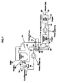
- FIG. 1 is a flow diagram of an oxy-fired pulverized coal combustion system including a secondary oxygen mixer located upstream oxidant flow-wise of a tri-sentor regenerative oxidant preheater;
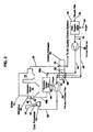
- FIG. 2 is a flow diagram of an oxy-fired coal combustion system including a secondary oxygen mixer located downstream oxidant flow-wise of a trisector regenerative oxidant preheater;
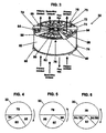
- FIG. 3 is a diagrammatic perspective view of the rotor and the sectors of the regenerative oxidant preheater
- FIG. 4 is a simplified representation of one embodiment of the sectors of the regenerative oxidant preheater
- FIG. 5 is a simplified representation of another embodiment of the sectors of the regenerative oxidant preheater
- FIG. 6 is a simplified representation of still another embodiment of the sectors of the regenerative oxidant preheater
- FIG. 7 is a graphical presentation of the pressure profiles through a prior art or conventional regenerative oxidant preheater
- FIG. 8 is a graphical presentation of the pressure profiles through an embodiment of a trisector regenerative oxidant preheater.
- the present invention resides in reducing oxidant leakage from the oxidant side to the gas side of a rotary regenerative oxidant preheater.
- FIGS. 1 and 2 there is shown, diagrammatically, a tri-sector regenerative oxidant preheater for heating the primary and secondary oxygen enriched flue gas, hereinafter referred to as an oxidant.
- the boiler is generally shown at 10 and includes a combustion space 12.
- Coal is supplied to a pulverizer 14 from a coal delivery system which includes a coal bunker 16 discharging coal into the pulverizer 14 through a conduit 18.
- the oxidant delivery system includes a main oxygen mixer 20 which receives a recycled flue gas 22 resulting from the coal combustion process and an oxygen stream 24 which has a purity of about 95%.
- the oxygen enriched flue gas or oxidant stream is conveyed through ductwork 26.
- a greater portion of the oxidant stream represents the secondary oxidant and is delivered to the suction side of a forced draft fan 28, while the remainder of the oxidant stream represents the primary oxidant and is delivered to the ductwork 30.
- the primary oxidant is conveyed through ductwork 30 to the tri-sector regenerative oxidant preheater 32, as also shown in FIGS. 3-6 , it is heated as it passes through primary oxidant sectors 84 and 86 of preheater 32.
- the heated primary oxidant streams exiting sections sectors 84 and 86 of preheater 32 are conveyed to a common ductwork 34 and delivered to the suction side of a primary oxidant fan 36.
- the primary oxidant exiting the fan 36 is conveyed through ductwork 38 to the pulverizer 14 where it dries and sweeps the pulverized coal and carries it through a conduit 40 to burner 42 which mixes the pulverized coal and primary oxidant with the secondary oxidant to establish a stable flame in the combustion space 12.
- the secondary oxidant exiting the forced draft fan 28 is conveyed to a secondary oxygen mixer 44, wherein the secondary oxidant is further enriched with an oxygen stream 46.
- the further enriched secondary oxidant is conveyed to the trisector regenerative oxidant preheater 32 where, as also shown in FIGS. 3-6 , it is heated as it passes through sector 82 of preheater 32.
- the heated secondary oxidant exiting sector 82 of preheater 32 is conveyed through ductwork 48 to a windbox 50 which houses the coal burners, such as the one depicted at 42, and mixes the secondary oxidant with the pulverized coal and primary oxidant, introduced by the burner 42, in a manner that establishes a stable flame in the combustion space 12.
- the pulverized coal is burned in the combustion space 12, and the resulting hot flue gas flows through a convection pass 13 containing heat exchange surfaces, not shown.
- the hot flue gas leaving the convection pass 13 is conveyed through ductwork 15 to the flue gas sector 78 of preheater 32 where it gives up heat to the primary and secondary oxidants flowing through the oxidant sectors. 82, 84, and. 86 of preheater 32.
- the cooled flue gas leaving preheater 32 is conveyed to an air quality control system with about 70% to 80% of the flue gas being recycled back to the boiler 10 as oxidant.
- FIG. 2 there is shown an alternative arrangement wherein the ductwork 48 split into sections. 48a and 48b with the secondary oxygen mixer 44 being operatively located between the ductwork sections 48a and 48b, and downstream oxidant flow-wise of the tri-sector preheater 32.
- the oxidant exiting the sector 82 is conveyed through ductwork section 48a to the secondary oxygen mixer 44, wherein the secondary oxidant is further enriched with an oxygen stream 46.
- the further enriched oxidant exiting the mixer 44 is conveyed through ductwork section 48b to the windbox 50.
- the oxidant preheater 32 has a rotor 60 coaxially and rotatably mounted in a shell or housing 62.
- the rotor 60 is divided by partitions 64 extending radially outward from a center post 66 to the rotor shell 62, and thus dividing the rotor 60 into pie shaped compartments 70 containing heat exchanger elements 72.
- the oxidant preheater 32 is divided by sector plates 74 into an oxidant sector 76 and a flue gas sector 78.
- the oxidant sector 76 is subdivided by sector plates 80 into a secondary oxidant sector 82 and two primary oxidant sectors 84 and 86.
- the secondary oxidant sector 82 is located between the primary oxidant sectors 84 and 86, and the primary oxidant sectors 84 and 86 are located adjacent to the flue gas sector 78 and the secondary oxidant sector 82. Thus, the secondary oxidant sector 82 is not adjacent the flue gas sector 78.
- FIGS. 4 - 6 there are shown simplified representations of a tri-sector regenerative oxidant preheater 32.
- the primary oxidant flows through sectors 84 and 86, which border the flue gas sector 78.
- the secondary oxidant flows through sector 82 which is interposed between the sectors 84 and 86.
- the primary oxidant fan 36 is located downstream oxidant flow-wise of the preheater 32, as shown in FIGS. 1 and 2 .
- the primary oxidant is drawn through sectors 84 and 86 of the preheater 32 by the primary oxidant fan 36, thus creating an environment in the primary oxidant sectors 84 and 86, wherein the primary oxidant flowing therethrough is at a negative pressure of about a 5 inches wg.
- the secondary oxidant is forced through sector 82 of the preheater 32 by the forced draft fan 28 which is located upstream gas flowwise of the preheater 32, as shown in FIGS. 1 and 2 , thus creating an environment in the secondary oxidant sector 82, wherein the secondary oxidant flowing therethrough is at a positive pressure of about 20 inches wg.
- the flue gas is drawn through sector 78 of the preheater 32 by an induced draft fan, not shown, thus creating an environment in the flue gas sector 78, wherein the flue gas is at a negative pressure of about 5 inches wg.
- the pressure difference between the flue gas sector 78 and the primary oxidant sectors 84 and 86 is insignificant and thus nearly eliminates leakage from the oxidant side to the gas side of preheater 32.
- the pressure difference between the secondary oxidant sector 82 and the primary oxidant sectors 84 and 86 is about 25 inches wg., but any leakage sector 82 and sectors 84 and 86 would be oxidant from sector 82 to oxidant in sectors 84 and 86 and there would not be a loss of oxygen to the gas side of preheater 32 from the secondary oxidant sector 82.
- FIG. 4 there is shown a simplified representation of a. trisector regenerative oxidant preheater 32 whose rotation is clockwise.
- the primary oxidant sector 86 borders the 3 o'clock side of the flue gas sector 78, and is sized to deliver the required primary oxidant temperature.
- the primary oxidant sector 84 borders 9 o'clock side of the flue gas sector 78, and is sized for the minimum required to substantially preclude the leakage of oxidant into the flue gas sector 78, since there is little heat left as the heat exchanger elements 72 and the rotor 60, both shown in FIG. 3 , pass through sector 84 of the preheater 32.
- the secondary oxidant sector 82 is interposed between the primary oxidant sectors 84 and 86, and is sized to deliver the required secondary oxidant temperature.
- FIG. 5 there is shown a simplified representation of a trisector regenerative oxidant preheater 32 whose rotation is counterclockwise.
- the primary oxidant sector 86 borders the 9 o'clock side of the flue gas sector 78, and is sized to deliver the required primary oxidant temperature.
- the primary oxidant sector 84 borders the 3 o'clock side of the flue gas sector 78, and is sized for the minimum required to substantially preclude the leakage of oxidant into the flue gas sector 78, since there is little heat left as the heat exchanger elements 72 and the rotor 60, both shown in FIG. 3 , pass through sector 84 of the preheater 32.
- the secondary oxidant sector 82 is interposed between the primary oxidant sectors 84 and 86, and is sized to deliver the required secondary oxidant temperature.
- FIG. 6 there is shown a simplified representation of a trisector regenerative oxidant preheater 32 whose rotation can be either clockwise or counterclockwise.
- the primary oxidant sectors 84/86 bordering the 3 o'clock and 9 o'clock sides of the flue gas sector 78, are of substantially equal size and, when taken together, are sized to deliver the required primary air temperature.
- the secondary oxidant sector 82 is interposed between the primary oxidant sectors 84/86, and is sized to deliver the required secondary oxidant temperature.
- FIG. 7 there is shown a graphical presentation of the oxidant and flue gas pressure profiles of a prior art or conventional oxidant preheater.
- the pressure of the oxidant entering the preheater POi is positive and is much higher than the negative pressure flue gas leaving the preheater Pgo.
- the pressure of the oxidant leaving the preheater POo is positive, and remains much higher than the negative pressure flue gas entering leaving the preheater Pgi.
- the large pressure difference between the positive pressure oxidant and the negative pressure flue gas, passing through the preheater, causes leakage of oxidant into the gas side of the preheater.
- FIG. 8 there is shown a graphical presentation of the oxidant and flue pressure profiles of the present invention.
- the pressure of the oxidant entering the preheater POi is somewhat less negative than the negative pressure flue gas leaving the preheater Pgo.
- the pressure of the oxidant leaving the preheater POo is somewhat more negative than the negative pressure flue gas entering the preheater Pgi.
- the somewhat lesser negative pressure of the oxidant entering the preheater POi results in a slight leakage of oxidant into the gas side of the preheater.
- the somewhat lesser negative pressure of the flue gas entering the preheater Pgi results in a slight leakage of flue gas into the oxidant side of the preheater.
Landscapes
- Engineering & Computer Science (AREA)
- Mechanical Engineering (AREA)
- General Engineering & Computer Science (AREA)
- Chemical & Material Sciences (AREA)
- Combustion & Propulsion (AREA)
- Physics & Mathematics (AREA)
- Thermal Sciences (AREA)
- Air Supply (AREA)
Applications Claiming Priority (2)
| Application Number | Priority Date | Filing Date | Title |
|---|---|---|---|
| US94878407P | 2007-07-10 | 2007-07-10 | |
| US12/169,168 US8327809B2 (en) | 2007-07-10 | 2008-07-08 | Tri-sector regenerative oxidant preheater for oxy-fired pulverized coal combustion |
Publications (2)
| Publication Number | Publication Date |
|---|---|
| EP2014976A2 true EP2014976A2 (de) | 2009-01-14 |
| EP2014976A3 EP2014976A3 (de) | 2017-10-18 |
Family
ID=39864745
Family Applications (1)
| Application Number | Title | Priority Date | Filing Date |
|---|---|---|---|
| EP08160135.3A Withdrawn EP2014976A3 (de) | 2007-07-10 | 2008-07-10 | Regenerativer dreiteiliger Oxidationsmittelvorwärmer für sauerstoffbefeuerte Kohlenstaubfeuerung |
Country Status (2)
| Country | Link |
|---|---|
| EP (1) | EP2014976A3 (de) |
| CA (1) | CA2637489C (de) |
Cited By (4)
| Publication number | Priority date | Publication date | Assignee | Title |
|---|---|---|---|---|
| WO2010132143A3 (en) * | 2009-05-14 | 2011-06-30 | Alstom Technology Ltd | Regenerative heat exchanger and method of reducing gas leakage therein |
| CN107782480A (zh) * | 2017-11-17 | 2018-03-09 | 北京石油化工学院 | 一种可燃粉尘/可燃气体杂混物最小着火能量的测试方法及装置 |
| CN110440282A (zh) * | 2019-07-17 | 2019-11-12 | 华电电力科学研究院有限公司 | 管式和两分仓式回转式空气预热器组合的节能防堵型空气预热器系统及其工作方法 |
| CN110563235A (zh) * | 2019-09-06 | 2019-12-13 | 山东理工大学 | 液体罐车蒸洗罐体废水-废气联合治理设备与工艺 |
Citations (2)
| Publication number | Priority date | Publication date | Assignee | Title |
|---|---|---|---|---|
| US6202574B1 (en) * | 1999-07-09 | 2001-03-20 | Abb Alstom Power Inc. | Combustion method and apparatus for producing a carbon dioxide end product |
| WO2006120371A1 (en) * | 2005-03-22 | 2006-11-16 | Howden Uk Limited | A rotary heat exchanger and a method of reducing leakage in a rotary heat exchanger |
Family Cites Families (4)
| Publication number | Priority date | Publication date | Assignee | Title |
|---|---|---|---|---|
| US5915339A (en) * | 1995-06-29 | 1999-06-29 | Abb Air Preheater Inc. | Sector plate and seal arrangement for trisector air preheater |
| DE19602114A1 (de) * | 1996-01-22 | 1997-07-24 | Steinmueller Gmbh L & C | Regenerativ-Drehluftvorwärmer |
| US5915340A (en) * | 1996-10-02 | 1999-06-29 | Abb Air Preheater Inc. | Variable sector plate quad sector air preheater |
| US7082987B2 (en) * | 2000-01-19 | 2006-08-01 | Howden Power Limited | Rotary regenerative heat exchanger and rotor therefor |
-
2008
- 2008-07-09 CA CA2637489A patent/CA2637489C/en not_active Expired - Fee Related
- 2008-07-10 EP EP08160135.3A patent/EP2014976A3/de not_active Withdrawn
Patent Citations (2)
| Publication number | Priority date | Publication date | Assignee | Title |
|---|---|---|---|---|
| US6202574B1 (en) * | 1999-07-09 | 2001-03-20 | Abb Alstom Power Inc. | Combustion method and apparatus for producing a carbon dioxide end product |
| WO2006120371A1 (en) * | 2005-03-22 | 2006-11-16 | Howden Uk Limited | A rotary heat exchanger and a method of reducing leakage in a rotary heat exchanger |
Cited By (6)
| Publication number | Priority date | Publication date | Assignee | Title |
|---|---|---|---|---|
| WO2010132143A3 (en) * | 2009-05-14 | 2011-06-30 | Alstom Technology Ltd | Regenerative heat exchanger and method of reducing gas leakage therein |
| CN102575907A (zh) * | 2009-05-14 | 2012-07-11 | 阿尔斯通技术有限公司 | 再生热交换器及减少其内部气体泄漏的方法 |
| CN107782480A (zh) * | 2017-11-17 | 2018-03-09 | 北京石油化工学院 | 一种可燃粉尘/可燃气体杂混物最小着火能量的测试方法及装置 |
| CN107782480B (zh) * | 2017-11-17 | 2023-08-29 | 北京石油化工学院 | 一种可燃粉尘/可燃气体杂混物最小着火能量的测试方法及装置 |
| CN110440282A (zh) * | 2019-07-17 | 2019-11-12 | 华电电力科学研究院有限公司 | 管式和两分仓式回转式空气预热器组合的节能防堵型空气预热器系统及其工作方法 |
| CN110563235A (zh) * | 2019-09-06 | 2019-12-13 | 山东理工大学 | 液体罐车蒸洗罐体废水-废气联合治理设备与工艺 |
Also Published As
| Publication number | Publication date |
|---|---|
| EP2014976A3 (de) | 2017-10-18 |
| CA2637489A1 (en) | 2009-01-10 |
| CA2637489C (en) | 2015-06-16 |
Similar Documents
| Publication | Publication Date | Title |
|---|---|---|
| US8327809B2 (en) | Tri-sector regenerative oxidant preheater for oxy-fired pulverized coal combustion | |
| JP6099706B2 (ja) | 酸素燃料燃焼式再生オキシダントヒーターの内部構成 | |
| US6247315B1 (en) | Oxidant control in co-generation installations | |
| CA2637489C (en) | Tri-sector regenerative oxidant preheater for oxy-fired pulverized coal combustion | |
| US9581330B2 (en) | Oxy-fuel combustion oxidant heater internal arrangement | |
| CN121511378A (zh) | 燃烧器及具备该燃烧器的锅炉以及燃烧器的运转方法 | |
| US20220325888A1 (en) | Combustion system comprising an annular shroud burner | |
| JP5854620B2 (ja) | ボイラ及びボイラの運転方法 | |
| EP2457020B1 (de) | Verbrennungsvorrichtung | |
| JP6109718B2 (ja) | ボイラ | |
| JP2014085050A (ja) | ボイラ | |
| CN103591602A (zh) | 并联混合式多级空气预热器 | |
| TWI858471B (zh) | 燃燒器及鍋爐 | |
| JP2008164188A (ja) | 微粉炭焚き貫流ボイラ及び微粉炭焚き貫流ボイラを備えた発電プラント | |
| McDonald et al. | 30 MWt Clean Environment Development Oxy-Coal Combustion Test Program | |
| EP2589914A1 (de) | Drehbarer regenerativer Wärmetauscher | |
| JP7860788B2 (ja) | バーナ、及びボイラ | |
| TW201337179A (zh) | 旋轉再生熱交換器 | |
| CN106179685A (zh) | 塔式350mw超临界锅炉的风扇磨布置系统及布置方法 | |
| CN204786353U (zh) | 一种燃用褐煤制粉系统 | |
| SU802693A1 (ru) | Котельна установка | |
| JP2015102298A (ja) | ボイラ | |
| JP2015096789A (ja) | ボイラ | |
| Garg et al. | Make every BTU count | |
| CN106196135A (zh) | π型350MW超临界锅炉的风扇磨布置系统及布置方法 |
Legal Events
| Date | Code | Title | Description |
|---|---|---|---|
| PUAI | Public reference made under article 153(3) epc to a published international application that has entered the european phase |
Free format text: ORIGINAL CODE: 0009012 |
|
| AK | Designated contracting states |
Kind code of ref document: A2 Designated state(s): AT BE BG CH CY CZ DE DK EE ES FI FR GB GR HR HU IE IS IT LI LT LU LV MC MT NL NO PL PT RO SE SI SK TR |
|
| AX | Request for extension of the european patent |
Extension state: AL BA MK RS |
|
| RAP1 | Party data changed (applicant data changed or rights of an application transferred) |
Owner name: THE BABCOCK & WILCOX COMPANY |
|
| PUAL | Search report despatched |
Free format text: ORIGINAL CODE: 0009013 |
|
| AK | Designated contracting states |
Kind code of ref document: A3 Designated state(s): AT BE BG CH CY CZ DE DK EE ES FI FR GB GR HR HU IE IS IT LI LT LU LV MC MT NL NO PL PT RO SE SI SK TR |
|
| AX | Request for extension of the european patent |
Extension state: AL BA MK RS |
|
| RIC1 | Information provided on ipc code assigned before grant |
Ipc: F28D 19/04 20060101ALI20170908BHEP Ipc: F23L 15/02 20060101ALI20170908BHEP Ipc: F23L 7/00 20060101ALI20170908BHEP Ipc: F23D 1/00 20060101AFI20170908BHEP |
|
| STAA | Information on the status of an ep patent application or granted ep patent |
Free format text: STATUS: REQUEST FOR EXAMINATION WAS MADE |
|
| 17P | Request for examination filed |
Effective date: 20180418 |
|
| RBV | Designated contracting states (corrected) |
Designated state(s): AT BE BG CH CY CZ DE DK EE ES FI FR GB GR HR HU IE IS IT LI LT LU LV MC MT NL NO PL PT RO SE SI SK TR |
|
| AKX | Designation fees paid |
Designated state(s): AT BE BG CH CY CZ DE DK EE ES FI FR GB GR HR HU IE IS IT LI LT LU LV MC MT NL NO PL PT RO SE SI SK TR |
|
| AXX | Extension fees paid |
Extension state: BA Extension state: AL Extension state: RS Extension state: MK |
|
| STAA | Information on the status of an ep patent application or granted ep patent |
Free format text: STATUS: EXAMINATION IS IN PROGRESS |
|
| 17Q | First examination report despatched |
Effective date: 20181219 |
|
| GRAP | Despatch of communication of intention to grant a patent |
Free format text: ORIGINAL CODE: EPIDOSNIGR1 |
|
| STAA | Information on the status of an ep patent application or granted ep patent |
Free format text: STATUS: GRANT OF PATENT IS INTENDED |
|
| INTG | Intention to grant announced |
Effective date: 20200313 |
|
| RAP1 | Party data changed (applicant data changed or rights of an application transferred) |
Owner name: THE BABCOCK & WILCOX COMPANY |
|
| STAA | Information on the status of an ep patent application or granted ep patent |
Free format text: STATUS: THE APPLICATION IS DEEMED TO BE WITHDRAWN |
|
| 18D | Application deemed to be withdrawn |
Effective date: 20200724 |