EP2014875A2 - Gasturbinensysteme mit Dichtstreifen - Google Patents
Gasturbinensysteme mit Dichtstreifen Download PDFInfo
- Publication number
- EP2014875A2 EP2014875A2 EP08252298A EP08252298A EP2014875A2 EP 2014875 A2 EP2014875 A2 EP 2014875A2 EP 08252298 A EP08252298 A EP 08252298A EP 08252298 A EP08252298 A EP 08252298A EP 2014875 A2 EP2014875 A2 EP 2014875A2
- Authority
- EP
- European Patent Office
- Prior art keywords
- tab
- feather seal
- slot
- vane
- gas turbine
- Prior art date
- Legal status (The legal status is an assumption and is not a legal conclusion. Google has not performed a legal analysis and makes no representation as to the accuracy of the status listed.)
- Granted
Links
Images

Classifications
-
- F—MECHANICAL ENGINEERING; LIGHTING; HEATING; WEAPONS; BLASTING
- F01—MACHINES OR ENGINES IN GENERAL; ENGINE PLANTS IN GENERAL; STEAM ENGINES
- F01D—NON-POSITIVE DISPLACEMENT MACHINES OR ENGINES, e.g. STEAM TURBINES
- F01D11/00—Preventing or minimising internal leakage of working-fluid, e.g. between stages
- F01D11/005—Sealing means between non relatively rotating elements
- F01D11/006—Sealing the gap between rotor blades or blades and rotor
- F01D11/008—Sealing the gap between rotor blades or blades and rotor by spacer elements between the blades, e.g. independent interblade platforms
-
- F—MECHANICAL ENGINEERING; LIGHTING; HEATING; WEAPONS; BLASTING
- F01—MACHINES OR ENGINES IN GENERAL; ENGINE PLANTS IN GENERAL; STEAM ENGINES
- F01D—NON-POSITIVE DISPLACEMENT MACHINES OR ENGINES, e.g. STEAM TURBINES
- F01D11/00—Preventing or minimising internal leakage of working-fluid, e.g. between stages
- F01D11/005—Sealing means between non relatively rotating elements
-
- F—MECHANICAL ENGINEERING; LIGHTING; HEATING; WEAPONS; BLASTING
- F01—MACHINES OR ENGINES IN GENERAL; ENGINE PLANTS IN GENERAL; STEAM ENGINES
- F01D—NON-POSITIVE DISPLACEMENT MACHINES OR ENGINES, e.g. STEAM TURBINES
- F01D9/00—Stators
- F01D9/02—Nozzles; Nozzle boxes; Stator blades; Guide conduits, e.g. individual nozzles
- F01D9/04—Nozzles; Nozzle boxes; Stator blades; Guide conduits, e.g. individual nozzles forming ring or sector
- F01D9/041—Nozzles; Nozzle boxes; Stator blades; Guide conduits, e.g. individual nozzles forming ring or sector using blades
-
- F—MECHANICAL ENGINEERING; LIGHTING; HEATING; WEAPONS; BLASTING
- F05—INDEXING SCHEMES RELATING TO ENGINES OR PUMPS IN VARIOUS SUBCLASSES OF CLASSES F01-F04
- F05D—INDEXING SCHEME FOR ASPECTS RELATING TO NON-POSITIVE-DISPLACEMENT MACHINES OR ENGINES, GAS-TURBINES OR JET-PROPULSION PLANTS
- F05D2240/00—Components
- F05D2240/80—Platforms for stationary or moving blades
-
- F—MECHANICAL ENGINEERING; LIGHTING; HEATING; WEAPONS; BLASTING
- F05—INDEXING SCHEMES RELATING TO ENGINES OR PUMPS IN VARIOUS SUBCLASSES OF CLASSES F01-F04
- F05D—INDEXING SCHEME FOR ASPECTS RELATING TO NON-POSITIVE-DISPLACEMENT MACHINES OR ENGINES, GAS-TURBINES OR JET-PROPULSION PLANTS
- F05D2260/00—Function
- F05D2260/94—Functionality given by mechanical stress related aspects such as low cycle fatigue [LCF] of high cycle fatigue [HCF]
- F05D2260/941—Functionality given by mechanical stress related aspects such as low cycle fatigue [LCF] of high cycle fatigue [HCF] particularly aimed at mechanical or thermal stress reduction
Definitions
- the disclosure generally relates to seals used in gas turbine engines.
- Turbine vane assemblies are examples of components that typically experience expansion and contraction during use.
- feather seals have been used.
- a feather seal which is typically configured as a strip of metal, is positioned between opposing slots of adjacent vanes.
- the feather seal typically floats loosely within the opposing slots.
- the feather seal tends to fit more tightly within the opposing slots.
- the width of a feather seal may be established so that the seal will not fall out of the slots when the vanes cool and contract.
- the width should be narrow enough so that the vanes do not crush the feather seal when the vanes heat and expand.
- an exemplary embodiment of a vane assembly for a gas turbine engine comprises: a first mounting platform having a first slot; a first airfoil extending from the first mounting platform; and a feather seal having opposing faces, a first side extending between the faces, and a first tab, the first tab extending outwardly beyond the first side; the first slot being sized and shaped to receive the feather seal including the first tab.
- An exemplary embodiment of a feather seal for a gas turbine engine comprises: opposing faces; a first side extending between the faces; and a first tab extending outwardly beyond the first side, the first tab being located in a plane defined by the opposing faces.
- An exemplary embodiment of a gas turbine engine comprises: a compressor; a combustion section; and a turbine operative to drive the compressor responsive to energy imparted thereto by the combustion section, the turbine having a vane assembly, the vane assembly having a first vane comprising: a first mounting platform having a first slot; a first airfoil extending from the first mounting platform; and a feather seal having opposing faces, a first side and a first tab, the first side extending between the faces, the first tab extending outwardly beyond the first side; the first slot being sized and shaped to receive the feather seal including the first tab.
- a feather seal that incorporates at least a first tab that effectively widens the feather seal at the location of the tab.
- the tab is configured to be received by a corresponding feature of a vane.
- the feature can be a cavity or through-hole into which the tab is inserted.
- the feather seal can be designed narrow enough to limit component weight, while the tab effectively widens the feather seal. That is, the tab locally widens the feather seal so that the feather seal does not tend to fall out of place when the vane contracts during cooling.
- one or more tabs of a feather seal can be sized for preventing fall-out and remaining portions of the feather seal can be sized to accommodate crushing considerations.
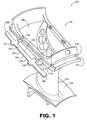
- system 100 incorporates a vane 102 and a feather seal 104.
- vane 102 incorporates an outer mounting platform 106, an inner mounting platform 108, and an airfoil 110 extending between the outer mounting platform and the inner mounting platform.
- the outer mounting platform includes rails 112 and 114, which define slots 116 and 118, respectively. The slots are sized and shaped to receive a portion of the feather seal.
- Feather seal 104 is generally elongate, exhibiting a longitudinal axis, and is planar.
- the feather seal is formed of a strip of material, e.g. a Cobalt alloy, such as Haynes-188.
- the feather seal has opposing faces 120, 122, sidewalls 124, 126 extending between the faces, and endwalls 128, 130 extending between the faces and between the sidewalls.
- the feather seal of this embodiment is generally rectangular.
- Tabs 131, 132, 133 and 134 extend outwardly beyond the sidewalls of the feather seal.
- tabs 131 and 133 extend beyond sidewall 124
- tabs 132 and 134 extend beyond sidewall 126.
- the tabs are generally rectangular and are positioned in opposing pairs along a length of the feather seal.
- various other numbers, shapes and/or arrangements of tabs can be used.
- one or more portions of the tabs could be tapered, such as by incorporating a chamfer.
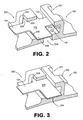
- FIG. 2 schematically depicts the embodiment of FIG. 1 positioned next to an adjacent vane 202, with the feather seal 104 installed to seal a gap formed between vane 102 and vane 202. Specifically, when in the installed position shown in FIG. 2 , a gap 204 is formed between the vanes when the vanes are cold.
- slot 116 is defined by a backwall 210, and walls 212 and 214 that are spaced from each other and that extend from backwall 210.
- slot 206 is defined by a backwall 220, and walls 222 and 224 that are spaced from each other and that extend from 220 backwall.
- Each of the slots communicates with a corresponding through-hole that is configured to receive a tab.
- slot 116 communicates with through-hole 231 and slot 206 communicates with through-hole 232.
- the through-holes are formed by the material of the walls that define the rails. Additionally, each incorporates a recess.
- the feather seal is not wide enough at non-tabbed locations to extend from the backwall of one rail to the backwall of the other.
- the tabs tend to prevent the feather seal from falling out of the slots by spanning the gap 204 between the adjacent vanes.
- FIG. 3 depicts the embodiment of FIG. 2 after heating; thus, the vanes have expanded.
- the gap 204 between the adjacent vanes has significantly reduced in size such that the non-tabbed locations of the feather seal are in close proximity to the backwalls of the rails.
- the through-holes have accommodated repositioning of the tabs by enabling more material of the tabs to be inserted through the through-holes.
- the feather seal is not crushed.
- vane 400 includes an outer mounting platform 402, a portion of which is depicted.
- outer mounting platform 402 includes a rail 404 and a feature for receiving a tab of a feather seal.
- the feature is a cavity 406 that incorporates an entrance 408.
- a tab of a feather seal (not shown) can be inserted into the cavity via the entrance.
- any gas leakage that may occur in a vicinity of the tab can be contained by the sealed cavity.
- construction of the sealed cavity is facilitated by casting a lower portion 410 of material that defines the cavity integrally with the outer mounting platform; however, other techniques can be used in other embodiments. This casting results in an opening 412 for facilitating release and holding of the component during manufacture. Sealing of the cavity is accomplished by attaching a wall 414, in this case a plate, to the cast portion. In some embodiments, such as here, this can accomplished by welding the plate to the outer mounting platform.
- FIG. 5 Another embodiment of a vane is depicted schematically in FIG. 5 .
- This embodiment differs from that depicted in FIG. 4 by incorporating a casting feature that can be sealed without the use of a wall.
- vane 500 includes an outer mounting platform 502, a portion of which is depicted.
- outer mounting platform 502 includes a rail 504 and a cavity 506 that incorporates an entrance 508.
- the sealed cavity is constructed by casting a lower portion 510 of the cavity integrally with the outer mounting platform. This casting results in an opening 512 for facilitating release of the component during manufacture.
- opening 512 can be sealed by welding the opening closed without using a wall. In other embodiments, such an opening may not be incorporated into the final component as other manufacturing methods could be used.
- FIG. 5 also depicts recess 520 that extends from the cavity and into a wall 522 that partially defines slot 524.
- recess 520 is generally rectangular and extends along the floor of the cavity 506.
- a recess may be avoided. However, such a recess can be used to ensure that a ridge or other raised surface is not present along the intersection of the cavity and the slot as may be caused by different manufacturing techniques for forming the cavity and slot.
Landscapes
- Engineering & Computer Science (AREA)
- Mechanical Engineering (AREA)
- General Engineering & Computer Science (AREA)
- Turbine Rotor Nozzle Sealing (AREA)
Applications Claiming Priority (1)
| Application Number | Priority Date | Filing Date | Title |
|---|---|---|---|
| US11/775,330 US8182208B2 (en) | 2007-07-10 | 2007-07-10 | Gas turbine systems involving feather seals |
Publications (3)
| Publication Number | Publication Date |
|---|---|
| EP2014875A2 true EP2014875A2 (de) | 2009-01-14 |
| EP2014875A3 EP2014875A3 (de) | 2011-12-21 |
| EP2014875B1 EP2014875B1 (de) | 2016-03-23 |
Family
ID=39730668
Family Applications (1)
| Application Number | Title | Priority Date | Filing Date |
|---|---|---|---|
| EP08252298.8A Active EP2014875B1 (de) | 2007-07-10 | 2008-07-04 | Gasturbinensysteme mit Dichtstreifen |
Country Status (2)
| Country | Link |
|---|---|
| US (1) | US8182208B2 (de) |
| EP (1) | EP2014875B1 (de) |
Cited By (3)
| Publication number | Priority date | Publication date | Assignee | Title |
|---|---|---|---|---|
| EP3000981A1 (de) * | 2014-09-29 | 2016-03-30 | Siemens Aktiengesellschaft | Anordnung zum Abdichten des Spaltes zwischen zwei Segmenten eines Leitschaufelrings |
| EP2551462A3 (de) * | 2011-07-29 | 2017-11-15 | Rolls-Royce plc | Schnappdichtung und Abdichtungsvorrichtung |
| EP2048328B1 (de) * | 2007-10-09 | 2019-05-08 | United Technologies Corporation | Rückhaltefunktion für eine Dichteinrichtung |
Families Citing this family (52)
| Publication number | Priority date | Publication date | Assignee | Title |
|---|---|---|---|---|
| US20090096174A1 (en) * | 2007-02-28 | 2009-04-16 | United Technologies Corporation | Blade outer air seal for a gas turbine engine |
| EP2436884A1 (de) * | 2010-09-29 | 2012-04-04 | Siemens Aktiengesellschaft | Turbinenanordnung und Gasturbinenmotor |
| US9403208B2 (en) | 2010-12-30 | 2016-08-02 | United Technologies Corporation | Method and casting core for forming a landing for welding a baffle inserted in an airfoil |
| US8845285B2 (en) | 2012-01-10 | 2014-09-30 | General Electric Company | Gas turbine stator assembly |
| US8905708B2 (en) * | 2012-01-10 | 2014-12-09 | General Electric Company | Turbine assembly and method for controlling a temperature of an assembly |
| US9103222B2 (en) | 2012-06-22 | 2015-08-11 | United Technologies Corporation | Turbine engine variable area vane with feather seal |
| US9273566B2 (en) | 2012-06-22 | 2016-03-01 | United Technologies Corporation | Turbine engine variable area vane |
| US10215048B2 (en) | 2013-01-21 | 2019-02-26 | United Technologies Corporation | Variable area vane arrangement for a turbine engine |
| US10072517B2 (en) | 2013-03-08 | 2018-09-11 | United Technologies Corporation | Gas turbine engine component having variable width feather seal slot |
| US10822980B2 (en) | 2013-04-11 | 2020-11-03 | Raytheon Technologies Corporation | Gas turbine engine stress isolation scallop |
| US10415407B2 (en) | 2016-11-17 | 2019-09-17 | United Technologies Corporation | Airfoil pieces secured with endwall section |
| US10309226B2 (en) | 2016-11-17 | 2019-06-04 | United Technologies Corporation | Airfoil having panels |
| US10436049B2 (en) | 2016-11-17 | 2019-10-08 | United Technologies Corporation | Airfoil with dual profile leading end |
| US10711794B2 (en) | 2016-11-17 | 2020-07-14 | Raytheon Technologies Corporation | Airfoil with geometrically segmented coating section having mechanical secondary bonding feature |
| US10767487B2 (en) | 2016-11-17 | 2020-09-08 | Raytheon Technologies Corporation | Airfoil with panel having flow guide |
| US10711616B2 (en) | 2016-11-17 | 2020-07-14 | Raytheon Technologies Corporation | Airfoil having endwall panels |
| US10480331B2 (en) | 2016-11-17 | 2019-11-19 | United Technologies Corporation | Airfoil having panel with geometrically segmented coating |
| US10408090B2 (en) | 2016-11-17 | 2019-09-10 | United Technologies Corporation | Gas turbine engine article with panel retained by preloaded compliant member |
| US10808554B2 (en) | 2016-11-17 | 2020-10-20 | Raytheon Technologies Corporation | Method for making ceramic turbine engine article |
| US10746038B2 (en) | 2016-11-17 | 2020-08-18 | Raytheon Technologies Corporation | Airfoil with airfoil piece having radial seal |
| US10677079B2 (en) | 2016-11-17 | 2020-06-09 | Raytheon Technologies Corporation | Airfoil with ceramic airfoil piece having internal cooling circuit |
| US10309238B2 (en) | 2016-11-17 | 2019-06-04 | United Technologies Corporation | Turbine engine component with geometrically segmented coating section and cooling passage |
| US10662779B2 (en) | 2016-11-17 | 2020-05-26 | Raytheon Technologies Corporation | Gas turbine engine component with degradation cooling scheme |
| US10711624B2 (en) | 2016-11-17 | 2020-07-14 | Raytheon Technologies Corporation | Airfoil with geometrically segmented coating section |
| US10428663B2 (en) | 2016-11-17 | 2019-10-01 | United Technologies Corporation | Airfoil with tie member and spring |
| US10570765B2 (en) | 2016-11-17 | 2020-02-25 | United Technologies Corporation | Endwall arc segments with cover across joint |
| US10677091B2 (en) | 2016-11-17 | 2020-06-09 | Raytheon Technologies Corporation | Airfoil with sealed baffle |
| US10502070B2 (en) | 2016-11-17 | 2019-12-10 | United Technologies Corporation | Airfoil with laterally insertable baffle |
| US10731495B2 (en) | 2016-11-17 | 2020-08-04 | Raytheon Technologies Corporation | Airfoil with panel having perimeter seal |
| US10605088B2 (en) | 2016-11-17 | 2020-03-31 | United Technologies Corporation | Airfoil endwall with partial integral airfoil wall |
| US10662782B2 (en) | 2016-11-17 | 2020-05-26 | Raytheon Technologies Corporation | Airfoil with airfoil piece having axial seal |
| US10436062B2 (en) | 2016-11-17 | 2019-10-08 | United Technologies Corporation | Article having ceramic wall with flow turbulators |
| US10598029B2 (en) | 2016-11-17 | 2020-03-24 | United Technologies Corporation | Airfoil with panel and side edge cooling |
| US10408082B2 (en) | 2016-11-17 | 2019-09-10 | United Technologies Corporation | Airfoil with retention pocket holding airfoil piece |
| US10458262B2 (en) | 2016-11-17 | 2019-10-29 | United Technologies Corporation | Airfoil with seal between endwall and airfoil section |
| US10598025B2 (en) | 2016-11-17 | 2020-03-24 | United Technologies Corporation | Airfoil with rods adjacent a core structure |
| US10480334B2 (en) | 2016-11-17 | 2019-11-19 | United Technologies Corporation | Airfoil with geometrically segmented coating section |
| US10428658B2 (en) | 2016-11-17 | 2019-10-01 | United Technologies Corporation | Airfoil with panel fastened to core structure |
| US10907491B2 (en) * | 2017-11-30 | 2021-02-02 | General Electric Company | Sealing system for a rotary machine and method of assembling same |
| CN111936725B (zh) * | 2018-03-30 | 2022-08-16 | 西门子能源全球两合公司 | 涡轮机护罩段之间的密封布置 |
| US10927692B2 (en) * | 2018-08-06 | 2021-02-23 | General Electric Company | Turbomachinery sealing apparatus and method |
| US11319827B2 (en) * | 2019-04-01 | 2022-05-03 | Raytheon Technologies Corporation | Intersegment seal for blade outer air seal |
| US11156116B2 (en) | 2019-04-08 | 2021-10-26 | Honeywell International Inc. | Turbine nozzle with reduced leakage feather seals |
| US11111802B2 (en) * | 2019-05-01 | 2021-09-07 | Raytheon Technologies Corporation | Seal for a gas turbine engine |
| US11187094B2 (en) * | 2019-08-26 | 2021-11-30 | General Electric Company | Spline for a turbine engine |
| EP3789638A1 (de) * | 2019-09-05 | 2021-03-10 | Siemens Aktiengesellschaft | Dichtung für verbrennungsvorrichtung |
| US11187096B2 (en) * | 2019-11-07 | 2021-11-30 | Raytheon Technologies Corporation | Platform seal |
| US11608752B2 (en) * | 2021-02-22 | 2023-03-21 | General Electric Company | Sealing apparatus for an axial flow turbomachine |
| FR3137127B1 (fr) * | 2022-06-22 | 2024-07-12 | Safran Aircraft Engines | Ensemble aubagé de turbomachine comportant des moyens de limitations de vibrations entre plateformes |
| KR102821442B1 (ko) | 2022-11-23 | 2025-06-16 | 두산에너빌리티 주식회사 | 터빈 베인 플랫폼 씰링 어셈블리, 이를 포함하는 터빈 베인 및 가스 터빈 |
| KR102868006B1 (ko) | 2022-12-09 | 2025-10-01 | 두산에너빌리티 주식회사 | 씰조립체를 구비하는 터빈 베인, 터빈 및 이를 포함하는 터보 머신 |
| KR102791366B1 (ko) * | 2022-12-12 | 2025-04-07 | 두산에너빌리티 주식회사 | 터빈 베인 플랫폼 씰링 어셈블리, 이를 포함하는 터빈 베인 및 가스 터빈 |
Family Cites Families (18)
| Publication number | Priority date | Publication date | Assignee | Title |
|---|---|---|---|---|
| US4477086A (en) * | 1982-11-01 | 1984-10-16 | United Technologies Corporation | Seal ring with slidable inner element bridging circumferential gap |
| US4524980A (en) * | 1983-12-05 | 1985-06-25 | United Technologies Corporation | Intersecting feather seals for interlocking gas turbine vanes |
| US4749333A (en) * | 1986-05-12 | 1988-06-07 | The United States Of America As Represented By The Secretary Of The Air Force | Vane platform sealing and retention means |
| US5141395A (en) * | 1991-09-05 | 1992-08-25 | General Electric Company | Flow activated flowpath liner seal |
| US5531457A (en) * | 1994-12-07 | 1996-07-02 | Pratt & Whitney Canada, Inc. | Gas turbine engine feather seal arrangement |
| US5755556A (en) * | 1996-05-17 | 1998-05-26 | Westinghouse Electric Corporation | Turbomachine rotor with improved cooling |
| US5709530A (en) * | 1996-09-04 | 1998-01-20 | United Technologies Corporation | Gas turbine vane seal |
| US5868398A (en) * | 1997-05-20 | 1999-02-09 | United Technologies Corporation | Gas turbine stator vane seal |
| US6171058B1 (en) * | 1999-04-01 | 2001-01-09 | General Electric Company | Self retaining blade damper |
| US6267553B1 (en) * | 1999-06-01 | 2001-07-31 | Joseph C. Burge | Gas turbine compressor spool with structural and thermal upgrades |
| US6109843A (en) * | 1999-07-02 | 2000-08-29 | United Technologies Corporation | Shield assembly for masking a stator of a rotary machine |
| US6315298B1 (en) * | 1999-11-22 | 2001-11-13 | United Technologies Corporation | Turbine disk and blade assembly seal |
| US6796769B2 (en) * | 2002-10-02 | 2004-09-28 | General Electric Company | Radial retainer for single lobe turbine blade attachment and method for radially retaining a turbine blade in a turbine blade slot |
| WO2004074640A1 (de) * | 2003-02-19 | 2004-09-02 | Alstom Technology Ltd | Dichtungsanordnung, insbesondere für die schaufelsegmente von gasturbinen |
| US7186079B2 (en) * | 2004-11-10 | 2007-03-06 | United Technologies Corporation | Turbine engine disk spacers |
| US7625174B2 (en) * | 2005-12-16 | 2009-12-01 | General Electric Company | Methods and apparatus for assembling gas turbine engine stator assemblies |
| US20090096174A1 (en) * | 2007-02-28 | 2009-04-16 | United Technologies Corporation | Blade outer air seal for a gas turbine engine |
| US8240985B2 (en) * | 2008-04-29 | 2012-08-14 | Pratt & Whitney Canada Corp. | Shroud segment arrangement for gas turbine engines |
-
2007
- 2007-07-10 US US11/775,330 patent/US8182208B2/en active Active
-
2008
- 2008-07-04 EP EP08252298.8A patent/EP2014875B1/de active Active
Cited By (5)
| Publication number | Priority date | Publication date | Assignee | Title |
|---|---|---|---|---|
| EP2048328B1 (de) * | 2007-10-09 | 2019-05-08 | United Technologies Corporation | Rückhaltefunktion für eine Dichteinrichtung |
| EP2551462A3 (de) * | 2011-07-29 | 2017-11-15 | Rolls-Royce plc | Schnappdichtung und Abdichtungsvorrichtung |
| EP3000981A1 (de) * | 2014-09-29 | 2016-03-30 | Siemens Aktiengesellschaft | Anordnung zum Abdichten des Spaltes zwischen zwei Segmenten eines Leitschaufelrings |
| WO2016050641A1 (de) * | 2014-09-29 | 2016-04-07 | Siemens Aktiengesellschaft | Anordnung zum abdichten des spaltes zwischen zwei segmenten eines leitschaufelrings |
| CN107075963A (zh) * | 2014-09-29 | 2017-08-18 | 西门子股份公司 | 用于密封导向叶片的两个区段之间的间隙的装置 |
Also Published As
| Publication number | Publication date |
|---|---|
| US8182208B2 (en) | 2012-05-22 |
| US20090016873A1 (en) | 2009-01-15 |
| EP2014875B1 (de) | 2016-03-23 |
| EP2014875A3 (de) | 2011-12-21 |
Similar Documents
| Publication | Publication Date | Title |
|---|---|---|
| US8182208B2 (en) | Gas turbine systems involving feather seals | |
| US6273683B1 (en) | Turbine blade platform seal | |
| US8240987B2 (en) | Gas turbine engine systems involving baffle assemblies | |
| US8668453B2 (en) | Cooling system having reduced mass pin fins for components in a gas turbine engine | |
| EP2469034A2 (de) | Turbinenleitschaufel mit einer Plattform mit Kühlkreislauf und zugehöriges Herstellungsverfahren | |
| CN102852563B (zh) | 平台冷却通道以及在涡轮机转子叶片中产生该通道的方法 | |
| US9051838B2 (en) | Turbine blade | |
| KR101156259B1 (ko) | 터빈용 날개 구조체 | |
| US20090041587A1 (en) | Turbine blade with internal cooling structure | |
| EP2060745B1 (de) | Dichtungssegment für Gasturbine | |
| EP2037081A1 (de) | Plattformkühlstruktur für eine gasturbinenschaufel | |
| US8790082B2 (en) | Gas turbine blade with intra-span snubber | |
| CN1250361C (zh) | 制造涡轮机叶片的方法 | |
| EP1760266A2 (de) | Herstellung einer Leitschaufel einer Turbine | |
| JP2007255425A (ja) | 流体が通流する通路およびこれを備える部品 | |
| US8137069B2 (en) | Turbine blades | |
| US10376950B2 (en) | Blade, gas turbine including the same, and blade manufacturing method | |
| EP2469035A2 (de) | Gasturbinenkomponente mit einer Leitkantenkühlung | |
| JP2001107702A (ja) | 断熱コーティングされたスクィーラ先端空洞 | |
| EP1655452A3 (de) | Kühlkonfiguration für ein Schaufelblatt | |
| JP2005521825A (ja) | ガスタービン動翼或いは静翼の衝突冷却構造 | |
| JP2008075643A (ja) | タービンエンジン構成要素 | |
| EP3184743B1 (de) | Turbinenschaufel mit hinterkantenkühlkreis | |
| EP2159375A2 (de) | Konvektive Kühlung einer Schaufel für ein Turbinentriebwerk, entsprechender verlorener Kern und entsprechendes Herstellungsverfahren | |
| EP3299586A1 (de) | Dichtung in einem gasturbinenkraftwerk und zugehöriges herstellungsverfahren |
Legal Events
| Date | Code | Title | Description |
|---|---|---|---|
| PUAI | Public reference made under article 153(3) epc to a published international application that has entered the european phase |
Free format text: ORIGINAL CODE: 0009012 |
|
| AK | Designated contracting states |
Kind code of ref document: A2 Designated state(s): AT BE BG CH CY CZ DE DK EE ES FI FR GB GR HR HU IE IS IT LI LT LU LV MC MT NL NO PL PT RO SE SI SK TR |
|
| AX | Request for extension of the european patent |
Extension state: AL BA MK RS |
|
| PUAL | Search report despatched |
Free format text: ORIGINAL CODE: 0009013 |
|
| AK | Designated contracting states |
Kind code of ref document: A3 Designated state(s): AT BE BG CH CY CZ DE DK EE ES FI FR GB GR HR HU IE IS IT LI LT LU LV MC MT NL NO PL PT RO SE SI SK TR |
|
| AX | Request for extension of the european patent |
Extension state: AL BA MK RS |
|
| RIC1 | Information provided on ipc code assigned before grant |
Ipc: F01D 9/04 20060101ALI20111118BHEP Ipc: F01D 11/00 20060101AFI20111118BHEP |
|
| 17P | Request for examination filed |
Effective date: 20120330 |
|
| AKX | Designation fees paid |
Designated state(s): DE GB |
|
| GRAP | Despatch of communication of intention to grant a patent |
Free format text: ORIGINAL CODE: EPIDOSNIGR1 |
|
| INTG | Intention to grant announced |
Effective date: 20150921 |
|
| GRAS | Grant fee paid |
Free format text: ORIGINAL CODE: EPIDOSNIGR3 |
|
| GRAA | (expected) grant |
Free format text: ORIGINAL CODE: 0009210 |
|
| AK | Designated contracting states |
Kind code of ref document: B1 Designated state(s): DE GB |
|
| REG | Reference to a national code |
Ref country code: GB Ref legal event code: FG4D |
|
| REG | Reference to a national code |
Ref country code: DE Ref legal event code: R096 Ref document number: 602008043017 Country of ref document: DE |
|
| RAP2 | Party data changed (patent owner data changed or rights of a patent transferred) |
Owner name: UNITED TECHNOLOGIES CORPORATION |
|
| REG | Reference to a national code |
Ref country code: DE Ref legal event code: R097 Ref document number: 602008043017 Country of ref document: DE |
|
| PLBE | No opposition filed within time limit |
Free format text: ORIGINAL CODE: 0009261 |
|
| STAA | Information on the status of an ep patent application or granted ep patent |
Free format text: STATUS: NO OPPOSITION FILED WITHIN TIME LIMIT |
|
| 26N | No opposition filed |
Effective date: 20170102 |
|
| REG | Reference to a national code |
Ref country code: DE Ref legal event code: R082 Ref document number: 602008043017 Country of ref document: DE Representative=s name: SCHMITT-NILSON SCHRAUD WAIBEL WOHLFROM PATENTA, DE |
|
| REG | Reference to a national code |
Ref country code: DE Ref legal event code: R082 Ref document number: 602008043017 Country of ref document: DE Representative=s name: SCHMITT-NILSON SCHRAUD WAIBEL WOHLFROM PATENTA, DE Ref country code: DE Ref legal event code: R081 Ref document number: 602008043017 Country of ref document: DE Owner name: UNITED TECHNOLOGIES CORP. (N.D.GES.D. STAATES , US Free format text: FORMER OWNER: UNITED TECHNOLOGIES CORPORATION, HARTFORD, CONN., US |
|
| REG | Reference to a national code |
Ref country code: DE Ref legal event code: R081 Ref document number: 602008043017 Country of ref document: DE Owner name: RAYTHEON TECHNOLOGIES CORPORATION (N.D.GES.D.S, US Free format text: FORMER OWNER: UNITED TECHNOLOGIES CORP. (N.D.GES.D. STAATES DELAWARE), FARMINGTON, CONN., US Ref country code: DE Ref legal event code: R081 Ref document number: 602008043017 Country of ref document: DE Owner name: RTX CORPORATION (N.D.GES.D. STAATES DELAWARE),, US Free format text: FORMER OWNER: UNITED TECHNOLOGIES CORP. (N.D.GES.D. STAATES DELAWARE), FARMINGTON, CONN., US |
|
| P01 | Opt-out of the competence of the unified patent court (upc) registered |
Effective date: 20230519 |
|
| PGFP | Annual fee paid to national office [announced via postgrant information from national office to epo] |
Ref country code: GB Payment date: 20250619 Year of fee payment: 18 |
|
| PGFP | Annual fee paid to national office [announced via postgrant information from national office to epo] |
Ref country code: DE Payment date: 20250620 Year of fee payment: 18 |
|
| REG | Reference to a national code |
Ref country code: DE Ref legal event code: R081 Ref document number: 602008043017 Country of ref document: DE Owner name: RTX CORPORATION (N.D.GES.D. STAATES DELAWARE),, US Free format text: FORMER OWNER: RAYTHEON TECHNOLOGIES CORPORATION (N.D.GES.D.STAATES DELAWARE), ARLINGTON, VA, US |