EP2014561B1 - Stacking or nesting tray - Google Patents
Stacking or nesting tray Download PDFInfo
- Publication number
- EP2014561B1 EP2014561B1 EP08252391A EP08252391A EP2014561B1 EP 2014561 B1 EP2014561 B1 EP 2014561B1 EP 08252391 A EP08252391 A EP 08252391A EP 08252391 A EP08252391 A EP 08252391A EP 2014561 B1 EP2014561 B1 EP 2014561B1
- Authority
- EP
- European Patent Office
- Prior art keywords
- tray
- deck
- legs
- covers
- apertures
- Prior art date
- Legal status (The legal status is an assumption and is not a legal conclusion. Google has not performed a legal analysis and makes no representation as to the accuracy of the status listed.)
- Active
Links
Images


Classifications
-
- B—PERFORMING OPERATIONS; TRANSPORTING
- B65—CONVEYING; PACKING; STORING; HANDLING THIN OR FILAMENTARY MATERIAL
- B65D—CONTAINERS FOR STORAGE OR TRANSPORT OF ARTICLES OR MATERIALS, e.g. BAGS, BARRELS, BOTTLES, BOXES, CANS, CARTONS, CRATES, DRUMS, JARS, TANKS, HOPPERS, FORWARDING CONTAINERS; ACCESSORIES, CLOSURES, OR FITTINGS THEREFOR; PACKAGING ELEMENTS; PACKAGES
- B65D19/00—Pallets or like platforms, with or without side walls, for supporting loads to be lifted or lowered
- B65D19/0004—Rigid pallets without side walls
- B65D19/0006—Rigid pallets without side walls the load supporting surface being made of a single element
- B65D19/0008—Rigid pallets without side walls the load supporting surface being made of a single element forming a continuous plane contact surface
- B65D19/001—Rigid pallets without side walls the load supporting surface being made of a single element forming a continuous plane contact surface the base surface being made of a single element
- B65D19/0014—Rigid pallets without side walls the load supporting surface being made of a single element forming a continuous plane contact surface the base surface being made of a single element forming discontinuous or non-planar contact surfaces
- B65D19/0018—Rigid pallets without side walls the load supporting surface being made of a single element forming a continuous plane contact surface the base surface being made of a single element forming discontinuous or non-planar contact surfaces and each contact surface having a discrete foot-like shape
-
- B—PERFORMING OPERATIONS; TRANSPORTING
- B65—CONVEYING; PACKING; STORING; HANDLING THIN OR FILAMENTARY MATERIAL
- B65D—CONTAINERS FOR STORAGE OR TRANSPORT OF ARTICLES OR MATERIALS, e.g. BAGS, BARRELS, BOTTLES, BOXES, CANS, CARTONS, CRATES, DRUMS, JARS, TANKS, HOPPERS, FORWARDING CONTAINERS; ACCESSORIES, CLOSURES, OR FITTINGS THEREFOR; PACKAGING ELEMENTS; PACKAGES
- B65D21/00—Nestable, stackable or joinable containers; Containers of variable capacity
- B65D21/02—Containers specially shaped, or provided with fittings or attachments, to facilitate nesting, stacking, or joining together
- B65D21/06—Containers specially shaped, or provided with fittings or attachments, to facilitate nesting, stacking, or joining together with movable parts adapted to be placed in alternative positions for nesting the containers when empty and for stacking them when full
Definitions
- the present invention relates to a tray used for loading with a product. More particularly the present invention relates to a tray having legs that enable a number of trays to be stacked on top of each other.
- EP-A-0 726 206 describes an article for handling products comprising a base, a plurality of hollow legs arranged so as to allow nesting of a second tray.
- the apertures of the hollow legs are associated with a plurality of covers that are rotatable about an axis parallel to the base to cover the apertures.
- DE 44 38 983 describes a container comprising a slidable element which can be arranged in a first position, in which the container is nestable, and a second position, in which the container is stackable.
- the present invention has been made with the aim of solving the above problems.
- Figure 1 shows a tray 1 that includes a deck 2 and a plurality of legs 10 attached thereto that project to one side of the deck 2.
- the legs 10 are preferably tapered and are placed at the corners of the deck 2.
- the legs are hollow.
- the tray 1 is typically made from a plastics material, although it may be made from any other suitable material, such as metal.
- the deck 1 and legs 10, if made from a plastics material, may be formed by injection moulding. Alternatively, the deck 2 and legs 10 may be separately formed and the legs 10 affixed to the deck 2.
- the tray 1 is shown having four legs 10, the number of legs is not limited to this; there may typically be three or more legs.
- the tray 1 also includes at least one moveable tab 15.
- the number of tabs 15 is shown as two, but it should be understood that it is not limited to this number, there may be one or more tabs, although there will usually be no more tabs than the number of legs.
- the tabs 15 are operable to move from a first, outer position, to a second, inner position. Changing the position of the tabs 15 allows the trays to either be stacked on top of each other or stored in a space saving manner. The operation of the tabs 15 will be described in more detail below.
- Figure 2 shows the first tray 1 stacked on top of a second tray 1a when the tabs 15 are in the first position.
- the deck 2 has a plurality of apertures 20 in its underside, one for each leg, and when the tabs 15 are in the first position, slideable covers 25 close the apertures.
- the slideable cover 25 is indented from the underside surface of the deck 2 and forms an indentation in which the ends of the legs 10 may be accommodated. Such an arrangement allows the trays to be stacked more securely.
- Figure 3 shows the first tray 1 with the tabs 15 in the second position.
- the slideable covers 25 are moved so as to reveal the apertures 20 in the deck 2 (see Fig. 6C ).
- the apertures 20 are arranged and positioned in the deck to correspond to the inside of the hollow legs 10.
- the legs of a second tray 1a are able to be partly inserted into the inside of the legs of the first tray 1.
- Any number of trays can be nested and stored in this manner, as shown by a third tray 1b, the legs of which are partly accommodated by the legs of the second tray 1a.
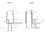
- Figure 5a shows in cross section the first tray 1 stacked on top of the second tray 1a.
- the tab 15 of the first tray 1 is in the first position so that the end of the leg 10 of the second tray 1 a rests on the slideable cover 25 closing the aperture 20 in the deck 2 of the first tray 1.
- Figure 5b shows the situation when the tab 15 of the first tray 1 is in the second position and the leg of the second tray 1a is partly inserted into the inside of the leg 10 of the first tray 1.
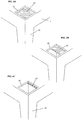
- Figure 6A shows a view of the underside of the tray 1, showing the aperture 20 in the deck 2 and the slideable cover 25 that closes the aperture 20 when the tab 15 is in the first position.
- the cover 25 is slightly below the underside surface of the deck 2 providing a small recess in which the end of a leg 10 of another tray may be located.
- the cover 25 and aperture 20 may instead be flush with the surface of the deck 2.
- Figure 6B is a similar view to figure 6A but shows the position of the cover 25 when the tab 15 is partly between the first and second position.
- Figure 6C shows the exposed aperture 20 in the deck 2 with the cover 25 fully drawn back when the tab 15 is moved to the second position. By moving the cover 25 and exposing the aperture 20 the hollow inside of the leg 10 can be accessed.
- Figures 6B and 6C show that the covers 25 slide linearly so as to move in a plane parallel to the deck 2.
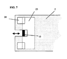
- Figure 7 shows the underside of the deck 2 in plan view.
- the tab 15 is shown partly between the first position and the second position.
- the slideable cover 25 has exposed part of the aperture 20 in the deck 2.
- the embodiments described above provide the advantage that by allowing the legs of one tray to be partly accommodated inside the legs of another tray, the trays may be stacked in a nested fashion.
- the space required for storage is greatly reduced.
- the space required for four trays stacked in a nested manner may be less than the space required for two trays in an un-nested stack.
- the space saving may be 30% and possibly 50% or more.
- tabs 15 may be pushed in it is easy to operate the opening of the apertures 20 in the deck 2 to allow nesting. It is also possible that only one tab 15 is provided that opens and closes all the apertures in the deck allowing easy operation and allowing the nesting operation to be carried out efficiently and quickly.
Landscapes
- Engineering & Computer Science (AREA)
- Mechanical Engineering (AREA)
- Stackable Containers (AREA)
- Pallets (AREA)
- Physical Or Chemical Processes And Apparatus (AREA)
Abstract
Description
- The present invention relates to a tray used for loading with a product. More particularly the present invention relates to a tray having legs that enable a number of trays to be stacked on top of each other.
- Conventional trays that are typically made from wood, metal or plastic and can only be placed on top of each other in a stacked formation. The trays cannot usually be stored in a more space efficient manner and thus, when the trays are stored they take up large amounts of space leading to high transportation and storage costs.
- There is a need for a tray that can be stacked on top of another tray when needed, i.e. when holding products, but which is also able to be stored in a more space efficient manner when riot being used.
-
EP-A-0 726 206 describes an article for handling products comprising a base, a plurality of hollow legs arranged so as to allow nesting of a second tray. The apertures of the hollow legs are associated with a plurality of covers that are rotatable about an axis parallel to the base to cover the apertures. -
DE 44 38 983 describes a container comprising a slidable element which can be arranged in a first position, in which the container is nestable, and a second position, in which the container is stackable. - The present invention has been made with the aim of solving the above problems.
- In accordance with the invention, there is provided a tray as defined in the claims.
- Preferred embodiments of the invention will now be described, by way of example only, with reference to the accompanying drawings.
-
-
Figure 1 is a perspective view of a tray in accordance with a preferred embodiment of the invention. -
Figure 2 is a perspective view of a number of trays stacked on top of one another in accordance with the preferred embodiment. -
Figure 3 is a perspective view of the tray of the preferred embodiment with its tabs pushed inwards. -
Figure 4 is a perspective view of a number of the trays stored in a nested fashion in accordance with the preferred embodiment. -
Figures 5A and 5B are cross sectional views of the hollow legs in accordance with the preferred embodiment. -
Figures 6A to 6C are perspective views of the underside of the tray in accordance with the preferred embodiment. -
Figure 7 is a plan view of the underside of the tray showing the arrangement of a movable cover, tabs and apertures in accordance with the preferred embodiment. - The embodiments described below are in relation to a typical arrangement for a nested tray, although it will be appreciated that other embodiments will fall within the scope of the appended claims.
-
Figure 1 shows atray 1 that includes adeck 2 and a plurality oflegs 10 attached thereto that project to one side of thedeck 2. Thelegs 10 are preferably tapered and are placed at the corners of thedeck 2. Although not shown, the legs are hollow. Thetray 1 is typically made from a plastics material, although it may be made from any other suitable material, such as metal. Thedeck 1 andlegs 10, if made from a plastics material, may be formed by injection moulding. Alternatively, thedeck 2 andlegs 10 may be separately formed and thelegs 10 affixed to thedeck 2. Although thetray 1 is shown having fourlegs 10, the number of legs is not limited to this; there may typically be three or more legs. Thetray 1 also includes at least onemoveable tab 15. The number oftabs 15 is shown as two, but it should be understood that it is not limited to this number, there may be one or more tabs, although there will usually be no more tabs than the number of legs. Thetabs 15 are operable to move from a first, outer position, to a second, inner position. Changing the position of thetabs 15 allows the trays to either be stacked on top of each other or stored in a space saving manner. The operation of thetabs 15 will be described in more detail below. -
Figure 2 shows thefirst tray 1 stacked on top of a second tray 1a when thetabs 15 are in the first position. With reference toFig. 6A , thedeck 2 has a plurality ofapertures 20 in its underside, one for each leg, and when thetabs 15 are in the first position, slideable covers 25 close the apertures. This allows the trays to be stacked on top of each other. Preferably theslideable cover 25 is indented from the underside surface of thedeck 2 and forms an indentation in which the ends of thelegs 10 may be accommodated. Such an arrangement allows the trays to be stacked more securely. -
Figure 3 shows thefirst tray 1 with thetabs 15 in the second position. By pushing thetabs 15 in to their second position, theslideable covers 25 are moved so as to reveal theapertures 20 in the deck 2 (seeFig. 6C ). Theapertures 20 are arranged and positioned in the deck to correspond to the inside of thehollow legs 10. - As shown in
Figure 4 , by moving thetabs 15 to their second position, thus opening theapertures 20 in thedeck 2, the legs of a second tray 1a are able to be partly inserted into the inside of the legs of thefirst tray 1. Any number of trays can be nested and stored in this manner, as shown by athird tray 1b, the legs of which are partly accommodated by the legs of the second tray 1a. -
Figure 5a shows in cross section thefirst tray 1 stacked on top of the second tray 1a. Thetab 15 of thefirst tray 1 is in the first position so that the end of theleg 10 of the second tray 1 a rests on theslideable cover 25 closing theaperture 20 in thedeck 2 of thefirst tray 1.Figure 5b shows the situation when thetab 15 of thefirst tray 1 is in the second position and the leg of the second tray 1a is partly inserted into the inside of theleg 10 of thefirst tray 1. -
Figure 6A shows a view of the underside of thetray 1, showing theaperture 20 in thedeck 2 and theslideable cover 25 that closes theaperture 20 when thetab 15 is in the first position. As can be seen inFigure 6a thecover 25 is slightly below the underside surface of thedeck 2 providing a small recess in which the end of aleg 10 of another tray may be located. However, it is not necessary for thecover 25 andaperture 20 to form a recess; thecover 25 may instead be flush with the surface of thedeck 2. -
Figure 6B is a similar view tofigure 6A but shows the position of thecover 25 when thetab 15 is partly between the first and second position. -
Figure 6C shows the exposedaperture 20 in thedeck 2 with thecover 25 fully drawn back when thetab 15 is moved to the second position. By moving thecover 25 and exposing theaperture 20 the hollow inside of theleg 10 can be accessed.Figures 6B and 6C show that the covers 25 slide linearly so as to move in a plane parallel to thedeck 2. -
Figure 7 shows the underside of thedeck 2 in plan view. Thetab 15 is shown partly between the first position and the second position. As can be seen theslideable cover 25 has exposed part of theaperture 20 in thedeck 2. - The embodiments described above provide the advantage that by allowing the legs of one tray to be partly accommodated inside the legs of another tray, the trays may be stacked in a nested fashion. In the nested fashion the space required for storage is greatly reduced. For example the space required for four trays stacked in a nested manner may be less than the space required for two trays in an un-nested stack. The space saving may be 30% and possibly 50% or more.
- In addition because the
tabs 15 may be pushed in it is easy to operate the opening of theapertures 20 in thedeck 2 to allow nesting. It is also possible that only onetab 15 is provided that opens and closes all the apertures in the deck allowing easy operation and allowing the nesting operation to be carried out efficiently and quickly. - Although the present invention has been described in terms of preferred embodiments, it will be appreciable that various modifications and alterations might be made by those skilled in the art without departing from the scope of the invention. The invention should therefore be measured in terms of the claims which follow.
Claims (6)
- A tray (1) comprising
a deck (2),
a plurality of legs (10) projecting to one side of the deck (2),
a plurality of apertures (20) formed in the other side of the deck (2) and being arranged to allow passage of the legs of a second tray (1a, 1b) so that said trays may be stacked in a nested fashion, and
a plurality of movable covers (25) associated with the plurality of apertures (20), said covers being movable to selectively cover or open the plurality of apertures (20), characterised in that the covers (25) are slideable to selectively cover or open the plurality of apertures (20), the tray further comprising
at least one tab (15) connected to the plurality of slideable covers (25), the at least one tab (15) being selectively movable from a first position to a second position, wherein in the first position of the at least one tab (15) the plurality of slideable covers (25) cover the plurality of apertures (20) and wherein in the second position of the at least one tab (15) the plurality of movable covers (25) do not cover the plurality of apertures (20). - A tray (1) according to claim 1, wherein the plurality of legs (10) are hollow to allow insertion of the legs of the second tray.
- A tray (1) according to any preceding claim, wherein the plurality of legs (10) are tapered.
- A tray according to any preceding claim, wherein the plurality of movable covers (25) and the deck (2) are arranged such that when the plurality of covers (25) cover the plurality of apertures (20) recesses are formed between the surface on said other side of the deck (2) and the plurality of moveable covers (25) to accept the ends of the plurality of legs of the second tray to allow un-nested stacking.
- A tray according to any of claims 1 to 3, wherein the plurality of movable covers. (25) and the deck (2) are constructed and arranged such that when the plurality of covers (25) cover the plurality of apertures (20) the plurality of covers (25) are flush with the surface on said other side of the deck (2) to allow un-nested stacking.
- A tray according to any preceding claim, wherein the deck (2) and the plurality of legs (10) are formed by injection moulding.
Applications Claiming Priority (1)
| Application Number | Priority Date | Filing Date | Title |
|---|---|---|---|
| GB0713620A GB2450928A (en) | 2007-07-12 | 2007-07-12 | Stackable and nestable tray |
Publications (2)
| Publication Number | Publication Date |
|---|---|
| EP2014561A1 EP2014561A1 (en) | 2009-01-14 |
| EP2014561B1 true EP2014561B1 (en) | 2011-09-14 |
Family
ID=38461528
Family Applications (1)
| Application Number | Title | Priority Date | Filing Date |
|---|---|---|---|
| EP08252391A Active EP2014561B1 (en) | 2007-07-12 | 2008-07-14 | Stacking or nesting tray |
Country Status (3)
| Country | Link |
|---|---|
| EP (1) | EP2014561B1 (en) |
| AT (1) | ATE524388T1 (en) |
| GB (1) | GB2450928A (en) |
Cited By (1)
| Publication number | Priority date | Publication date | Assignee | Title |
|---|---|---|---|---|
| EP4082928A1 (en) | 2021-04-26 | 2022-11-02 | Schoeller Allibert GmbH | Stackable and nestable container |
Family Cites Families (8)
| Publication number | Priority date | Publication date | Assignee | Title |
|---|---|---|---|---|
| NL99987C (en) * | 1958-02-03 | |||
| GB1148535A (en) * | 1966-09-29 | 1969-04-16 | Shaw Regent Ltd | Storage racks |
| DE4438983A1 (en) | 1994-10-31 | 1996-05-02 | Thyssen Polymer Gmbh | Container with symmetrical ribs for stacking |
| FR2730215A1 (en) | 1995-02-08 | 1996-08-09 | Allibert Equipement | HANDPIECE OF THE EMBOITABLE OR SUPERPOSABLE TYPE |
| GB9625333D0 (en) * | 1996-12-05 | 1997-01-22 | Lin Pac Mouldings | A container |
| US6327984B1 (en) * | 2000-06-15 | 2001-12-11 | U.S. Plastic Lumber | Nestable shipping pallet with adjustable deck |
| US6510801B2 (en) * | 2001-06-01 | 2003-01-28 | Hong Sin Tan | Pallet for shrinkwrapped packaging of block rubber |
| GB2414464A (en) * | 2004-05-25 | 2005-11-30 | Linpac Mouldings Ltd | Pallet with closures for leg apertures |
-
2007
- 2007-07-12 GB GB0713620A patent/GB2450928A/en not_active Withdrawn
-
2008
- 2008-07-14 EP EP08252391A patent/EP2014561B1/en active Active
- 2008-07-14 AT AT08252391T patent/ATE524388T1/en not_active IP Right Cessation
Cited By (3)
| Publication number | Priority date | Publication date | Assignee | Title |
|---|---|---|---|---|
| EP4082928A1 (en) | 2021-04-26 | 2022-11-02 | Schoeller Allibert GmbH | Stackable and nestable container |
| WO2022228810A1 (en) | 2021-04-26 | 2022-11-03 | Schoeller Allibert Gmbh | Stackable and nestable container |
| US12492040B2 (en) | 2021-04-26 | 2025-12-09 | Schoeller Allibert Gmbh | Stackable and nestable container |
Also Published As
| Publication number | Publication date |
|---|---|
| GB2450928A (en) | 2009-01-14 |
| GB0713620D0 (en) | 2007-08-22 |
| EP2014561A1 (en) | 2009-01-14 |
| ATE524388T1 (en) | 2011-09-15 |
Similar Documents
| Publication | Publication Date | Title |
|---|---|---|
| US5123564A (en) | Compartmented storage container | |
| US9272812B2 (en) | Octagonal container and pallet therefor | |
| CN102548854B (en) | Flexibly usable box | |
| EP2688808B1 (en) | Three tiered tray | |
| US7823728B2 (en) | Storage container with support structure for multiple levels of nesting | |
| US11174070B2 (en) | Stackable pallet | |
| US10654618B2 (en) | Bulk container with interlocking features | |
| US6349656B1 (en) | Nestable containment tray for a hazardous material spill pallet | |
| US11827444B2 (en) | Nesting packaging design for planters | |
| US20160272369A1 (en) | Containing Box Structure | |
| US12623810B2 (en) | Plastic pallet | |
| JP3200776U (en) | Food packaging container | |
| EP2014561A1 (en) | Stacking or nesting tray | |
| US20050000847A1 (en) | Baked goods container | |
| US20040163971A1 (en) | Modular container | |
| US20170081077A1 (en) | A Lid and a Storage System | |
| JP2017149462A (en) | Food packaging container | |
| US20070095695A1 (en) | Card file | |
| CA2866924C (en) | Multi-level stacking container | |
| GB2423983A (en) | A nest- and stackable storage container | |
| JP7423045B2 (en) | palette | |
| US12492040B2 (en) | Stackable and nestable container | |
| JPH0120254Y2 (en) | ||
| KR200310993Y1 (en) | Assembly drawer | |
| US12391434B1 (en) | Storage compartment box with self-aligning bins |
Legal Events
| Date | Code | Title | Description |
|---|---|---|---|
| PUAI | Public reference made under article 153(3) epc to a published international application that has entered the european phase |
Free format text: ORIGINAL CODE: 0009012 |
|
| AK | Designated contracting states |
Kind code of ref document: A1 Designated state(s): AT BE BG CH CY CZ DE DK EE ES FI FR GB GR HR HU IE IS IT LI LT LU LV MC MT NL NO PL PT RO SE SI SK TR |
|
| AX | Request for extension of the european patent |
Extension state: AL BA MK RS |
|
| 17P | Request for examination filed |
Effective date: 20090713 |
|
| AKX | Designation fees paid |
Designated state(s): AT BE BG CH CY CZ DE DK EE ES FI FR GB GR HR HU IE IS IT LI LT LU LV MC MT NL NO PL PT RO SE SI SK TR |
|
| 17Q | First examination report despatched |
Effective date: 20100625 |
|
| RIC1 | Information provided on ipc code assigned before grant |
Ipc: B65D 21/06 20060101AFI20110124BHEP |
|
| GRAP | Despatch of communication of intention to grant a patent |
Free format text: ORIGINAL CODE: EPIDOSNIGR1 |
|
| RIN1 | Information on inventor provided before grant (corrected) |
Inventor name: LOFTUS, STEVE |
|
| GRAS | Grant fee paid |
Free format text: ORIGINAL CODE: EPIDOSNIGR3 |
|
| GRAA | (expected) grant |
Free format text: ORIGINAL CODE: 0009210 |
|
| AK | Designated contracting states |
Kind code of ref document: B1 Designated state(s): AT BE BG CH CY CZ DE DK EE ES FI FR GB GR HR HU IE IS IT LI LT LU LV MC MT NL NO PL PT RO SE SI SK TR |
|
| REG | Reference to a national code |
Ref country code: GB Ref legal event code: FG4D |
|
| REG | Reference to a national code |
Ref country code: CH Ref legal event code: EP |
|
| REG | Reference to a national code |
Ref country code: IE Ref legal event code: FG4D |
|
| REG | Reference to a national code |
Ref country code: DE Ref legal event code: R096 Ref document number: 602008009761 Country of ref document: DE Effective date: 20111110 |
|
| REG | Reference to a national code |
Ref country code: NL Ref legal event code: VDEP Effective date: 20110914 |
|
| PG25 | Lapsed in a contracting state [announced via postgrant information from national office to epo] |
Ref country code: SE Free format text: LAPSE BECAUSE OF FAILURE TO SUBMIT A TRANSLATION OF THE DESCRIPTION OR TO PAY THE FEE WITHIN THE PRESCRIBED TIME-LIMIT Effective date: 20110914 Ref country code: HR Free format text: LAPSE BECAUSE OF FAILURE TO SUBMIT A TRANSLATION OF THE DESCRIPTION OR TO PAY THE FEE WITHIN THE PRESCRIBED TIME-LIMIT Effective date: 20110914 Ref country code: FI Free format text: LAPSE BECAUSE OF FAILURE TO SUBMIT A TRANSLATION OF THE DESCRIPTION OR TO PAY THE FEE WITHIN THE PRESCRIBED TIME-LIMIT Effective date: 20110914 Ref country code: NO Free format text: LAPSE BECAUSE OF FAILURE TO SUBMIT A TRANSLATION OF THE DESCRIPTION OR TO PAY THE FEE WITHIN THE PRESCRIBED TIME-LIMIT Effective date: 20111214 Ref country code: LT Free format text: LAPSE BECAUSE OF FAILURE TO SUBMIT A TRANSLATION OF THE DESCRIPTION OR TO PAY THE FEE WITHIN THE PRESCRIBED TIME-LIMIT Effective date: 20110914 |
|
| LTIE | Lt: invalidation of european patent or patent extension |
Effective date: 20110914 |
|
| PG25 | Lapsed in a contracting state [announced via postgrant information from national office to epo] |
Ref country code: CY Free format text: LAPSE BECAUSE OF FAILURE TO SUBMIT A TRANSLATION OF THE DESCRIPTION OR TO PAY THE FEE WITHIN THE PRESCRIBED TIME-LIMIT Effective date: 20110914 Ref country code: AT Free format text: LAPSE BECAUSE OF FAILURE TO SUBMIT A TRANSLATION OF THE DESCRIPTION OR TO PAY THE FEE WITHIN THE PRESCRIBED TIME-LIMIT Effective date: 20110914 Ref country code: LV Free format text: LAPSE BECAUSE OF FAILURE TO SUBMIT A TRANSLATION OF THE DESCRIPTION OR TO PAY THE FEE WITHIN THE PRESCRIBED TIME-LIMIT Effective date: 20110914 Ref country code: SI Free format text: LAPSE BECAUSE OF FAILURE TO SUBMIT A TRANSLATION OF THE DESCRIPTION OR TO PAY THE FEE WITHIN THE PRESCRIBED TIME-LIMIT Effective date: 20110914 Ref country code: GR Free format text: LAPSE BECAUSE OF FAILURE TO SUBMIT A TRANSLATION OF THE DESCRIPTION OR TO PAY THE FEE WITHIN THE PRESCRIBED TIME-LIMIT Effective date: 20111215 |
|
| REG | Reference to a national code |
Ref country code: AT Ref legal event code: MK05 Ref document number: 524388 Country of ref document: AT Kind code of ref document: T Effective date: 20110914 |
|
| PG25 | Lapsed in a contracting state [announced via postgrant information from national office to epo] |
Ref country code: BE Free format text: LAPSE BECAUSE OF FAILURE TO SUBMIT A TRANSLATION OF THE DESCRIPTION OR TO PAY THE FEE WITHIN THE PRESCRIBED TIME-LIMIT Effective date: 20110914 |
|
| PG25 | Lapsed in a contracting state [announced via postgrant information from national office to epo] |
Ref country code: CZ Free format text: LAPSE BECAUSE OF FAILURE TO SUBMIT A TRANSLATION OF THE DESCRIPTION OR TO PAY THE FEE WITHIN THE PRESCRIBED TIME-LIMIT Effective date: 20110914 Ref country code: IS Free format text: LAPSE BECAUSE OF FAILURE TO SUBMIT A TRANSLATION OF THE DESCRIPTION OR TO PAY THE FEE WITHIN THE PRESCRIBED TIME-LIMIT Effective date: 20120114 Ref country code: SK Free format text: LAPSE BECAUSE OF FAILURE TO SUBMIT A TRANSLATION OF THE DESCRIPTION OR TO PAY THE FEE WITHIN THE PRESCRIBED TIME-LIMIT Effective date: 20110914 |
|
| PG25 | Lapsed in a contracting state [announced via postgrant information from national office to epo] |
Ref country code: PT Free format text: LAPSE BECAUSE OF FAILURE TO SUBMIT A TRANSLATION OF THE DESCRIPTION OR TO PAY THE FEE WITHIN THE PRESCRIBED TIME-LIMIT Effective date: 20120116 Ref country code: IT Free format text: LAPSE BECAUSE OF FAILURE TO SUBMIT A TRANSLATION OF THE DESCRIPTION OR TO PAY THE FEE WITHIN THE PRESCRIBED TIME-LIMIT Effective date: 20110914 Ref country code: NL Free format text: LAPSE BECAUSE OF FAILURE TO SUBMIT A TRANSLATION OF THE DESCRIPTION OR TO PAY THE FEE WITHIN THE PRESCRIBED TIME-LIMIT Effective date: 20110914 Ref country code: PL Free format text: LAPSE BECAUSE OF FAILURE TO SUBMIT A TRANSLATION OF THE DESCRIPTION OR TO PAY THE FEE WITHIN THE PRESCRIBED TIME-LIMIT Effective date: 20110914 Ref country code: EE Free format text: LAPSE BECAUSE OF FAILURE TO SUBMIT A TRANSLATION OF THE DESCRIPTION OR TO PAY THE FEE WITHIN THE PRESCRIBED TIME-LIMIT Effective date: 20110914 Ref country code: RO Free format text: LAPSE BECAUSE OF FAILURE TO SUBMIT A TRANSLATION OF THE DESCRIPTION OR TO PAY THE FEE WITHIN THE PRESCRIBED TIME-LIMIT Effective date: 20110914 |
|
| PLBE | No opposition filed within time limit |
Free format text: ORIGINAL CODE: 0009261 |
|
| STAA | Information on the status of an ep patent application or granted ep patent |
Free format text: STATUS: NO OPPOSITION FILED WITHIN TIME LIMIT |
|
| PG25 | Lapsed in a contracting state [announced via postgrant information from national office to epo] |
Ref country code: DK Free format text: LAPSE BECAUSE OF FAILURE TO SUBMIT A TRANSLATION OF THE DESCRIPTION OR TO PAY THE FEE WITHIN THE PRESCRIBED TIME-LIMIT Effective date: 20110914 |
|
| 26N | No opposition filed |
Effective date: 20120615 |
|
| REG | Reference to a national code |
Ref country code: DE Ref legal event code: R097 Ref document number: 602008009761 Country of ref document: DE Effective date: 20120615 |
|
| PGFP | Annual fee paid to national office [announced via postgrant information from national office to epo] |
Ref country code: DE Payment date: 20120829 Year of fee payment: 5 |
|
| PG25 | Lapsed in a contracting state [announced via postgrant information from national office to epo] |
Ref country code: MC Free format text: LAPSE BECAUSE OF NON-PAYMENT OF DUE FEES Effective date: 20120731 |
|
| REG | Reference to a national code |
Ref country code: CH Ref legal event code: PL |
|
| REG | Reference to a national code |
Ref country code: FR Ref legal event code: ST Effective date: 20130329 |
|
| PG25 | Lapsed in a contracting state [announced via postgrant information from national office to epo] |
Ref country code: CH Free format text: LAPSE BECAUSE OF NON-PAYMENT OF DUE FEES Effective date: 20120731 Ref country code: LI Free format text: LAPSE BECAUSE OF NON-PAYMENT OF DUE FEES Effective date: 20120731 Ref country code: ES Free format text: LAPSE BECAUSE OF FAILURE TO SUBMIT A TRANSLATION OF THE DESCRIPTION OR TO PAY THE FEE WITHIN THE PRESCRIBED TIME-LIMIT Effective date: 20111225 Ref country code: FR Free format text: LAPSE BECAUSE OF NON-PAYMENT OF DUE FEES Effective date: 20120731 |
|
| REG | Reference to a national code |
Ref country code: IE Ref legal event code: MM4A |
|
| PG25 | Lapsed in a contracting state [announced via postgrant information from national office to epo] |
Ref country code: BG Free format text: LAPSE BECAUSE OF FAILURE TO SUBMIT A TRANSLATION OF THE DESCRIPTION OR TO PAY THE FEE WITHIN THE PRESCRIBED TIME-LIMIT Effective date: 20111214 |
|
| PG25 | Lapsed in a contracting state [announced via postgrant information from national office to epo] |
Ref country code: IE Free format text: LAPSE BECAUSE OF NON-PAYMENT OF DUE FEES Effective date: 20120714 Ref country code: MT Free format text: LAPSE BECAUSE OF FAILURE TO SUBMIT A TRANSLATION OF THE DESCRIPTION OR TO PAY THE FEE WITHIN THE PRESCRIBED TIME-LIMIT Effective date: 20110914 |
|
| REG | Reference to a national code |
Ref country code: DE Ref legal event code: R119 Ref document number: 602008009761 Country of ref document: DE Effective date: 20140201 |
|
| PG25 | Lapsed in a contracting state [announced via postgrant information from national office to epo] |
Ref country code: DE Free format text: LAPSE BECAUSE OF NON-PAYMENT OF DUE FEES Effective date: 20140201 Ref country code: TR Free format text: LAPSE BECAUSE OF FAILURE TO SUBMIT A TRANSLATION OF THE DESCRIPTION OR TO PAY THE FEE WITHIN THE PRESCRIBED TIME-LIMIT Effective date: 20110914 |
|
| PG25 | Lapsed in a contracting state [announced via postgrant information from national office to epo] |
Ref country code: LU Free format text: LAPSE BECAUSE OF NON-PAYMENT OF DUE FEES Effective date: 20120714 |
|
| PG25 | Lapsed in a contracting state [announced via postgrant information from national office to epo] |
Ref country code: HU Free format text: LAPSE BECAUSE OF FAILURE TO SUBMIT A TRANSLATION OF THE DESCRIPTION OR TO PAY THE FEE WITHIN THE PRESCRIBED TIME-LIMIT Effective date: 20080714 |
|
| REG | Reference to a national code |
Ref country code: GB Ref legal event code: 732E Free format text: REGISTERED BETWEEN 20170511 AND 20170517 |
|
| PGFP | Annual fee paid to national office [announced via postgrant information from national office to epo] |
Ref country code: GB Payment date: 20250724 Year of fee payment: 18 |