EP2014223B1 - Optisches Messsystem für lebende Körper - Google Patents
Optisches Messsystem für lebende Körper Download PDFInfo
- Publication number
- EP2014223B1 EP2014223B1 EP08011379.8A EP08011379A EP2014223B1 EP 2014223 B1 EP2014223 B1 EP 2014223B1 EP 08011379 A EP08011379 A EP 08011379A EP 2014223 B1 EP2014223 B1 EP 2014223B1
- Authority
- EP
- European Patent Office
- Prior art keywords
- light
- series
- code
- codes
- living body
- Prior art date
- Legal status (The legal status is an assumption and is not a legal conclusion. Google has not performed a legal analysis and makes no representation as to the accuracy of the status listed.)
- Ceased
Links
- 0 C*S(C)C1C(C)C*(C)C1 Chemical compound C*S(C)C1C(C)C*(C)C1 0.000 description 1
Images


Classifications
-
- A—HUMAN NECESSITIES
- A61—MEDICAL OR VETERINARY SCIENCE; HYGIENE
- A61B—DIAGNOSIS; SURGERY; IDENTIFICATION
- A61B5/00—Measuring for diagnostic purposes; Identification of persons
- A61B5/145—Measuring characteristics of blood in vivo, e.g. gas concentration or pH-value ; Measuring characteristics of body fluids or tissues, e.g. interstitial fluid or cerebral tissue
- A61B5/1455—Measuring characteristics of blood in vivo, e.g. gas concentration or pH-value ; Measuring characteristics of body fluids or tissues, e.g. interstitial fluid or cerebral tissue using optical sensors, e.g. spectral photometrical oximeters
- A61B5/14551—Measuring characteristics of blood in vivo, e.g. gas concentration or pH-value ; Measuring characteristics of body fluids or tissues, e.g. interstitial fluid or cerebral tissue using optical sensors, e.g. spectral photometrical oximeters for measuring blood gases
- A61B5/14553—Measuring characteristics of blood in vivo, e.g. gas concentration or pH-value ; Measuring characteristics of body fluids or tissues, e.g. interstitial fluid or cerebral tissue using optical sensors, e.g. spectral photometrical oximeters for measuring blood gases specially adapted for cerebral tissue
Definitions
- the present invention relates to a living body optical measurement system, or a living body optical measurement system for optically measuring information within a living body.
- a device for measuring easily the inside of living body without causing damages to the living body is hoped for in such fields as clinical medicine, brain science and the like.
- brain diseases such as cerebral infarction, brain hemorrhage, etc. and high-order brain functions such as thinking, language, physical exercise and the like are mentioned.
- subjects of measurement are not limited to the head, but also preventive diagnosis relating to heart diseases such as cardiac infarction and the chest region, visceral diseases of the kidney, liver and the like in the abdomen are mentioned.
- heart diseases such as cardiac infarction and the chest region, visceral diseases of the kidney, liver and the like in the abdomen are mentioned.
- the head is considered as the subject of measurement and diseases in the brain or high-order brain functions are measured, it is necessary to clearly specify the involved area or the functional region. For this reason, it is very important to measure a wide area of the head as an image.
- optical measurements are very effective, because the normal and abnormal state of living body organs and the activation of the brain relating to high-order brain functions are closely related with the oxygen metabolism and blood volume within the living body.
- oxygen metabolism and blood volume correspond to the density of specific pigments (hemoglobin, cytochrome aa3, myoglobin, etc.) in living body, and this pigment density is calculated by the amount of light absorption in the visual - infrared wavelength range.
- JP-A-Sho57(1982)-115232 JP-A-Sho63(1988)-260532 , JP-A-Sho63(1988)-275323 and JP-A-Hei5(1993)-317295 .
- time-division multiplex modulation system frequency multiplexing system and the like among light-intensity modulation systems have been used for the measurement of light in living body.
- the basic structure is that of deriving intensity data by means of optical detection with the help of a lock-in amplifier, and time-division multiplexing or frequency multiplexing has been adopted to increase points of measurement.
- CDMA code division multiplex access
- US 2006/222224 A1 and JP 2006 230657 A disclose biologi cal information measurement devices with the features in the pre-characterising portion of claim 1.
- Fig. 1 shows the outline of a device using the conventional CDMA modulation system.
- Light irradiation de vices 101, 102, and 103 include respectively a code generating unit 111, 121, and 131, a light modulating unit 112, 122 an 132, a light irradiating unit 113, 123 and 133.
- the code generating unit 111, 121 and 131 generate respectively circulating code series C1 "1, 0, 1, 0", C2 "1, 0, 1, 0", and C3 "1, 0, 1, 0."
- the light modulating unit 112, 122, and 132 generates codes subjected to intensity modulation by the code series C1, C2 and C3.
- the codes subjected to intensity modulation blink the light source elements 114, 124 and 134 of the light irradiating units 113, 123 and 133.
- the light source lights up when its code series C1, C2 and C3 are in position "1" and goes out when its code series C1, C2 and C3 are in position "0.”
- the light (emitted light) emitted from the ligh source elements 114, 124 and 134 is irradiated on the subject of irradiation as optical signals at the irradiation positions 115, 125 and 135.
- the respective irradiated light reaches the light-sensitive element 117 of the light detecting unit 116 after transmitting/diffusing in the living body which is the subject of irradiation.
- the optical signal is converted into electrical signal by photoelectric effect.
- This electrical signal is divided into three signals, and the series C' 1, C' 2 and C'3 synchronized with the original series are multiplied by three multiplier circuits 118 in the signal processing unit 119.
- the series C'1, C' 2 and C' 3 are series generated by the modulation code generating unit 151, 152 and 153.
- the correlation detecting unit 140 detects the correlation of the respective result of multiplication and outputs the correlation detection outputs which are detection results 141, 142 and 143.
- CDMA modulation codes are a signal system called Hadamard codes (Walsh-Hadamard codes).
- This code system is characterized by (1) an outstanding correlativity of being able to completely remove other series of codes which are also Hadamard codes, and (2) an equal number of "1" and "0" constituting the codes resulting in a duty ratio of codes of 50%.
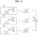
- Fig. 2 shows the signals that enter light sensitive elements.
- the light sensitive elements receive the input of three lights in a mixed form by the addition effect 201.
- the difference of amplitude of signals inputted into the light sensitive elements (illustration omitted) depending on the irradiation position 115, 125 and 135 in Fig. 2 is due to the difference of the driving current of the light sensitive elements and the difference of transmission/diffusion characteristics of light between various irradiation positions 115, 125, and 135 and the light sensitive element.
- the output of light sensitive elements is proportional to the result of addition of input light of Fig. 2 .
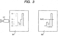
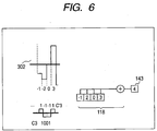
- the codes "6, 3, 1, 2" in time series are outputted in a cyclical form (6, 3, 1, 2, 6, 3, 1, 2, ). Since each code has a duty ratio of 50%, the result of addition is 3 in average. If an AC coupling process is carried out in the actual circuit, the light-receiving signal 302 of "3, 0, -2, -1" in time series with the value 3 before the coupling as its center are outputted in a cyclical form.
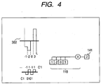
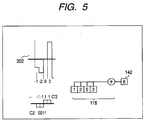
- the AC-coupled light-receiving signals 302, in other word "3, 0, -2, -1" is multiplied in a synchronized form by the series C'1 "1, -1. 1. -1" obtained by implementing a conversion defined by the multiplication by 2 of and the subtraction of 1 from each value of the code series C1 "1, 0, 1, 0" used at the time of generating the original code, and then the result is added for each 4 bits, and is outputted as the detection result.
- the term "synchronized” means that the correspondence and variation points of a certain value "1" and "0" of the series C1 mentioned above and the value "1" or "-1" by the conversion mentioned above corresponding thereto are the same on the time axis.
- signals are subjected to a modulation of intensity, optical signals are transmitted and post-photoelectric conversion signals are demodulated by using the CDMA method in the device to measure the activity of the living body serving as the transmission route of light.
- the processing unit for demodulating CDMA must receive light, carry out photoelectric conversion and process signals of the maximum level "6" at a level that avoids their saturation.
- This point increases in the same way as the driving current mentioned above as the number of light sources, in other words, measuring points and irradiation positions increases.
- the present invention reduces the peak value of the driving current of light-sensitive elements and light receiving signals by changing the position of two or more signals on the time axis in the living body optical measurement system using the CDMA codes.
- codes of which bits are shifted by the same bit for each code series having the same bit cycle as Hadamard code, or codes of which bits are shifted by a PN code are used as different codes.
- the present invention it is possible to make the peak value smaller than the conventional one by smoothing the driving current of light-sensitive elements in the living body optical measuring system using the CDMA codes, and to make the peak value of light receiving level of light-sensitive elements smaller than the conventional ones. In this way, it is possible to save power consumption of the living body optical measurement system and to improve the precision of measurement.
- bit cycle a is the minimum value of natural number for which the following equation (5) is valid for an arbitrary n1 or n2.
- Series C1 of Table 1 corresponds to bit cycle 2 and series C2 and series C3 correspond to bit cycle 4.
- the series of the same bit cycle is considered as a bit cycle group, and we will call them bit cycle a group.
- series C2 and series C3 correspond to the bit cycle 4 and are represented by the bit cycle 4 group.
- the bit cycle 4 group represents series C2 and series C3.
- the bit bn is a binary data constituted by "1” or "0", and according to the configuration shown in Fig. 1 , in the case of "1" the light-sensitive elements light up and in the case of "0" they go out.
- the total shows the number of light-sensitive elements that light up at the time at which each bit bn corresponds.
- Table 2 is similar but the bits have shifted.
- C"1 for which b"(1) - (4) are shown by “0, 1, 0, 1” has C1 shifted by one bit forward (or backward).
- C"2 shown by “0, 0, 1, 1” has “1, 1, 0, 0” C2 shifted by two bits.
- C"3 shown by “0, 1, 1, 0” has “1, 0, 0, 1” C3 shifted by two bits.
- codes of the same bit cycle group are separated by the amount of phase deviation for the same bit cycle thereof.
- the information for separation is contained in each code (each series) in the form of phase information.
- both C2 and C3 belong to the bit cycle 4 group, and they are separated at the time of their detection by the phase information of C2 and C3.
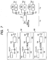
- Fig. 7 shows an overview of a device made by using the new Hadamard series. This corresponds to Fig. 1 used for the description of a device made by using the conventional Hadamard series.
- the difference with the device shown in Fig. 1 lies in that the code series generated by the code generators 711, 721 and 731 are the new Hadamard series C"1, C"2 and C"3, and that the demodulation codes generated by the demodulation code generating units 751, 752 and 753 are codes for the demodulation of the new Hadamard series.
- the respective correlation detecting unit 140 outputs the detection results 741, 742 and 742 in the new Hadamard series C"1, C"2 and C"3.
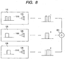
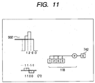
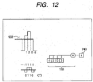
- Fig. 8 shows signals emitted from the light source elements
- Fig. 9 shows signals received by the light-sensitive elements.
- the codes at each irradiation position in Fig. 8 are outputted by the sequential order from the right side of the figure, For example, in the case of irradiation position 115, they are outputted in the order of "0, 1, 0, 1.”
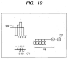
- the aggregate total of light receiving signal 901 in the case where this new Hadamard series is applied revolves in time series order of "0, 3, 5, 4.”
- the AC coupled light receiving signals 902 in the case where the new Hadamard series is applied revolves in the order of "-3, 0, 2, 1. "
- the Hadamard codes for the code.
- M series and Gold series which are widely known PN code series other than the Hadamard codes
- M series a type of series is bit shifted and is handled as separatable code (subject to demodulation/detection).
- the PN code is also called "pseudonoise code” and refers to the whole cyclical code wherein the code spectrum has spread out and shows a behavior close to white noise.
- the codes C1 - C15 in Table 3 express respectively 0 or 1.
- the number of light sources lighted at a time is eight. This is an inherent characteristic of the M series, because in the M series of bit cycle (bit length) a, there are (a + 1)/2 "1" (lighting).
- This arrangement enables to restrict the fluctuation of consumption current of light source elements when 15 light sources are used like the case wherein the Hadamard codes mentioned above are used than the case wherein plural different M series are used.
- the range of fluctuation of consumption current by the blinking (lighting and extinction) of 15 light source elements is ideally brought to 0. This action appears in the same way when they are replaced by the Gold series.
- M series while only a few types of M series of 15 bit length can exist, by adding the process of bit shift of the codes defined in the equation (7) mentioned earlier, it becomes possible to demodulate/detect and measure the light receiving signals from the 15 light-sensitive elements in the signal processing unit.
- bit length of these series is not limited to 15, and it can be 31-bit length, 63-bit length, 127-bit length, 255-bit length and so forth, and therefore can be adapted to the number of light sources of the device. If a M series or Gold series of a bit length in excess of the number of light sources is adopted, it is possible to perform the measurement of living bodies that removes the interference of light emitted by other light source elements.
- a digital code processing system can be constituted by component parts wherein a processor called DSP, CPU or MPU is used depending on the amount of processing, the amount of computing in the pre/post process in the device and the output method of measurement result in addition to programmable logic devices such as FPGA, PLD and the like.
- DSP digital signal processing unit
- CPU central processing unit
- MPU memory unit
- AD data logger
- AD data logger
- DA DA converting unit
- the signal (carrier wave) diffused by code may not be a DC signal of a predetermined value as shown in Fig. 13 . It may be, for example, a code with a rectangular wave as shown in Fig. 14 .
- the carrier wave frequency fca is an integral multiple, in particular two power multiple of the chip speed which is the spread speed of the spread code, and it is preferable that the spread code is synchronized with the carrier wave. This is because the duty per cycle of each series turns out to be 50%, and it becomes relatively easy to simplify the internal processing of the device based on the carrier wave frequency fca.
- frequency and frequency ratio are not limited. They are determined depending on the processing capacity of the device or the output interval specification of measurement results.
- the unit for multiplying the carrier wave fca and the code series C'1 and the unit for multiplying the carrier wave fca and the demodulation code need not actually carry out the multiplication operation as the optical demodulating unit 112, 122, 113 and the code processing unit 119 shown in Fig. 7 . It may take the method of reproducing/generating the code resulting from multiplications performed in advance by various types of memory circuits or logic circuits. It is possible to constitute freely by adapting with other parts.
- the above description has been based on the CDMA method used to separate codes mutually between spatial positions (spatial separation) at which the subject of measurement is irradiated with the emitted light called irradiation positions.
- the application of the CDMA method is not limited to this and it can be applied equally to the mutual separation among the different wavelengths of emitted light (wavelength separation).
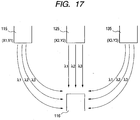
- it is more preferable to execute precise measurements over an extensive scope by implementing various measurements at the same time by combining the spatial separation and wavelength separation mentioned above by setting plural positions of multi-wavelength irradiation mentioned above.
- Fig. 17 shows the case of measuring by transmitting light respectively with three, wavelengths to a light detecting unit 116 from three irradiation positions 115, 125 and 135 set on the same plane (XY plane) in the X axis direction.
- codes CDMA codes
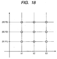
- the concept of separation by codes is as shown in Fig. 18 , and it will be possible to separate nine types of codes by three different wavelengths ( ⁇ 1, ⁇ 2, ⁇ 3) at three different irradiation positions (x1 ⁇ x2 ⁇ x3, y1 ⁇ y2 ⁇ y3).
- Fig. 18 shows the concept of separation by codes by three different wavelengths ( ⁇ 1, ⁇ 2, ⁇ 3) at three different irradiation positions (x1 ⁇ x2 ⁇ x3, y1 ⁇ y2 ⁇ y3).
- the vertical axis shows the separation of irradiation positions, or spatial separation
- the horizontal axis shows the wavelength separation by three wavelengths ( ⁇ 1, ⁇ 2, ⁇ 3).
- the code for each optical signal must be different.
- the value in the z axis direction is considered to be same, and we explained only on the xy plane.
- three-dimensional shape such as human body whose value in the x axis direction is different may be chosen as the object of measurement.
- a light source 1700 with three emitted light output is shown in Fig. 19 .
- This light source outputs emitted light of respectively different wavelengths ⁇ 1, ⁇ 2, ⁇ 3 from light source elements LD1, LD2, and LD3 and irradiate light from almost the same point.
- the method of irradiating light from three light source elements on the same point or as close as possible thereto the method of mixing the emitted light from various light source elements by optical elements such as WDM and the like and irradiating the same point therewith may be used.
- ⁇ 1, ⁇ 2, ⁇ 3 there is no restrictions for the constitution of device, and it is possible to select and/or set (the wavelength value) depending on the object of measurement or the feasibility of producing light-source element.
- the amount of oxygenated and deoxygenated hemoglobin contained in the blood are measured in measuring blood bodies in motion, and in this connection for ⁇ 1, ⁇ 2, ⁇ 3 for example, the values of 850 nm, 750 nm and 680 nm are chosen.
- water body fluid
- LD laser diode
- VCSEL laser diode
- LED element LED element
- RCLED element RCLED element
- the methods of irradiating the irradiation position are unlimited, and for example the method of making the light output terminal of light source element get into contact directly with the irradiation position, and the method of transmitting/irradiating the emitted light of the light source element isolated from the irradiation position to the irradiation position through an optical fiber can be implemented.
- the light source elements LD1, LD2 and LD3 shown in Fig. 19 have respectively common anodes.
- the light source elements are not limited to this construction. It is possible to make the cathode common in response to the driving circuit of the light source element, to contain an mPD (monitor photodiode) for measuring the optical output of the light source element, and it is also possible to measure the living body activities by using light-sensitive elements and at the same time to monitor the optical output of the light source elements and to monitor for their control.
- mPD monitoring photodiode
- the cathode of the mPD may be connected in common, and to make the anode and cathode of the mPD and the anode and cathode of the light source elements LD1, LD2 and LD3 independent.
- there is no limit to the number of built-in mPDs and it is possible to monitor the emitted light from the light source elements LD1, LD2 and LD3 with a single mPD and to monitor emitted light separately by three mPDs, In case of monitoring three emitted light by a single mPD, it will be necessary to demodulate/detect the signal level (light emitting level) by the signal processing similar to the light-sensitive elements described above and thereafter.
- the method of independently measuring and monitoring by using light-sensitive elements by time series at the time of measurement, and subtracting the respective measurement result immediately or after the completion of the measurement as a post-process or the APC (auto power control) method wherein the measurement result of code level by a mPD is considered as the light emitting level by the light source elements and the amplitude of the driving current of the light source elements is controlled so that the measurement result of the code level by this mPD may be constant.
- changes in time series of the transport factor (rate of transmission decrease) between light source elements and light-sensitive elements can be calculated by the subtraction mentioned above, and the APC control enables to measure changes in time series of the level of light received after the demodulation/detection by the light-sensitive elements as the changes in time series of the rate of transmission decrease.
- light-sensitive elements With respect to their system and materials, it is possible to choose and use not only SIPD (silicon photodiode), but also APD (avalanche photodiode), PMT (photomultiplier tube) and other light-sensitive elements depending on the purpose, intensity of received light signals, light emitting wavelength and the like.
- SIPD silicon photodiode
- APD avalanche photodiode
- PMT photomultiplier tube
- other light-sensitive elements depending on the purpose, intensity of received light signals, light emitting wavelength and the like.
- materials it is possible to choose and use known light-sensitive elements constituted by various semiconductors and various chemical compounds including the same.
- FIG. 20 An embodiment of (living body optical measurement) device 2001 made by combining the methods described above is shown in Fig. 20 .
- This device is constituted by the main unit 2002 including a PC and a probe unit 2003.
- the main unit 2002 sets and controls measurements in general, records and stores, and display the results thereof.
- the probe unit 2003 is fixed on the head of the subject 2004, and irradiates light on the head of the subject 2004 and detects data therefrom.
- the modulation of light intensity and the demodulation of the light receiving signal by the CDMA codes of the present invention are performed by the main unit 2002. However, it is possible to make the probe unit 2003 perform these functions by the design of the circuit.
- This device 2001 has the functions of measuring, displaying and recording changes in the brain activity of the subject by measuring blood volume/hemodynamics of oxygenated hemoglobin (OxHb) and deoxygenated hemoglobin (DeOxHb) in the brain.
- the main unit 2002 can set light intensity of the irradiation signal and demodulation code for each irradiation position and controls the beginning and end of the irradiation and measurement of light signals.
- the power source of the main unit 2002 can be reduced smaller in capacity and the precision of measurement can be improved while the dimension of device is reduced.
- the present invention provides a device with small fluctuations in power load by adopting a living body optical measurement device using the conventional CDMA system. This contributes to the miniaturization of device and enables to improve the precision of measurement at the same time.
- the miniaturization of device reduces the restriction on the subject of measurement, and the device can be used in a wide area including specialized institutions such as medical, welfare, research institutions, sport, amusement, education and the like.
Landscapes
- Health & Medical Sciences (AREA)
- Physics & Mathematics (AREA)
- Life Sciences & Earth Sciences (AREA)
- Biomedical Technology (AREA)
- Medical Informatics (AREA)
- Biophysics (AREA)
- Pathology (AREA)
- Engineering & Computer Science (AREA)
- Spectroscopy & Molecular Physics (AREA)
- Heart & Thoracic Surgery (AREA)
- Optics & Photonics (AREA)
- Molecular Biology (AREA)
- Surgery (AREA)
- Animal Behavior & Ethology (AREA)
- General Health & Medical Sciences (AREA)
- Public Health (AREA)
- Veterinary Medicine (AREA)
- Measurement Of The Respiration, Hearing Ability, Form, And Blood Characteristics Of Living Organisms (AREA)
- Measuring Pulse, Heart Rate, Blood Pressure Or Blood Flow (AREA)
Claims (3)
- Optisches Messsystem für lebende Körper, umfassend:mehrere Lichtbestrahlungseinheiten (101, 102, 103), die jeweils eine Codeerzeugungseinheit (711, 721, 731) zum Erzeugen eines speziellen Modulationscodes aus einer Menge von Modulationscodes auf der Grundlage von Hadamard-Codes, eine Modulationseinheit (112, 122, 132) zum Erzeugen eines intensitätsmodulierten Signals, das mittels des von der entsprechenden Codeerzeugungseinheit erzeugten speziellen Modulationscodes moduliert ist, und eine Lichtquelle (113, 123, 133), die mit dem von der Lichtmodulationseinheit bereitgestellten intensitätsmodulierten Signal blinkt, enthalten;eine Lichtdetektionseinheit (116) zum Detektieren von Licht, das einen lebenden Körper durchlaufen hat, der von Lichtquellen bestrahlt wird, die in den mehreren Lichtbestrahlungseinheiten enthalten sind, und zum Ausgeben eines elektrischen Signals undeine Signalverarbeitungseinheit (119) zum Berechnen von Korrelationen zwischen dem Ausgabesignal der Lichtdetektionseinheit und mehrerer Modulationscodes, die jeweils äquivalent zu einem der speziellen Modulationscodes sind, die von den in jeder der Lichtbestrahlungseinheiten enthaltenen Codeerzeugungseinheiten erzeugt worden sind;gekennzeichnet dadurch, dass jeder der mehreren Modulationscodes eine spezielle Bitfolge aufweist, die aus einer ursprünglichen Bitfolge eines entsprechenden Hadamard-Codes um n/2 Bits verschoben ist, wobei n ein Bitzyklus der ursprünglichen Bitfolge des entsprechenden Hadamard-Codes ist.
- Optisches Messsystem für lebende Körper nach Anspruch 1, wobei die Korrelation zwischen den Hadamard-Codes und den Modulationscodes eine negative Logik ist.
- Optisches Messsystem für lebende Körper nach Anspruch 1, wobei jede Lichtbestrahlungseinheit (101, 102, 103) mehrere Lichtquellen (113, 123, 133) zum Emittieren von Licht mit jeweils verschiedenen Wellenlängen umfasst.
Applications Claiming Priority (1)
| Application Number | Priority Date | Filing Date | Title |
|---|---|---|---|
| JP2007182189A JP5049678B2 (ja) | 2007-07-11 | 2007-07-11 | 生体光計測装置 |
Publications (3)
| Publication Number | Publication Date |
|---|---|
| EP2014223A2 EP2014223A2 (de) | 2009-01-14 |
| EP2014223A3 EP2014223A3 (de) | 2012-12-26 |
| EP2014223B1 true EP2014223B1 (de) | 2016-08-31 |
Family
ID=39684155
Family Applications (1)
| Application Number | Title | Priority Date | Filing Date |
|---|---|---|---|
| EP08011379.8A Ceased EP2014223B1 (de) | 2007-07-11 | 2008-06-23 | Optisches Messsystem für lebende Körper |
Country Status (4)
| Country | Link |
|---|---|
| US (1) | US8750951B2 (de) |
| EP (1) | EP2014223B1 (de) |
| JP (1) | JP5049678B2 (de) |
| CN (1) | CN101342079B (de) |
Families Citing this family (9)
| Publication number | Priority date | Publication date | Assignee | Title |
|---|---|---|---|---|
| JPWO2010122703A1 (ja) * | 2009-04-24 | 2012-10-25 | 株式会社日立メディコ | 生体光計測装置 |
| GB201005919D0 (en) * | 2010-04-09 | 2010-05-26 | Univ St Andrews | Optical backscattering diagnostics |
| CN104284629B (zh) * | 2012-05-11 | 2016-04-20 | 株式会社岛津制作所 | 光生物体测量系统及其使用方法 |
| US10548518B2 (en) * | 2014-06-23 | 2020-02-04 | Hitachi, Ltd. | Biophotonic measurement device and method |
| KR101876607B1 (ko) * | 2014-10-30 | 2018-07-16 | 한국과학기술원 | 펌웨어 기반의 휴대 및 확장이 가능한 광분광학 시스템 및 그 제어 방법 |
| KR101876606B1 (ko) * | 2014-10-30 | 2018-07-11 | 한국과학기술원 | 안정적인 데이터 추출을 위한 정합 필터 기반의 광대역 신호 수신기를 이용한 광분광학 시스템 및 그 제어 방법 |
| CN107028589B (zh) * | 2015-12-07 | 2021-02-26 | 本田技研工业株式会社 | 用于生物信号记录的系统和计算机实现的方法 |
| KR102002589B1 (ko) * | 2016-07-21 | 2019-07-22 | 주식회사 올리브헬스케어 | 주파수 도메인 기반의 다파장 생체신호 분석 장치 및 그 방법 |
| KR102024307B1 (ko) * | 2017-11-28 | 2019-09-23 | 성균관대학교산학협력단 | 다중레벨 하다마드 행렬을 이용한 센서 시스템의 송신 및 수신 장치와, 송신 방법 및 수신 방법 |
Family Cites Families (11)
| Publication number | Priority date | Publication date | Assignee | Title |
|---|---|---|---|---|
| JPS57115232A (en) | 1980-07-09 | 1982-07-17 | Deyuuku Univ Inc | Apparatus for measuring metabolic action in internal organ |
| JPS63260532A (ja) | 1987-04-17 | 1988-10-27 | 株式会社島津製作所 | 近赤外線無侵襲生体計測装置 |
| JPS63275323A (ja) | 1987-05-08 | 1988-11-14 | Hamamatsu Photonics Kk | 診断装置 |
| JPH04166144A (ja) | 1990-10-31 | 1992-06-12 | Matsushita Electric Ind Co Ltd | 生体組織測定装置 |
| JPH05317295A (ja) | 1992-05-26 | 1993-12-03 | Omron Corp | 生体組織酸素計測用プローブ |
| JP3365397B2 (ja) * | 2000-05-26 | 2003-01-08 | 株式会社島津製作所 | マルチチャンネル光計測装置 |
| JP3623743B2 (ja) | 2001-02-26 | 2005-02-23 | 株式会社スペクトラテック | 生体情報測定装置 |
| JP2004333344A (ja) | 2003-05-09 | 2004-11-25 | Hitachi Ltd | 光計測方法および装置 |
| US7759622B2 (en) * | 2004-09-10 | 2010-07-20 | Avago Technologies Ecbu Ip (Singapore) Pte. Ltd. | Methods and apparatus for regulating the drive currents of a plurality of light emitters |
| JP4546274B2 (ja) * | 2005-02-09 | 2010-09-15 | 株式会社スペクトラテック | 生体情報計測装置およびその制御方法 |
| JP2006230657A (ja) * | 2005-02-24 | 2006-09-07 | Spectratech Inc | 可視化装置 |
-
2007
- 2007-07-11 JP JP2007182189A patent/JP5049678B2/ja not_active Expired - Fee Related
-
2008
- 2008-06-23 EP EP08011379.8A patent/EP2014223B1/de not_active Ceased
- 2008-06-26 CN CN2008101305228A patent/CN101342079B/zh not_active Expired - Fee Related
- 2008-07-02 US US12/216,360 patent/US8750951B2/en not_active Expired - Fee Related
Also Published As
| Publication number | Publication date |
|---|---|
| EP2014223A3 (de) | 2012-12-26 |
| JP2009017999A (ja) | 2009-01-29 |
| US8750951B2 (en) | 2014-06-10 |
| CN101342079B (zh) | 2010-11-03 |
| US20090015839A1 (en) | 2009-01-15 |
| JP5049678B2 (ja) | 2012-10-17 |
| CN101342079A (zh) | 2009-01-14 |
| EP2014223A2 (de) | 2009-01-14 |
Similar Documents
| Publication | Publication Date | Title |
|---|---|---|
| EP2014223B1 (de) | Optisches Messsystem für lebende Körper | |
| US5891024A (en) | Two stage calibration and analyte measurement scheme for spectrophotomeric analysis | |
| JP5188786B2 (ja) | 生体情報計測装置 | |
| US7729732B2 (en) | Biological information measuring apparatus and method for controlling the apparatus | |
| KR102043319B1 (ko) | 주파수 도메인 기반의 다파장 생체신호 분석 장치 | |
| US9339220B2 (en) | Multi-wavelength physiological monitor | |
| US7230688B1 (en) | System and method for processing information in a pulse oximeter | |
| US20030073890A1 (en) | Plethysmographic signal processing method and system | |
| JP3623743B2 (ja) | 生体情報測定装置 | |
| Ferrell et al. | Medical telesensors | |
| US11419529B2 (en) | Apparatus and method for measuring bio-signal | |
| US12390117B2 (en) | Optical sensor module for speckleplethysmography (SPG) and photoplethysmography (PPG) | |
| US7569821B2 (en) | Biological information measuring apparatus | |
| JP2006230657A (ja) | 可視化装置 | |
| RU2696422C2 (ru) | Система и способ оптического анализа | |
| CN114383640A (zh) | 一种分布式光纤布拉格光栅传感器测控系统 | |
| JPH10216112A (ja) | 無侵襲生化学計測装置 | |
| KR101876607B1 (ko) | 펌웨어 기반의 휴대 및 확장이 가능한 광분광학 시스템 및 그 제어 방법 | |
| JP2004333344A (ja) | 光計測方法および装置 | |
| Yabuki et al. | PPG and SpO 2 recording circuit with ambient light cancellation for trans-nail pulse-wave monitoring system | |
| JPWO2010122703A1 (ja) | 生体光計測装置 | |
| CN113907735A (zh) | 光电容积描记传感器和包括该传感器的半导体设备 | |
| US20250072771A1 (en) | Terminal based on photo plethysmo graph ppg | |
| JP2007111461A (ja) | 生体の光計測装置 | |
| JPH0630915A (ja) | 組織内ヘモグロビン量測定装置 |
Legal Events
| Date | Code | Title | Description |
|---|---|---|---|
| PUAI | Public reference made under article 153(3) epc to a published international application that has entered the european phase |
Free format text: ORIGINAL CODE: 0009012 |
|
| AK | Designated contracting states |
Kind code of ref document: A2 Designated state(s): AT BE BG CH CY CZ DE DK EE ES FI FR GB GR HR HU IE IS IT LI LT LU LV MC MT NL NO PL PT RO SE SI SK TR |
|
| AX | Request for extension of the european patent |
Extension state: AL BA MK RS |
|
| 17P | Request for examination filed |
Effective date: 20100331 |
|
| REG | Reference to a national code |
Ref country code: DE Ref legal event code: R079 Ref document number: 602008045951 Country of ref document: DE Free format text: PREVIOUS MAIN CLASS: A61B0005000000 Ipc: A61B0005145500 |
|
| PUAL | Search report despatched |
Free format text: ORIGINAL CODE: 0009013 |
|
| AK | Designated contracting states |
Kind code of ref document: A3 Designated state(s): AT BE BG CH CY CZ DE DK EE ES FI FR GB GR HR HU IE IS IT LI LT LU LV MC MT NL NO PL PT RO SE SI SK TR |
|
| AX | Request for extension of the european patent |
Extension state: AL BA MK RS |
|
| RIC1 | Information provided on ipc code assigned before grant |
Ipc: A61B 5/00 20060101ALI20121116BHEP Ipc: G01N 21/00 20060101ALI20121116BHEP Ipc: A61B 5/1455 20060101AFI20121116BHEP |
|
| AKX | Designation fees paid |
Designated state(s): DE GB IT |
|
| GRAP | Despatch of communication of intention to grant a patent |
Free format text: ORIGINAL CODE: EPIDOSNIGR1 |
|
| INTG | Intention to grant announced |
Effective date: 20160314 |
|
| GRAS | Grant fee paid |
Free format text: ORIGINAL CODE: EPIDOSNIGR3 |
|
| GRAA | (expected) grant |
Free format text: ORIGINAL CODE: 0009210 |
|
| AK | Designated contracting states |
Kind code of ref document: B1 Designated state(s): DE GB IT |
|
| REG | Reference to a national code |
Ref country code: GB Ref legal event code: FG4D |
|
| REG | Reference to a national code |
Ref country code: DE Ref legal event code: R096 Ref document number: 602008045951 Country of ref document: DE |
|
| REG | Reference to a national code |
Ref country code: DE Ref legal event code: R097 Ref document number: 602008045951 Country of ref document: DE |
|
| PLBE | No opposition filed within time limit |
Free format text: ORIGINAL CODE: 0009261 |
|
| STAA | Information on the status of an ep patent application or granted ep patent |
Free format text: STATUS: NO OPPOSITION FILED WITHIN TIME LIMIT |
|
| 26N | No opposition filed |
Effective date: 20170601 |
|
| PGFP | Annual fee paid to national office [announced via postgrant information from national office to epo] |
Ref country code: IT Payment date: 20170620 Year of fee payment: 10 |
|
| PGFP | Annual fee paid to national office [announced via postgrant information from national office to epo] |
Ref country code: DE Payment date: 20180612 Year of fee payment: 11 |
|
| PGFP | Annual fee paid to national office [announced via postgrant information from national office to epo] |
Ref country code: GB Payment date: 20180620 Year of fee payment: 11 |
|
| PG25 | Lapsed in a contracting state [announced via postgrant information from national office to epo] |
Ref country code: IT Free format text: LAPSE BECAUSE OF NON-PAYMENT OF DUE FEES Effective date: 20180623 |
|
| REG | Reference to a national code |
Ref country code: DE Ref legal event code: R119 Ref document number: 602008045951 Country of ref document: DE |
|
| GBPC | Gb: european patent ceased through non-payment of renewal fee |
Effective date: 20190623 |
|
| PG25 | Lapsed in a contracting state [announced via postgrant information from national office to epo] |
Ref country code: GB Free format text: LAPSE BECAUSE OF NON-PAYMENT OF DUE FEES Effective date: 20190623 Ref country code: DE Free format text: LAPSE BECAUSE OF NON-PAYMENT OF DUE FEES Effective date: 20200101 |