EP2012934B1 - Mehrfunktions-handbrause - Google Patents
Mehrfunktions-handbrause Download PDFInfo
- Publication number
- EP2012934B1 EP2012934B1 EP07724668A EP07724668A EP2012934B1 EP 2012934 B1 EP2012934 B1 EP 2012934B1 EP 07724668 A EP07724668 A EP 07724668A EP 07724668 A EP07724668 A EP 07724668A EP 2012934 B1 EP2012934 B1 EP 2012934B1
- Authority
- EP
- European Patent Office
- Prior art keywords
- hand
- water
- held
- region
- piece
- Prior art date
- Legal status (The legal status is an assumption and is not a legal conclusion. Google has not performed a legal analysis and makes no representation as to the accuracy of the status listed.)
- Not-in-force
Links
- XLYOFNOQVPJJNP-UHFFFAOYSA-N water Substances O XLYOFNOQVPJJNP-UHFFFAOYSA-N 0.000 claims abstract description 53
- 230000000295 complement effect Effects 0.000 claims description 4
- 230000002093 peripheral effect Effects 0.000 claims description 3
- 239000007921 spray Substances 0.000 description 5
- 238000004140 cleaning Methods 0.000 description 4
- 238000012423 maintenance Methods 0.000 description 4
- 210000002445 nipple Anatomy 0.000 description 4
- 230000001427 coherent effect Effects 0.000 description 2
- 210000003813 thumb Anatomy 0.000 description 2
- 210000003811 finger Anatomy 0.000 description 1
- 239000003595 mist Substances 0.000 description 1
- 230000000149 penetrating effect Effects 0.000 description 1
- 239000007787 solid Substances 0.000 description 1
- 230000007704 transition Effects 0.000 description 1
Images




Classifications
-
- B—PERFORMING OPERATIONS; TRANSPORTING
- B05—SPRAYING OR ATOMISING IN GENERAL; APPLYING FLUENT MATERIALS TO SURFACES, IN GENERAL
- B05B—SPRAYING APPARATUS; ATOMISING APPARATUS; NOZZLES
- B05B1/00—Nozzles, spray heads or other outlets, with or without auxiliary devices such as valves, heating means
- B05B1/14—Nozzles, spray heads or other outlets, with or without auxiliary devices such as valves, heating means with multiple outlet openings; with strainers in or outside the outlet opening
- B05B1/16—Nozzles, spray heads or other outlets, with or without auxiliary devices such as valves, heating means with multiple outlet openings; with strainers in or outside the outlet opening having selectively- effective outlets
- B05B1/1627—Nozzles, spray heads or other outlets, with or without auxiliary devices such as valves, heating means with multiple outlet openings; with strainers in or outside the outlet opening having selectively- effective outlets with a selecting mechanism comprising a gate valve, a sliding valve or a cock
- B05B1/1636—Nozzles, spray heads or other outlets, with or without auxiliary devices such as valves, heating means with multiple outlet openings; with strainers in or outside the outlet opening having selectively- effective outlets with a selecting mechanism comprising a gate valve, a sliding valve or a cock by relative rotative movement of the valve elements
-
- B—PERFORMING OPERATIONS; TRANSPORTING
- B05—SPRAYING OR ATOMISING IN GENERAL; APPLYING FLUENT MATERIALS TO SURFACES, IN GENERAL
- B05B—SPRAYING APPARATUS; ATOMISING APPARATUS; NOZZLES
- B05B1/00—Nozzles, spray heads or other outlets, with or without auxiliary devices such as valves, heating means
- B05B1/02—Nozzles, spray heads or other outlets, with or without auxiliary devices such as valves, heating means designed to produce a jet, spray, or other discharge of particular shape or nature, e.g. in single drops, or having an outlet of particular shape
- B05B1/04—Nozzles, spray heads or other outlets, with or without auxiliary devices such as valves, heating means designed to produce a jet, spray, or other discharge of particular shape or nature, e.g. in single drops, or having an outlet of particular shape in flat form, e.g. fan-like, sheet-like
-
- B—PERFORMING OPERATIONS; TRANSPORTING
- B05—SPRAYING OR ATOMISING IN GENERAL; APPLYING FLUENT MATERIALS TO SURFACES, IN GENERAL
- B05B—SPRAYING APPARATUS; ATOMISING APPARATUS; NOZZLES
- B05B1/00—Nozzles, spray heads or other outlets, with or without auxiliary devices such as valves, heating means
- B05B1/14—Nozzles, spray heads or other outlets, with or without auxiliary devices such as valves, heating means with multiple outlet openings; with strainers in or outside the outlet opening
- B05B1/18—Roses; Shower heads
Definitions
- the invention relates to a multi-function hand shower according to the preamble of patent claim 1.
- effervescent jets which can be produced by means of such conventional multi-function hand-held jets include, for example, standard effervescent jets, but also massage effervescent jets which emit elevated pressure compared to standard effervescent jets, and, for example, effervescent jars which emit the multifunctional effervescent jets. Leave hand shower as a flood of water in the form of a largely coherent water curtain. It is also possible to produce spray mist, rain-like droplet sequences or combinations of different types of effervescent spray with such multi-function handheld showerheads.
- a multi-function hand shower in which the manually operable changeover means comprise a Umstellorgan and are arranged in the hand area, for example, from DE 100 17 044 A1 known.
- the switching means are provided there in the form of a relatively complicated multi-way valve.
- the Umstellorgan for this includes a plurality of closing elements, which can each close a water-bearing channel. Each of the closing elements has a 0-ring and is in turn with a tilting element connected, which is mounted on a pin and can be actuated by means of push buttons.
- the actuation of the changeover means may alternatively be effected in a manner known per se also by a housing part of the head region, which is rotatable relative to another housing part in the head region.
- the internal structure of the changeover means as a whole is rather complicated.
- a multi-function hand shower of the type mentioned is from the DE 102 32 463 A1 known. It has in the transition region between a handle and the shower head on a valve which allow by means of two collars in the outer shell of the handle on the one hand to specify the flow and on the other hand, the water-emitting nozzles. Even there, the mechanical structure is quite complex and maintenance and / or cleaning difficult.
- the object of the invention is to provide a multi-function hand shower of the type mentioned, in which the switching means are mechanically simpler and easier to handle for the user.
- the Umstellorgan serves as a kind of switch for the flow of water inside the hand shower.
- the Umstellorgan is designed as a rotary wheel, the peripheral surface at least partially serves as an actuating surface and at least partially projects through an opening in the hand area to the outside. So the Umstellorgan is easily accessible to the user.
- the opening lies in a region of the hand area located on the side of the water outlet openings, which is particularly convenient for the user.
- the elliptical outer cross section in the handle portion of the hand area is also convenient to handle by the user.
- the switching means comprise a pivot on which the Umstellorgan is rotatably mounted in the interior of the hand area. In this way, a rotary switch can be realized, which is often perceived as a more pleasant operation than, for example, the operation of a slider.
- the pivot extends substantially perpendicular to a lying in the region of the pivot cross-sectional area of the hand area.
- the pivot pin thus lies parallel to the longitudinal axis of the hand region, and the changeover element is rotated transversely to this longitudinal axis.
- the changeover means comprise a distributor element which works together with the changeover element and which has a through bore with a distributor opening facing the changeover element, via which water can be supplied to the water-conducting throughbore of the changeover element in all functional positions of the changeover element.
- the distributor opening of the distributor element is semicircular and the water-conducting through hole of the Umstellorgans by a rotational movement of the Umstellorgans along the semicircular distributor opening is movable. In this way, it is ensured in a simple manner that the water-conducting through hole of the Umstellorgans is always supplied with the hand shower water supplied.
- the maintenance and / or cleaning of the hand shower is facilitated in a simple manner, when the hand area as a separate handpiece and the head portion are formed as a separate head piece, which are detachably connected to each other.
- the hand shower is then in two parts and it is possible to disassemble the hand shower for maintenance and / or cleaning purposes.
- different head pieces can be combined with one and the same handpiece.
- the head pieces can be different both in design and in their function.
- different head pieces for example, each have different water-carrying channels, which lead to different water outlet openings, so that different shower spray variants can be produced with different head pieces.
- the user can then decide which combination of selectable effervescent jets he prefers and use a corresponding headpiece together with the same handpiece.
- the head piece has external connecting pieces, each of which is connected to one of the water-carrying channels of the head piece, and if the handpiece has complementary receptacles to the connecting piece of the head piece.
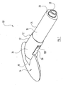
- FIG. 1 a multi-function hand-held shower, generally designated by the reference numeral 10, is shown, which comprises a hand region 12 and a head region 14.
- the hand area 12 are formed as a separate handpiece 16 and the head portion 14 as a separate head piece 18. This will be discussed further below.
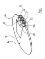
- the head piece 18 includes a shower base 20 (see. FIG. 2 ), which has a plurality of water outlet openings 22, 24, 26.
- a shower base 20 see. FIG. 2
- the three massage jet openings 22 are radially outwardly partially surrounded by a circular arc water outlet slot 24. Through this, the water emerges as a largely coherent water curtain, whereby the function of a surge shower is realized.
- radially outermost in the shower base 20 relatively many water outlet openings 26 are provided, through which water emerges as a soft jet in the form of a rain-like droplet sequence. Of the soft-jet water outlet openings 26 only one is provided with a reference numeral in the figures.
- a connecting nipple 28 is provided, on which an external thread 30 is located.
- the multi-function hand shower 10 can be connected in a manner known per se with a not further interest shower hose.
- the handpiece 16 of the multi-function hand shower 10 comprises a control portion 32 adjacent to the head portion 14 and an adjoining handle portion 34 which carries the nipple 28.
- the handle portion 34 is as a substantially solid part with elliptical External cross-section formed and has such an outer periphery that the multi-function hand shower 10 in the handle portion 34 can be conveniently held in the usual manner by a user with one hand.
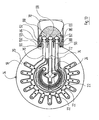
- a manifold 36 is held with a circular cross-section (see. FIG. 6 ).
- the through hole of the connecting nipple 28 goes in the direction of this distributor piece 36 in one to the longitudinal axis 37 of the handle portion 34, the section line VI-VI in FIG. 5 corresponds, coaxial circular cylindrical water inlet chamber 38 via.
- This is connected via an obliquely to the longitudinal axis 37 out water-bearing passageway 40 in the handle portion 34 with a distributor approach 36 eccentrically penetrating water-bearing through hole 42 in combination (see. FIG. 7 ).
- the through hole 42 of the manifold 36 has on its side adjacent to the passage 40 side a passage 40 substantially corresponding circular cross-section.
- On the opposite side of the passageway 40 of the manifold 36 extends its water-bearing through hole 42, however, to a semicircular opening 44 which extends from the portion of the through hole 42 having a circular cross-section symmetrically in the clockwise and counterclockwise directions, in particular in FIG. 7 can be seen.
- a pivot pin 46 is provided, whose longitudinal axis is coaxial with the longitudinal axis of the manifold 36 and which is rigidly connected thereto. As in particular in FIG. 5 can be seen, penetrates the pivot pin 46, the manifold 36 in the direction of the handle portion 34 and protrudes with an end portion in the latter. Compared with the longitudinal axis 37 of the handle portion 34 of the handpiece 16 extend the longitudinal axis of the pivot pin 46 and the longitudinal axis of the manifold 36 in FIG. 5 a bit down.
- the pivot pin 46 thus lies axially parallel to the longitudinal axis 37 of the handle portion 34 of the handpiece 16. In other words, the pivot pin 46 is perpendicular to a cross-sectional area of the handpiece 16, which lies in the region of the pivot 46.
- a Umstellorgan in the form of a rotary wheel 50 is rotatably held.
- the rotary wheel 50 has a cross-section of the pivot 46 complementary through hole 52, with which it is pushed onto the end portion 48 of the guide pin 46 (see also FIG. 8 ).
- Radially spaced from the through hole 52 of the rotary wheel 50 this has a water-bearing through hole 54. This is radially spaced so far from the through hole 52 that it comes to rest over the semicircular opening 44 of the distributor extension 36 when the rotary wheel 50 is pushed onto the pivot pin 46.
- the diameter of the water-carrying through-hole 54 of the rotary wheel 50 substantially corresponds to the radial width of the semicircular-shaped opening 44 of the distributor piece 36. This is particularly in FIG. 8 clearly visible.
- Both the distributor piece 36 and the rotary wheel 50 are seated in a recess 56 in the end face of the control section 32 of the handpiece 16 adjacent to the handle section 32.
- the recess 56 has an elliptical cross section and has a depth which corresponds to the common longitudinal extent of the distributor piece 36 and of the Turning wheel 50 corresponds.
- the bottom 58 of the recess 56 in the control section 32 of the handpiece 16 thus abuts against the adjacent end face of the rotary wheel 50.
- connection channels 60, 62, 64 extend axially parallel to the longitudinal axis 37 of the handle section 34 of the handpiece 16 respectively to further channels 66, 68 and 70.
- the connection channels 60, 62 and 64 are at the same radial distance arranged to the longitudinal axis of the guide pin 46, as is made FIG. 9 is apparent.
- the connecting channels 60, 62 and 64 are equidistant from each other over the semicircular opening 44 of the manifold 36, but are separated therefrom by the rotary wheel 50.
- the cross-section of the connecting channels 60, 62 and 64 substantially corresponds to the cross section of the water-carrying through-hole 54 in the rotary wheel 50.
- the continuing channels 66, 68 and 70 in the control section 32 of the handpiece 16 extend obliquely to the longitudinal axis 37 of the handle portion 34 and are each provided with one of in FIG. 10 to be recognized water-conducting supply channels 72, 74 and 76 in the head piece 18 in conjunction.
- the channel 72 leads to the outlet slot 24
- the channel 74 leads to the massage water outlet openings 22
- the channel 76 leads to the soft-jet water outlet openings 26th
- the multi-function hand shower 10 thus downstream of the rotary wheel 50, a first water-bearing waterway 60, 66, 72, a second water-bearing waterway 62, 68, 74 and a third water-bearing waterway 64, 70, 76, which in the interior of the control section 32nd of the handpiece 16 and inside the head piece 18 of the multi-function hand shower 10.
- the handpiece 16 and the head piece 18 are, as mentioned above, formed as separate components and releasably connected to each other.
- the head piece 18 facing the end portion 78 of the control portion 32 of the handpiece 16 is fork-shaped in such a way that it engages over the head piece 18 from the outside of the shower base 20 and on this opposite outer surface fit, which is particularly in the FIGS. 1 and 2 easy to recognize.
- the end portion 78 of the control portion 32 of the handpiece 16 is inclined relative to the remaining part of the control portion 32 by an angle of about 30 °, whereby the user the handling of the multi-function hand shower 10 is facilitated.
- the water-carrying supply channels 72, 74 and 76 in the head piece 18 each open into a connecting piece 80, 82 and 84 projecting above the head piece 18.
- These connecting pieces 80, 82, 84 are seated in corresponding receiving bores 86 when the head piece 18 is pushed into the control section 32 of the handpiece 16 , 88 and 90 in the control section 32 of the handpiece 16, which in turn lead to the continuing channels 66, 68 and 70 in the handpiece 16.
- the connecting pieces 80, 82 and 84 of the head piece 18 are sealed relative to the inner walls of the receiving bores 86, 88 and 90 in the handpiece 16 via O-rings, of which in the Figures 5 . 6 and 10 only one is provided with the reference numeral 92.
- a locking device 94 is provided, which in particular in FIG. 6 easy to recognize.
- This includes two rockers 96, which sit in each opposite recesses 98 in the control section 32 of the handpiece 16 and therein by one in each case FIG. 6 perpendicular to the plane standing pivot 100 are pivotable.
- the rockers 96 At their ends facing the head piece 18, the rockers 96 have a latching nose 102 projecting inwards in the direction of the longitudinal axis 37 of the handpiece 16, which engage in notches 104 which are provided correspondingly in the outer circumferential surface of the outer connecting pieces 80 and 84.
- the notches 104 are also in FIG. 4 clearly visible.
- the locking lugs 102 of the rockers 96 can engage with inserted head piece 18 each in a notch 104, the walls of the outer receiving holes 86 and 90 at the level of the locking lugs 102 are each provided with a corresponding passage 105, which is particularly in FIG. 10 easy to recognize.
- the rockers 96 are pressed by means of coil springs 106 in the direction of their detent position in which they engage in the notches 104.
- the coil springs 106 are each clamped at the opposite end of the latching lug 102 each rocker 96 between this and the parallel to the respective rocker 96 extending bottom of the recess 98 under tension.
- the coil springs 106 are each prevented by a short retaining pin 107 on the respective rocker 96 at a lateral breakout.
- the rockers 96 have on their outside accessible to the user in the FIGS. 1 . 2 and 3 to be seen finger recesses 108 which are opposite to the coil spring 106 respectively.
- the respective rocker 96 pivots against the force of the spiral spring 106 about the corresponding pivot pin 100 and the latching nose 102 is moved out of the notch 104.
- the locking of the head piece 18 is released in the handpiece 16 and it can be removed by the user from the handpiece 16.
- the rotary wheel 50 protrudes through a slot 110 in the control section 32 of the handpiece 16 out of the same to the outside.
- the outer circumferential surface of the rotary wheel 50 is executed wavy in regions, in particular along that peripheral region, which can protrude through the slot 110 outwardly at the various possible positions of the rotary wheel 50 therethrough. In this way, an actuating surface 112 of the rotary wheel 50 is formed.
- the rotation of the rotary wheel 50 takes place, for example, in that the user with the thumb of that hand, which surrounds the multi-function hand shower 10 in the handle portion 34 of the handpiece 16, presses on the actuating surface 112 of the rotary wheel 50 and this rotated by a corresponding thumb movement.
- the head piece 18 is formed such that three different spray jets, namely massage jets, a water curtain and soft jets, can be generated.
- the head piece 18 is formed as a separate component, the handpiece 16, however, with functionally different, user-selectable head pieces 18 work together.
- These mutually different headers 18 must of course be designed so that they always have to the receiving holes 86, 88 and 90 of the handpiece 16 complementary connecting pieces 80, 82 and 84 and also coincide in their outer contour. The latter applies at least to that region of each headpiece 18 which is encompassed by the end region 78 of the control section 32 in the manner explained above.
- the water-carrying supply ducts 72, 74 and 76 in the interior of the head pieces 18, however, can be designed differently and / or lead to different water outlet openings, which in turn different spray jets can be generated.
Landscapes
- Bathtubs, Showers, And Their Attachments (AREA)
- Nozzles (AREA)
- Massaging Devices (AREA)
Description
- Die Erfindung betrifft eine Mehrfunktions-Handbrause nach dem Oberbegriff des Patentanspruchs 1.
- Zu den unterschiedlichen Arten von Brausestrahlen, welche mittels derartiger herkömmlicher Mehrfunktions-Handbrausen erzeugt werden können, zählen beispielsweise übliche Standard-Brausestrahlen, aber auch Massage-Brausestrahlen, welche mit einem gegenüber Standard-Brausestrahlen erhöhtem Druck austreten, sowie beispielsweise Brausestrahlen, die die Mehrfunktions-Handbrause als Wasserschwall in Form eines weitgehend zusammenhängenden Wasservorhangs verlassen. Auch Sprühnebel, regenartige Tropfenfolgen oder Kombinationen verschiedener Arten von Brausestrahlen können mit derartigen Mehrfunktions-Handbrausen erzeugt werden.
- Aufgrund der Möglichkeit für den Benutzer, abhängig von seinem Befinden und seinen Bedürfnissen die Art der Brausestrahlen einstellen zu können, erfreuen sich Mehrfunktions-Handbrausen großer Beliebtheit. Eine Mehrfunktions-Handbrause, bei der die von Hand betätigbaren Umstellmittel ein Umstellorgan umfassen und im Handbereich angeordnet sind, ist beispielsweise aus der
DE 100 17 044 A1 bekannt. Die Umstellmittel sind dort in Form eines relativ kompliziert aufgebauten Mehrwegeventils vorgesehen. Das Umstellorgan dafür umfasst mehrere Verschließelemente, welche jeweils einen wasserführenden Kanal verschließen können. Jedes der Verschließelemente weist einen 0-Ring auf und ist wiederum mit einem Kippelement verbunden, das über einen Zapfen gelagert ist und mittels Drucktasten betätigt werden kann. - Die Betätigung der Umstellmittel kann in einer an und für sich bekannten Weise alternativ auch durch ein Gehäuseteil des Kopfbereichs erfolgen, der gegenüber einem anderen Gehäuseteil im Kopfbereich verdrehbar ist. Durch Betätigen der Umstellmittel wird dabei die Betriebsart geändert, indem das Wasser im Inneren des Kopfbereiches entsprechend umgelenkt und beispielsweise zu einer anderen Art von Wasseraustrittsöffnungen geleitet wird. Auch bei dieser Variante ist der innere Aufbau der Umstellmittel insgesamt jedoch recht aufwändig.
- Bekannte Umstellmittel bestehen häufig, wie z.B. in der
DE 100 17 044 A1 beschrieben, aus einer Vielzahl von Einzelteilen und sind dementsprechend mechanisch recht anfällig. Auch ist eine Wartung und/oder Reinigung durch den komplizierten Aufbau erschwert. - Eine Mehrfunktions-Handbrause der eingangs genannten Art ist aus der
DE 102 32 463 A1 bekannt geworden. Es weist im Übergangsbereich zwischen einem Handgriff und dem Brausekopf ein Ventil auf, welche mittels zweier Stellringe im Außenmantel des Handgriffs einerseits den Durchfluss und andererseits die wasserabgebenden Düsen vorzugeben gestatten. Auch dort ist der mechanische Aufbau recht komplex und die Wartung und/oder Reinigung schwierig. - Aufgabe der Erfindung ist es, eine Mehrfunktions-Handbrause der eingangs genannten Art zu schaffen, bei welcher die Umstellmittel mechanisch einfacher aufgebaut und für den Benutzer bequem zu handhaben sind.
- Diese Aufgabe wird durch eine Mehrfunktions-Handbrause gemäß dem Anspruch 1 gelöst.
- Wie im Stand der Technik an sich bekannt, dient das Umstellorgan gewissermaßen als Weiche für den Wasserstrom im Inneren der Handbrause. Das Umstellorgan ist als Drehrad ausgebildet, dessen Umfangsfläche wenigstens bereichsweise als Betätigungsfläche dient und wenigstens bereichsweise durch eine Öffnung im Handbereich nach außen ragt. So ist das Umstellorgan für den Benutzer gut zugänglich.
- Erfindungsgemäß liegt die Öffnung in einem auf der Seite der Wasseraustrittsöffnungen liegenden Bereich des Handbereichs, was besonders bequem für den Benutzer ist. Auch der elliptische Außenquerschnitt im Griffabschnitt des Handbereichs dient der bequemen Handhabung durch den Benutzer.
- Dabei ist es vorteilhaft, wenn die Umstellmittel einen Drehzapfen umfassen, auf welchem das Umstellorgan im Inneren des Handbereichs drehbar gelagert ist. Auf diese Weise kann ein Drehschalter realisiert werden, was häufig als angenehmere Bedienungsmöglichkeit empfunden wird als beispielsweise die Betätigung eines Schiebers.
- Eine gutes Handling wird erzielt, wenn der Drehzapfen im wesentlichen senkrecht zu einer im Bereich des Drehzapfens liegenden Querschnittsfläche des Handbereichs verläuft. Bei einem geradlinigen Handbereich liegt der Drehzapfen damit also parallel zur Längsachse des Handbereichs und das Umstellorgan wird quer zu dieser Längsachse verdreht.
- Eine technisch vorteilhafte Lösung wird erzielt, wenn die Umstellmittel ein mit dem Umstellorgan zusammen arbeitendes Verteilerelement umfassen, welches eine Durchgangsbohrung mit einer dem Umstellorgan zugewandten Verteileröffnung aufweist, über welche der wasserführenden Durchgangsbohrung des Umstellorgans in allen Funktionsstellungen des Umstellorgans Wasser zuführbar ist. Dabei ist es bevorzugt, wenn die Verteileröffnung des Verteilerelements halbkreisringförmig ist und die wasserführende Durchgangsbohrung des Umstellorgans durch eine Drehbewegung des Umstellorgans entlang der halbkreisringförmigen Verteileröffnung verfahrbar ist. Auf diese Weise ist auf einfache Art sichergestellt, dass die wasserführende Durchgangsbohrung des Umstellorgans stets mit der Handbrause zugeführtem Wasser beaufschlagt ist.
- Die Wartung und/oder Reinigung der Handbrause wird auf einfache Weise erleichtert, wenn der Handbereich als separates Handstück und der Kopfbereich als separates Kopfstück ausgebildet sind, die lösbar miteinander verbunden sind. Die Handbrause ist dann also zweiteilig und es besteht so die Möglichkeit, die Handbrause zu Wartungs und/oder Reinigungszwecken auseinanderzunehmen. Auf diese Weise können darüber hinaus unterschiedliche Kopfstücke mit ein und demselben Handstück kombiniert werden. Die Kopfstücke können dabei sowohl im Design als auch in ihrer Funktion unterschiedlich sein. Was unterschiedliche Funktionen betrifft , können unterschiedliche Kopfstücke beispielsweise jeweils verschiedene wasserführende Kanäle aufweisen, die zu unterschiedlichen Wasseraustrittsöffnungen führen, so dass mit unterschiedlichen Kopfstücken verschiedene Brausestrahl-Varianten erzeugt werden können.
- Der Benutzer kann dann entscheiden, welche Kombination von wählbaren Brausestrahlen er bevorzugt und ein entsprechendes Kopfstück zusammen mit demselben Handstück verwenden.
- Dabei ist es insbesondere günstig, wenn das Kopfstück außenliegende Verbindungsstutzen aufweist, von denen jeder mit einem der wasserführenden Kanäle des Kopfstücks verbunden ist, und wenn das Handstück zu den Verbindungsstutzen des Kopfstücks komplementäre Aufnahmen aufweist.
- Nachstehend wird ein Ausführungsbeispiel der Erfindung anhand der Zeichnung näher erläutert; es zeigen:
- Figur 1
- eine perspektivische Ansicht einer Mehrfunk- tions-Handbrause aus einer ersten Blick- richtung;
- Figur 2
- eine perspektivische Ansicht der Mehrfunk- tions-Handbrause nach
Figur 1 aus einer zweiten Blickrichtung; - Figur 3
- eine der
Figur 2 entsprechender Ansicht des als separates Handstück ausgebildeten Hand- bereichs der Mehrfunktions-Handbrause; - Figur 4
- eine der
Figur 1 entsprechende Ansicht des als separates Kopfstück ausgebildeten Kopf- bereichs der Mehrfunktions-Handbrause; - Figur 5
- einen Schnitt durch die Mehrfunktions-Hand- brause entlang der Schnittlinie V-V in Fi- gur 6;
- Figur 6
- einen Schnitt durch die Mehrfunktions-Handbrause entlang der Schnittlinie VI-VI in
Figur 5 ; - Figur 7
- einen Schnitt durch die Mehrfunktions-Hand- brause entlang der Schnittlinie VII-VII in
Figur 5 ; - Figur 8
- einen Schnitt durch die Mehrfunktions-Hand- brause entlang der Schnittlinie VIII-VIII in
Figur 5 ; - Figur 9
- einen Schnitt durch die Mehrfunktions-Hand- brause entlang der Schnittlinie IX-IX in
Figur 5 ; und - Figur 10
- einen Schnitt durch die Mehrfunktions-Hand- brause entlang der Schnittlinie X-X in
Figur 5 . - In
Figur 1 ist eine insgesamt mit dem Bezugszeichen 10 gekennzeichnete Mehrfunktions-Handbrause gezeigt, welche einen Handbereich 12 und einen Kopfbereich 14 umfaßt. Wie insbesondere anhand derFiguren 3 und4 zu erkennen ist, sind der Handbereich 12 als separates Handstück 16 und der Kopfbereich 14 als separates Kopfstück 18 ausgebildet. Darauf wird weiter unten nochmals näher eingegangen. - Das Kopfstück 18 umfaßt einen Brauseboden 20 (vgl.
Figur 2 ), welcher eine Vielzahl von Wasseraustrittsöffnungen 22, 24, 26 aufweist. Es sind drei radial innenliegende Wasseraustrittsöffnungen 22 vorgesehen, durch welche Brausestrahlen mit einem relativ hohen Wasserdruck austreten, wodurch die Funktion von Massagestrahlen verwirklicht ist. Die drei Massagestrahl-Öffnungen 22 sind radial außen bereichsweise von einem kreisbogenförmigen Wasseraustrittsschlitz 24 umgeben. Durch diesen tritt das Wasser als weitgehend zusammenhängender Wasservorhang aus, wodurch die Funktion einer Schwallbrause verwirklicht ist. Schließlich sind radial außenliegend im Brauseboden 20 relativ viele Wasseraustrittsöffnungen 26 vorgesehen, durch welche Wasser als Weichstrahl in Form einer regenartigen Tröpfchenfolge austritt. Von den Weichstrahl-Wasseraustrittsöffnungen 26 ist in den Figuren nur jeweils eine mit einem Bezugszeichen versehen. - An dem dem Kopfbereich 14 gegenüberliegenden Ende des Handstücks 16 ist ein Anschlußnippel 28 vorgesehen, auf dem sich ein Außengewinde 30 befindet. Über Letzteres kann die Mehrfunktions-Handbrause 10 in an und für sich bekannter Weise mit einem hier nicht weiter interessierenden Brauseschlauch verbunden werden.
- Das Handstück 16 der Mehrfunktions-Handbrause 10 umfaßt einen zu dem Kopfbereich 14 benachbarten Steuerabschnitt 32 sowie einen daran angrenzenden Griffabschnitt 34, welcher den Anschlußnippel 28 trägt. Der Griffabschnitt 34 ist als im wesentlichen massives Teil mit elliptischem Außen-Querschnitt ausgebildet und weist einen derartigen Außenumfang auf, daß die Mehrfunktions-Handbrause 10 im Griffabschnitt 34 in üblicher Weise bequem von einem Benutzer mit einer Hand gehalten werden kann.
- An der dem Anschlußnippel 28 gegenüberliegenden Stirnseite des Griffabschnitts 34 ist ein Verteilerstück 36 mit kreisrundem Querschnitt gehalten (vgl.
Figur 6 ). Die Durchgangsbohrung des Anschlußnippels 28 geht in Richtung auf dieses Verteilerstück 36 in eine zur Längsachse 37 des Griffabschnitts 34, die der Schnittlinie VI-VI inFigur 5 entspricht, koaxiale kreiszylindrische Wassereintrittskammer 38 über. Diese steht über einen schräg zur Längsachse 37 geführten wasserführenden Durchgangskanal 40 im Griffabschnitt 34 mit einer den Verteileransatz 36 exzentrisch durchdringenden wasserführenden Durchgangsbohrung 42 in Verbindung (vgl.Figur 7 ). Die Durchgangsbohrung 42 des Verteilerstücks 36 hat auf ihrer an den Durchgangskanal 40 angrenzenden Seite einen dem Durchgangskanal 40 im wesentlichen entsprechenden kreisrunden Querschnitt. Auf der dem Durchgangskanal 40 gegenüberliegenden Seite des Verteilerstücks 36 erweitert sich dessen wasserführende Durchgangsbohrung 42 dagegen zu einer halbkreisringförmigen Öffnung 44, welche sich ausgehend von dem Abschnitt der Durchgangsbohrung 42 mit kreisrundem Querschnitt symmetrisch in die Richtungen mit dem und gegen den Uhrzeigersinn erstreckt, wie es insbesondere inFigur 7 zu erkennen ist. - Über die freie Stirnseite des Verteilerstücks 36 hinausragend ist ein Drehzapfen 46 vorgesehen, dessen Längsachse koaxial zur Längsachse des Verteilerstücks 36 verläuft und welcher starr mit diesem verbunden ist. Wie insbesondere in
Figur 5 zu erkennen ist, durchdringt der Drehzapfen 46 das Verteilerstück 36 in Richtung auf den Griffabschnitt 34 und ragt mit einem Endbereich in letzteren hinein. Gegenüber der Längsachse 37 des Griffabschnitts 34 des Handstücks 16 verlaufen die Längsachse des Drehzapfens 46 und die Längsachse des Verteilerstücks 36 inFigur 5 ein wenig nach unten versetzt. Der Drehzapfen 46 liegt folglich achsparallel zur Längsachse 37 des Griffabschnitts 34 des Handstücks 16. Anders ausgedrückt verläuft der Drehzapfen 46 senkrecht zu einer Querschnittsfläche des Handstücks 16, die im Bereich des Drehzapfens 46 liegt. - Auf dem über das Verteilerstück 36 in Richtung auf das Kopfstück 18 ragenden Endbereich 48 des Drehzapfens 46 wird ein Umstellorgan in Form eines Drehrads 50 verdrehbar gehalten. Dazu weist das Drehrad 50 eine zum Querschnitt des Drehzapfens 46 komplementäre Durchgangsbohrung 52 auf, mit der es auf den Endbereich 48 des Führungszapfens 46 aufgeschoben ist (vgl. auch
Figur 8 ). Radial von der Durchgangsbohrung 52 des Drehrads 50 beabstandet weist dieses eine wasserführende Durchgangsbohrung 54 auf. Diese ist radial so weit von der Durchgangsbohrung 52 beabstandet, daß sie über der halbkreisringförmigen Öffnung 44 des Verteileransatzes 36 zu liegen kommt, wenn das Drehrad 50 auf den Drehzapfen 46 aufgeschoben ist. Der Durchmesser der wasserführenden Durchgangsbohrung 54 des Drehrads 50 entspricht im wesentlichen der radialen Breite der halbkreisringförmigen Öffnung 44 des Verteilerstücks 36. Dies ist insbesondere inFigur 8 gut zu erkennen. - Sowohl das Verteilerstück 36 als auch das Drehrad 50 sitzen in einer Ausnehmung 56 in der dem Griffabschnitt 32 benachbarten Stirnseite des Steuerabschnitts 32 des Handstücks 16. Die Ausnehmung 56 hat einen elliptischen Querschnitt und weist eine Tiefe auf, welche der gemeinsamen Längserstreckung des Verteilerstücks 36 und des Drehrads 50 entspricht. Der Boden 58 der Ausnehmung 56 im Steuerabschnitt 32 des Handstücks 16 stößt somit an die benachbarte Stirnfläche des Drehrads 50 an.
- Vom Boden 58 der Ausnehmung 56 ausgehend verlaufen drei wasserführende Verbindungskanäle 60, 62, 64 achsparallel zur Längsachse 37 des Griffabschnitts 34 des Handstücks 16 jeweils zu weiterführenden Kanälen 66, 68 bzw. 70. Die Verbindungskanäle 60, 62 und 64 sind dabei im gleichen radialen Abstand zur Längsachse des Führungszapfens 46 angeordnet, wie es aus
Figur 9 ersichtlich ist. Ferner liegen die Verbindungskanäle 60, 62 und 64 in gleichem Abstand voneinander fluchtend über der halbkreisringförmigen Öffnung 44 des Verteilerstücks 36, sind jedoch von dieser durch das Drehrad 50 getrennt. Der Querschnitt der Verbindungskanäle 60, 62 und 64 entspricht im wesentlichen dem Querschnitt der wasserführenden Durchgangsbohrung 54 im Drehrad 50. Die weiterführenden Kanäle 66, 68 und 70 im Steuerabschnitt 32 des Handstücks 16 verlaufen schräg zur Längsachse 37 des Griffabschnitts 34 und stehen jeweils mit einem von inFigur 10 zu erkennenden wasserführenden Zuleitungskanälen 72, 74 und 76 im Kopfstück 18 in Verbindung. Von diesen führt der Kanal 72 zu dem Austrittsschlitz 24, der Kanal 74 führt zu den Massage-Wasseraustrittsöffnungen 22 und der Kanal 76 führt zu den Weichstrahl-Wasseraustrittsöffnungen 26. - Insgesamt weist die Mehrfunktions-Handbrause 10 also stromab von dem Drehrad 50 einen ersten wasserführenden Wasserweg 60, 66, 72, einen zweiten wasserführenden Wasserweg 62, 68, 74 und einen dritten wasserführenden Wasserweg 64, 70, 76 auf, welche im Inneren des Steuerabschnitts 32 des des Handstücks 16 und im Inneren des Kopfstücks 18 der Mehrfunktions-Handbrause 10 verlaufen. Das Handstück 16 und das Kopfstück 18 sind, wie oben erwähnt, als separate Bauteile ausgebildet und lösbar miteinander verbunden. Hierzu ist der dem Kopfstück 18 zugewandte Endabschnitt 78 des Steuerabschnitts 32 des Handstücks 16 derart gabelförmig ausgebildet, daß er das Kopfstück 18 von außen am Brauseboden 20 und auf der diesem gegenüberliegenden Außenfläche passgenau übergreift, was insbesondere in den
Figuren 1 und2 gut zu erkennen ist. Der Endabschnitt 78 des Steuerabschnitts 32 des Handstücks 16 ist gegenüber dem übrigen Teil des Steuerabschnitts 32 um einen Winkel von etwa 30° geneigt, wodurch dem Benutzer die Handhabung der Mehrfunktions-Handbrause 10 erleichtert ist. - Die wasserführenden Zuleitungskanäle 72, 74 und 76 im Kopfstück 18 münden jeweils in einen das Kopfstück 18 überragenden Verbindungsstutzen 80, 82 bzw. 84. Diese Verbindungsstutzen 80, 82, 84 sitzen bei in den Steuerabschnitt 32 des Handstücks 16 eingeschobenem Kopfstück 18 in entsprechenden Aufnahmebohrungen 86, 88 bzw. 90 im Steuerabschnitt 32 des Handstücks 16 ein, welche wiederum zu den weiterführenden Kanälen 66, 68 bzw. 70 im Handstück 16 führen. Die Verbindungsstutzen 80, 82 und 84 des Kopfstücks 18 sind gegenüber den Innenwänden der Aufnahmebohrungen 86, 88 bzw. 90 im Handstück 16 über O-Ringe abgedichtet, von denen in den
Figuren 5 ,6 und10 jeweils lediglich einer mit dem Bezugszeichen 92 versehen ist. - Zur lösbaren Verbindung des Kopfstücks 18 mit dem Handstück 16 ist eine Verriegelungseinrichtung 94 vorgesehen, welche insbesondere in
Figur 6 gut zu erkennen ist. Diese umfaßt zwei Wippen 96, welche in jeweils sich gegenüberliegenden Aussparungen 98 im Steuerabschnitt 32 des Handstücks 16 sitzen und darin um jeweils eine inFigur 6 senkrecht zur Zeichenebene stehenden Schwenkzapfen 100 verschwenkbar sind. An ihren dem Kopfstück 18 zugewandten Enden weisen die Wippen 96 eine in Richtung auf die Längsachse 37 des Handstücks 16 nach innen ragende Rastnase 102 auf, welche in Kerben 104 eingreifen, die entsprechend in der Außenmantelfläche der äußeren Verbindungsstutzen 80 und 84 vorgesehen sind. Die Kerben 104 sind auch inFigur 4 gut zu erkennen. Damit die Rastnasen 102 der Wippen 96 bei eingesetztem Kopfstück 18 jeweils in eine Kerbe 104 eingreifen können, sind die Wände der äußeren Aufnahmebohrungen 86 und 90 auf Höhe der Rastnasen 102 mit jeweils einem entsprechenden Durchgang 105 versehen, was insbesondere inFigur 10 gut zu erkennen ist. - Wie aus
Figur 6 ersichtlich ist, werden die Wippen 96 mittels Spiralfedern 106 in Richtung auf ihre Raststellung gedrückt, in der sie in die Kerben 104 eingreifen. Dazu sind die Spiralfedern 106 jeweils an dem der Rastnase 102 gegenüberliegenden Ende jeder Wippe 96 zwischen dieser und dem parallel zur jeweiligen Wippe 96 verlaufenden Grund der Aussparung 98 unter Vorspannung verspannt. Die Spiralfedern 106 sind jeweils durch einen kurzen Haltestift 107 an der jeweiligen Wippe 96 an einem seitlichen Ausbrechen gehindert. - Für die bequeme Betätigung durch einen Benutzer weisen die Wippen 96 auf ihrer dem Benutzer zugänglichen Außenseite in den
Figuren 1 ,2 und3 zu sehende Fingermulden 108 auf, die jeweils der Spiralfeder 106 gegenüberliegen. Drückt ein Benutzer darauf, schwenkt die jeweilige Wippe 96 gegen die Kraft der Spiralfeder 106 um den entsprechenden Schwenkzapfen 100 und die Rastnase 102 wird aus der Kerbe 104 herausbewegt. Dadurch wird die Arretierung des Kopfstücks 18 im Handstück 16 gelöst und es kann vom Benutzer aus dem Handstück 16 herausgenommen werden. - Wie anhand der
Figuren 2 ,3 und5 zu erkennen ist, ragt das Drehrad 50 durch einen Schlitz 110 im Steuerabschnitt 32 des Handstücks 16 aus demselben nach außen heraus. In Umfangsrichtung ist die Außenmantelfläche des Drehrads 50 bereichsweise gewellt ausgeführt, und zwar insbesondere entlang desjenigen Umfangsbereichs, der bei den verschiedenen möglichen Stellungen des Drehrads 50 durch den Schlitz 110 hindurch nach außen hervorstehen kann. Auf diese Weise ist eine Betätigungsfläche 112 des Drehrads 50 gebildet. - Das Umstellen der Mehrfunktions-Handbrause 10 von einer Betriebsart zu einer anderen geschieht wie folgt:
- Nimmt das Drehrad 50 die in
Figur 8 gezeigte Stellung ein, so strömt Wasser zunächst durch die halbkreisringförmige Öffnung 44 im Verteilerstück 36 in die wasserführende Durchgangsbohrung 54 im Drehrad 50. Von dort tritt Wasser in den Verbindungskanal 62 im Steuerabschnitt 32 des Handstücks 16 und weiter in dessen weiterführenden Kanal 68 ein, von wo es in den Zuleitungskanal 74 im Kopfstück 18 geleitet wird. Über diesen wird das Wasser den Massagestrahl-Wasseraustrittsöffnungen 22 zugeführt. Möchte der Benutzer der Mehrfunktions-Handbrause 10 nun beispielsweise auf die Funktion einer Schwallbrause umstellen, so muß er das Drehrad 50 so weit in die entsprechende Richtung um den Drehzapfen 46 herum verdrehen, daß die wasserführende Durchgangsbohrung 54 des Drehrads 50 fluchtend über dem Verbindungskanal 60 im Steuerabschnitt 32 zu liegen kommt. Über den Verbindungskanal 60 wird Wasser dann in den weiterführenden Kanal 66 im Steuerabschnitt 32 des Handstücks 16 und über diesen zum Zuleitungskanal 72 im Kopfstück 18 und zu dessen Austrittsschlitz 24 geleitet. Entsprechend kann der Benutzer durch Verdrehen des Drehrads 50 in die andere Richtung die Mehrfunktions-Handbrause 10 derart einstellen, daß Wasser aus den Weichstrahl-Wasseraustrittsöffnungen 26 austritt. - Das Verdrehen des Drehrads 50 erfolgt beispielsweise dadurch, daß der Benutzer mit dem Daumen derjenigen Hand, welche die Mehrfunktions-Handbrause 10 im Griffabschnitt 34 des Handstücks 16 umschließt, auf die Betätigungsfläche 112 des Drehrads 50 drückt und dieses durch eine entsprechende Daumenbewegung verdreht.
- Bei dem in den
Figuren 1 bis 10 dargestellten Ausführungsbeispiel ist das Kopfstück 18 derart ausgebildet, daß drei verschiedene Brausestrahlen, nämlich Massagestrahlen, ein Wasservorhang und Weichstrahlen, erzeugt werden können. Dadurch, daß das Kopfstück 18 als separates Bauteil ausgebildet ist, kann das Handstück 16 jedoch mit funktionsmäßig verschiedenen, vom Benutzer auswählbaren Kopfstücken 18 zusammenarbeiten. Diese voneinander verschiedenen Kopfstücke 18 müssen selbstverständlich derart ausgebildet sein, daß sie stets zu den Aufnahmebohrungen 86, 88 und 90 des Handstücks 16 komplementäre Verbindungsstutzen 80, 82 und 84 aufweisen und auch in ihrer Außenkontur übereinstimmen. Letzteres gilt zumindest für denjenigen Bereich jedes Kopfstücks 18, der von dem Endbereich 78 des Steuerabschnitts 32 in oben erläuterter Weise um- bzw. übergriffen wird. Die wasserführenden Zuleitungskanäle 72, 74 und 76 im Inneren der Kopfstücke 18 können dagegen unterschiedlich gestaltet sein und/oder zu unterschiedlichen Wasseraustrittsöffnungen führen, wodurch wiederum unterschiedliche Brausestrahlen erzeugbar sind.
Claims (7)
- Mehrfunktions-Handbrause zum wahlweisen Betrieb in mindestens zwei voneinander verschiedenen Betriebsarten, in denen unterschiedliche Arten von Brausestrahlen erzeugt werden, mita) einem Handbereich (12), welcher zum Halten der Mehrfunktions-Handbrause (10) durch einen Benutzer dient und in dem ein wasserführender Kanal (38, 40) vorgesehen ist;b) einem Kopfbereich (14), der mehrere wasserführende Kanäle (72, 74, 76) umfasst, die zu einer Vielzahl von Wasseraustrittsöffnungen (22, 24, 26) führen;undc) von Hand betätigbaren Umstellmitteln (36, 46, 50), mittels derer die Betriebsart der Mehrfunktions-Handbrause (10) einstellbar ist;wobeid) die Umstellmittel (36, 46, 50) im Handbereich (12) angeordnet sind, und ein von außen in verschiedene Stellungen bewegbares Umstellorgan (50) umfassen, unde) das Umstellorgan (50)ea) eine wasserführende Durchgangsbohrung (54) umfasst, über welche je nach Stellung des Umstellorgans (50) Wasser aus dem Kanal (38, 40) im Handbereich (12) in jeweils einen der wasserführenden Kanäle (72, 74, 76) im Kopfbereich (14) lenkbar ist,eb) als Drehrad (50) ausgebildet ist, dessen Umfangsfläche wenigstens bereichsweise als Betätigungsfläche (112) dient und wenigstens bereichsweise durch eine Öffnung (110) im Handbereich (12) nach außen ragt,
dadurch gekennzeichnet, dassf) die Öffnung (110) in einem auf der Seite der Wasseraustrittsöffnungen (22, 24, 26) liegenden Bereich des Handbereichs (12) liegt, undg) der Handbereich (12) einen Griffabschnitt (34) umfasst, der einen elliptischen Außenquerschnitt aufweist. - Handbrause nach Anspruch 1, dadurch gekennzeichnet, dass die Umstellmittel (36, 46, 50) einen Drehzapfen (46) umfassen, auf welchem das Umstellorgan (50) im Inneren des Handbereichs (12) drehbar gelagert ist.
- Handbrause nach Anspruch 2, dadurch gekennzeichnet, dass der Drehzapfen (46) im wesentlichen senkrecht zu einer im Bereich des Drehzapfens (46) liegenden Querschnittsfläche des Handbereichs (12) verläuft.
- Handbrause nach einem der Ansprüche 1 bis 3, dadurch gekennzeichnet, dass die Umstellmittel (36, 46, 50) ein mit dem Umstellorgan (50) zusammenarbeitendes Verteilerelement (36) umfassen, welches eine Durchgangsbohrung (42) mit einer dem Umstellorgan (50) zugewandten Verteileröffnung (44) aufweist, über welche der wasserführenden Durchgangsbohrung (54) des Umstellorgans (50) in allen Funktionsstellungen des Umstellorgans (50) Wasser zuführbar ist.
- Handbrause nach Anspruch 4, dadurch gekennzeichnet, dass die Verteileröffnung (44) des Verteilerelements (36) halbkreisringförmig ist und die wasserführende Durchgangsbohrung (54) des Umstellorgans (50) durch eine Drehbewegung des Umstellorgans (50) entlang der halbkreisringförmigen Verteileröffnung (44) verfahrbar ist.
- Handbrause nach einem der Ansprüche 1 bis 5, dadurch gekennzeichnet, dass der Handbereich (12) als separates Handstück (16) und der Kopfbereich (14) als separates Kopfstück (18) ausgebildet sind, die lösbar miteinander verbunden sind.
- Handbrause nach Anspruch 6, dadurch gekennzeichnet, dass das Kopfstück (18) außenliegende Verbindungsstutzen (80, 82, 84) aufweist, von denen jeder mit einem der wasserführenden Kanäle (72, 74, 76) des Kopfstücks (18) verbunden ist, und dass das Handstück (16) zu den Verbindungsstutzen (80, 82, 84) des Kopfstücks (18) komplementäre Aufnahmen (86, 88, 90) aufweist.
Applications Claiming Priority (2)
| Application Number | Priority Date | Filing Date | Title |
|---|---|---|---|
| DE102006020765A DE102006020765A1 (de) | 2006-05-03 | 2006-05-03 | Mehrfunktions-Handbrause |
| PCT/EP2007/003740 WO2007124925A1 (de) | 2006-05-03 | 2007-04-27 | Mehrfunktions-handbrause |
Publications (2)
| Publication Number | Publication Date |
|---|---|
| EP2012934A1 EP2012934A1 (de) | 2009-01-14 |
| EP2012934B1 true EP2012934B1 (de) | 2011-03-02 |
Family
ID=38370439
Family Applications (1)
| Application Number | Title | Priority Date | Filing Date |
|---|---|---|---|
| EP07724668A Not-in-force EP2012934B1 (de) | 2006-05-03 | 2007-04-27 | Mehrfunktions-handbrause |
Country Status (4)
| Country | Link |
|---|---|
| EP (1) | EP2012934B1 (de) |
| AT (1) | ATE499997T1 (de) |
| DE (2) | DE102006020765A1 (de) |
| WO (1) | WO2007124925A1 (de) |
Families Citing this family (4)
| Publication number | Priority date | Publication date | Assignee | Title |
|---|---|---|---|---|
| WO2009079883A1 (en) * | 2007-12-24 | 2009-07-02 | Ateck (Xiamen) Showers Co., Ltd. | A discharge switching device for a shower |
| DE102009044928A1 (de) * | 2009-09-23 | 2011-04-07 | Kludi Gmbh & Co. Kg | Brause mit drehbarem Brausekopf |
| WO2013083009A1 (zh) * | 2011-12-05 | 2013-06-13 | 厦门松霖科技有限公司 | 水路切换阀组及应用该阀组的花洒 |
| DE102017216491A1 (de) | 2017-09-18 | 2019-03-21 | Hansgrohe Se | Fluidumstellvorrichtung und Sanitärbrause |
Family Cites Families (5)
| Publication number | Priority date | Publication date | Assignee | Title |
|---|---|---|---|---|
| GB1574734A (en) * | 1977-03-18 | 1980-09-10 | Well Men Ind Co Ltd | Spray nozzle |
| DE2951318A1 (de) * | 1979-12-20 | 1981-07-02 | Paul 6507 Ingelheim Hettler | Sanitaere handbrause mit mehrfachfunktion |
| FR2683745B1 (fr) * | 1991-11-15 | 1995-04-14 | Valentin Finance Sa | Douchette a jets multiples. |
| DE10017044A1 (de) * | 2000-04-05 | 2001-10-11 | Hansgrohe Ag | Mehrwegeventil für Sanitärarmaturen |
| DE10232463A1 (de) * | 2002-07-17 | 2004-01-29 | Grohe Water Technology Ag & Co. Kg | Handbrause mit integriertem Ventil |
-
2006
- 2006-05-03 DE DE102006020765A patent/DE102006020765A1/de not_active Ceased
-
2007
- 2007-04-27 DE DE502007006603T patent/DE502007006603D1/de active Active
- 2007-04-27 WO PCT/EP2007/003740 patent/WO2007124925A1/de not_active Ceased
- 2007-04-27 AT AT07724668T patent/ATE499997T1/de active
- 2007-04-27 EP EP07724668A patent/EP2012934B1/de not_active Not-in-force
Also Published As
| Publication number | Publication date |
|---|---|
| DE502007006603D1 (de) | 2011-04-14 |
| EP2012934A1 (de) | 2009-01-14 |
| WO2007124925A1 (de) | 2007-11-08 |
| ATE499997T1 (de) | 2011-03-15 |
| DE102006020765A1 (de) | 2007-11-08 |
Similar Documents
| Publication | Publication Date | Title |
|---|---|---|
| EP0688543B1 (de) | Zahnreinigungseinrichtung mit einem Handstück | |
| DE102018102213B4 (de) | Handduscheinheit mit einer taste zum umschalten des wasserauslasszustandes | |
| EP0732148B1 (de) | Mehrfunktions-Handbrause | |
| DE19509661C2 (de) | Mehrfunktions-Handbrause | |
| DE102007014045B4 (de) | Sprengvorrichtung mit multifunktionellem Aufbau | |
| DE102014119119B4 (de) | Luftzufuhrregelventilsatz für ein pneumatisches Drehwerkzeug | |
| DE2615111B2 (de) | Brausekopf für eine Dusche | |
| EP0933136A2 (de) | Wasserausflussarmatur | |
| DE202004011673U1 (de) | Wassersprühgerät | |
| DE2351227A1 (de) | Brause | |
| EP2940220A1 (de) | Wannenfüllbatterie mit drei mischwasserabgängen | |
| DE202009018794U1 (de) | Brause mit Umsteller | |
| DE10063956A1 (de) | Handbrause | |
| DE4118540A1 (de) | Handbrause | |
| EP2012934A1 (de) | Mehrfunktions-handbrause | |
| DE202005015156U1 (de) | Bewässerungsdüse mit einem drehbaren Kopf | |
| EP1616628A1 (de) | Brause | |
| EP1262240B1 (de) | Wasserausflussarmatur mit einer Umschaltvorrichtung | |
| DE10232463A1 (de) | Handbrause mit integriertem Ventil | |
| EP3153237B1 (de) | Sanitärbrausenkopf | |
| EP2422884B1 (de) | Brause mit einem Gelenk | |
| EP0927580B1 (de) | Handbrause | |
| DE112017003127T5 (de) | Geschwindigkeitssteuerung | |
| DE3304092C2 (de) | Handstück für Mundspülgerät | |
| DE10323270A1 (de) | Mischbatterie |
Legal Events
| Date | Code | Title | Description |
|---|---|---|---|
| PUAI | Public reference made under article 153(3) epc to a published international application that has entered the european phase |
Free format text: ORIGINAL CODE: 0009012 |
|
| 17P | Request for examination filed |
Effective date: 20081111 |
|
| AK | Designated contracting states |
Kind code of ref document: A1 Designated state(s): AT BE BG CH CY CZ DE DK EE ES FI FR GB GR HU IE IS IT LI LT LU LV MC MT NL PL PT RO SE SI SK TR |
|
| AX | Request for extension of the european patent |
Extension state: AL BA HR MK RS |
|
| 17Q | First examination report despatched |
Effective date: 20090326 |
|
| GRAP | Despatch of communication of intention to grant a patent |
Free format text: ORIGINAL CODE: EPIDOSNIGR1 |
|
| GRAS | Grant fee paid |
Free format text: ORIGINAL CODE: EPIDOSNIGR3 |
|
| GRAA | (expected) grant |
Free format text: ORIGINAL CODE: 0009210 |
|
| AK | Designated contracting states |
Kind code of ref document: B1 Designated state(s): AT BE BG CH CY CZ DE DK EE ES FI FR GB GR HU IE IS IT LI LT LU LV MC MT NL PL PT RO SE SI SK TR |
|
| REG | Reference to a national code |
Ref country code: GB Ref legal event code: FG4D Free format text: NOT ENGLISH |
|
| REG | Reference to a national code |
Ref country code: CH Ref legal event code: EP |
|
| REG | Reference to a national code |
Ref country code: IE Ref legal event code: FG4D Free format text: LANGUAGE OF EP DOCUMENT: GERMAN |
|
| REG | Reference to a national code |
Ref country code: CH Ref legal event code: NV Representative=s name: FREI PATENTANWALTSBUERO AG |
|
| REF | Corresponds to: |
Ref document number: 502007006603 Country of ref document: DE Date of ref document: 20110414 Kind code of ref document: P |
|
| REG | Reference to a national code |
Ref country code: DE Ref legal event code: R096 Ref document number: 502007006603 Country of ref document: DE Effective date: 20110414 |
|
| REG | Reference to a national code |
Ref country code: NL Ref legal event code: VDEP Effective date: 20110302 |
|
| PG25 | Lapsed in a contracting state [announced via postgrant information from national office to epo] |
Ref country code: LV Free format text: LAPSE BECAUSE OF FAILURE TO SUBMIT A TRANSLATION OF THE DESCRIPTION OR TO PAY THE FEE WITHIN THE PRESCRIBED TIME-LIMIT Effective date: 20110302 Ref country code: SE Free format text: LAPSE BECAUSE OF FAILURE TO SUBMIT A TRANSLATION OF THE DESCRIPTION OR TO PAY THE FEE WITHIN THE PRESCRIBED TIME-LIMIT Effective date: 20110302 Ref country code: ES Free format text: LAPSE BECAUSE OF FAILURE TO SUBMIT A TRANSLATION OF THE DESCRIPTION OR TO PAY THE FEE WITHIN THE PRESCRIBED TIME-LIMIT Effective date: 20110613 Ref country code: LT Free format text: LAPSE BECAUSE OF FAILURE TO SUBMIT A TRANSLATION OF THE DESCRIPTION OR TO PAY THE FEE WITHIN THE PRESCRIBED TIME-LIMIT Effective date: 20110302 Ref country code: GR Free format text: LAPSE BECAUSE OF FAILURE TO SUBMIT A TRANSLATION OF THE DESCRIPTION OR TO PAY THE FEE WITHIN THE PRESCRIBED TIME-LIMIT Effective date: 20110603 |
|
| LTIE | Lt: invalidation of european patent or patent extension |
Effective date: 20110302 |
|
| PG25 | Lapsed in a contracting state [announced via postgrant information from national office to epo] |
Ref country code: NL Free format text: LAPSE BECAUSE OF FAILURE TO SUBMIT A TRANSLATION OF THE DESCRIPTION OR TO PAY THE FEE WITHIN THE PRESCRIBED TIME-LIMIT Effective date: 20110302 Ref country code: FI Free format text: LAPSE BECAUSE OF FAILURE TO SUBMIT A TRANSLATION OF THE DESCRIPTION OR TO PAY THE FEE WITHIN THE PRESCRIBED TIME-LIMIT Effective date: 20110302 Ref country code: SI Free format text: LAPSE BECAUSE OF FAILURE TO SUBMIT A TRANSLATION OF THE DESCRIPTION OR TO PAY THE FEE WITHIN THE PRESCRIBED TIME-LIMIT Effective date: 20110302 Ref country code: CY Free format text: LAPSE BECAUSE OF FAILURE TO SUBMIT A TRANSLATION OF THE DESCRIPTION OR TO PAY THE FEE WITHIN THE PRESCRIBED TIME-LIMIT Effective date: 20110302 Ref country code: BG Free format text: LAPSE BECAUSE OF FAILURE TO SUBMIT A TRANSLATION OF THE DESCRIPTION OR TO PAY THE FEE WITHIN THE PRESCRIBED TIME-LIMIT Effective date: 20110602 |
|
| REG | Reference to a national code |
Ref country code: IE Ref legal event code: FD4D |
|
| BERE | Be: lapsed |
Effective date: 20110430 |
|
| PG25 | Lapsed in a contracting state [announced via postgrant information from national office to epo] |
Ref country code: IE Free format text: LAPSE BECAUSE OF FAILURE TO SUBMIT A TRANSLATION OF THE DESCRIPTION OR TO PAY THE FEE WITHIN THE PRESCRIBED TIME-LIMIT Effective date: 20110302 Ref country code: EE Free format text: LAPSE BECAUSE OF FAILURE TO SUBMIT A TRANSLATION OF THE DESCRIPTION OR TO PAY THE FEE WITHIN THE PRESCRIBED TIME-LIMIT Effective date: 20110302 Ref country code: PT Free format text: LAPSE BECAUSE OF FAILURE TO SUBMIT A TRANSLATION OF THE DESCRIPTION OR TO PAY THE FEE WITHIN THE PRESCRIBED TIME-LIMIT Effective date: 20110704 |
|
| PG25 | Lapsed in a contracting state [announced via postgrant information from national office to epo] |
Ref country code: SK Free format text: LAPSE BECAUSE OF FAILURE TO SUBMIT A TRANSLATION OF THE DESCRIPTION OR TO PAY THE FEE WITHIN THE PRESCRIBED TIME-LIMIT Effective date: 20110302 Ref country code: RO Free format text: LAPSE BECAUSE OF FAILURE TO SUBMIT A TRANSLATION OF THE DESCRIPTION OR TO PAY THE FEE WITHIN THE PRESCRIBED TIME-LIMIT Effective date: 20110302 Ref country code: MC Free format text: LAPSE BECAUSE OF NON-PAYMENT OF DUE FEES Effective date: 20110430 Ref country code: CZ Free format text: LAPSE BECAUSE OF FAILURE TO SUBMIT A TRANSLATION OF THE DESCRIPTION OR TO PAY THE FEE WITHIN THE PRESCRIBED TIME-LIMIT Effective date: 20110302 Ref country code: IS Free format text: LAPSE BECAUSE OF FAILURE TO SUBMIT A TRANSLATION OF THE DESCRIPTION OR TO PAY THE FEE WITHIN THE PRESCRIBED TIME-LIMIT Effective date: 20110702 |
|
| PG25 | Lapsed in a contracting state [announced via postgrant information from national office to epo] |
Ref country code: MT Free format text: LAPSE BECAUSE OF FAILURE TO SUBMIT A TRANSLATION OF THE DESCRIPTION OR TO PAY THE FEE WITHIN THE PRESCRIBED TIME-LIMIT Effective date: 20110302 |
|
| PLBE | No opposition filed within time limit |
Free format text: ORIGINAL CODE: 0009261 |
|
| STAA | Information on the status of an ep patent application or granted ep patent |
Free format text: STATUS: NO OPPOSITION FILED WITHIN TIME LIMIT |
|
| REG | Reference to a national code |
Ref country code: FR Ref legal event code: ST Effective date: 20111230 |
|
| PG25 | Lapsed in a contracting state [announced via postgrant information from national office to epo] |
Ref country code: FR Free format text: LAPSE BECAUSE OF NON-PAYMENT OF DUE FEES Effective date: 20110502 Ref country code: BE Free format text: LAPSE BECAUSE OF NON-PAYMENT OF DUE FEES Effective date: 20110430 |
|
| 26N | No opposition filed |
Effective date: 20111205 |
|
| GBPC | Gb: european patent ceased through non-payment of renewal fee |
Effective date: 20110602 |
|
| PG25 | Lapsed in a contracting state [announced via postgrant information from national office to epo] |
Ref country code: PL Free format text: LAPSE BECAUSE OF FAILURE TO SUBMIT A TRANSLATION OF THE DESCRIPTION OR TO PAY THE FEE WITHIN THE PRESCRIBED TIME-LIMIT Effective date: 20110302 Ref country code: DK Free format text: LAPSE BECAUSE OF FAILURE TO SUBMIT A TRANSLATION OF THE DESCRIPTION OR TO PAY THE FEE WITHIN THE PRESCRIBED TIME-LIMIT Effective date: 20110302 |
|
| REG | Reference to a national code |
Ref country code: DE Ref legal event code: R097 Ref document number: 502007006603 Country of ref document: DE Effective date: 20111205 |
|
| PG25 | Lapsed in a contracting state [announced via postgrant information from national office to epo] |
Ref country code: IT Free format text: LAPSE BECAUSE OF FAILURE TO SUBMIT A TRANSLATION OF THE DESCRIPTION OR TO PAY THE FEE WITHIN THE PRESCRIBED TIME-LIMIT Effective date: 20110302 |
|
| PG25 | Lapsed in a contracting state [announced via postgrant information from national office to epo] |
Ref country code: GB Free format text: LAPSE BECAUSE OF NON-PAYMENT OF DUE FEES Effective date: 20110602 |
|
| PG25 | Lapsed in a contracting state [announced via postgrant information from national office to epo] |
Ref country code: LU Free format text: LAPSE BECAUSE OF NON-PAYMENT OF DUE FEES Effective date: 20110427 |
|
| PG25 | Lapsed in a contracting state [announced via postgrant information from national office to epo] |
Ref country code: TR Free format text: LAPSE BECAUSE OF FAILURE TO SUBMIT A TRANSLATION OF THE DESCRIPTION OR TO PAY THE FEE WITHIN THE PRESCRIBED TIME-LIMIT Effective date: 20110302 |
|
| PG25 | Lapsed in a contracting state [announced via postgrant information from national office to epo] |
Ref country code: HU Free format text: LAPSE BECAUSE OF FAILURE TO SUBMIT A TRANSLATION OF THE DESCRIPTION OR TO PAY THE FEE WITHIN THE PRESCRIBED TIME-LIMIT Effective date: 20110302 |
|
| REG | Reference to a national code |
Ref country code: CH Ref legal event code: PCAR Free format text: NEW ADDRESS: POSTFACH, 8032 ZUERICH (CH) |
|
| PGFP | Annual fee paid to national office [announced via postgrant information from national office to epo] |
Ref country code: DE Payment date: 20190418 Year of fee payment: 13 |
|
| PGFP | Annual fee paid to national office [announced via postgrant information from national office to epo] |
Ref country code: CH Payment date: 20190418 Year of fee payment: 13 |
|
| PGFP | Annual fee paid to national office [announced via postgrant information from national office to epo] |
Ref country code: AT Payment date: 20190423 Year of fee payment: 13 |
|
| REG | Reference to a national code |
Ref country code: DE Ref legal event code: R119 Ref document number: 502007006603 Country of ref document: DE |
|
| REG | Reference to a national code |
Ref country code: CH Ref legal event code: PL |
|
| REG | Reference to a national code |
Ref country code: AT Ref legal event code: MM01 Ref document number: 499997 Country of ref document: AT Kind code of ref document: T Effective date: 20200427 |
|
| PG25 | Lapsed in a contracting state [announced via postgrant information from national office to epo] |
Ref country code: DE Free format text: LAPSE BECAUSE OF NON-PAYMENT OF DUE FEES Effective date: 20201103 Ref country code: LI Free format text: LAPSE BECAUSE OF NON-PAYMENT OF DUE FEES Effective date: 20200430 Ref country code: AT Free format text: LAPSE BECAUSE OF NON-PAYMENT OF DUE FEES Effective date: 20200427 Ref country code: CH Free format text: LAPSE BECAUSE OF NON-PAYMENT OF DUE FEES Effective date: 20200430 |