EP2012505A1 - Tragbares elektronisches Gerät - Google Patents
Tragbares elektronisches Gerät Download PDFInfo
- Publication number
- EP2012505A1 EP2012505A1 EP08103900A EP08103900A EP2012505A1 EP 2012505 A1 EP2012505 A1 EP 2012505A1 EP 08103900 A EP08103900 A EP 08103900A EP 08103900 A EP08103900 A EP 08103900A EP 2012505 A1 EP2012505 A1 EP 2012505A1
- Authority
- EP
- European Patent Office
- Prior art keywords
- unit
- electronic device
- portable electronic
- display unit
- camera
- Prior art date
- Legal status (The legal status is an assumption and is not a legal conclusion. Google has not performed a legal analysis and makes no representation as to the accuracy of the status listed.)
- Withdrawn
Links
Images

Classifications
-
- G—PHYSICS
- G01—MEASURING; TESTING
- G01C—MEASURING DISTANCES, LEVELS OR BEARINGS; SURVEYING; NAVIGATION; GYROSCOPIC INSTRUMENTS; PHOTOGRAMMETRY OR VIDEOGRAMMETRY
- G01C21/00—Navigation; Navigational instruments not provided for in groups G01C1/00 - G01C19/00
- G01C21/20—Instruments for performing navigational calculations
-
- G—PHYSICS
- G01—MEASURING; TESTING
- G01C—MEASURING DISTANCES, LEVELS OR BEARINGS; SURVEYING; NAVIGATION; GYROSCOPIC INSTRUMENTS; PHOTOGRAMMETRY OR VIDEOGRAMMETRY
- G01C21/00—Navigation; Navigational instruments not provided for in groups G01C1/00 - G01C19/00
- G01C21/26—Navigation; Navigational instruments not provided for in groups G01C1/00 - G01C19/00 specially adapted for navigation in a road network
- G01C21/34—Route searching; Route guidance
- G01C21/36—Input/output arrangements for on-board computers
-
- G—PHYSICS
- G06—COMPUTING OR CALCULATING; COUNTING
- G06F—ELECTRIC DIGITAL DATA PROCESSING
- G06F1/00—Details not covered by groups G06F3/00 - G06F13/00 and G06F21/00
- G06F1/16—Constructional details or arrangements
- G06F1/1613—Constructional details or arrangements for portable computers
- G06F1/1615—Constructional details or arrangements for portable computers with several enclosures having relative motions, each enclosure supporting at least one I/O or computing function
- G06F1/1622—Constructional details or arrangements for portable computers with several enclosures having relative motions, each enclosure supporting at least one I/O or computing function with enclosures rotating around an axis perpendicular to the plane they define or with ball-joint coupling, e.g. PDA with display enclosure orientation changeable between portrait and landscape by rotation with respect to a coplanar body enclosure
-
- G—PHYSICS
- G06—COMPUTING OR CALCULATING; COUNTING
- G06F—ELECTRIC DIGITAL DATA PROCESSING
- G06F1/00—Details not covered by groups G06F3/00 - G06F13/00 and G06F21/00
- G06F1/16—Constructional details or arrangements
- G06F1/1613—Constructional details or arrangements for portable computers
- G06F1/1633—Constructional details or arrangements of portable computers not specific to the type of enclosures covered by groups G06F1/1615 - G06F1/1626
- G06F1/1675—Miscellaneous details related to the relative movement between the different enclosures or enclosure parts
- G06F1/1677—Miscellaneous details related to the relative movement between the different enclosures or enclosure parts for detecting open or closed state or particular intermediate positions assumed by movable parts of the enclosure, e.g. detection of display lid position with respect to main body in a laptop, detection of opening of the cover of battery compartment
-
- G—PHYSICS
- G06—COMPUTING OR CALCULATING; COUNTING
- G06F—ELECTRIC DIGITAL DATA PROCESSING
- G06F1/00—Details not covered by groups G06F3/00 - G06F13/00 and G06F21/00
- G06F1/16—Constructional details or arrangements
- G06F1/1613—Constructional details or arrangements for portable computers
- G06F1/1633—Constructional details or arrangements of portable computers not specific to the type of enclosures covered by groups G06F1/1615 - G06F1/1626
- G06F1/1684—Constructional details or arrangements related to integrated I/O peripherals not covered by groups G06F1/1635 - G06F1/1675
- G06F1/1686—Constructional details or arrangements related to integrated I/O peripherals not covered by groups G06F1/1635 - G06F1/1675 the I/O peripheral being an integrated camera
-
- H—ELECTRICITY
- H04—ELECTRIC COMMUNICATION TECHNIQUE
- H04M—TELEPHONIC COMMUNICATION
- H04M1/00—Substation equipment, e.g. for use by subscribers
- H04M1/02—Constructional features of telephone sets
- H04M1/0202—Portable telephone sets, e.g. cordless phones, mobile phones or bar type handsets
- H04M1/0206—Portable telephones comprising a plurality of mechanically joined movable body parts, e.g. hinged housings
- H04M1/0208—Portable telephones comprising a plurality of mechanically joined movable body parts, e.g. hinged housings characterized by the relative motions of the body parts
-
- H—ELECTRICITY
- H04—ELECTRIC COMMUNICATION TECHNIQUE
- H04M—TELEPHONIC COMMUNICATION
- H04M1/00—Substation equipment, e.g. for use by subscribers
- H04M1/02—Constructional features of telephone sets
- H04M1/0202—Portable telephone sets, e.g. cordless phones, mobile phones or bar type handsets
- H04M1/026—Details of the structure or mounting of specific components
- H04M1/0264—Details of the structure or mounting of specific components for a camera module assembly
-
- H—ELECTRICITY
- H04—ELECTRIC COMMUNICATION TECHNIQUE
- H04M—TELEPHONIC COMMUNICATION
- H04M2250/00—Details of telephonic subscriber devices
- H04M2250/12—Details of telephonic subscriber devices including a sensor for measuring a physical value, e.g. temperature or motion
-
- H—ELECTRICITY
- H04—ELECTRIC COMMUNICATION TECHNIQUE
- H04M—TELEPHONIC COMMUNICATION
- H04M2250/00—Details of telephonic subscriber devices
- H04M2250/22—Details of telephonic subscriber devices including a touch pad, a touch sensor or a touch detector
-
- H—ELECTRICITY
- H04—ELECTRIC COMMUNICATION TECHNIQUE
- H04M—TELEPHONIC COMMUNICATION
- H04M2250/00—Details of telephonic subscriber devices
- H04M2250/52—Details of telephonic subscriber devices including functional features of a camera
Definitions
- the invention relates to a portable electronic device according to the preamble of the independent claim.
- a mobile phone is known in which a camera is integrated.
- a small part of the mobile phone is designed to be rotatable so that after moving a bolt a arranged on the narrow side of the mobile phone camera lens is released.
- the rotatable part of the mobile phone housing with the laterally arranged camera lens and three arranged on the broadside of the phone keys of the telephone keypad can now be rotated.
- the portable electronic device with the features of the independent claim has the advantage that adjacent to a display unit, a rotatable operating unit is provided in which at least one push button and the camera are arranged on opposite sides of the rotatable control unit. By facing an orientation of the camera lens and a user interface, operation for a user is facilitated. In particular, it becomes possible to observe the pushbutton arranged on the operating unit, while the camera arranged on the opposite side is directed to a target object.
- the measures listed in the dependent claims advantageous refinements and improvements of the main claim portable electronic device possible. It is particularly advantageous to arrange all the pushbuttons of the portable electronic device on the operating unit on the opposite side of the camera, since in this way the entire surface of the display unit can be used for a display. In addition, a clear separation between display and operating functions is possible.
- the rotatable arrangement also allows a user to turn the pushbuttons so that convenient operation of the pushbuttons is possible for him.
- both the at least one pushbutton, or in a further embodiment all pushbuttons, and the display unit are arranged on a broad side of the portable electronic device, if such a rotational position of the operating unit is set relative to the display unit. In this state, both the display can advantageously be considered, the device placed on a flat surface and the control unit can be actuated.
- the display unit can be used without the operating unit, for example for image display.
- the control unit with the camera can be removed if, for example, images are to be taken, but the display unit is not needed.
- the operating unit with the camera can then be carried separately from the latter without endangering the display unit.
- a switching unit which automatically activates the camera when the operating unit is rotated from a predetermined rest position relative to the display unit. This can be dispensed with a separate activation of the camera. After a predetermined time, in the event that no image triggering takes place, the camera will be switched off again automatically.
- a flashlight device and / or sensors, in particular for brightness measurement are advantageously arranged next to the camera.
- the portable device is designed in particular for a route calculation to a destination or to a driver monitoring in a vehicle.
- the driver monitoring is advantageously possible by the integrated camera without a connection to other measuring elements for driver monitoring is required.
- the portable electronic device is provided with a holder such that the electronic device can be detachably mounted in a vehicle, so that the functionalities of the portable electronic device are also available during a journey.
- the portable electronic device is arranged while driving so that it is secured at a sudden acceleration.
- the display unit is designed as a touch-screen screen, so that in addition to a control via the push buttons of the control unit and a control of the portable electronic device on the display surface of the display unit is possible.
- the portable electronic device has a position determination unit, for example in the form of a GPS position determination unit. About such a particular satellite-based position determination, the current position of the portable electronic device can be determined. A corresponding position determination can be used, for example, for a route determination. Furthermore, it is also possible to store position information together with the image information in the event that image acquisition is performed with the camera. This makes it understandable later, at which point a stored image was taken with the portable electronic device.
- a position determination unit for example in the form of a GPS position determination unit.
- the current position of the portable electronic device can be determined.
- a corresponding position determination can be used, for example, for a route determination.
- FIG. 1 a schematic representation of a portable electronic device according to the invention
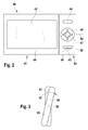
- FIG. 2 a first front view of a portable electronic device according to the invention
- FIG. 3 a representation of the rotation of the control unit relative to the display unit in a side view of the portable electronic device according to the Figures 2 or 4
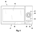
- FIG. 4 a second front view of a portable electronic device according to the invention with a compared to the FIG. 2 rotated 180 degrees control unit relative to the display unit.
- a portable electronic device 1 is shown schematically.
- the portable electronic device is designed, for example, as a portable small computer, for example as a so-called PDA (personal digital assistant).
- the portable electronic device 1 has a display unit 2 and an operation unit 3.
- the operating unit 3 is arranged so as to be rotatable relative to the display unit 2 about a rotation axis 4.
- a bearing 5 is provided between the display unit 2 and the control unit 3, which is also shown in dashed lines.
- the bearing 5 is preferably designed such that a locking of the control unit 3 relative to the display unit 2 is possible, so that for releasing the latch torque must be expended, which is increased compared to another rotation of the display unit 2 relative to the control unit 3 ,
- a latching is provided in particular for a position in which the side edges and the surfaces of each of the operating unit 3 and the display unit 2 continuously merge into one another.
- two positions of the operating unit 3 with respect to the display unit 2 are highlighted by the latching function, wherein the two positions differ by a rotation angle of 180 degrees.
- a camera 6 and a keypad 7 are arranged on two opposite sides of the control unit 3.
- the keypad 7 has only a push button in a first embodiment.
- the keypad 7 has a first pushbutton 8, a second pushbutton 9 and a rocker switch 10 with a central pushbutton element 11.
- the operating unit 3 can have on the side of the camera 6, for example, a flash lamp 12 and / or a sensor element 13, for example a range finder and / or a light meter.
- a memory unit 14 and / or a voltage source 15 are provided in one embodiment.
- the memory unit 14 and the voltage source 15 are preferably arranged in such an embodiment in the operating unit 3, in which the operating unit 3 is designed to be detachable from the display unit 2.
- the display unit 2 has a display surface 20, which is embodied, for example, as a liquid crystal display. In one embodiment, the display surface 20 may also be embodied as a touch-sensitive touch-screen surface over the touch of which a control of the display unit 2 is possible. Furthermore, the display unit 2 has a computing unit 21, which in particular serves to control the display area 20. In the arithmetic unit 21, one or more program blocks may be stored, which serve a function of the portable electronic device according to the functionalities of the program blocks. For example, a first program block 22 is provided which serves to store the images captured by the camera 6 in the memory unit 14 or in a memory unit 24 in the display unit. According to the program block 22, the captured images can also be displayed in the display area 20.
- a time is also stored along with the image data. A time determination can be carried out, for example, by the arithmetic unit 21.
- a program block 23 is provided in which a navigation function is integrated. By a corresponding input of a user, a destination can be specified.
- the arithmetic unit 21 may be a Determining travel route from a predetermined starting point to a destination and represent the route in the display area 20.
- the display unit has a position determination device 25, which is designed, for example, as a GPS position determination unit. Via a radio reception from several satellites, it is possible via such a satellite position determination unit to determine a position of the portable electronic device 1 on the earth. Thus, starting from the determined position, for example, a travel route to an entered destination can be determined.
- the position-determining device 25 may also be arranged in the operating unit 3.
- a position determination via the locating unit 25 in the case of an image acquisition by the camera 6, for example a recording of a still image, triggered for example via the central printing element 11.
- the position determined in this way is stored together with the recorded image data in the memory unit 14 and / or in the memory unit 24. If no locating is possible at the time of the recording, a last determined position can also be stored together with the time of the last position determination. Time information can also be obtained, for example, from the satellite signal of the satellite positioning system.
- the display unit 2 has a power supply unit 26, for example an accumulator.
- a switching element 27, 28 can be arranged on the display unit 2 and / or on the operating unit 3, which triggers upon rotation of the operating unit 3 relative to the display unit 2 from a rest position.
- a camera functionality can thereby be started.
- the camera 6 takes an image that is displayed automatically in the display area 20.
- a recorded image can then be stored in a memory 24, 14.
- the switching element 27, 28 can also for the realization a locking function of the display unit 2 relative to the control unit 3 are used.
- the arithmetic unit 21 has a program block 29, according to which a driver monitoring is carried out.
- the portable electronic device 1 is used for example in a holder in a vehicle and the operating unit 3 is rotated relative to the display unit 2 so that the camera 6 can observe a driver of the vehicle.
- the captured image of the driver is processed by the arithmetic unit 21.
- the head position or opening the eyes of the driver can be monitored.
- the recorded images are compared with predetermined image information regarding the driver's head positions or the eyes. If it is determined that the driver's head falls forward or the eyes close more than usual, a warning sound can be output to the driver via a loudspeaker 30.
- FIG. 2 An embodiment of a portable electronic device 40 is shown in a front view.
- an operating unit 43 On a display unit 41 with a display surface 42, an operating unit 43 is arranged, which has a first key 44, a second key 45, a cross-rocker 46 and arranged in the cross-rocker 46 central pushbutton 47.
- the operating unit 43 is adjusted relative to the display unit 41 so that a surface 48 of the operating unit 43 with the keys 44, 45, 46, 47 connects to a surface 49 of the display unit 41 with the display surface 42.
- FIG. 3 In a view on a narrow side 50 of the electronic device, a movement of the operating unit 43 relative to the display unit 41 in an arrow direction 51 is shown.
- the operating unit 43 is now compared to the arrangement according to the FIG. 2 rotated 180 degrees relative to the display unit 41.
- a surface 54 of the operating unit 43 which faces the surface 48, now adjoins the surface 49 of the display unit 41.
- a flash device 55, a camera lens 56 and sensors 57, 58 are arranged.
- image recordings of, for example, a viewer of the display surface 42 can now be made.
- the operating unit 43 can be rotated endlessly around the axis of rotation 52 in any direction. In a further embodiment, it can also be removed from the display unit 41.
- the outputs of a navigation device can be displayed, for example a directional arrow or a map display.
- image data recorded by the camera can also be displayed in the display area 42.
- PDA Personal Digital Assistant
- other functions of a so-called PDA such as a word processing or a scheduling, can be displayed in the display area 42.
Landscapes
- Engineering & Computer Science (AREA)
- Radar, Positioning & Navigation (AREA)
- Remote Sensing (AREA)
- Physics & Mathematics (AREA)
- Theoretical Computer Science (AREA)
- General Physics & Mathematics (AREA)
- Computer Hardware Design (AREA)
- General Engineering & Computer Science (AREA)
- Human Computer Interaction (AREA)
- Automation & Control Theory (AREA)
- Mathematical Physics (AREA)
- Signal Processing (AREA)
- Telephone Function (AREA)
- Studio Devices (AREA)
- Navigation (AREA)
Abstract
Description
- Die Erfindung geht aus von einem tragbaren elektronischen Gerät nach der Gattung des unabhängigen Anspruchs. Aus der
US 2006/0105806 A1 ist bereits ein Mobiltelefon bekannt, in das eine Kamera integriert ist. Hierzu ist ein kleiner Teil des Mobiltelefons derart drehbar ausgeführt, dass nach einem Bewegen eines Riegels ein an der Schmalseite des Mobiltelefons angeordnetes Kameraobjektiv freigegeben wird. Der drehbare Teil des Mobiltelefon-Gehäuses mit dem seitlich angeordneten Kameraobjektiv und drei an der Breitseite des Telefons angeordneten Tasten des Telefon-Tastenfeldes kann nun gedreht werden. - Das erfindungsgemäße tragbare elektronische Gerät mit den Merkmalen des unabhängigen Anspruchs hat demgegenüber den Vorteil, dass benachbart zu einer Anzeigeeinheit eine drehbare Bedieneinheit vorgesehen ist, bei der wenigstens eine Drucktaste und die Kamera auf jeweils gegenüberliegenden Seiten der drehbar angeordneten Bedieneinheit angeordnet sind. Indem sich eine Ausrichtung des Kameraobjektivs und eine Bedienungsoberfläche gegenüber liegen, wird die Bedienung für einen Benutzer erleichtert. Insbesondere wird es möglich, die an der Bedieneinheit angeordnete Drucktaste zu betrachten, während die auf der gegenüberliegenden Seite angeordnete Kamera auf ein Zielobjekt gerichtet ist.
- Durch die in den Unteransprüchen aufgeführten Maßnahmen sind vorteilhafte Weiterbildungen und Verbesserungen des in dem Hauptanspruch angegebenen tragbaren elektronischen Geräts möglich. Es ist insbesondere vorteilhaft, alle Drucktasten des tragbaren elektronischen Geräts an der Bedieneinheit auf der der Kamera gegenüberliegenden Seite anzuordnen, da hierdurch die gesamte Fläche der Anzeigeeinheit für eine Darstellung genutzt werden kann. Zudem ist eine übersichtliche Trennung zwischen Anzeige- und Bedienfunktionalitäten möglich. Durch die drehbare Anordnung kann zudem ein Benutzer die Drucktasten so drehen, dass eine bequeme Bedienung der Drucktasten für ihn möglich ist.
- Es ist ferner vorteilhaft, die wenigstens eine Drucktaste derart an der Bedieneinheit anzuordnen, dass eine Drehposition der Bedieneinheit gegenüber der Anzeigeeinheit besteht, an der eine Oberfläche, an der die Drucktaste angeordnet ist, bündig, d. h. ohne eine Stufe, in eine Oberfläche übergeht, an der eine Anzeigefläche der Anzeigeeinheit angeordnet ist. Hierbei sind in einer vorteilhaften Ausführung sowohl die wenigstens eine Drucktaste, bzw. in einer weiteren Ausführungsform alle Drucktasten, sowie die Anzeigeeinheit an einer Breitseite des tragbaren elektronischen Geräts angeordnet, wenn eine solche Drehstellung der Bedieneinheit gegenüber der Anzeigeeinheit eingestellt ist. In diesem Zustand kann sowohl vorteilhaft die Anzeige betrachtet, das Gerät auf eine ebene Fläche gelegt und die Bedieneinheit betätigt werden.
- Es ist ferner vorteilhaft, die Bedieneinheit von der Anzeigeeinheit abnehmbar anzuordnen. Hierdurch kann einerseits die Anzeigeeinheit ohne die Bedieneinheit verwendet werden, beispielsweise zur Bilddarstellung. Ferner kann auch die Bedieneinheit mit der Kamera abgenommen werden, falls beispielsweise Bildaufnahmen gemacht werden sollen, die Anzeigeeinheit aber nicht benötigt wird. Die Bedieneinheit mit der Kamera kann dann ohne Gefährdung der Anzeigeeinheit getrennt von dieser mitgeführt werden.
- Ferner ist es vorteilhaft, eine Schalteinheit vorzusehen, die automatisch die Kamera bei einem Verdrehen der Bedieneinheit aus einer vorgegebenen Ruhelage gegenüber der Anzeigeeinheit aktiviert. Hierdurch kann auf eine gesonderte Aktivierung der Kamera verzichtet werden. Nach einer vorgegebenen Zeit kann für den Fall, dass keine Bildauslösung erfolgt, die Kamera auch wieder automatisch abgeschaltet werden.
- Um Aufnahmen bei Dunkelheit zu erleichtern bzw. um insbesondere eine Belichtungsmessung durchzuführen, sind vorteilhaft neben der Kamera eine Blitzlichteinrichtung und/oder Sensoren insbesondere zur Helligkeitsmessung angeordnet.
- In einer vorteilhaften Ausgestaltung ist das tragbare Gerät insbesondere zu einer Fahrtroutenberechnung zu einem Fahrziel oder auch zu einer Fahrerüberwachung in einem Fahrzeug ausgelegt. Die Fahrerüberwachung ist dabei vorteilhaft durch die integrierte Kamera möglich, ohne dass eine Verbindung zu weiteren Messelementen zur Fahrerüberwachung erforderlich ist.
- Vorteilhaft ist das tragbare elektronische Gerät mit einer Halterung derart versehen, dass das elektronische Gerät lösbar in einem Fahrzeug befestigt werden kann, so dass die Funktionalitäten des tragbaren elektronischen Geräts auch während einer Fahrt zur Verfügung stehen. Dabei ist das tragbare elektronische Gerät auch während der Fahrt so angeordnet, dass es bei einer plötzlichen Beschleunigungseinwirkung gesichert ist.
- In einer vorteilhaften Ausführungsform ist zudem die Anzeigeeinheit als ein Touch-Screen-Bildschirm ausgeführt, so dass neben einer Steuerung über die Drucktasten der Bedieneinheit auch eine Steuerung des tragbaren elektronischen Geräts über die Anzeigefläche der Anzeigeeinheit möglich ist.
- In einer weiteren vorteilhaften Ausgestaltung weist das tragbare elektronische Gerät eine Positionsbestimmungseinheit beispielsweise in Form einer GPS-Positionsbestimmungseinheit auf. Über eine solche insbesondere satellitengestützte Positionsbestimmung kann die aktuelle Position des tragbaren elektronischen Geräts ermittelt werden. Eine entsprechende Positionsbestimmung kann beispielsweise für eine Fahrtroutenbestimmung verwendet werden. Ferner ist es auch möglich, für den Fall, dass eine Bildaufnahme mit der Kamera durchgeführt wird, zusammen mit der Bildinformation eine Positions-Information zu speichern. Hierdurch ist es später nachvollziehbar, an welcher Stelle ein gespeichertes Bild mit dem tragbaren elektronischen Gerät aufgenommen wurde.
- Kurze Beschreibung der Zeichnungen
- Ausführungsbeispiele der Erfindung sind in den Zeichnungen dargestellt und in der nachfolgenden Beschreibung näher erläutert.
- Es zeigen:
Figur 1 eine schematische Darstellung eines erfindungsgemäßen tragbaren elektronischen Geräts,Figur 2 eine erste Frontansicht eines erfindungsgemäßen tragbaren elektronischen Geräts,Figur 3 eine Darstellung der Drehung der Bedieneinheit gegenüber der Anzeigeeinheit in einer seitlichen Ansicht des tragbaren elektronischen Geräts gemäß derFiguren 2 bzw. 4 undFigur 4
eine zweite Frontansicht eines erfindungsgemäßen tragbaren elektronischen Geräts mit einer im Vergleich zu derFigur 2 um 180 Grad gedrehten Bedieneinheit gegenüber der Anzeigeeinheit. - In der
Figur 1 ist ein tragbares elektronisches Gerät 1 schematisch dargestellt. Das tragbare elektronische Gerät ist beispielsweise als ein tragbarer Kleincomputer ausgeführt, z.B. als ein sogenannter PDA (personal digital assistent). Das tragbare elektronische Gerät 1 weist eine Anzeigeeinheit 2 und eine Bedieneinheit 3 auf. Die Bedieneinheit 3 ist gegenüber der Anzeigeeinheit 2 um eine Drehachse 4 drehbar angeordnet. Hierzu ist zwischen der Anzeigeeinheit 2 und der Bedieneinheit 3 eine Lagerung 5 vorgesehen, die ebenfalls gestrichelt dargestellt ist. Die Lagerung 5 ist dabei bevorzugt derart ausgeführt, dass ein Einrasten der Bedieneinheit 3 gegenüber der Anzeigeeinheit 2 möglich ist, sodass für ein Lösen der Verrastung ein Drehmoment aufgewendet werden muss, das im Vergleich zu einer sonstigen Drehung der Anzeigeeinheit 2 gegenüber der Bedieneinheit 3 erhöht ist. Ein Einrasten ist insbesondere für eine Position vorgesehen, bei der die Seitenkanten und die Oberflächen jeweils der Bedieneinheit 3 und der Anzeigeeinheit 2 stufenlos ineinander übergehen. Damit sind zwei Stellungen der Bedieneinheit 3 gegenüber der Anzeigeeinheit 2 durch die Einrastfunktion hervorgehoben, wobei sich die beiden Positionen um einen Drehwinkel von 180 Grad unterscheiden. - An zwei gegenüberliegenden Seiten der Bedieneinheit 3 sind eine Kamera 6 und ein Tastenfeld 7 angeordnet. Insbesondere sind die Kamera 6 und das Tastenfeld 7 an einer Breitseite der Bedieneinheit 3 angeordnet. Das Tastenfeld 7 weist in einer ersten Ausführungsform lediglich eine Drucktaste auf. In der hier gezeigten Ausführungsform weist das Tastenfeld 7 eine erste Drucktaste 8, eine zweite Drucktaste 9 sowie eine Wipptaste 10 mit einem zentralen Drucktasten-Element 11 auf. Ferner kann die Bedieneinheit 3 in weiteren Ausführungsformen auf der Seite der Kamera 6 beispielsweise eine Blitzlampe 12 und/oder ein Sensorelement 13 aufweisen, beispielsweise einen Entfernungsmesser und/oder einen Belichtungsmesser. In der Bedieneinheit 3 selbst sind in einer Ausführungsform eine Speichereinheit 14 und/oder eine Spannungsquelle 15 vorgesehen. Die Speichereinheit 14 und die Spannungsquelle 15 sind bevorzugt bei einer solchen Ausführungsform in der Bedieneinheit 3 angeordnet, bei der die Bedieneinheit 3 von der Anzeigeeinheit 2 abnehmbar ausgeführt ist.
- Die Anzeigeeinheit 2 weist eine Anzeigefläche 20 auf, die beispielsweise als eine Flüssigkristallanzeige ausführt ist. In einer Ausführungsform kann die Anzeigefläche 20 auch als eine berührungsempfindliche Touch-Screen-Oberfläche ausgeführt sein, über deren Berührung eine Steuerung der Anzeigeeinheit 2 möglich ist. Ferner weist die Anzeigeeinheit 2 eine Recheneinheit 21 auf, die insbesondere der Steuerung der Anzeigefläche 20 dient. In der Recheneinheit 21 können ein oder mehrere Programmblöcke abgelegt sein, die entsprechend den Funktionalitäten der Programmblöcke einer Funktion des tragbaren elektronischen Geräts dienen. So ist beispielsweise ein erster Programmblock 22 vorgesehen, der einer Speicherung der von der Kamera 6 aufgenommenen Bilder in der Speichereinheit 14 bzw. in einer Speichereinheit 24 in der Anzeigeeinheit dient. Entsprechend dem Programmblock 22 können die aufgenommenen Bilder auch in der Anzeigefläche 20 dargestellt werden. Vorteilhaft wird zusammen mit den Bilddaten bevorzugt auch eine Uhrzeit mit abgespeichert. Eine Zeitermittlung kann beispielsweise durch die Recheneinheit 21 erfolgen.
- In einer weiteren Ausführungsform ist ein Programmblock 23 vorgesehen, in den eine Navigationsfunktion integriert ist. Durch eine entsprechende Eingabe eines Benutzers kann ein Fahrziel vorgegeben werden. Die Recheneinheit 21 kann eine Fahrroute von einem vorgegebenen Startpunkt zu einem Fahrziel bestimmen und die Fahrtroute in der Anzeigefläche 20 darstellen.
- In einer weiteren Ausführungsform weist die Anzeigeeinheit eine Positionsbestimmungseinrichtung 25 auf, die beispielsweise als eine GPS-Positionsbestimmungseinheit ausgeführt ist. Über einen Funkempfang von mehreren Satelliten ist es über eine derartige Satelliten-Positionsbestimmungseinheit möglich, eine Position des tragbaren elektronischen Geräts 1 auf der Erde zu bestimmen. Somit kann ausgehend von der bestimmten Position beispielsweise auch eine Fahrroute zu einem eingegebenen Fahrziel bestimmt werden. In einer alternativen Ausführungsform kann die Positionsbestimmungseinrichtung 25 auch in der Bedieneinheit 3 angeordnet sein.
- In einer weiteren Ausführungsform ist es möglich, bei einer beispielsweise über das zentrale Druckelement 11 ausgelösten Bildaufnahme durch die Kamera 6, beispielsweise eine Aufnahme eines Standbildes, auch eine Positionsbestimmung über die Ortungseinheit 25 durchzuführen. Die auf diese Weise ermittelte Position wird zusammen mit den aufgenommenen Bilddaten in der Speichereinheit 14 und/oder in der Speichereinheit 24 abgelegt. Ist zu dem jeweiligen Zeitpunkt der Aufnahme keine Ortung möglich, kann auch eine zuletzt ermittelte Position zusammen mit der Uhrzeit der letzten Positionsbestimmung abgespeichert werden. Eine Zeitinformation kann beispielsweise auch aus dem Satellitensignal des Satellitenortungssystems gewonnen werden. Zur Spannungsversorgung weist die Anzeigeeinheit 2 eine Spannungsversorgungseinheit 26 auf, beispielsweise einen Akkumulator.
- In einer Ausführungsform kann an der Anzeigeeinheit 2 und/oder an der Bedieneinheit 3 ein Schaltelement 27, 28 angeordnet sein, das bei einem Drehen der Bedieneinheit 3 gegenüber der Anzeigeeinheit 2 aus einer Ruhelage auslöst. In einer ersten Ausführungsform kann hierdurch eine Kamerafunktionalität gestartet werden. Hierbei nimmt die Kamera 6 ein Bild auf, dass in der Anzeigefläche 20 automatisch dargestellt wird. Bei einer Betätigung einer entsprechenden Drucktaste in dem Tastenfeld 7 kann dann ein aufgenommenes Bild in einem Speicher 24, 14 abgelegt werden. Das Schaltelement 27, 28 kann zudem zur Realisierung einer Einrastfunktion der Anzeigeeinheit 2 gegenüber der Bedieneinheit 3 verwendet werden.
- In einer weiteren Ausführungsform weist die Recheneinheit 21 einen Programmblock 29 auf, gemäß dem eine Fahrerüberwachung durchgeführt wird. Hierzu wird das tragbare elektronische Gerät 1 beispielsweise in einer Halterung in einem Fahrzeug so eingesetzt und die Bedieneinheit 3 gegenüber der Anzeigeeinheit 2 so gedreht, dass die Kamera 6 einen Fahrer des Fahrzeugs beobachten kann. Das aufgenommene Bild des Fahrers wird von der Recheneinheit 21 verarbeitet. Hierzu kann beispielsweise die Kopfposition oder ein Öffnen der Augen des Fahrers überwacht werden. Die aufgenommenen Bilder werden hierzu mit vorgegebenen Bildinformationen bezüglich der Fahrer-Kopfpositionen oder der Augen verglichen. Wird ermittelt, dass der Kopf des Fahrers nach vorne fällt oder die Augen mehr als gewöhnlich schließen, kann über einen Lautsprecher 30 ein Warnton an den Fahrer ausgegeben werden.
- In der
Figur 2 ist ein Ausführungsbeispiel für ein tragbares elektronisches Gerät 40 in einer Frontansicht gezeigt. An einer Anzeigeeinheit 41 mit einer Anzeigefläche 42 ist eine Bedieneinheit 43 angeordnet, die eine erste Taste 44, eine zweite Taste 45, eine Kreuzwippe 46 und eine in der Kreuzwippe 46 angeordnete zentrale Drucktaste 47 aufweist. In derFigur 2 ist die Bedieneinheit 43 gegenüber der Anzeigeeinheit 41 so eingestellt, dass eine Oberfläche 48 der Bedieneinheit 43 mit den Tasten 44, 45, 46, 47 an eine Oberfläche 49 der Anzeigeeinheit 41 mit der Anzeigefläche 42 anschließt. - In der
Figur 3 ist in einer Ansicht auf eine Schmalseite 50 des elektronischen Geräts eine Bewegung der Bedieneinheit 43 gegenüber der Anzeigeeinheit 41 in einer Pfeilrichtung 51 dargestellt. Bei einer Drehung in die Pfeilrichtung 51 um 180 Grad um eine Drehachse 52, die in derFigur 2 strichpunktiert gezeigt ist, ergibt sich eine Darstellung des tragbaren elektronischen Geräts 40 gemäß derFigur 4 . Die Bedieneinheit 43 ist nunmehr im Vergleich zu Anordnung gemäß derFigur 2 gegenüber der Anzeigeeinheit 41 um 180 Grad gedreht. Eine Oberfläche 54 der Bedieneinheit 43, die der Oberfläche 48 gegenüberliegt, schließt nunmehr an die Oberfläche 49 der Anzeigeeinheit 41 an. An dieser Oberfläche sind eine Blitzlichteinrichtung 55, ein Kameraobjektiv 56 und Sensoren 57, 58 angeordnet. Mit dem Objektiv 56 können entsprechend nun Bildaufnahmen beispielsweise eines Betrachters der Anzeigefläche 42 vorgenommen werden. - Die Bedieneinheit 43 kann in einer Ausführungsform um die Drehachse 52 in beliebige Richtung endlos gedreht werden. In einer weiteren Ausführungsform kann sie auch von der Anzeigeeinheit 41 abgenommen werden.
- In der Anzeigefläche 42 sind insbesondere die Ausgaben einer Navigationsvorrichtung darstellbar, beispielsweise ein Richtungspfeil oder eine Kartendarstellung. Ferner können auch von der Kamera aufgenommene Bilddaten in der Anzeigefläche 42 dargestellt werden. Außerdem können auch weitere Funktionen eines sogenannten PDA (Personal Digital Assistant), wie beispielsweise eine Textverarbeitung oder eine Terminplanung, in der Anzeigefläche 42 dargestellt werden.
Claims (10)
- Tragbares elektronisches Gerät (1, 40) mit einer Anzeigeeinheit (2, 41) und mit einer mit der Anzeigeeinheit (2, 41) verbundenen Bedieneinheit (3, 43), die gegenüber der Anzeigeeinheit (2, 41) drehbar gelagert ist, wobei die Bedieneinheit (3, 43) wenigstens eine Drucktaste (8, 9, 10, 11, 44, 45, 56, 47) und eine Kamera (6, 56) aufweist, dadurch gekennzeichnet, dass die Kamera (6, 56) auf einer der wenigstens einen Drucktaste (8, 9, 10, 11, 44, 45, 56, 47) gegenüberliegenden Seite (54) der Bedieneinheit (3, 43) angeordnet ist.
- Tragbares elektronisches Gerät nach Anspruch 1, dadurch gekennzeichnet, dass die wenigstens eine Drucktaste (8, 9, 10, 11, 44, 45, 56, 47) so an der Bedieneinheit (3, 43) angeordnet ist, dass die Bedieneinheit (3, 43) derart gedreht werden kann, dass eine Oberfläche (48), an der die wenigstens eine Drucktaste (8, 9, 10, 11, 44, 45, 56, 47) der Bedieneinheit (3, 43) angeordnet ist, stufenlos in eine Oberfläche (49) übergeht, an der eine Anzeigefläche (20, 42) der Anzeigeeinheit (2, 41) angeordnet ist.
- Tragbares elektronisches Gerät nach einem der vorhergehenden Ansprüche, dadurch gekennzeichnet, dass alle Drucktasten (8, 9, 10, 11, 44, 45, 56, 47) des tragbaren elektronischen Geräts (1, 40) an der Bedieneinheit (3, 43) auf der der Kamera (6, 56) gegenüberliegenden Seite (48) angeordnet sind.
- Tragbares elektronisches Gerät nach einem der vorhergehenden Ansprüche, dadurch gekennzeichnet, dass die Bedieneinheit (3, 43) von der Anzeigeeinheit (2, 41) abnehmbar an der Anzeigeeinheit (2, 41) angeordnet ist.
- Tragbares elektronisches Gerät nach einem der vorhergehenden Ansprüche, gekennzeichnet durch eine Schalteinheit (27, 28, 29) zur automatischen Aktivierung der Kamera (6, 56) bei einem Verdrehen der Bedieneinheit (3, 43) gegenüber der Anzeigeeinheit (2, 41).
- Tragbares elektronisches Gerät nach einem der vorhergehenden Ansprüche, gekennzeichnet durch eine Blitzlichteinrichtung (12, 55) und/oder eine Sensoreinrichtung (13, 57, 58), die neben der Kamera (6, 56) an der Bedieneinheit (3, 43) angeordnet sind.
- Tragbares elektronisches Gerät nach einem der vorhergehenden Ansprüche, gekennzeichnet durch eine Positionsbestimmungseinrichtung (25).
- Tragbares elektronisches Gerät nach einem der vorhergehenden Ansprüche, gekennzeichnet durch eine Recheneinheit (21) zur Fahrtroutenberechnung und/oder zur Fahrerüberwachung.
- Tragbares elektronisches Gerät nach einem der vorhergehenden Ansprüche, gekennzeichnet durch eine Halterung zur lösbaren Befestigung des tragbaren elektronischen Geräts (1, 40) in einem Fahrzeug.
- Tragbares elektronisches Gerät nach einem der vorhergehenden Ansprüche, dadurch gekennzeichnet, dass die Anzeigenoberfläche (20, 42) der Anzeigeeinheit (2, 41) als ein Touch-Screen-Bildschirm ausgeführt ist.
Applications Claiming Priority (1)
| Application Number | Priority Date | Filing Date | Title |
|---|---|---|---|
| DE200710031559 DE102007031559A1 (de) | 2007-07-06 | 2007-07-06 | Tragbares elektronisches Gerät |
Publications (1)
| Publication Number | Publication Date |
|---|---|
| EP2012505A1 true EP2012505A1 (de) | 2009-01-07 |
Family
ID=39790939
Family Applications (1)
| Application Number | Title | Priority Date | Filing Date |
|---|---|---|---|
| EP08103900A Withdrawn EP2012505A1 (de) | 2007-07-06 | 2008-05-09 | Tragbares elektronisches Gerät |
Country Status (3)
| Country | Link |
|---|---|
| EP (1) | EP2012505A1 (de) |
| CN (1) | CN101340472A (de) |
| DE (1) | DE102007031559A1 (de) |
Families Citing this family (1)
| Publication number | Priority date | Publication date | Assignee | Title |
|---|---|---|---|---|
| CN204859341U (zh) * | 2015-08-11 | 2015-12-09 | 深圳遨乐科技有限公司 | 一种fancam带转轴迷你运动相机 |
Citations (4)
| Publication number | Priority date | Publication date | Assignee | Title |
|---|---|---|---|---|
| EP0731589A2 (de) * | 1995-03-07 | 1996-09-11 | Siemens Aktiengesellschaft | Mobil betreibbares Kommunikationsgerät |
| EP1564968A1 (de) * | 2002-11-20 | 2005-08-17 | Matsushita Electric Industrial Co., Ltd. | Tragbares kommunikationsendgeraet |
| US20060105806A1 (en) | 2004-11-15 | 2006-05-18 | Vance Scott L | Mobile device with selectable camera position |
| US20070099656A1 (en) * | 2003-12-26 | 2007-05-03 | Lg Electronics Inc. | Portable terminal having digital camera function |
-
2007
- 2007-07-06 DE DE200710031559 patent/DE102007031559A1/de not_active Withdrawn
-
2008
- 2008-05-09 EP EP08103900A patent/EP2012505A1/de not_active Withdrawn
- 2008-07-04 CN CNA2008101282743A patent/CN101340472A/zh active Pending
Patent Citations (4)
| Publication number | Priority date | Publication date | Assignee | Title |
|---|---|---|---|---|
| EP0731589A2 (de) * | 1995-03-07 | 1996-09-11 | Siemens Aktiengesellschaft | Mobil betreibbares Kommunikationsgerät |
| EP1564968A1 (de) * | 2002-11-20 | 2005-08-17 | Matsushita Electric Industrial Co., Ltd. | Tragbares kommunikationsendgeraet |
| US20070099656A1 (en) * | 2003-12-26 | 2007-05-03 | Lg Electronics Inc. | Portable terminal having digital camera function |
| US20060105806A1 (en) | 2004-11-15 | 2006-05-18 | Vance Scott L | Mobile device with selectable camera position |
Also Published As
| Publication number | Publication date |
|---|---|
| DE102007031559A1 (de) | 2009-01-08 |
| CN101340472A (zh) | 2009-01-07 |
Similar Documents
| Publication | Publication Date | Title |
|---|---|---|
| DE102004005816B4 (de) | Kraftfahrzeug | |
| DE19955890B4 (de) | Verfahren und Vorrichtung zur Ausgabe von Bedienhinweisen | |
| EP0567660B2 (de) | Einrichtung zum Führen von Fahrzeugen | |
| EP1678002B1 (de) | Drehknopf für ein kraftfahrzeug | |
| DE102008046278B4 (de) | In der Hand gehaltene elektronische Einrichtung mit bewegungsgesteuerter Anzeige | |
| DE102006061597A1 (de) | Einparkunterstützungsvorrichtung | |
| WO2009059829A1 (de) | Navigationseinrichtung | |
| DE10226644A1 (de) | Eingabegerät für eine Datenverarbeitungsanlage | |
| DE3211234A1 (de) | Verfahren zum feststellen einer scharfeinstellung eines objektivs eines optischen geraetes | |
| EP1794021A1 (de) | Bedienelement für ein kraftfahrzeug | |
| EP1263620B1 (de) | Eingabevorrichtung an einer sonnenblende | |
| DE112017000819T5 (de) | Kamera | |
| EP3682296B1 (de) | Fernsteuerung für kameras | |
| EP2193953A2 (de) | Bedieneinrichtung und Verfahren zur Bedienung | |
| DE102015112605A1 (de) | System zum bestimmen eines kupplungswinkels | |
| DE112013006423B4 (de) | Fahrzeugbedienungssystem und Informationseinrichtung | |
| WO2001008409A1 (de) | Mobiles bildtelefon | |
| DE102007031559A1 (de) | Tragbares elektronisches Gerät | |
| DE102006038676A1 (de) | Fahrzeugnavigationssystem | |
| DE4345274C5 (de) | Navigationseinrichtung | |
| EP0130290A1 (de) | Navigationseinrichtung | |
| EP1739943A1 (de) | Mobiles Datenverarbeitungs-Handgerät | |
| DE102009038427A1 (de) | Bedienelement | |
| DE102005008566A1 (de) | Sichtgerät für Kraftfahrzeuge | |
| DE4217795C2 (de) | Videokamera |
Legal Events
| Date | Code | Title | Description |
|---|---|---|---|
| PUAI | Public reference made under article 153(3) epc to a published international application that has entered the european phase |
Free format text: ORIGINAL CODE: 0009012 |
|
| AK | Designated contracting states |
Kind code of ref document: A1 Designated state(s): AT BE BG CH CY CZ DE DK EE ES FI FR GB GR HR HU IE IS IT LI LT LU LV MC MT NL NO PL PT RO SE SI SK TR |
|
| AX | Request for extension of the european patent |
Extension state: AL BA MK RS |
|
| 17P | Request for examination filed |
Effective date: 20090707 |
|
| 17Q | First examination report despatched |
Effective date: 20090805 |
|
| AKX | Designation fees paid |
Designated state(s): AT BE BG CH CY CZ DE DK EE ES FI FR GB GR HR HU IE IS IT LI LT LU LV MC MT NL NO PL PT RO SE SI SK TR |
|
| STAA | Information on the status of an ep patent application or granted ep patent |
Free format text: STATUS: THE APPLICATION IS DEEMED TO BE WITHDRAWN |
|
| 18D | Application deemed to be withdrawn |
Effective date: 20100216 |