EP2012402A2 - Améliorations associées aux relais de protection de différentiel de courant - Google Patents
Améliorations associées aux relais de protection de différentiel de courant Download PDFInfo
- Publication number
- EP2012402A2 EP2012402A2 EP08159309A EP08159309A EP2012402A2 EP 2012402 A2 EP2012402 A2 EP 2012402A2 EP 08159309 A EP08159309 A EP 08159309A EP 08159309 A EP08159309 A EP 08159309A EP 2012402 A2 EP2012402 A2 EP 2012402A2
- Authority
- EP
- European Patent Office
- Prior art keywords
- protection relay
- current
- protection
- fault condition
- operating
- Prior art date
- Legal status (The legal status is an assumption and is not a legal conclusion. Google has not performed a legal analysis and makes no representation as to the accuracy of the status listed.)
- Granted
Links
Images




Classifications
-
- H—ELECTRICITY
- H02—GENERATION; CONVERSION OR DISTRIBUTION OF ELECTRIC POWER
- H02H—EMERGENCY PROTECTIVE CIRCUIT ARRANGEMENTS
- H02H3/00—Emergency protective circuit arrangements for automatic disconnection directly responsive to an undesired change from normal electric working condition with or without subsequent reconnection ; integrated protection
- H02H3/26—Emergency protective circuit arrangements for automatic disconnection directly responsive to an undesired change from normal electric working condition with or without subsequent reconnection ; integrated protection responsive to difference between voltages or between currents; responsive to phase angle between voltages or between currents
- H02H3/28—Emergency protective circuit arrangements for automatic disconnection directly responsive to an undesired change from normal electric working condition with or without subsequent reconnection ; integrated protection responsive to difference between voltages or between currents; responsive to phase angle between voltages or between currents involving comparison of the voltage or current values at two spaced portions of a single system, e.g. at opposite ends of one line, at input and output of apparatus
- H02H3/286—Emergency protective circuit arrangements for automatic disconnection directly responsive to an undesired change from normal electric working condition with or without subsequent reconnection ; integrated protection responsive to difference between voltages or between currents; responsive to phase angle between voltages or between currents involving comparison of the voltage or current values at two spaced portions of a single system, e.g. at opposite ends of one line, at input and output of apparatus involving comparison of similar homopolar quantities
-
- H—ELECTRICITY
- H02—GENERATION; CONVERSION OR DISTRIBUTION OF ELECTRIC POWER
- H02H—EMERGENCY PROTECTIVE CIRCUIT ARRANGEMENTS
- H02H3/00—Emergency protective circuit arrangements for automatic disconnection directly responsive to an undesired change from normal electric working condition with or without subsequent reconnection ; integrated protection
- H02H3/006—Calibration or setting of parameters
Definitions
- This invention relates in particular, but not exclusively, to a method of operating a current differential protection relay that is electrically coupled to a protection zone of an electrical power system, methods of protecting a protection zone of various electrical power systems having current differential protection relays electrical coupled thereto, and a current differential protection relay.
- the protection zone may include transmission lines having two terminal ends or, for example, one or more transformers, busbars, or motors.
- the electrical elements mentioned above are essential components of an electrical power transmission system and may be protected using line current differential protection relays, each of which is electrically coupled to the electrical element via a current transformer. On detecting a fault a given protection relay trips to isolate the electrical element lying within the protection zone.
- One method which attempts to deal with the problems that occur when the current transformer becomes saturated involves reducing the sensitivity of an associated current differential protection relay on detection of current transformer saturation, thereby reducing the likelihood of spurious tripping of the protection relay.
- one drawback with this method is that reducing the sensitivity of the protection relay also reduces the ability of the protection relay to detect a fault requiring isolation of the protection zone, thus reducing the reliability of the protection relay.
- a current differential protection relay following a fault the protection relay being electrically coupled to a protection zone of an electrical power system, comprising the steps of:
- Modifying the sensitivity of the protection relay according to the nature of the fault condition allows the protection relay to adapt to the fault condition and so maintains the ability of the protection relay to identify faults requiring isolation, i.e. requiring tripping of the protection relay, while reducing the likelihood of spurious tripping. Consequently the protection relay is able to accommodate current transformer inaccuracies and considerable current transformer saturation while maintaining a desired degree of reliability.
- the first method of the invention includes further steps as defined in dependent Claims 2 to 16.
- a method of protecting a protection zone of an electrical power system having at least one current differential protection relay electrically coupled therewith comprising the step of operating the or each protection relay according to the steps set out in any of Claims 1 to 16.
- a third aspect of the invention there is provided a method of protecting a protection zone of a three phase electrical power system, the protection zone being defined by a group of three local current transformers lying at one end of the protection zone and a second group of three remote current transformers lying at another end of the protection zone, each current transformer being electrically coupled to a phase of the electrical power system and having a current differential protection relay electrically coupled thereto, the method comprising the step of operating each protection relay according to the steps set out in any of Claims 1 to 16.
- the third method of the invention includes further steps as defined in dependent Claims 19 to 24.
- Figure 1 shows a schematic view of a protection zone 8 in a three phase electrical power system.
- the protection zone 8 is defined by a first group of three, local current transformers, one for each phase, (only one local current transformer 25 is shown in Figure 1 ) lying at one end of the protection zone 8, and a second group of three, remote current transformers, one for each phase, (only one remote current transformer 27 is shown in Figure 1 ) lying at the other end of the protection zone.
- Each local current transformer 25 is electrically coupled to a protection relay (only one protection relay 10 is shown schematically in Figure 1 ), and each remote current transformer 27 is electrically coupled to a further protection relay (only one further protection relay 26 is identified in Figure 1 ).
- Each protection relay 10, 26 has the same configuration as the protection relay 10 shown in Figure 1 .
- the three protection relays 10, 26 for the three phases at a given end of the protection zone may be combined into a single relay module (not shown) having three separate "relay phases" which function in the same way as discrete protection relays.
- the protection relay for each phase will be considered as a discrete element throughout the remainder of this text.
- each protection relay 10 includes a conventional signal conditioning module 12, digitizing module 14, phasor estimation module 16, and a bias characteristic module 18.
- each protection relay 10 includes a fault discriminator module 20, a sensitivity modifying module 22, and an index generating module 24.
- each fault discriminator module 20 establishes a fault condition by discriminating between an internal fault inside the protection zone and an external fault outside the protection zone.
- Establishing a fault condition includes evaluating the change with time of an operating characteristic of the corresponding protection relay 10 in a bias-differential current plane, as shown in Figure 2 .
- the trajectory of the protection relay's operating characteristic in the bias-differential current plane i.e. the way the protection relay's operating point in the bias-differential current plane changes with time, differs for internal and external faults.
- a discrete Fourier transform (DFT) filter is used to extract the phasor details of the operating characteristic, and preferably a one-cycle DFT filter is used for this phasor estimation.
- DFT discrete Fourier transform
- Such a filter provides four sample points for the operating characteristic from a load point to a fault point if the current transformer is not saturated, as shown in plot A for an internal fault and plot B for an external fault. If the current transformer is saturated then the operating characteristic will continue to change as the estimated phasor changes due to various levels of saturation in the subsequent cycles of the faulted waveform, as shown in plot C for an internal fault and plot D for an external fault.
- a preferred sampling frequency for the DFT filter is 48 samples per cycle, although other embodiments of the invention may use a different sampling frequency.
- the protection relays 10 coupled to the local current transformers 25 and the further protection relays 26 coupled to the remote current transformers 27 communicate with one another at a frequency of 4 times per cycle. In other embodiments however, the protection relays 10, 26 may communicate with one another at a different frequency.
- the fault discriminator module 20 establishes an internal fault condition when the first ratio is great than or equal to a first threshold value, which is preferably 1, or the second ratio is greater than or equal to a second threshold value, which is preferably 0.8.
- the fault discriminator module 20 establishes an external fault condition when the first ratio is less than a third threshold value, which is preferably 0.6, and an internal fault condition was not established during the preceding calculation cycle.
- the first, second and third threshold values are predetermined according to the nature of the electrical power system, including factors such as the operating conditions and dimensioning of the current transformers.
- the sampling frequency 48 samples per cycle in the embodiment described
- the frequency at which the protection relays 10, 26 communicate with one another 4 times per cycle in the embodiment described
- establishing a fault condition also includes a validation step in which an internal or external fault condition is only established if the first change in bias current is greater than a first design threshold value, or the first change in differential current is greater than a second design threshold value.
- Such validation is desirable as it avoids operation of the protection relay 10, i.e. tripping of the protection relay 10, during normal load variation and so helps to maintain the security of the electrical power system.
- the first design threshold is determined according to, A ⁇ fs fc where,
- the first and second design thresholds may differ from those outlined above.
- establishing a fault condition further includes a confirmation step in which an internal fault condition is only established when the first ratio is greater than or equal to the first threshold value or the second ratio is greater than or equal to the second threshold value, and the first change in bias current is greater than a first design threshold value or the first change in differential current is greater than a second design threshold value for two consecutive calculation cycles.
- Establishing a fault condition also includes re-establishing a fault condition following a predetermined delay.
- the fault discriminator module 20 may reset the fault condition if, for example, a "no-decision'' state, i.e. neither an internal fault condition or an external fault condition is established, is continuously present for 100ms.
- the fault discriminator module 20 may also reset the fault condition in the case of an external fault being established if the no-decision state is continuously present for 100ms.
- the fault discriminator module 20 may change the fault condition to an external fault condition if an external fault is established continuously for 60ms.
- the fault discriminator 20 may also change an external fault condition to an internal fault condition if an internal fault condition is established continuously for 40ms.
- the delay periods may differ to those set out above.
- Including the step of re-establishing a fault condition following a predetermined delay allows the protection relay to react quickly to changes in the fault condition in order to correctly trip in the event of a further subsequent fault requiring such action.
- the sensitivity modifying module 22 modifies the sensitivity of the protection relay 10, 26 according to the nature of the fault condition.
- Modifying the sensitivity of the protection relay 10, 26 includes increasing the sensitivity following establishment of an internal fault condition, and decreasing the sensitivity following establishment of an external fault condition.
- Increasing the sensitivity of the protection relay 10, 26 includes reducing the angle of inclination of a bias characteristic slope 28 of the protection relay 10, 26, as shown in Figure 6 for example.
- Reducing the sensitivity of the protection relay 10, 26 includes increasing the angle of inclination of the bias characteristic slope 28 of the protection relay 10, 26, as shown in Figure 7(a) for example.
- the magnitude of the signal sampled by the protection relay 10, 26 may be reduced which would normally make it difficult for the protection relay 10, 26 to determine whether tripping, i.e. isolation of the current transformer, is required.
- Increasing the sensitivity of the protection relay 10, 26, as outlined above, helps overcome this problem.
- the method of the invention described further includes tripping the protection relay 10, 26 if an operating characteristic of the protection relay 10, 26 enters a trigger region 30 which lies above the bias characteristic slope 28.
- the method of the invention described further includes inhibiting tripping of the protection relay 10, 26 that establishes the external fault condition.
- the method described also includes steps to vary the extent to which the sensitivity of the protection relay 10, 26 is modified according to the magnitude of an index value.
- Generating the index value is done according to the extent to which a sampled protection relay 10, 26 input current signal deviates from a predetermined waveform.
- the index value is only generated when the phasor magnitude is greater than a third design threshold value, which is preferably 0.01I n . This avoids the problem of the index value being very large for small levels of current which the sampling device has difficulty resolving.
- An index value is calculated by a corresponding protection relay 10, 26 for each phase and is communicated to the other protection relays 10, 26 together with the phasor magnitude and phase angle.
- a lower limit of 0 is applied to the angle of inclination of the two portions K1, K2 of the bias characteristic slopes for each pair of protection relays 10, 26 of a given phase. This is in order to avoid having negative bias characteristic slopes.
- the input signal and the estimated phasors from the output of the phasor estimation module 16 in the protection relay 10 electrically coupled to the local current transformer 25 for one phase, and the protection relay 26 electrically coupled to the remote current transformer 27 for the same phase is shown in Figure 3 . Only one phase (the "A" phase) is shown for clarity since the input signal and the outputs for the other phases B and C would be the same for faults involving them.
- Each of the local and remote current transformers 25, 27 arc dimensioned high enough, i.e. are sufficiently large, to avoid saturation.
- Figure 4 shows the plot of the index value and the modified portions K1, K2 of the bias characteristic slope 28.
- the index value plotted is the sum of the index values of the pair of protection relays 10, 26 in the A phase, and is used to modify the angle of inclination of the slope portions K1, K2. Since the current signals have a very high DC offset after the fault, the calculated index value reaches a maximum value of around 1 and then reduces with time as the DC component in the current signal decays.
- the fault discriminator module 20 establishes an internal fault condition the angle of inclination of the slope portions K1, K2 is reduced by the index value. However, the reduced slope of portion K1 was negative, and so it is limited to zero.
- Figure 5 shows the output of the fault discriminator module 20, a bias-differential comparator which determines whether the operating characteristic of the protection relay 10, 26 enters the trigger region 30 above the bias characteristic slope 28, and the final trip output.
- the fault discriminator module 20 establishes an internal fault condition within half a cycle of the fault inception and the final trip is generated within three-quarters of a cycle of the fault inception.
- Figure 6 shows the bias characteristic slope 28 along with the operating characteristic of the protection relay 10, 26.
- the angle of inclination of the two portions of the bias characteristic slope 28 is reduced following fault inception by an amount based on the index value.
- Figures 7(a) and 7(b) show the bias characteristic slope 28 along with the operating characteristic of the protection relay 10, 26.
- the fault discriminator module 20 establishes an external fault condition, and so the angle of inclination of each portion of the bias characteristic slope 28 is increased, according to the index value, after the fault inception.
- the operating characteristic of the protection relay 10, 26 remains below the surface of the bias characteristic slope 28 and so the protection relay 10, 26 does not trip.
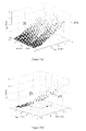
- Figures 8(a) and 8(b) show that the sensitivity of the protection relay 10, 26 is reduced by increasing the angle of inclination of each portion of the bias characteristic slope 28 following establishment of an external fault condition.
- the operating characteristic of the protection relay 10, 26 remains below the surface of the bias characteristic slope and so the protection relay 10, 26 does not trip.
- Figure 9 shows the bias characteristic slope 28 along with the operating characteristic of the protection relay 10, 26.
- the fault discriminator module 20 establishes an internal fault condition, and so increases the sensitivity of the protection relay by decreasing the angle of inclination of each portion of the bias characteristic slope 28 according to the index value.
- the operating characteristic of the protection relay 10, 26 enters the trigger region 30 and so a trip is generated.
Landscapes
- Engineering & Computer Science (AREA)
- Power Engineering (AREA)
- Emergency Protection Circuit Devices (AREA)
- Protection Of Transformers (AREA)
Applications Claiming Priority (1)
| Application Number | Priority Date | Filing Date | Title |
|---|---|---|---|
| GBGB0713126.1A GB0713126D0 (en) | 2007-07-06 | 2007-07-06 | Improvements in or relating to current differential protection relays |
Publications (3)
| Publication Number | Publication Date |
|---|---|
| EP2012402A2 true EP2012402A2 (fr) | 2009-01-07 |
| EP2012402A3 EP2012402A3 (fr) | 2014-06-04 |
| EP2012402B1 EP2012402B1 (fr) | 2015-05-20 |
Family
ID=38440498
Family Applications (1)
| Application Number | Title | Priority Date | Filing Date |
|---|---|---|---|
| EP20080159309 Not-in-force EP2012402B1 (fr) | 2007-07-06 | 2008-06-30 | Améliorations associées aux relais de protection de différentiel de courant |
Country Status (5)
| Country | Link |
|---|---|
| US (1) | US7906970B2 (fr) |
| EP (1) | EP2012402B1 (fr) |
| CN (1) | CN101340078B (fr) |
| CA (1) | CA2636977C (fr) |
| GB (1) | GB0713126D0 (fr) |
Cited By (3)
| Publication number | Priority date | Publication date | Assignee | Title |
|---|---|---|---|---|
| WO2010121660A1 (fr) * | 2009-04-24 | 2010-10-28 | Abb Research Ltd | Procédé et dispositif de supervision de la sensibilité d'une fonction de protection |
| WO2017129233A1 (fr) * | 2016-01-27 | 2017-08-03 | Abb Schweiz Ag | Procédé et dispositif de commande pour protection différentielle de courant |
| EP4333228A1 (fr) * | 2022-08-30 | 2024-03-06 | Hitachi Energy Ltd | Discrimination adaptative de défaut pour une protection différentielle de ligne |
Families Citing this family (16)
| Publication number | Priority date | Publication date | Assignee | Title |
|---|---|---|---|---|
| CN101576601B (zh) * | 2009-06-16 | 2011-08-03 | 重庆大学 | 数字式变压器保护装置测量回路的隐藏故障诊断方法 |
| US8634175B2 (en) * | 2011-04-13 | 2014-01-21 | Siemens Industry, Inc. | Method and system for programming and implementing automated fault isolation and restoration using sequential logic |
| RU2550152C1 (ru) * | 2011-05-19 | 2015-05-10 | Абб Текнолоджи Аг | Система и способ защиты электрической энергосистемы |
| RU2580934C1 (ru) * | 2012-06-06 | 2016-04-10 | Абб Текнолоджи Лтд. | Способ и устройство для идентификации короткого замыкания посредством дифференциальной токовой защиты |
| US10871513B2 (en) | 2012-11-26 | 2020-12-22 | Siemens Aktiengesellschaft | Differential protection method in an electrical power supply system and protective apparatus for carrying out a differential protection method |
| EP2984719B1 (fr) * | 2013-04-07 | 2020-05-27 | ABB Power Grids Switzerland AG | Procédé de détection de défaut et système de protection différentielle de courant associé |
| US20150301101A1 (en) * | 2014-04-22 | 2015-10-22 | King Fahd University Of Petroleum And Minerals | Adaptive pmu-based fault location method for series-compensated lines |
| CN104242268B (zh) * | 2014-09-11 | 2017-06-16 | 国电南瑞科技股份有限公司 | 一种三区域电流差动保护方法 |
| CN104502795B (zh) * | 2014-11-26 | 2017-11-14 | 国家电网公司 | 一种适用于微电网的智能故障诊断方法 |
| US9777723B2 (en) * | 2015-01-02 | 2017-10-03 | General Electric Company | System and method for health management of pumping system |
| CN104682360B (zh) * | 2015-01-22 | 2018-05-22 | 南京南瑞继保电气有限公司 | 一种识别电流互感器饱和的方法及装置 |
| CN107064689B (zh) * | 2017-05-02 | 2019-10-22 | 许继电气股份有限公司 | 一种变压器ta断线的模拟方法及系统 |
| CN111638427B (zh) * | 2020-06-03 | 2021-05-28 | 西南交通大学 | 一种基于核胶囊神经元覆盖的变压器故障检测方法 |
| US11469588B2 (en) * | 2020-08-31 | 2022-10-11 | Schweitzer Engineering Laboratories, Inc. | Electric power system differential protection with DC compensation |
| US12149063B2 (en) | 2022-09-28 | 2024-11-19 | Schneider Electric (Australia) Pty Ltd. | System and method for restraining differential bias |
| CN115656724A (zh) * | 2022-10-31 | 2023-01-31 | 中国南方电网有限责任公司 | 一种双端差动电流故障判定方法、系统、电子设备及介质 |
Family Cites Families (6)
| Publication number | Priority date | Publication date | Assignee | Title |
|---|---|---|---|---|
| US3609523A (en) * | 1969-04-02 | 1971-09-28 | Wayne Electronic Products Co | Automatic test apparatus for phase comparison protective relay systems and the like |
| JP2565870B2 (ja) * | 1986-06-11 | 1996-12-18 | 株式会社東芝 | 差動継電装置 |
| US6442010B1 (en) * | 2000-04-03 | 2002-08-27 | General Electric Company | Differential protective relay for electrical buses with improved immunity to saturation of current transformers |
| US6829544B1 (en) * | 2000-04-10 | 2004-12-07 | General Electric Company | Line current differential protective relaying method and relay for in-zone tapped transformers |
| SE0303615D0 (sv) * | 2003-12-31 | 2003-12-31 | Abb Ab | Method and device for Fault Detection in Transformers |
| CN101278452B (zh) * | 2005-08-30 | 2010-10-13 | Abb技术有限公司 | 用于电气设备中穿越故障检测的方法和系统 |
-
2007
- 2007-07-06 GB GBGB0713126.1A patent/GB0713126D0/en not_active Ceased
-
2008
- 2008-06-30 EP EP20080159309 patent/EP2012402B1/fr not_active Not-in-force
- 2008-07-03 CA CA2636977A patent/CA2636977C/fr not_active Expired - Fee Related
- 2008-07-03 US US12/167,479 patent/US7906970B2/en not_active Expired - Fee Related
- 2008-07-04 CN CN2008101282512A patent/CN101340078B/zh not_active Expired - Fee Related
Cited By (8)
| Publication number | Priority date | Publication date | Assignee | Title |
|---|---|---|---|---|
| WO2010121660A1 (fr) * | 2009-04-24 | 2010-10-28 | Abb Research Ltd | Procédé et dispositif de supervision de la sensibilité d'une fonction de protection |
| US8472156B2 (en) | 2009-04-24 | 2013-06-25 | Abb Research Ltd. | Method and device for supervising the sensitivity of a protection function |
| RU2496201C2 (ru) * | 2009-04-24 | 2013-10-20 | Абб Рисерч Лтд | Способ и устройство для контролирования чувствительности функции защиты |
| WO2017129233A1 (fr) * | 2016-01-27 | 2017-08-03 | Abb Schweiz Ag | Procédé et dispositif de commande pour protection différentielle de courant |
| CN108475913A (zh) * | 2016-01-27 | 2018-08-31 | Abb瑞士股份有限公司 | 用于电流差动保护的方法和控制设备 |
| US10243351B2 (en) | 2016-01-27 | 2019-03-26 | Abb Schweiz Ag | Method and control device for current differential protection |
| CN108475913B (zh) * | 2016-01-27 | 2020-06-16 | Abb瑞士股份有限公司 | 用于电流差动保护的方法和控制设备 |
| EP4333228A1 (fr) * | 2022-08-30 | 2024-03-06 | Hitachi Energy Ltd | Discrimination adaptative de défaut pour une protection différentielle de ligne |
Also Published As
| Publication number | Publication date |
|---|---|
| CN101340078A (zh) | 2009-01-07 |
| GB0713126D0 (en) | 2007-08-15 |
| US7906970B2 (en) | 2011-03-15 |
| CA2636977C (fr) | 2016-04-26 |
| CA2636977A1 (fr) | 2009-01-06 |
| EP2012402A3 (fr) | 2014-06-04 |
| EP2012402B1 (fr) | 2015-05-20 |
| US20090009181A1 (en) | 2009-01-08 |
| CN101340078B (zh) | 2013-01-23 |
Similar Documents
| Publication | Publication Date | Title |
|---|---|---|
| EP2012402B1 (fr) | Améliorations associées aux relais de protection de différentiel de courant | |
| US10823777B2 (en) | Detection and location of broken conductors for transmission lines | |
| US7180300B2 (en) | System and method of locating ground fault in electrical power distribution system | |
| US7196884B2 (en) | Apparatus and method for detecting the loss of a current transformer connection coupling a current differential relay to an element of a power system | |
| EP3563162B1 (fr) | Procédé et système de commande pour détection de phase défectueuse | |
| US7660088B2 (en) | System, apparatus and method for compensating the sensitivity of a sequence element in a line current differential relay in a power system | |
| EP1273083B1 (fr) | Relais de protection differentiel destine aux bus electriques a immunite amelioree a la saturation de transformateurs de courant | |
| EP2223404B1 (fr) | Détecteur de courant d'appel de transformateur | |
| EP2306609A2 (fr) | Détecteur de courant résiduel | |
| US9106076B2 (en) | Differential protection in electrical power networks | |
| EP2745367B1 (fr) | Procédé de protection de distance de lignes de transmission parallèles | |
| US6944554B2 (en) | Method for detecting fault on transmission lines by using harmonics and state transition diagram | |
| EP3639337B1 (fr) | Procédé et système de commande de détection de direction de défaillance | |
| US6914762B2 (en) | Protection of electrical power lines | |
| EP1313194A2 (fr) | Protection de lignes d'énergie à double circuit | |
| CN103954879A (zh) | 一种带并联电抗器同杆双回线故障性质判别方法 | |
| KR20040014364A (ko) | 지락 방향 계전 장치 | |
| US12130321B2 (en) | Fault detection in a power transmission system | |
| US10871513B2 (en) | Differential protection method in an electrical power supply system and protective apparatus for carrying out a differential protection method | |
| US20250321292A1 (en) | Method to detect single-phase-to-ground faults in electric power systems | |
| US20040090728A1 (en) | Current compensation method and device for power system protection | |
| KR100383720B1 (ko) | 송전선로의 아크사고 검출 및 고장거리 추정방법 | |
| EP0169313A1 (fr) | Relais de protection pour transformateur | |
| US6137666A (en) | High speed, selective protective relays | |
| KR100357494B1 (ko) | 고주파를 이용한 계전알고리즘의 최적 모달변환 선정방법및 이를 이용한 고장검출방법 |
Legal Events
| Date | Code | Title | Description |
|---|---|---|---|
| PUAI | Public reference made under article 153(3) epc to a published international application that has entered the european phase |
Free format text: ORIGINAL CODE: 0009012 |
|
| AK | Designated contracting states |
Kind code of ref document: A2 Designated state(s): AT BE BG CH CY CZ DE DK EE ES FI FR GB GR HR HU IE IS IT LI LT LU LV MC MT NL NO PL PT RO SE SI SK TR |
|
| AX | Request for extension of the european patent |
Extension state: AL BA MK RS |
|
| RAP1 | Party data changed (applicant data changed or rights of an application transferred) |
Owner name: AREVA T&D UK LTD. Owner name: SCHNEIDER ELECTRIC ENERGY UK LTD |
|
| RAP1 | Party data changed (applicant data changed or rights of an application transferred) |
Owner name: ALSTOM GRID UK LIMITED Owner name: SCHNEIDER ELECTRIC ENERGY UK LTD |
|
| RAP1 | Party data changed (applicant data changed or rights of an application transferred) |
Owner name: ALSTOM TECHNOLOGY LTD. Owner name: SCHNEIDER ELECTRIC ENERGY UK LTD |
|
| PUAL | Search report despatched |
Free format text: ORIGINAL CODE: 0009013 |
|
| AK | Designated contracting states |
Kind code of ref document: A3 Designated state(s): AT BE BG CH CY CZ DE DK EE ES FI FR GB GR HR HU IE IS IT LI LT LU LV MC MT NL NO PL PT RO SE SI SK TR |
|
| AX | Request for extension of the european patent |
Extension state: AL BA MK RS |
|
| RIC1 | Information provided on ipc code assigned before grant |
Ipc: H02H 3/28 20060101AFI20140425BHEP |
|
| GRAP | Despatch of communication of intention to grant a patent |
Free format text: ORIGINAL CODE: EPIDOSNIGR1 |
|
| 17P | Request for examination filed |
Effective date: 20141106 |
|
| RBV | Designated contracting states (corrected) |
Designated state(s): AT BE BG CH CY CZ DE DK EE ES FI FR GB GR HR HU IE IS IT LI LT LU LV MC MT NL NO PL PT RO SE SI SK TR |
|
| INTG | Intention to grant announced |
Effective date: 20141208 |
|
| AKX | Designation fees paid |
Designated state(s): AT BE BG CH CY CZ DE DK EE ES FI FR GB GR HR HU IE IS IT LI LT LU LV MC MT NL NO PL PT RO SE SI SK TR |
|
| GRAS | Grant fee paid |
Free format text: ORIGINAL CODE: EPIDOSNIGR3 |
|
| GRAA | (expected) grant |
Free format text: ORIGINAL CODE: 0009210 |
|
| AK | Designated contracting states |
Kind code of ref document: B1 Designated state(s): AT BE BG CH CY CZ DE DK EE ES FI FR GB GR HR HU IE IS IT LI LT LU LV MC MT NL NO PL PT RO SE SI SK TR |
|
| REG | Reference to a national code |
Ref country code: GB Ref legal event code: FG4D |
|
| REG | Reference to a national code |
Ref country code: CH Ref legal event code: EP |
|
| REG | Reference to a national code |
Ref country code: AT Ref legal event code: REF Ref document number: 728173 Country of ref document: AT Kind code of ref document: T Effective date: 20150615 |
|
| REG | Reference to a national code |
Ref country code: IE Ref legal event code: FG4D |
|
| REG | Reference to a national code |
Ref country code: DE Ref legal event code: R096 Ref document number: 602008038199 Country of ref document: DE Effective date: 20150702 |
|
| REG | Reference to a national code |
Ref country code: NL Ref legal event code: T3 |
|
| REG | Reference to a national code |
Ref country code: AT Ref legal event code: MK05 Ref document number: 728173 Country of ref document: AT Kind code of ref document: T Effective date: 20150520 |
|
| REG | Reference to a national code |
Ref country code: LT Ref legal event code: MG4D |
|
| PG25 | Lapsed in a contracting state [announced via postgrant information from national office to epo] |
Ref country code: NO Free format text: LAPSE BECAUSE OF FAILURE TO SUBMIT A TRANSLATION OF THE DESCRIPTION OR TO PAY THE FEE WITHIN THE PRESCRIBED TIME-LIMIT Effective date: 20150820 Ref country code: LT Free format text: LAPSE BECAUSE OF FAILURE TO SUBMIT A TRANSLATION OF THE DESCRIPTION OR TO PAY THE FEE WITHIN THE PRESCRIBED TIME-LIMIT Effective date: 20150520 Ref country code: PT Free format text: LAPSE BECAUSE OF FAILURE TO SUBMIT A TRANSLATION OF THE DESCRIPTION OR TO PAY THE FEE WITHIN THE PRESCRIBED TIME-LIMIT Effective date: 20150921 Ref country code: FI Free format text: LAPSE BECAUSE OF FAILURE TO SUBMIT A TRANSLATION OF THE DESCRIPTION OR TO PAY THE FEE WITHIN THE PRESCRIBED TIME-LIMIT Effective date: 20150520 Ref country code: ES Free format text: LAPSE BECAUSE OF FAILURE TO SUBMIT A TRANSLATION OF THE DESCRIPTION OR TO PAY THE FEE WITHIN THE PRESCRIBED TIME-LIMIT Effective date: 20150520 Ref country code: HR Free format text: LAPSE BECAUSE OF FAILURE TO SUBMIT A TRANSLATION OF THE DESCRIPTION OR TO PAY THE FEE WITHIN THE PRESCRIBED TIME-LIMIT Effective date: 20150520 |
|
| PG25 | Lapsed in a contracting state [announced via postgrant information from national office to epo] |
Ref country code: LV Free format text: LAPSE BECAUSE OF FAILURE TO SUBMIT A TRANSLATION OF THE DESCRIPTION OR TO PAY THE FEE WITHIN THE PRESCRIBED TIME-LIMIT Effective date: 20150520 Ref country code: IS Free format text: LAPSE BECAUSE OF FAILURE TO SUBMIT A TRANSLATION OF THE DESCRIPTION OR TO PAY THE FEE WITHIN THE PRESCRIBED TIME-LIMIT Effective date: 20150920 Ref country code: GR Free format text: LAPSE BECAUSE OF FAILURE TO SUBMIT A TRANSLATION OF THE DESCRIPTION OR TO PAY THE FEE WITHIN THE PRESCRIBED TIME-LIMIT Effective date: 20150821 Ref country code: BG Free format text: LAPSE BECAUSE OF FAILURE TO SUBMIT A TRANSLATION OF THE DESCRIPTION OR TO PAY THE FEE WITHIN THE PRESCRIBED TIME-LIMIT Effective date: 20150820 Ref country code: AT Free format text: LAPSE BECAUSE OF FAILURE TO SUBMIT A TRANSLATION OF THE DESCRIPTION OR TO PAY THE FEE WITHIN THE PRESCRIBED TIME-LIMIT Effective date: 20150520 |
|
| PG25 | Lapsed in a contracting state [announced via postgrant information from national office to epo] |
Ref country code: IT Free format text: LAPSE BECAUSE OF FAILURE TO SUBMIT A TRANSLATION OF THE DESCRIPTION OR TO PAY THE FEE WITHIN THE PRESCRIBED TIME-LIMIT Effective date: 20150520 Ref country code: EE Free format text: LAPSE BECAUSE OF FAILURE TO SUBMIT A TRANSLATION OF THE DESCRIPTION OR TO PAY THE FEE WITHIN THE PRESCRIBED TIME-LIMIT Effective date: 20150520 Ref country code: DK Free format text: LAPSE BECAUSE OF FAILURE TO SUBMIT A TRANSLATION OF THE DESCRIPTION OR TO PAY THE FEE WITHIN THE PRESCRIBED TIME-LIMIT Effective date: 20150520 |
|
| REG | Reference to a national code |
Ref country code: CH Ref legal event code: PL |
|
| REG | Reference to a national code |
Ref country code: DE Ref legal event code: R097 Ref document number: 602008038199 Country of ref document: DE |
|
| PG25 | Lapsed in a contracting state [announced via postgrant information from national office to epo] |
Ref country code: CZ Free format text: LAPSE BECAUSE OF FAILURE TO SUBMIT A TRANSLATION OF THE DESCRIPTION OR TO PAY THE FEE WITHIN THE PRESCRIBED TIME-LIMIT Effective date: 20150520 Ref country code: RO Free format text: LAPSE BECAUSE OF NON-PAYMENT OF DUE FEES Effective date: 20150520 Ref country code: SK Free format text: LAPSE BECAUSE OF FAILURE TO SUBMIT A TRANSLATION OF THE DESCRIPTION OR TO PAY THE FEE WITHIN THE PRESCRIBED TIME-LIMIT Effective date: 20150520 Ref country code: MC Free format text: LAPSE BECAUSE OF FAILURE TO SUBMIT A TRANSLATION OF THE DESCRIPTION OR TO PAY THE FEE WITHIN THE PRESCRIBED TIME-LIMIT Effective date: 20150520 Ref country code: PL Free format text: LAPSE BECAUSE OF FAILURE TO SUBMIT A TRANSLATION OF THE DESCRIPTION OR TO PAY THE FEE WITHIN THE PRESCRIBED TIME-LIMIT Effective date: 20150520 |
|
| REG | Reference to a national code |
Ref country code: IE Ref legal event code: MM4A |
|
| PLBE | No opposition filed within time limit |
Free format text: ORIGINAL CODE: 0009261 |
|
| STAA | Information on the status of an ep patent application or granted ep patent |
Free format text: STATUS: NO OPPOSITION FILED WITHIN TIME LIMIT |
|
| 26N | No opposition filed |
Effective date: 20160223 |
|
| PG25 | Lapsed in a contracting state [announced via postgrant information from national office to epo] |
Ref country code: LI Free format text: LAPSE BECAUSE OF NON-PAYMENT OF DUE FEES Effective date: 20150630 Ref country code: CH Free format text: LAPSE BECAUSE OF NON-PAYMENT OF DUE FEES Effective date: 20150630 Ref country code: IE Free format text: LAPSE BECAUSE OF NON-PAYMENT OF DUE FEES Effective date: 20150630 |
|
| PG25 | Lapsed in a contracting state [announced via postgrant information from national office to epo] |
Ref country code: SI Free format text: LAPSE BECAUSE OF FAILURE TO SUBMIT A TRANSLATION OF THE DESCRIPTION OR TO PAY THE FEE WITHIN THE PRESCRIBED TIME-LIMIT Effective date: 20150520 |
|
| REG | Reference to a national code |
Ref country code: FR Ref legal event code: PLFP Year of fee payment: 9 |
|
| PGFP | Annual fee paid to national office [announced via postgrant information from national office to epo] |
Ref country code: GB Payment date: 20160627 Year of fee payment: 9 |
|
| PG25 | Lapsed in a contracting state [announced via postgrant information from national office to epo] |
Ref country code: BE Free format text: LAPSE BECAUSE OF FAILURE TO SUBMIT A TRANSLATION OF THE DESCRIPTION OR TO PAY THE FEE WITHIN THE PRESCRIBED TIME-LIMIT Effective date: 20150520 |
|
| PGFP | Annual fee paid to national office [announced via postgrant information from national office to epo] |
Ref country code: FR Payment date: 20160628 Year of fee payment: 9 Ref country code: NL Payment date: 20160626 Year of fee payment: 9 |
|
| PGFP | Annual fee paid to national office [announced via postgrant information from national office to epo] |
Ref country code: DE Payment date: 20160628 Year of fee payment: 9 |
|
| PG25 | Lapsed in a contracting state [announced via postgrant information from national office to epo] |
Ref country code: MT Free format text: LAPSE BECAUSE OF FAILURE TO SUBMIT A TRANSLATION OF THE DESCRIPTION OR TO PAY THE FEE WITHIN THE PRESCRIBED TIME-LIMIT Effective date: 20150520 |
|
| PG25 | Lapsed in a contracting state [announced via postgrant information from national office to epo] |
Ref country code: HU Free format text: LAPSE BECAUSE OF FAILURE TO SUBMIT A TRANSLATION OF THE DESCRIPTION OR TO PAY THE FEE WITHIN THE PRESCRIBED TIME-LIMIT; INVALID AB INITIO Effective date: 20080630 |
|
| PG25 | Lapsed in a contracting state [announced via postgrant information from national office to epo] |
Ref country code: SE Free format text: LAPSE BECAUSE OF FAILURE TO SUBMIT A TRANSLATION OF THE DESCRIPTION OR TO PAY THE FEE WITHIN THE PRESCRIBED TIME-LIMIT Effective date: 20150520 Ref country code: CY Free format text: LAPSE BECAUSE OF FAILURE TO SUBMIT A TRANSLATION OF THE DESCRIPTION OR TO PAY THE FEE WITHIN THE PRESCRIBED TIME-LIMIT Effective date: 20150520 |
|
| PG25 | Lapsed in a contracting state [announced via postgrant information from national office to epo] |
Ref country code: TR Free format text: LAPSE BECAUSE OF FAILURE TO SUBMIT A TRANSLATION OF THE DESCRIPTION OR TO PAY THE FEE WITHIN THE PRESCRIBED TIME-LIMIT Effective date: 20150520 |
|
| PG25 | Lapsed in a contracting state [announced via postgrant information from national office to epo] |
Ref country code: LU Free format text: LAPSE BECAUSE OF NON-PAYMENT OF DUE FEES Effective date: 20150630 |
|
| REG | Reference to a national code |
Ref country code: DE Ref legal event code: R119 Ref document number: 602008038199 Country of ref document: DE |
|
| REG | Reference to a national code |
Ref country code: NL Ref legal event code: MM Effective date: 20170701 |
|
| GBPC | Gb: european patent ceased through non-payment of renewal fee |
Effective date: 20170630 |
|
| PG25 | Lapsed in a contracting state [announced via postgrant information from national office to epo] |
Ref country code: NL Free format text: LAPSE BECAUSE OF NON-PAYMENT OF DUE FEES Effective date: 20170701 |
|
| REG | Reference to a national code |
Ref country code: FR Ref legal event code: ST Effective date: 20180228 |
|
| PG25 | Lapsed in a contracting state [announced via postgrant information from national office to epo] |
Ref country code: GB Free format text: LAPSE BECAUSE OF NON-PAYMENT OF DUE FEES Effective date: 20170630 Ref country code: DE Free format text: LAPSE BECAUSE OF NON-PAYMENT OF DUE FEES Effective date: 20180103 |
|
| PG25 | Lapsed in a contracting state [announced via postgrant information from national office to epo] |
Ref country code: FR Free format text: LAPSE BECAUSE OF NON-PAYMENT OF DUE FEES Effective date: 20170630 |