EP2012139A1 - Vorrichtung und Verfahren zur Körperüberwachung - Google Patents
Vorrichtung und Verfahren zur Körperüberwachung Download PDFInfo
- Publication number
- EP2012139A1 EP2012139A1 EP07111887A EP07111887A EP2012139A1 EP 2012139 A1 EP2012139 A1 EP 2012139A1 EP 07111887 A EP07111887 A EP 07111887A EP 07111887 A EP07111887 A EP 07111887A EP 2012139 A1 EP2012139 A1 EP 2012139A1
- Authority
- EP
- European Patent Office
- Prior art keywords
- skin
- pulses
- distance
- antenna
- generator
- Prior art date
- Legal status (The legal status is an assumption and is not a legal conclusion. Google has not performed a legal analysis and makes no representation as to the accuracy of the status listed.)
- Withdrawn
Links
Images


Classifications
-
- G—PHYSICS
- G01—MEASURING; TESTING
- G01S—RADIO DIRECTION-FINDING; RADIO NAVIGATION; DETERMINING DISTANCE OR VELOCITY BY USE OF RADIO WAVES; LOCATING OR PRESENCE-DETECTING BY USE OF THE REFLECTION OR RERADIATION OF RADIO WAVES; ANALOGOUS ARRANGEMENTS USING OTHER WAVES
- G01S13/00—Systems using the reflection or reradiation of radio waves, e.g. radar systems; Analogous systems using reflection or reradiation of waves whose nature or wavelength is irrelevant or unspecified
- G01S13/66—Radar-tracking systems; Analogous systems
- G01S13/70—Radar-tracking systems; Analogous systems for range tracking only
-
- A—HUMAN NECESSITIES
- A61—MEDICAL OR VETERINARY SCIENCE; HYGIENE
- A61B—DIAGNOSIS; SURGERY; IDENTIFICATION
- A61B5/00—Measuring for diagnostic purposes; Identification of persons
- A61B5/05—Detecting, measuring or recording for diagnosis by means of electric currents or magnetic fields; Measuring using microwaves or radio waves
- A61B5/0507—Detecting, measuring or recording for diagnosis by means of electric currents or magnetic fields; Measuring using microwaves or radio waves using microwaves or terahertz waves
-
- A—HUMAN NECESSITIES
- A61—MEDICAL OR VETERINARY SCIENCE; HYGIENE
- A61B—DIAGNOSIS; SURGERY; IDENTIFICATION
- A61B5/00—Measuring for diagnostic purposes; Identification of persons
- A61B5/103—Detecting, measuring or recording devices for testing the shape, pattern, colour, size or movement of the body or parts thereof, for diagnostic purposes
- A61B5/11—Measuring movement of the entire body or parts thereof, e.g. head or hand tremor, mobility of a limb
- A61B5/113—Measuring movement of the entire body or parts thereof, e.g. head or hand tremor, mobility of a limb occurring during breathing
-
- G—PHYSICS
- G01—MEASURING; TESTING
- G01S—RADIO DIRECTION-FINDING; RADIO NAVIGATION; DETERMINING DISTANCE OR VELOCITY BY USE OF RADIO WAVES; LOCATING OR PRESENCE-DETECTING BY USE OF THE REFLECTION OR RERADIATION OF RADIO WAVES; ANALOGOUS ARRANGEMENTS USING OTHER WAVES
- G01S13/00—Systems using the reflection or reradiation of radio waves, e.g. radar systems; Analogous systems using reflection or reradiation of waves whose nature or wavelength is irrelevant or unspecified
- G01S13/02—Systems using reflection of radio waves, e.g. primary radar systems; Analogous systems
- G01S13/06—Systems determining position data of a target
- G01S13/08—Systems for measuring distance only
- G01S13/10—Systems for measuring distance only using transmission of interrupted, pulse modulated waves
- G01S13/18—Systems for measuring distance only using transmission of interrupted, pulse modulated waves wherein range gates are used
-
- G—PHYSICS
- G01—MEASURING; TESTING
- G01S—RADIO DIRECTION-FINDING; RADIO NAVIGATION; DETERMINING DISTANCE OR VELOCITY BY USE OF RADIO WAVES; LOCATING OR PRESENCE-DETECTING BY USE OF THE REFLECTION OR RERADIATION OF RADIO WAVES; ANALOGOUS ARRANGEMENTS USING OTHER WAVES
- G01S13/00—Systems using the reflection or reradiation of radio waves, e.g. radar systems; Analogous systems using reflection or reradiation of waves whose nature or wavelength is irrelevant or unspecified
- G01S13/02—Systems using reflection of radio waves, e.g. primary radar systems; Analogous systems
- G01S13/50—Systems of measurement based on relative movement of target
- G01S13/58—Velocity or trajectory determination systems; Sense-of-movement determination systems
- G01S13/581—Velocity or trajectory determination systems; Sense-of-movement determination systems using transmission of interrupted pulse modulated waves and based upon the Doppler effect resulting from movement of targets
-
- A—HUMAN NECESSITIES
- A61—MEDICAL OR VETERINARY SCIENCE; HYGIENE
- A61B—DIAGNOSIS; SURGERY; IDENTIFICATION
- A61B5/00—Measuring for diagnostic purposes; Identification of persons
- A61B5/02—Detecting, measuring or recording pulse, heart rate, blood pressure or blood flow; Combined pulse/heart-rate/blood pressure determination; Evaluating a cardiovascular condition not otherwise provided for, e.g. using combinations of techniques provided for in this group with electrocardiography or electroauscultation; Heart catheters for measuring blood pressure
- A61B5/024—Detecting, measuring or recording pulse rate or heart rate
-
- G—PHYSICS
- G01—MEASURING; TESTING
- G01S—RADIO DIRECTION-FINDING; RADIO NAVIGATION; DETERMINING DISTANCE OR VELOCITY BY USE OF RADIO WAVES; LOCATING OR PRESENCE-DETECTING BY USE OF THE REFLECTION OR RERADIATION OF RADIO WAVES; ANALOGOUS ARRANGEMENTS USING OTHER WAVES
- G01S13/00—Systems using the reflection or reradiation of radio waves, e.g. radar systems; Analogous systems using reflection or reradiation of waves whose nature or wavelength is irrelevant or unspecified
- G01S13/02—Systems using reflection of radio waves, e.g. primary radar systems; Analogous systems
- G01S13/0209—Systems with very large relative bandwidth, i.e. larger than 10 %, e.g. baseband, pulse, carrier-free, ultrawideband
Definitions
- the present invention concerns, in general, the medical field and more particularly a monitor and a method for detecting, monitoring and measuring the movements of internal body organs, such as heart, lungs, foetus, womb, etc.
- the present invention relates to a monitor and a method, as mentioned above, making use of an impulse radar system and comprising means to compensate for the movements as a whole of the body under monitoring.
- U.S. Patent No. 5,573,012 An impulse radar system for monitoring internal body organs is described in U.S. Patent No. 5,573,012 and its continuation in part U.S. Patent No. 5,766,208 .
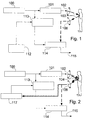
- UWB radar consisting of an UWB (Ultra Wide Band) impulse transmitter (made of a "Pseudo Random Binary Sequence" -or PBRS- generator 100, a pulse generator 101 and a transmit antenna 102), and an UWB pulse receiver comprising a receive antenna 106 and a boxcar averager (made of a voltage controlled delay generator 113, a reference level circuit 112 and a sampler and averager 114), synchronously locked to the emitted pulses with a phase shift proportional to the time delay of the pulse-echo path to the body organ (for instance the heart) wall to be tracked.
- UWB radar consisting of an UWB (Ultra Wide Band) impulse transmitter (made of a "Pseudo Random Binary Sequence" -
- the voltage controlled delay generator receives PRBS pulses as well as a fixed delay provided by reference level circuit 112 from which it generates a sampling window (or time gating pulse) that corresponds to the measuring range of the target echo signal. No compensation is provided for the movement of the entire body so that, if the body moves, tracking of the heart wall, or of any other internal organ of interest, is extremely difficult to achieve due to the additional noise (i.e. artefacts), which is introduced into the useful signal by body movement or even impossible to achieve if, for the same reason, the echo signal arrives outside the fixed sampling window.
- additional noise i.e. artefacts
- the system of the invention includes a skin echo detector that continuously detects and permits to compensate for the variations in the distance between the skin and the system antennas.
- the radar system also captures the early echo from the air-skin interface and makes use of it to estimate the distance to the body in real time and to adjust the time gating pulse accordingly.
- the skin echo detector adjusts the delay of the voltage controlled delay generator to correspond to the correct distance between the antennas and the body so as to maintain the tracking on the internal body organ wall of interest.
- the antenna-skin distance is estimated by detecting the skin echo, which is a very intense and early echo returning from the body.
- Fig. 2 shows a block diagram of a radar system in accordance with the principle of the present invention.
- the system of the invention provides a skin echo detector 117.
- the echo signal from the receive antenna 106 is supplied to such echo detector 117 and the latter applies its output signal, which is a function of the path 104 between the skin and antennas (102 and 106), to the control input of the controlled delay generator 113 so as to adjust the range gate, i.e. the sampling window for the sampler and averager 114. This adjustment will take care of the instantaneous distance between the antennas and the body.
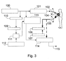
- FIG. 3 shows a first embodiment of the invention.
- the PRBS (Pseudo Random Binary Sequence) generator 100 produces a sequence of pulses with random varying interpulse period.
- the pulse sequence is made random - or pseudo-random - essentially for eliminating interference from other near RF (radio frequency) sources.
- the pulses are applied to the pulse generator 101 for producing UWB pulses (i.e. pulses of very short duration leading to a wide spectrum emitted radiation) to be radiated by the antenna 102. From the antenna the pulses can run on two paths.
- the shorter path 104 comprises skin reflection, while the longer path 103 considers penetration into the human body and reflection by the heart wall 105 (or any other internal organ of interest to be monitored). So the receiving antenna 106 will receive one very intense and early echo from the skin reflection and a subsequent weaker echo from the internal organ wall reflection.
- a skin echo detector is composed by a comparator 108, which outputs a signal when whatsoever echo signal is higher than a predefined reference voltage level supplied by a second reference level circuit 107.
- the output signal of the comparator samples the voltage level provided by the ramp generator 110 by means of the sample-and-hold circuit 109.
- This sampled voltage being proportional to the instantaneous distance between the skin and the antennas 102 and 106, is added by the adder 111 to a first reference voltage level provided by a first reference level circuit 112 for calibration, so that the resulting voltage is made directly proportional to the instantaneous distance of the heart wall to the antennas 102 and 106.
- This latter voltage is used to control the voltage controlled delay generator 113 for the operation of a boxcar averager, made of the sampler and averager circuit 114, to produce a final output signal 115.
- This final output signal is only proportional to the antenna-heart distance and will be further processed by processing means (not shown), such as a computer and display devices.
- Compensation of body movements is thus continuously made by the skin echo detector, so as to adapt the voltage controlled delay generator to the exact distance of the internal organ wall to the two antennas.
- Relative distance of the body organ wall to the skin is adjusted by varying the first reference voltage level of circuit 112 while relative distance of the skin to the antennas is controlled by the second reference voltage level 107.
- the ramp voltage signal out of the ramp generator is continuously reset to zero at each PRBS generator pulse.
- the first reference voltage level 112 can be negative so as to compensate even for excessive delay in response to the output signal of the comparator 108 which might happen even after the echo from the heart wall has arrived. In such a case, compensation will be effective on subsequent pulses, provided that the speed of movement of the body is very low with respect to the repetition frequency of pulses generated by the PRBS generator 100.
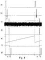
- Fig. 4 shows the different waveforms, which appear in the impulse radar system of Fig. 3 .
- Fig. 4.a shows PRBS pulses, as provided by PRBS generator 100. Typically, the average repetition frequency of these pulses is in the range of 1 to 10 MHz.
- Fig. 4.b shows UWB pulses generated by the pulse generator 101 from the pulses delivered by PRBS generator. As mentioned above, these pulses must have a short duration to cause the spectrum of the emitted radiation to be very large.
- Fig. 4.c shows the echo signal, as received by the receive antenna 106, which is applied to both the comparator circuit 108 and the sampler and averager circuit 114.
- the echo signal is strongly affected by noise except for peaks, which correspond to the echo signal from the skin surface and the amplitude of which is higher than the reference threshold voltage Tr that is used by the comparator circuit.
- the output signal of the comparator circuit shown in Fig. 4.d , is applied to the sample-and-hold circuit 109, which also receives the ramp voltage signal, shown in Fig. 4.e , delivered by the ramp generator 110. It must be noted that the ramp generator is reset by pulses generated by the PRBS generator 100.
- Fig. 4.f shows the output signal of circuit 109.
- the latency Ta between PRBS pulses and the signal of Fig. 4.f is representative of the distance between the skin and the antennas.
- a constant delay Tb given by the first reference level circuit 112 is added to Ta by the adder circuit 111 to generate a signal, shown in Fig. 4.g , which is applied to the voltage controlled delay generator 113.
- the latter can thus generate the sampling window for the target echo to be extracted by the sampler-and-averager circuit 114 from the echo signal ( Fig. 4.c ).
- Figure 5 shows a second embodiment of the present invention.
- the impulse radar system comprises the UWB pulse transmitter, as previously described, and a UWB pulse receiver consisting of a boxcar averager 114, synchronously locked to the emitted pulse with a phase shift, proportional to the time delay to the pulse-echo path to the heart (or lung) wall to be tracked.
- a skin echo detector has been added so as to detect in a continuous way and compensate for the variation in skin-antennas distance as follows:
- the skin echo detector of this second embodiment comprises a peak detector 116, the maximum amplitude of which is roughly proportional to the distance between the antenna and the skin of the patient, since the skin echo is supposed to be, not only the earliest echo signal but the one of the highest intensity.
- the signal out of the peak detector is adjusted to the correct compensation value, for the voltage controlled generator 113, by means of adder 111, which adds the output signal of said peak detector to the first reference voltage level provided by circuit 112.
- the resulting voltage is used to control the voltage controlled delay generator 113 for the operation of the boxcar averager, made of the sampler and averager circuit 114, to produce the final signal 115 out. This will only be proportional to the antennas-heart distance or M-mode heart wall signal.
- Fig. 6 shows the waveforms appearing at different points of the system of Fig. 5 .
- Figs. 6.a, 6.b and 6.c are identical to Figs. 4.a, 4.b and 4.c and therefore, will not be described again.
- Fig. 6.d shows a signal generated by the peak detector 116 and Fig. 6.e shows the output signal of this peak detector.
- the signal shown in Fig. 6.e exhibits a shift Ta with respect to PRBS pulses. Such shift corresponds to the path in the air between both antennas and the skin.
- an additional constant shift Tb is added to the delay Ta through the first reference level circuit 112 and the adder circuit 111.
- the output signal of the adder circuit is applied to the voltage controlled delay generator, which delivers an output signal shown in Fig. 6.f to the sampler-and-averager circuit 114.
- the signal produced by the latter circuit may be further processed by means known to anybody skilled in the art.
- FIG. 7 A possible implementation of the skin echo detector 117 of the first embodiment is shown in Figure 7 .
- the output of comparator 303 drives the sample-and-hold circuit 304 (made of the switch S1 and capacitor C2 [1.8nF]), which samples the ramp signal generated by the ramp generator 110.
- the latter comprises a constant current source 301 (transistor Q1 [PN3640] and resistors R1 [680 ⁇ ], R2 [82 ⁇ ], R3 [3.9k ⁇ ] and R5 [150 ⁇ ]) and a capacitor C1 [1.8nF].
- the output of sample-and-hold circuit 304 is added to the first reference level provided by circuit 305 (adjustable resistor VR1 [10k ⁇ ] and resistor R8 [1k ⁇ ]).
- the resulting signal is applied to the non-inverting input of the amplifier 306 [LM6132B].
- the ramp generator 110 is periodically reset by pulses from the PRBS generator through N-MOS transistor Q2 [BSH101]. When activated, the transistor Q2 rapidly discharges the capacitor C1, thus resetting said ramp generator.
- the output signal Vout can then drive the Voltage Controlled Delay Generator of Figure 3 .
- FIG. 8 Another implementation of the skin echo detector according to the second embodiment of the invention is shown in Figure 8 .
- Circuit 310 comprises an operational amplifier X2 [LM6132B] and a Schottky diode D1 [BAT85]. Schottky diodes are known to exhibit a very low direct voltage drop and a very fast switching time. The time constant of the circuit arrangement 311 is large enough, so that the voltage at the common node of capacitor C3 and resistor R10 is always above the noise level of the echo signal within the repetition period. As in figure 7 , the output signal of the peak detector is added to the second reference level provided by circuit 305 and the resulting signal is amplified by the amplifier 306.
- Exemplary applications of the present invention may include, without any limitation
Landscapes
- Engineering & Computer Science (AREA)
- Radar, Positioning & Navigation (AREA)
- Remote Sensing (AREA)
- Health & Medical Sciences (AREA)
- Life Sciences & Earth Sciences (AREA)
- Physics & Mathematics (AREA)
- Computer Networks & Wireless Communication (AREA)
- General Physics & Mathematics (AREA)
- Biomedical Technology (AREA)
- Animal Behavior & Ethology (AREA)
- Biophysics (AREA)
- Pathology (AREA)
- Veterinary Medicine (AREA)
- Heart & Thoracic Surgery (AREA)
- Medical Informatics (AREA)
- Molecular Biology (AREA)
- Surgery (AREA)
- Public Health (AREA)
- General Health & Medical Sciences (AREA)
- Radiology & Medical Imaging (AREA)
- Nuclear Medicine, Radiotherapy & Molecular Imaging (AREA)
- Physiology (AREA)
- Dentistry (AREA)
- Oral & Maxillofacial Surgery (AREA)
- Radar Systems Or Details Thereof (AREA)
Priority Applications (1)
| Application Number | Priority Date | Filing Date | Title |
|---|---|---|---|
| EP07111887A EP2012139A1 (de) | 2007-07-06 | 2007-07-06 | Vorrichtung und Verfahren zur Körperüberwachung |
Applications Claiming Priority (1)
| Application Number | Priority Date | Filing Date | Title |
|---|---|---|---|
| EP07111887A EP2012139A1 (de) | 2007-07-06 | 2007-07-06 | Vorrichtung und Verfahren zur Körperüberwachung |
Publications (1)
| Publication Number | Publication Date |
|---|---|
| EP2012139A1 true EP2012139A1 (de) | 2009-01-07 |
Family
ID=38722994
Family Applications (1)
| Application Number | Title | Priority Date | Filing Date |
|---|---|---|---|
| EP07111887A Withdrawn EP2012139A1 (de) | 2007-07-06 | 2007-07-06 | Vorrichtung und Verfahren zur Körperüberwachung |
Country Status (1)
| Country | Link |
|---|---|
| EP (1) | EP2012139A1 (de) |
Cited By (11)
| Publication number | Priority date | Publication date | Assignee | Title |
|---|---|---|---|---|
| WO2010099402A1 (en) * | 2009-02-27 | 2010-09-02 | PneumoSonics, Inc. | Non-invasive pneumothorax detection and apparatus |
| DE102009040198A1 (de) | 2009-09-07 | 2011-03-10 | Karlsruher Institut für Technologie | Radar Sensorik zur Überwachung von Flüssigkeitsansammlungen im menschlichen Körper |
| WO2013003510A1 (en) * | 2011-06-29 | 2013-01-03 | The Procter & Gamble Company | Apparatus and method for contactlessly monitoring the condition of a living subject using electromagnetic waves |
| JP2016080398A (ja) * | 2014-10-10 | 2016-05-16 | 株式会社日本ジー・アイ・ティー | 生体情報検出レーダ装置 |
| JPWO2017057524A1 (ja) * | 2015-09-29 | 2018-08-02 | 国立大学法人神戸大学 | 画像化方法および画像化装置 |
| WO2020082000A1 (en) * | 2018-10-18 | 2020-04-23 | Deep Science, Llc | Systems and methods for micro impulse radar detection of physiological information |
| US11299260B2 (en) | 2018-07-24 | 2022-04-12 | Deep Science, Llc | Systems and methods for active control of surface drag |
| US11466709B2 (en) | 2021-02-17 | 2022-10-11 | Deep Science, Llc | In-plane transverse momentum injection to disrupt large-scale eddies in a turbulent boundary layer |
| US11519433B2 (en) | 2018-11-06 | 2022-12-06 | Deep Science, Llc | Systems and methods for active control of surface drag using wall coupling |
| US11744157B2 (en) | 2018-11-30 | 2023-08-29 | Deep Science, Llc | Systems and methods of active control of surface drag using selective wave generation |
| US11905983B2 (en) | 2020-01-23 | 2024-02-20 | Deep Science, Llc | Systems and methods for active control of surface drag using electrodes |
Citations (5)
| Publication number | Priority date | Publication date | Assignee | Title |
|---|---|---|---|---|
| US4000490A (en) * | 1975-01-30 | 1976-12-28 | General Dynamics Corporation | Traveling range gate tracking system |
| JPH06217975A (ja) * | 1993-01-28 | 1994-08-09 | Toshiba Medical Eng Co Ltd | 超音波ドプラ診断装置 |
| US5573012A (en) * | 1994-08-09 | 1996-11-12 | The Regents Of The University Of California | Body monitoring and imaging apparatus and method |
| US6673020B2 (en) * | 2000-02-10 | 2004-01-06 | Aloka Co., Ltd. | Ultrasonic diagnostic apparatus |
| US20040249257A1 (en) * | 2003-06-04 | 2004-12-09 | Tupin Joe Paul | Article of manufacture for extracting physiological data using ultra-wideband radar and improved signal processing techniques |
-
2007
- 2007-07-06 EP EP07111887A patent/EP2012139A1/de not_active Withdrawn
Patent Citations (5)
| Publication number | Priority date | Publication date | Assignee | Title |
|---|---|---|---|---|
| US4000490A (en) * | 1975-01-30 | 1976-12-28 | General Dynamics Corporation | Traveling range gate tracking system |
| JPH06217975A (ja) * | 1993-01-28 | 1994-08-09 | Toshiba Medical Eng Co Ltd | 超音波ドプラ診断装置 |
| US5573012A (en) * | 1994-08-09 | 1996-11-12 | The Regents Of The University Of California | Body monitoring and imaging apparatus and method |
| US6673020B2 (en) * | 2000-02-10 | 2004-01-06 | Aloka Co., Ltd. | Ultrasonic diagnostic apparatus |
| US20040249257A1 (en) * | 2003-06-04 | 2004-12-09 | Tupin Joe Paul | Article of manufacture for extracting physiological data using ultra-wideband radar and improved signal processing techniques |
Cited By (14)
| Publication number | Priority date | Publication date | Assignee | Title |
|---|---|---|---|---|
| WO2010099402A1 (en) * | 2009-02-27 | 2010-09-02 | PneumoSonics, Inc. | Non-invasive pneumothorax detection and apparatus |
| DE102009040198A1 (de) | 2009-09-07 | 2011-03-10 | Karlsruher Institut für Technologie | Radar Sensorik zur Überwachung von Flüssigkeitsansammlungen im menschlichen Körper |
| WO2013003510A1 (en) * | 2011-06-29 | 2013-01-03 | The Procter & Gamble Company | Apparatus and method for contactlessly monitoring the condition of a living subject using electromagnetic waves |
| JP2016080398A (ja) * | 2014-10-10 | 2016-05-16 | 株式会社日本ジー・アイ・ティー | 生体情報検出レーダ装置 |
| JPWO2017057524A1 (ja) * | 2015-09-29 | 2018-08-02 | 国立大学法人神戸大学 | 画像化方法および画像化装置 |
| US11299260B2 (en) | 2018-07-24 | 2022-04-12 | Deep Science, Llc | Systems and methods for active control of surface drag |
| WO2020082000A1 (en) * | 2018-10-18 | 2020-04-23 | Deep Science, Llc | Systems and methods for micro impulse radar detection of physiological information |
| US11701020B2 (en) | 2018-10-18 | 2023-07-18 | Deep Science, Llc | Systems and methods for micro impulse radar detection of physiological information |
| US11519433B2 (en) | 2018-11-06 | 2022-12-06 | Deep Science, Llc | Systems and methods for active control of surface drag using wall coupling |
| US11744157B2 (en) | 2018-11-30 | 2023-08-29 | Deep Science, Llc | Systems and methods of active control of surface drag using selective wave generation |
| US11905983B2 (en) | 2020-01-23 | 2024-02-20 | Deep Science, Llc | Systems and methods for active control of surface drag using electrodes |
| US11466709B2 (en) | 2021-02-17 | 2022-10-11 | Deep Science, Llc | In-plane transverse momentum injection to disrupt large-scale eddies in a turbulent boundary layer |
| US11692566B2 (en) | 2021-02-17 | 2023-07-04 | Deep Science, Llc | In-plane transverse momentum injection to disrupt large-scale eddies in a turbulent boundary layer |
| US11933334B2 (en) | 2021-02-17 | 2024-03-19 | Enterprise Science Fund, Llc | In-plane transverse momentum injection to disrupt large-scale eddies in a turbulent boundary layer |
Similar Documents
| Publication | Publication Date | Title |
|---|---|---|
| EP2012139A1 (de) | Vorrichtung und Verfahren zur Körperüberwachung | |
| KR101908196B1 (ko) | Fmcw 레이더에서의 주파수 변조 방식 | |
| RU2369323C1 (ru) | Импульсный сверхширокополосный датчик | |
| US10610196B2 (en) | Shape injection into ultrasound image to calibrate beam patterns in real-time | |
| US20120146852A1 (en) | Pulse radar receiver | |
| CN111289966B (zh) | 基于mimo调频连续波雷达相干相位追踪的运动信息测量方法 | |
| JPH10505671A (ja) | 飛行時間による無線位置システム | |
| WO2007127886A2 (en) | Wireless localization apparatus and method | |
| JP2001198124A (ja) | 侵入力を高めるための音波フラッシュ | |
| CN107049361B (zh) | 使用剪切波的声音速度成像 | |
| JP6434006B2 (ja) | ハイライトシステム及び判定方法 | |
| CN108324262B (zh) | 用于动脉脉搏测量的方法和装置 | |
| US20110092819A1 (en) | Ultrasonic diagnosis apparatus and ultrasoinc data acquisition method | |
| EP2858574A1 (de) | Systeme und verfahren zur erkennung und darstellung von interventionsvorrichtungen durch ultraschallbildgebung | |
| US20220378394A1 (en) | Ultrasound diagnostic apparatus, control method of ultrasound diagnostic apparatus, and processor for ultrasound diagnostic apparatus | |
| CN106955125B (zh) | 声学辐射力脉冲成像中的运动无关性 | |
| EP3907523B1 (de) | Radarbasierte zielverfolgung unter verwendung von bewegungserkennung | |
| JPH1090398A (ja) | コンーレント特徴を有するロックされていないw帯域受信機 | |
| Antide et al. | Comparative study of radar architectures for human vital signs measurement | |
| EP2466332A2 (de) | Durchführung einer Empfangsstrahlformung basierend auf dem Mittenpunktalgorithmus in einem Ultraschallsystem | |
| EP3335056B1 (de) | Gekoppelter radar | |
| KR101971769B1 (ko) | 무선 임펄스 신호를 이용하여 생체신호를 측정하는 장치 및 방법 | |
| RU2392853C1 (ru) | Способ дистанционного определения параметров дыхания и сердцебиения | |
| GB2274560A (en) | Echo pulse detection circuit | |
| RU2392852C2 (ru) | Импульсный сверхширокополосный датчик дистанционного мониторинга дыхания и сердцебиения |
Legal Events
| Date | Code | Title | Description |
|---|---|---|---|
| PUAI | Public reference made under article 153(3) epc to a published international application that has entered the european phase |
Free format text: ORIGINAL CODE: 0009012 |
|
| AK | Designated contracting states |
Kind code of ref document: A1 Designated state(s): AT BE BG CH CY CZ DE DK EE ES FI FR GB GR HU IE IS IT LI LT LU LV MC MT NL PL PT RO SE SI SK TR |
|
| AX | Request for extension of the european patent |
Extension state: AL BA HR MK RS |
|
| AKX | Designation fees paid | ||
| REG | Reference to a national code |
Ref country code: DE Ref legal event code: 8566 |
|
| STAA | Information on the status of an ep patent application or granted ep patent |
Free format text: STATUS: THE APPLICATION IS DEEMED TO BE WITHDRAWN |
|
| 18D | Application deemed to be withdrawn |
Effective date: 20090708 |