EP2012075B1 - Refrigeration device - Google Patents
Refrigeration device Download PDFInfo
- Publication number
- EP2012075B1 EP2012075B1 EP07741717.8A EP07741717A EP2012075B1 EP 2012075 B1 EP2012075 B1 EP 2012075B1 EP 07741717 A EP07741717 A EP 07741717A EP 2012075 B1 EP2012075 B1 EP 2012075B1
- Authority
- EP
- European Patent Office
- Prior art keywords
- oil
- compressor
- casing
- expander
- refrigerant
- Prior art date
- Legal status (The legal status is an assumption and is not a legal conclusion. Google has not performed a legal analysis and makes no representation as to the accuracy of the status listed.)
- Active
Links
- 238000005057 refrigeration Methods 0.000 title claims description 189
- 239000003507 refrigerant Substances 0.000 claims description 251
- 239000000314 lubricant Substances 0.000 claims description 138
- 230000007246 mechanism Effects 0.000 claims description 121
- 238000007906 compression Methods 0.000 claims description 73
- 230000006835 compression Effects 0.000 claims description 68
- 230000001105 regulatory effect Effects 0.000 claims description 56
- 238000000926 separation method Methods 0.000 claims description 15
- 238000011144 upstream manufacturing Methods 0.000 claims description 5
- 238000007599 discharging Methods 0.000 claims description 2
- 230000004048 modification Effects 0.000 description 32
- 238000012986 modification Methods 0.000 description 32
- 238000001816 cooling Methods 0.000 description 14
- 238000010438 heat treatment Methods 0.000 description 13
- 238000010586 diagram Methods 0.000 description 12
- 239000012530 fluid Substances 0.000 description 12
- 230000017525 heat dissipation Effects 0.000 description 9
- 239000007788 liquid Substances 0.000 description 9
- CURLTUGMZLYLDI-UHFFFAOYSA-N Carbon dioxide Chemical compound O=C=O CURLTUGMZLYLDI-UHFFFAOYSA-N 0.000 description 7
- 230000000694 effects Effects 0.000 description 7
- 238000010521 absorption reaction Methods 0.000 description 4
- 229910002092 carbon dioxide Inorganic materials 0.000 description 4
- 239000001569 carbon dioxide Substances 0.000 description 4
- 230000004044 response Effects 0.000 description 4
- 238000004891 communication Methods 0.000 description 3
- 230000001276 controlling effect Effects 0.000 description 3
- 230000007423 decrease Effects 0.000 description 3
- 238000000034 method Methods 0.000 description 3
- 230000008569 process Effects 0.000 description 3
- 206010021580 Inadequate lubrication Diseases 0.000 description 2
- 230000009471 action Effects 0.000 description 2
- 230000008859 change Effects 0.000 description 2
- 238000006073 displacement reaction Methods 0.000 description 2
- 230000005484 gravity Effects 0.000 description 2
- 239000011810 insulating material Substances 0.000 description 2
- 238000011084 recovery Methods 0.000 description 2
- 230000005494 condensation Effects 0.000 description 1
- 238000009833 condensation Methods 0.000 description 1
- 230000007812 deficiency Effects 0.000 description 1
- 238000001704 evaporation Methods 0.000 description 1
- 230000008020 evaporation Effects 0.000 description 1
- 238000005461 lubrication Methods 0.000 description 1
- 239000000203 mixture Substances 0.000 description 1
- 230000009467 reduction Effects 0.000 description 1
Images


Classifications
-
- F—MECHANICAL ENGINEERING; LIGHTING; HEATING; WEAPONS; BLASTING
- F25—REFRIGERATION OR COOLING; COMBINED HEATING AND REFRIGERATION SYSTEMS; HEAT PUMP SYSTEMS; MANUFACTURE OR STORAGE OF ICE; LIQUEFACTION SOLIDIFICATION OF GASES
- F25B—REFRIGERATION MACHINES, PLANTS OR SYSTEMS; COMBINED HEATING AND REFRIGERATION SYSTEMS; HEAT PUMP SYSTEMS
- F25B31/00—Compressor arrangements
- F25B31/002—Lubrication
- F25B31/004—Lubrication oil recirculating arrangements
-
- F—MECHANICAL ENGINEERING; LIGHTING; HEATING; WEAPONS; BLASTING
- F25—REFRIGERATION OR COOLING; COMBINED HEATING AND REFRIGERATION SYSTEMS; HEAT PUMP SYSTEMS; MANUFACTURE OR STORAGE OF ICE; LIQUEFACTION SOLIDIFICATION OF GASES
- F25B—REFRIGERATION MACHINES, PLANTS OR SYSTEMS; COMBINED HEATING AND REFRIGERATION SYSTEMS; HEAT PUMP SYSTEMS
- F25B1/00—Compression machines, plants or systems with non-reversible cycle
-
- F—MECHANICAL ENGINEERING; LIGHTING; HEATING; WEAPONS; BLASTING
- F25—REFRIGERATION OR COOLING; COMBINED HEATING AND REFRIGERATION SYSTEMS; HEAT PUMP SYSTEMS; MANUFACTURE OR STORAGE OF ICE; LIQUEFACTION SOLIDIFICATION OF GASES
- F25B—REFRIGERATION MACHINES, PLANTS OR SYSTEMS; COMBINED HEATING AND REFRIGERATION SYSTEMS; HEAT PUMP SYSTEMS
- F25B43/00—Arrangements for separating or purifying gases or liquids; Arrangements for vaporising the residuum of liquid refrigerant, e.g. by heat
- F25B43/02—Arrangements for separating or purifying gases or liquids; Arrangements for vaporising the residuum of liquid refrigerant, e.g. by heat for separating lubricants from the refrigerant
-
- F—MECHANICAL ENGINEERING; LIGHTING; HEATING; WEAPONS; BLASTING
- F25—REFRIGERATION OR COOLING; COMBINED HEATING AND REFRIGERATION SYSTEMS; HEAT PUMP SYSTEMS; MANUFACTURE OR STORAGE OF ICE; LIQUEFACTION SOLIDIFICATION OF GASES
- F25B—REFRIGERATION MACHINES, PLANTS OR SYSTEMS; COMBINED HEATING AND REFRIGERATION SYSTEMS; HEAT PUMP SYSTEMS
- F25B1/00—Compression machines, plants or systems with non-reversible cycle
- F25B1/04—Compression machines, plants or systems with non-reversible cycle with compressor of rotary type
-
- F—MECHANICAL ENGINEERING; LIGHTING; HEATING; WEAPONS; BLASTING
- F25—REFRIGERATION OR COOLING; COMBINED HEATING AND REFRIGERATION SYSTEMS; HEAT PUMP SYSTEMS; MANUFACTURE OR STORAGE OF ICE; LIQUEFACTION SOLIDIFICATION OF GASES
- F25B—REFRIGERATION MACHINES, PLANTS OR SYSTEMS; COMBINED HEATING AND REFRIGERATION SYSTEMS; HEAT PUMP SYSTEMS
- F25B13/00—Compression machines, plants or systems, with reversible cycle
-
- F—MECHANICAL ENGINEERING; LIGHTING; HEATING; WEAPONS; BLASTING
- F25—REFRIGERATION OR COOLING; COMBINED HEATING AND REFRIGERATION SYSTEMS; HEAT PUMP SYSTEMS; MANUFACTURE OR STORAGE OF ICE; LIQUEFACTION SOLIDIFICATION OF GASES
- F25B—REFRIGERATION MACHINES, PLANTS OR SYSTEMS; COMBINED HEATING AND REFRIGERATION SYSTEMS; HEAT PUMP SYSTEMS
- F25B2309/00—Gas cycle refrigeration machines
- F25B2309/06—Compression machines, plants or systems characterised by the refrigerant being carbon dioxide
- F25B2309/061—Compression machines, plants or systems characterised by the refrigerant being carbon dioxide with cycle highest pressure above the supercritical pressure
-
- F—MECHANICAL ENGINEERING; LIGHTING; HEATING; WEAPONS; BLASTING
- F25—REFRIGERATION OR COOLING; COMBINED HEATING AND REFRIGERATION SYSTEMS; HEAT PUMP SYSTEMS; MANUFACTURE OR STORAGE OF ICE; LIQUEFACTION SOLIDIFICATION OF GASES
- F25B—REFRIGERATION MACHINES, PLANTS OR SYSTEMS; COMBINED HEATING AND REFRIGERATION SYSTEMS; HEAT PUMP SYSTEMS
- F25B2313/00—Compression machines, plants or systems with reversible cycle not otherwise provided for
- F25B2313/027—Compression machines, plants or systems with reversible cycle not otherwise provided for characterised by the reversing means
- F25B2313/02742—Compression machines, plants or systems with reversible cycle not otherwise provided for characterised by the reversing means using two four-way valves
-
- F—MECHANICAL ENGINEERING; LIGHTING; HEATING; WEAPONS; BLASTING
- F25—REFRIGERATION OR COOLING; COMBINED HEATING AND REFRIGERATION SYSTEMS; HEAT PUMP SYSTEMS; MANUFACTURE OR STORAGE OF ICE; LIQUEFACTION SOLIDIFICATION OF GASES
- F25B—REFRIGERATION MACHINES, PLANTS OR SYSTEMS; COMBINED HEATING AND REFRIGERATION SYSTEMS; HEAT PUMP SYSTEMS
- F25B2400/00—General features or devices for refrigeration machines, plants or systems, combined heating and refrigeration systems or heat-pump systems, i.e. not limited to a particular subgroup of F25B
- F25B2400/14—Power generation using energy from the expansion of the refrigerant
-
- F—MECHANICAL ENGINEERING; LIGHTING; HEATING; WEAPONS; BLASTING
- F25—REFRIGERATION OR COOLING; COMBINED HEATING AND REFRIGERATION SYSTEMS; HEAT PUMP SYSTEMS; MANUFACTURE OR STORAGE OF ICE; LIQUEFACTION SOLIDIFICATION OF GASES
- F25B—REFRIGERATION MACHINES, PLANTS OR SYSTEMS; COMBINED HEATING AND REFRIGERATION SYSTEMS; HEAT PUMP SYSTEMS
- F25B2700/00—Sensing or detecting of parameters; Sensors therefor
- F25B2700/03—Oil level
-
- F—MECHANICAL ENGINEERING; LIGHTING; HEATING; WEAPONS; BLASTING
- F25—REFRIGERATION OR COOLING; COMBINED HEATING AND REFRIGERATION SYSTEMS; HEAT PUMP SYSTEMS; MANUFACTURE OR STORAGE OF ICE; LIQUEFACTION SOLIDIFICATION OF GASES
- F25B—REFRIGERATION MACHINES, PLANTS OR SYSTEMS; COMBINED HEATING AND REFRIGERATION SYSTEMS; HEAT PUMP SYSTEMS
- F25B9/00—Compression machines, plants or systems, in which the refrigerant is air or other gas of low boiling point
- F25B9/002—Compression machines, plants or systems, in which the refrigerant is air or other gas of low boiling point characterised by the refrigerant
- F25B9/008—Compression machines, plants or systems, in which the refrigerant is air or other gas of low boiling point characterised by the refrigerant the refrigerant being carbon dioxide
-
- F—MECHANICAL ENGINEERING; LIGHTING; HEATING; WEAPONS; BLASTING
- F25—REFRIGERATION OR COOLING; COMBINED HEATING AND REFRIGERATION SYSTEMS; HEAT PUMP SYSTEMS; MANUFACTURE OR STORAGE OF ICE; LIQUEFACTION SOLIDIFICATION OF GASES
- F25B—REFRIGERATION MACHINES, PLANTS OR SYSTEMS; COMBINED HEATING AND REFRIGERATION SYSTEMS; HEAT PUMP SYSTEMS
- F25B9/00—Compression machines, plants or systems, in which the refrigerant is air or other gas of low boiling point
- F25B9/06—Compression machines, plants or systems, in which the refrigerant is air or other gas of low boiling point using expanders
Definitions
- the present invention relates to the field of refrigeration systems. More specifically, this invention is concerned with measures for the supply of lubricant oil to compressors and expanders.
- Patent Document I JP-A-2000-241033
- the expander is coupled through a single shaft to the compressor and power obtained in the expander is used to drive the compressor.
- an electric motor is coupled to the compressor and an electric power generator is coupled to the expander.
- the compressor is driven by the electric power generator to compress refrigerant.
- the electric power generator is driven by the expander to generate electric power.
- Patent Document II JP-A-2005-299632 discloses a fluid machine including an expander and a compressor which are coupled together through a single shaft.
- a compression mechanism as a compressor, an expansion mechanism as an expander, and a shaft for connection between the compression mechanism and the expansion mechanism are all accommodated in a single casing.
- there is formed in the inside of the shaft an oil supply passageway, and lubricant oil accumulated in the bottom of the casing is supplied through the oil supply passageway to the compression mechanism and to the expansion mechanism.
- JP-A-2005-002832 discloses a so-called “hermetic compressor”.
- a compression mechanism and an electric motor are accommodated in a single casing.
- an oil supply passageway is formed in a drive shaft for the compression mechanism, and lubricant oil accumulated in the bottom of the casing is supplied through the oil supply passageway to the compression mechanism.
- the refrigeration system shown in Figure 6 of Patent Document I may employ such a type of hermetic compressor.
- JP-A-4 116 348 discloses a refrigeration system according to the preamble of claim 1.
- compressor for use in a refrigerant circuit
- a compressor that is configured such that a compression mechanism is housed within a casing and lubricant oil stored within the casing is supplied to the compression mechanism.
- an expander it is conceivable also for an expander to be configured such that an expansion mechanism is housed within a casing and lubricant oil stored within the casing is supplied to the expansion mechanism.
- an object of the present invention is to ensure reliability by preventing uneven lubricant oil distribution in a refrigeration system provided with a refrigerant circuit including a compressor and an expander each of which has a respective casing.
- the present invention provides, as a first aspect, a refrigeration system which comprises a vapor-compression refrigeration cycle refrigerant circuit (11) including a compressor (20) and an expander (30).
- the compressor (20) includes: a compressor casing (24); a compression mechanism (21) disposed within the compressor casing (24), the compression mechanism (21) compressing refrigerant drawn in directly from outside the compressor casing (24) and delivering it into the compressor casing (24); and an oil sump (27), formed within the compressor casing (24), for lubricant oil which is supplied to the compression mechanism (21), and
- the expander (30) includes: an expander casing (34); an expansion mechanism (31) disposed within the expander casing (34), the expansion mechanism (31) expanding refrigerant admitted directly from outside the expander casing (34) and discharging it directly to outside the expander casing (34); and an oil sump (37), formed within the expander casing (34), for lubricant oil which is supplied to the expansion mechanism (31).
- the expander casing (34) is connected in the middle of piping on the delivery side of the compressor (20) so that refrigerant delivered out from the compressor (20) is distributed through the inside of the expander casing (34).
- refrigerant circulates in the refrigerant circuit (11) while sequentially repeatedly undergoing a compression process, a condensation process, an expansion process, and an evaporation process. More specifically, in the compressor (20), refrigerant flowing therein from the outside is directly drawn into the compression mechanism (21), compressed, and thereafter delivered into the compressor casing (24). The refrigerant in the compressor casing (24) is discharged through piping (delivery pipe) on the delivery side to outside the compressor (20).
- the compressor (20) according to the present aspect is of the so-called "high pressure dome” type in which the inside of the compressor casing (24) is held at high pressure.
- lubricant oil is supplied from the oil sump (27) to the compression mechanism (21). A part of the supplied lubricant oil is delivered into the compressor casing (24) together with refrigerant compressed in the compression mechanism (21). A part of the delivered lubricant oil is discharged to outside the compressor (20) together with refrigerant while the rest is separated from refrigerant and then stored in the oil sump (27) within the compressor casing (24).
- power is generated by the expansion of refrigerant in the expansion mechanism (31).
- lubricant oil is supplied from the oil sump (37) to the expansion mechanism (31) and a part of the supplied lubricant oil is discharged out from the expander (30) together with refrigerant expanded in the expansion mechanism (31).
- Lubricant oil discharged out from the compressor (20) and the expander (30) circulates in the refrigerant circuit (11) together with refrigerant, and is returned to either the compressor (20) or the expander (30).
- refrigerant and lubricant oil discharged out from within the compressor casing (24) to the delivery pipe flows into the expander casing (34).
- the refrigerant admitted into the expander casing (34) flows, after having been separated from lubricant oil, out to the delivery pipe. That is, in the present invention, refrigerant delivered out from the compression mechanism (21) passes through the inside of the expander casing (34). This makes the internal pressure of the compressor casing (24) and the internal pressure of the expander casing (34) substantially equal to each other, even when the compressor (20) and the expander (30) are in operation. To sum up, the inside of the compressor casing (24) and the inside of the expander casing (34) are pressure equalized to each other. Meanwhile, lubricant oil discharged out from the expansion mechanism (31) of the expander (30) flows in the refrigerant circuit (11) together with refrigerant, is drawn into the compression mechanism (21) of the compressor (20), and is delivered into the compressor casing (24).
- the oil sump (27) within the compressor casing (24) and the oil sump (37) within the expander casing (34) are in fluid communication with each other via the oil distribution pipe (41). Consequently, for example, in the case where the amount of lubricant oil storage in the compressor casing (24) becomes excessive due to the uneven distribution of lubricant oil to the compressor, such excess lubricant oil in the compressor casing (24) flows through the oil distribution pipe (41) into the expander casing (34).
- lubricant oil travels from either the oil sump (27) or the oil sump (37), whichever is being in short supply of lubricant oil, to the other oil sump (27, 37) in excess supply of lubricant oil.
- the present invention provides, as a second aspect according to the aforesaid first aspect, a refrigeration system in which the refrigerant circuit (11) includes an oil separator (60), disposed upstream of the expander casing (34) in piping on the delivery side of the compressor (20), for refrigerant-lubricant oil separation and an oil return pipe (61) for the supply of lubricant oil from the oil separator (60) into the expander casing (34).
- the refrigerant circuit (11) includes an oil separator (60), disposed upstream of the expander casing (34) in piping on the delivery side of the compressor (20), for refrigerant-lubricant oil separation and an oil return pipe (61) for the supply of lubricant oil from the oil separator (60) into the expander casing (34).
- lubricant oil discharged out from the compressor casing (24) to the delivery pipe together with refrigerant is separated from the refrigerant in the oil separator (60).
- the lubricant oil separated in the oil separator (60) is fed by way of the oil return pipe (61) into the expander casing (34).
- lubricant oil having been left unseparated from refrigerant in the oil separator (60), is discharged out from the oil separator (60) together with the refrigerant and flows into the expander casing (34) where the lubricant oil is separated from the refrigerant. That is, it is ensured that lubricant oil discharged out from the compressor (20) is returned into the expander casing (34) without fail.
- lubricant oil will be transferred by way of the oil distribution pipe (41) from either the oil sump (27) of the compressor (20) or the oil sump (37) of the expander (30), whichever is being in excess supply of lubricant oil, to the other one that is being in short supply of lubricant oil.
- the present invention provides, as a third aspect according to the aforesaid first aspect, a refrigeration system in which the refrigerant circuit (11) includes an oil separator (60), disposed upstream of the expander casing (34) in piping on the delivery side of the compressor (20), for refrigerant-lubricant oil separation and an oil return pipe (62) for the supply of lubricant oil from the oil separator (60) into the compressor casing (24).
- the refrigerant circuit (11) includes an oil separator (60), disposed upstream of the expander casing (34) in piping on the delivery side of the compressor (20), for refrigerant-lubricant oil separation and an oil return pipe (62) for the supply of lubricant oil from the oil separator (60) into the compressor casing (24).
- lubricant oil discharged out from the compressor casing (24) to the delivery pipe together with refrigerant is separated from the refrigerant in the oil separator (60).
- the lubricant oil separated in the oil separator (60) is fed by way of the oil return pipe (62) into the compressor casing (24).
- lubricant oil having been left unseparated from refrigerant in the oil separator (60), is discharged out from the oil separator (60) together with the refrigerant and flows into the expander casing (34) where the lubricant oil is separated from the refrigerant. That is, most of the lubricant oil discharged out from the compressor (20) is returned into the compressor casing (24).
- lubricant oil will be transferred by way of the oil distribution pipe (41) from either the oil sump (27) of the compressor (20) or the oil sump (37) of the expander (30), whichever is being in excess supply of lubricant oil, to the other one that is being in short supply of lubricant oil.
- the present invention provides, as a fourth aspect according to the aforesaid first aspect, a refrigeration system in which the refrigerant circuit (11) includes an oil separator (70), disposed downstream of the expander casing (34) in piping on the delivery side of the compressor (20), for refrigerant-lubricant oil separation and an oil return pipe (71) for the supply of lubricant oil from the oil separator (70) into the expander casing (34).
- the refrigerant circuit (11) includes an oil separator (70), disposed downstream of the expander casing (34) in piping on the delivery side of the compressor (20), for refrigerant-lubricant oil separation and an oil return pipe (71) for the supply of lubricant oil from the oil separator (70) into the expander casing (34).
- lubricant oil discharged out from the compressor casing (24) to the delivery pipe together with refrigerant flows into the expander casing (34) where the lubricant oil is separated from the refrigerant.
- lubricant oil having been left unseparated from refrigerant, is discharged out from the expander casing (34) together with the refrigerant, and is separated from the refrigerant in the oil separator (70).
- the lubricant oil separated in the oil separator (70) is fed by way of the oil return pipe (71) into the expander casing (34). That is, it is ensured that lubricant oil discharged out from the compressor (20) is returned into the expander casing (34) without fail.
- lubricant oil will be transferred by way of the oil distribution pipe (41) from either the oil sump (27) of the compressor (20) or the oil sump (37) of the expander (30), whichever is being in excess supply of lubricant oil, to the other one that is being in short supply of lubricant oil.
- the present invention provides, as a fifth aspect according to the aforesaid first aspect, a refrigeration system in which the refrigerant circuit (11) includes an oil separator (70), disposed downstream of the expander casing (34) in piping on the delivery side of the compressor (20), for refrigerant-lubricant oil separation and an oil return pipe (72) for the supply of lubricant oil from the oil separator (70) into the compressor casing (24).
- the refrigerant circuit (11) includes an oil separator (70), disposed downstream of the expander casing (34) in piping on the delivery side of the compressor (20), for refrigerant-lubricant oil separation and an oil return pipe (72) for the supply of lubricant oil from the oil separator (70) into the compressor casing (24).
- lubricant oil discharged out from the compressor casing (24) to the delivery pipe together with refrigerant flows into the expander casing (34) where the lubricant oil is separated from the refrigerant.
- lubricant oil having been left unseparated from refrigerant, is discharged out from the expander casing (34) together with the refrigerant, and is separated from the refrigerant in the oil separator (70).
- the lubricant oil separated in the oil separator (70) is fed by way of the oil return pipe (72) into the compressor casing (24). That is, it is ensured that most of the lubricant oil discharged out from the compressor (20) is returned into the expander casing (34) without fail.
- lubricant oil will be transferred by way of the oil distribution pipe (41) from either the oil sump (27) of the compressor (20) or the oil sump (37) of the expander (30), whichever is being in excess supply of lubricant oil, to the other one that is being in short supply of lubricant oil.
- the present invention provides, as a sixth aspect according to the aforesaid first aspect, a refrigeration system in which the refrigerant circuit (11) includes an oil separator (75), disposed in piping on the outflow side of the expander (30), for refrigerant-lubricant oil separation and an oil return pipe (76) for the supply of lubricant oil from the oil separator (75) into piping on the intake side of the compressor (20).
- the refrigerant circuit (11) includes an oil separator (75), disposed in piping on the outflow side of the expander (30), for refrigerant-lubricant oil separation and an oil return pipe (76) for the supply of lubricant oil from the oil separator (75) into piping on the intake side of the compressor (20).
- lubricant oil discharged out from the expansion mechanism (31) together with refrigerant is separated from the refrigerant in the oil separator (75).
- the lubricant oil separated in the oil separator (75) flows by way of the oil return pipe (76) to the intake pipe of the compressor (20), and is drawn into the compression mechanism (21) together refrigerant.
- the lubricant oil drawn into the compression mechanism (21) is delivered into the compressor casing (24) together with the compressed refrigerant and a part thereof is separated from the refrigerant and then stored in the oil sump (27).
- lubricant oil discharged out from the compressor (20) is returned into the expander casing (34) whereas lubricant oil discharged out from the expander (30) is returned into the compressor casing (24) in the refrigerant circuit (11).
- lubricant oil will be transferred by way of the oil distribution pipe (41) from either the oil sump (27) of the compressor (20) or the oil sump (37) of the expander (30), whichever is being in excess supply of lubricant oil, to the other one that is being in short supply of lubricant oil.
- the present invention provides, as a seventh aspect according to the aforesaid first aspect, a refrigeration system in which there is provided a regulating means (50) for regulating the distribution state of lubricant oil in the oil distribution pipe (41).
- the distribution state of lubricant oil flowing through the oil distribution pipe (41) is regulated by the regulating means (50). That is, the distribution state of lubricant oil traveling between the compressor casing (24) and the expander casing (34) by way of the oil distribution pipe (41) is regulated by the regulating means (50).
- the present invention provides, as an eighth aspect according to the aforesaid seventh aspect, a refrigeration system in which the regulating means (50) comprises an oil level detector (51) for detecting either the position of the level of oil in the oil sump (27) within the compressor casing (24) or the position of the level of oil in the oil sump (37) within the expander casing (34) and a control valve (52) disposed in the oil distribution pipe (41), the degree of opening of the control valve (52) being controlled based on a signal outputted from the oil level detector (51).
- the regulating means (50) comprises an oil level detector (51) for detecting either the position of the level of oil in the oil sump (27) within the compressor casing (24) or the position of the level of oil in the oil sump (37) within the expander casing (34) and a control valve (52) disposed in the oil distribution pipe (41), the degree of opening of the control valve (52) being controlled based on a signal outputted from the oil level detector (51).
- the regulating means (50) includes the oil level detector (51) and the control valve (52).
- the amount of storage of lubricant oil in the compressor casing (24) correlates to the height of the level of oil in the oil sump (27) within the compressor casing (24).
- the amount of storage of lubricant oil in the expander casing (34) correlates to the height of the level of oil in the oil sump (37) within the expander casing (34).
- the position of the level of oil in either one of the oil sump (27) within the compressor casing (24) and the oil sump (37) within the expander casing (34) is detected by means of the oil level detector (51) and, in response to a signal outputted from the oil level detector (51), the degree of opening of the control valve (52) is controlled thereby to control the rate of flow of lubricant oil in the oil distribution pipe (41).
- the expander casing (34) is disposed somewhere in the middle of the delivery pipe of the compressor (20) whereby refrigerant delivered out from the compressor (20) is made to pass through the inside of the expander casing (34).
- refrigerant delivered out from the compressor (20) is made to pass through the inside of the expander casing (34).
- the oil distribution pipe (41) is disposed for connection between the oil sump (27) of the compressor casing (24) and the oil sump (37) of the expander casing (34).
- refrigerant delivered out from the compressor (20) is separated from lubricant oil in the expander casing (34). That is, lubricant oil is collected on the delivery side of the compressor (20). Therefore, it is possible to reduce the amount of inflow of lubricant oil into the heat exchanger for heat dissipation disposed between the delivery side of the compressor (20) and the inflow side of the expander (30). Accordingly, it is prevented that the dissipation of heat from refrigerant in the heat dissipation heat exchanger is inhibited due to lubricant oil, thereby enabling the heat exchanger to operate with satisfactory performance.
- the oil separator (60) is disposed in the delivery pipe between the compressor casing (24) and the expander casing (34).
- This arrangement ensures that lubricant oil discharged out from the compressor (20) is collected by the oil separator (60) and the expander casing (34). Therefore, it becomes possible to considerably reduce the amount of inflow of lubricant oil into the heat dissipation heat exchanger. Accordingly, it is significantly prevented that the dissipation of heat from refrigerant in the heat dissipation heat exchanger is inhibited due to lubricant oil, thereby enabling the heat exchanger to operate with satisfactory performance.
- the oil separator (70) is disposed downstream of the expander casing (34) in the delivery pipe of the compressor (20).
- This arrangement ensures that lubricant oil discharged out from the compressor (20) is collected by the oil separator (60) and the expander casing (34). Therefore, it becomes possible to considerably reduce the amount of inflow of lubricant oil into the heat dissipation heat exchanger. Accordingly, it is significantly prevented that the dissipation of heat from refrigerant in the heat dissipation heat exchanger is inhibited due to lubricant oil, thereby enabling the heat exchanger to operate with satisfactory performance.
- the collecting of lubricant oil is carried out by the oil separator (75) disposed on the outflow side of the expander (30), which makes it possible to reduce the amount of inflow of lubricant oil into the heat absorption heat exchanger arranged between the oil separator (75) and the intake side of the compressor (20). Accordingly, it is significantly prevented that the absorption of heat of to refrigerant in the heat absorption heat exchanger is inhibited due to lubricant oil, thereby enabling the heat exchanger to operate with satisfactory performance.
- the oil distribution pipe (41) is provided with the regulating means (50) for regulating the distribution state of lubricant oil.
- This arrangement makes it possible to more accurately control the amount of storage of lubricant oil in each of the compressor casing (24) and the expander casing (34). As a result of such arrangement, it becomes possible to enhance the reliability of the refrigeration system (10) to a further extent.
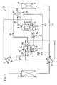
- the present first embodiment is an air conditioner (10) formed by a refrigeration system according to the present invention.
- the air conditioner (10) of the present embodiment is provided with a refrigerant circuit (11).
- the refrigerant circuit (11) is charged with carbon dioxide (CO 2 ) as a refrigerant.
- CO 2 carbon dioxide
- the compressor (20) and the expander (30) are so arranged as to occupy approximately the same level of height.
- a delivery pipe (26) of the compressor (20) is connected to a first port of the first four-way selector valve (12) and an intake pipe (25) of the compressor (20) is connected to a second port of the first four-way selector valve (12).
- An outflow pipe (36) of the expander (30) is connected to a first port of the second four-way selector valve (13) and an inflow pipe (35) of the expander (30) is connected to a second port of the second four-way selector valve (13).
- One end of the outdoor heat exchanger (14) is connected to a third port of the first four-way selector valve (12) and the other end thereof is connected to a fourth port of the second four-way selector valve (13).
- One end of the indoor heat exchanger (15) is connected to a third port of the second four-way selector valve (13) and the other end thereof is connected to a fourth port of the first four-way selector valve (12).
- the intake and delivery pipes (25, 26) of the compressor (20) and the inflow and outflow pipes (35, 36) of the expander (30) will be described later in detail.
- the outdoor heat exchanger (14) is an air heat exchanger for the heat exchange of the refrigerant with the outdoor air.
- the indoor heat exchanger (15) is an air heat exchanger for the heat exchange of the refrigerant with the room air.
- the first and second four-way selector valves (12, 13) are each configured so as to be selectively switchable between a first state (indicated by solid line in Figure 1 ) and a second state (indicated by broken line in Figure 1 ). In the first state, the first and third ports fluidly communicate with each other and, in addition, the second and fourth ports fluidly communicate with each other. On the other hand, in the second state, the first and fourth ports fluidly communicate with each other and, in addition, the second and third ports fluidly communicate with each other.
- the compressor (20) is a so-called "hermetical compressor” of the high pressure dome type.
- the compressor (20) is provided with a compressor casing (24) which is shaped like a vertically elongated cylinder.
- the compression mechanism (21) constitutes a positive displacement fluid machine of the so-called “rotary type”.
- the electric motor (23) overlies the compression mechanism (21).
- the drive shaft (22) vertically extends for connection of the compression mechanism (21) and the electric motor (23).
- Refrigeration oil as a lubricant oil is stored in the bottom of the compressor casing (24).
- an oil sump (27) is formed within the compressor casing (24).
- the drive shaft (22) constitutes an oil supply mechanism for the supply of refrigeration oil to the compression mechanism (21) from the oil sump (27).
- This oil supply passageway is open at the lower end of the drive shaft (22), and constitutes a so-called "centrifugal pump".
- the lower end of the drive shaft (22) is in the state of being dipped into the oil sump (27).
- refrigeration oil is drawn into the oil supply passageway from the oil sump (27) by centrifugal pump action.
- the refrigeration oil drawn into the oil supply passageway is supplied to the compression mechanism (21) where it is used to lubricate the compression mechanism (21).
- the expander (30) is provided with an expander casing (34) which is shaped like a vertically elongated cylinder.
- the expander casing (34) houses therein an expansion mechanism (31), an electric power generator (33), and an output shaft (32).
- the compression mechanism (31) constitutes a positive displacement fluid machine of the so-called "rotary type”.
- the electric power generator (33) underlies the expansion mechanism (31).
- the output shaft (32) vertically extends for connection of the expansion mechanism (31) and the electric power generator (33).
- Refrigeration oil as a lubricant oil is stored in the bottom of the expander casing (34).
- an oil sump (37) is formed within the expander casing (34).
- the output shaft (32) constitutes an oil supply mechanism for the supply of refrigeration oil to the expansion mechanism (31) from the oil sump (37).
- This oil supply passageway is open at the lower end of the output shaft (32), and constitutes a so-called "centrifugal pump".
- the lower end of the output shaft (32) is in the state of being dipped into the oil sump (37).
- refrigeration oil is drawn into the oil supply passageway from the oil sump (37) by centrifugal pump action.
- the refrigeration oil drawn into the oil supply passageway is supplied to the expansion mechanism (31) where it is used to lubricate the expansion mechanism (31).
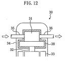
- the aforesaid inflow and outflow pipes (35, 36) are mounted to the expander casing (34). Both the inflow pipe (35) and the outflow pipe (36) pass completely through the expander casing (34) in the vicinity of the upper end of the body thereof.
- the terminal end of the inflow pipe (35) is connected directly to the expansion mechanism (31).
- the start end of the outflow pipe (36) is connected directly to the expansion mechanism (31).
- the expansion mechanism (31) is configured to expand refrigerant admitted thereto by way of the inflow pipe (35) and send the expanded refrigerant directly to outside the expander casing (34) through the outflow pipe (36). In other words, in the expander (30), refrigerant flowing through the inflow pipe (35) will not flow into the internal space of the expander casing (34) but pass through only the expansion mechanism (31).
- the intake pipe (25) and the delivery pipe (26) are mounted to the compressor casing (24).
- the intake pipe (25) passes completely through the compressor casing (24) in the vicinity of the lower end of the body thereof and its terminal end is connected directly to the compression mechanism (21).
- the delivery pipe (26) of the present embodiment is made up of a first high pressure pipe (28) and a second high pressure pipe (29).
- the first high pressure pipe (28) is connected between the compressor casing (24) and the expander casing (34). More specifically, one end of the first high pressure pipe (28) passes completely through the vicinity of the upper end of the body of the compressor casing (24) and the start end thereof is open to a space above the electric motor (23) in the compressor casing (24). The other end of the first high pressure pipe (28) is open to a space between the expansion mechanism (31) and the electric power generator (33) in the internal space of the expander casing (34).
- the second high pressure pipe (29) is connected between the first four-way selector valve (12) and the expander casing (34).
- one end of the second high pressure pipe (29) passes completely through the body of the expander casing (34) and the start end thereof is open to a space between the expansion mechanism (31) and the electric power generator (33) in the expander casing (34).
- the other end of the second high pressure pipe (29) is connected to the first port of the first four-way selector valve (12). That is, the expander casing (34) is connected in the middle of piping on the delivery side of the compressor (20) (i.e., the delivery pipe (26)).
- refrigerant directly drawn into the compression mechanism (21) from the intake pipe (25) is compressed and then delivered into the compressor casing (24). That is to say, the inside of the compressor casing (24) is formed into a high pressure space. And the delivered refrigerant in the compressor casing (24) passes sequentially through the first high pressure pipe (28), then through the inside of the expander casing (34), and then through the second high pressure pipe (29) and flows to the outdoor heat exchanger (14) or to the indoor heat exchanger (15).
- the refrigerant circuit (11) of the present embodiment is configured such that all of the refrigerant delivered out from the compressor (20) flows and passes through the internal space of the expander casing (34) and then flows to the heat exchanger (14, 15) that functions as a heat dissipation unit.
- the inside of the compressor casing (24) and the inside of the expander casing (34) are filled with high pressure refrigerant and their internal pressures are at roughly the same level of pressure.
- the first high pressure pipe (28) and the second high pressure pipe (29) together constitute a refrigerant delivery passageway for the compressor (20) and, in addition, these high pressure pipes together constitute a pressure equalizing passageway for pressure equalizing the inside of the compressor casing (24) and the inside of the expander casing (34) by high pressure.
- the oil distribution pipe (41) constitutes an oil distribution passageway.
- One end of the oil distribution pipe (41) is connected to the lower part of the side surface of the compressor casing (24).
- the one end of the oil distribution pipe (41) is open to the internal space of the compressor casing (24) at a position located higher than the lower end of the drive shaft (22) by a predetermined value.
- the level of oil in the oil sump (27) within the compressor casing (24) stays above the one end of the oil distribution pipe (41).
- the other end of the oil distribution pipe (41) is connected to the lower part of the side surface of the expander casing (34).
- the other end of the oil distribution pipe (41) is open to the internal space of the expander casing (34) at a position located higher than the lower end of the output shaft (32) by a predetermined value. In the normal operation state, the level of oil in the oil sump (37) within the expander casing (34) stays above the other end of the oil distribution pipe (41).
- the oil distribution pipe (41) is provided with an oil regulating valve (52).
- the oil regulating valve (52) is a solenoid valve configured to selectively switch between the opened and closed states in response to a signal provided from the outside.
- the expander casing (34) houses therein an oil level sensor (51).
- the oil level sensor (51) is configured to detect the height of the level of oil in the oil sump (37) within the expander casing (34), and constitutes an oil level detector.
- the air conditioner (10) is provided with a controller (53).
- the controller (53) constitutes a control means for controlling the oil regulating valve (52) in response to a signal outputted from the oil level sensor (51).
- the oil regulating valve (52), the oil level sensor (51), and the controller (53) together constitute a regulating means (50) for regulating the distribution state of refrigeration oil in the oil distribution pipe (41).
- the oil regulating valve (52) constitutes a control valve which is operated in response to the output of the oil level sensor (51).
- the first four-way selector valve (12) and the second four-way selector valve (13) each change state to the state indicated by solid line in Figure 1 , and refrigerant is circulated in the refrigerant circuit (11) to effect a vapor-compression refrigeration cycle.
- the level of high pressure of the refrigeration cycle operated in the refrigerant circuit (11) is set at a higher value than the critical pressure of carbon dioxide as the refrigerant.
- the compression mechanism (21) is rotationally driven by the electric motor (23).
- the compression mechanism (21) compresses refrigerant drawn thereinto through the intake pipe (25) and delivers it into the compressor casing (24).
- the high pressure refrigerant in the compressor casing (24) is discharged out to the first high pressure pipe (28).
- the refrigerant discharged out to the first high pressure pipe (28) flows into the expander casing (34), and is discharged out to the second high pressure pipe (29). That is, the refrigerant delivered out from the compressor (20) passes through the inside of the expander casing (34).
- the internal pressure of the expander casing (34) becomes almost the same as the internal pressure of the compressor casing (24), whereby the inside of the casing (24) and the inside of the casing (34) are pressure equalized each other.
- the refrigerant delivered out to the second high pressure pipe (29) is fed to the outdoor heat exchanger (14) where it dissipates heat to the outdoor air.
- the high pressure refrigerant after heat dissipation in the outdoor heat exchanger (14) flows into the expander (30).
- the high pressure refrigerant admitted to the expansion mechanism (31) by way of the inflow pipe (35) expands by which expansion the electric power generator (33) is rotationally driven. Electric power generated in the electric power generator (33) is supplied to the electric motor (23) of the compressor (20).
- the refrigerant expanded in the expansion mechanism (31) is fed out from the expander (30) by way of the outflow pipe (36).
- the refrigerant fed out from the expander (30) is fed to the indoor heat exchanger (15).
- the indoor heat exchanger (15) the refrigerant admitted thereto absorbs heat from the indoor air and evaporates, whereby the indoor air is cooled.
- the low pressure refrigerant evaporated in the indoor heat exchanger (15) flows to the intake pipe (25) of the compressor (20), and is compressed again in the compression mechanism (21).
- the first four-way selector valve (12) and the second four-way selector valve (13) each change state to the state indicated by broken line in Figure 2 , and refrigerant is circulated in the refrigerant circuit (11) to effect a vapor-compression refrigeration cycle.
- the level of high pressure of the refrigeration cycle operated in the refrigerant circuit (11) is set at a higher value than the critical pressure of carbon dioxide as the refrigerant.
- the compression mechanism (21) is rotationally driven by the electric motor (23).
- the compression mechanism (21) compresses refrigerant drawn thereinto from the intake pipe (25) and delivers it into the compressor casing (24).
- the high pressure refrigerant in the compressor casing (24) is discharged out to the first high pressure pipe (28).
- the refrigerant discharged out to the first high pressure pipe (28) flows into the expander casing (34), and is discharged out to the second high pressure pipe (29). That is, the refrigerant delivered out from the compressor (20) passes through the inside of the expander casing (34).
- the internal pressure of the expander casing (34) becomes almost the same as the internal pressure of the compressor casing (24), whereby the inside of the casing (24) and the inside of the casing (34) are pressure equalized each other.
- the refrigerant discharged out to the second high pressure pipe (29) is fed to the indoor heat exchanger (15).
- the indoor heat exchanger (15) the refrigerant admitted thereto dissipates heat to the indoor air, whereby the indoor air is heated.
- the high pressure refrigerant after heat dissipation in the indoor heat exchanger (15) flows into the expander (30).
- the expander (30) the high pressure refrigerant admitted to the expansion mechanism (31) via the inflow pipe (35) expands by which expansion the electric power generator (33) is rotationally driven. Electric power generated in the electric power generator (33) is supplied to the electric motor (23) of the compressor (20).
- the refrigerant expanded in the expansion mechanism (31) is fed out from the expander (30) by way of the outflow pipe (36).
- the refrigerant fed out from the expander (30) is fed to the outdoor heat exchanger (14).
- the refrigerant admitted thereto absorbs heat from the outdoor air and evaporates.
- the low pressure refrigerant evaporated in the outdoor heat exchanger (14) flows to the intake pipe (25) of the compressor (20), and is compressed again in the compression mechanism (21).
- the supply of refrigeration oil is provided to the compression mechanism (21) from the oil sump (27) within the compressor casing (24).
- the refrigeration oil supplied to the compression mechanism (21) is used to lubricate the compression mechanism (21), but a part of the supplied refrigeration oil is delivered, together with refrigerant after compression, to the internal space of the compressor casing (24).
- the refrigeration oil delivered out from the compression mechanism (21) together with the refrigerant is partially separated from the refrigerant during its passage, for example, through a clearance defined between the rotor and the stator of the electric motor (23) or through a clearance defined between the stator and the compressor casing (24).
- Refrigeration oil separated from the refrigerant in the compressor casing (24) flows down to the oil sump (27).
- refrigeration oil, having been left unseparated from the refrigerant is discharged out to the first high pressure pipe (28).
- the supply of refrigeration oil is provided to the expansion mechanism (31) from the oil sump (37) within the expander casing (34).
- the refrigeration oil supplied to the expansion mechanism (31) is used to lubricate the expansion mechanism (31), but a part of the supplied refrigeration oil is discharged out to outside the expander (30) by way of the outflow pipe (36), together with refrigerant after compression.
- refrigeration oil is discharged out from the compressor (20) and the expander (30).
- the refrigeration oil discharged out from the compressor (20) and the expander (30) circulates in the refrigerant circuit (11) together with refrigerant and then returns again to the compressor (20) and the expander (30).
- refrigeration oil flowing in the refrigerant circuit (11) is drawn by way of the intake pipe (25) into the compression mechanism (21) together with refrigerant.
- the refrigeration oil drawn into the compression mechanism (21) from the intake pipe (25) is delivered into the internal space of the compressor casing (24) together with the refrigerant after compression.
- a part of the refrigeration oil delivered out from the compression mechanism (21) together with refrigerant is separated from the refrigerant during its flowing through the internal space of the compressor casing (24), and then returns to the oil sump (27). That is, during the operation of the compressor (20), refrigeration oil in the compressor casing (24) is discharged out from the delivery pipe (26) while simultaneously refrigeration oil drawn into the compression mechanism (21) from the intake pipe (25) returns to the oil sump (27) within the compressor casing (24).
- refrigeration oil flowing in the refrigerant circuit (11) flows into the expansion mechanism (31) by way of the inflow pipe (35) together with refrigerant.
- refrigerant expanded in the expansion mechanism (31) is fed out directly to outside the expander casing (34) by way of the outflow pipe (36), which means that refrigeration oil is fed out to outside the expander casing (34) as it is. That is, in the expander (30), refrigeration oil flowing in the refrigerant circuit (11) flows into the expansion mechanism (31), but it does not return to the oil sump (37) within the expander casing (34) but is fed out, as it is, from the expander (30). Therefore, in this state, the amount of storage of refrigeration oil in the expander casing (34) will decrease gradually.
- refrigeration oil discharged out to the first high pressure pipe (28) from within the compressor casing (24) together with refrigerant, first flows into the expander casing (34).
- the refrigeration oil admitted to the expander casing (34) is separated from the refrigerant during its passage through the vicinity of the expansion mechanism (31) and through the vicinity of the electric power generator (33) and flows down towards the oil sump (37).
- the refrigerant, after having been separated from the refrigeration oil, is discharged out from the second high pressure pipe (29). That is, in the expander (30), refrigeration oil is brought back to the oil sump (37) within the expander casing (34) from the first high pressure pipe (28) at the same time that refrigeration oil is discharged out from the outflow pipe (36).
- the controller (53) decides based on the output signal of the oil level sensor (51) that the height of the level of oil in the oil sump (37) within the expander casing (34) falls below a predetermined lower limit value, the controller (53) provides control so that the oil regulating valve (52) is opened.
- the oil sump (27) within the compressor casing (24) and the oil sump (37) within the expander casing (34) become fluidly communicative with each other.
- the height of the level of oil in the oil sump (37) within the expander casing (34) is being lower than the height of the level of oil in the oil sump (27) within the compressor casing (24).
- refrigeration oil flows from the oil sump (27) within the compressor casing (24) to the oil sump (37) within the expander casing (34) by way of the oil distribution pipe (41) because the compressor casing (24) and the expander casing (34) are approximately equal to each other in internal pressure.
- the controller (53) decides based on the output signal of the oil level sensor (51) that the position of the level of oil in the oil sump (37) rises up to a predetermined reference value, then the controller (53) provides control so that the oil regulating valve (52) is closed. This ensures the amount of storage of refrigeration oil in each of the compressor (20) and the expander (30).
- the controller (53) decides based on the output signal of the oil level sensor (51) that the height of the level of oil in the oil sump (37) within the expander casing (34) exceeds a predetermined upper limit value, then the controller (53) provides control so that the oil regulating valve (52) is opened.
- the controller (53) decides based on the output signal of the oil level sensor (51) that the position of the level of oil in the oil sump (37) falls down to a predetermined reference value, then the controller (53) provides control so that the oil regulating valve (52) is closed. This ensures the amount of storage of refrigeration oil in each of the compressor (20) and the expander (30).
- the controller (53) provides control of the oil regulating valve (52) so that the supply of refrigeration oil is provided from one oil sump (27, 37) in excess supply of refrigeration oil to the other one (27, 37) in short supply of refrigeration oil.
- the expander casing (34) is connected in the middle of the delivery pipe (26) of the compressor (20) and, in addition, the oil distribution pipe (41) is provided for fluid communication between the oil sump (27) of the compressor casing (24) and the oil sump (37) of the expander casing (34).
- the oil distribution pipe (41) is provided for fluid communication between the oil sump (27) of the compressor casing (24) and the oil sump (37) of the expander casing (34).
- refrigeration oil delivered out from the compressor (20) together with refrigerant is collected in the expander casing (34). That is, the refrigerant circuit (11) of the present embodiment is configured such that the expander (30) serves also as an oil separator.
- the refrigerant discharged out to the second high pressure pipe (29) from the expander casing (34) flows to the outdoor heat exchanger (14) in the cooling mode operation while in the heating mode operation it flows to the indoor heat exchanger (15). Therefore, it is possible to reduce the amount of refrigeration oil flowing into either the outdoor heat exchanger (14) or the indoor heat exchanger (15), whichever functions as a gas cooler.
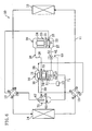
- the air conditioner (10) of the present second embodiment has a refrigerant circuit (11) similar to the refrigerant circuit (11) of the first embodiment but additionally including an oil separator (60) and an oil return pipe (61).
- an oil separator 60
- an oil return pipe 61
- the oil separator (60) is disposed on the delivery side of the compressor (20), i.e., in the middle of the first high pressure pipe (28). That is, the oil separator (60) is disposed upstream of the expander casing (34) in piping on the delivery side of the compressor (20).
- the oil separator (60) is for the separation of refrigeration oil from refrigerant drawn into the compressor (20). More specifically, the oil separator (60) has a main body member (65) which is shaped like a vertically elongated cylindrical, hermetic container. This main body member (65) is provided with an inlet pipe (66) and an outlet pipe (67).
- the inlet pipe (66) projects laterally from the main body member (65) and passes completely through the upper portion of the side wall part of the main body member (65).
- the outlet pipe (67) projects upwardly from the main body member (65) and passes completely through the top part of the main body member (65).
- the inlet pipe (66) of the oil separator (60) is connected to the first high pressure pipe (28) which extends from the compressor casing (24).
- the outlet pipe (67) of the oil separator (60) is connected to the first high pressure pipe (28) which extends from the expander casing (34).
- the oil return pipe (61) is connected between the oil separator (60) and the expander casing (34). One end of the oil return pipe (61) is connected to the bottom part of the main body member (65) of the oil separator (60). The other end of the oil return pipe (61) is connected to the bottom part of the expander casing (34). That is, the internal space of the main body member (65) of the oil separator (60) fluidly communicates through the oil return pipe (61) with the oil sump (37) within the expander casing (34).
- the oil return pipe (61) constitutes an oil return passageway for directing refrigeration oil to the oil sump (37) within the expander casing (34) from the main body member (65) of the oil separator (60).
- the operation of the air conditioner (10) of the present embodiment in the cooling and heating mode operations is the same as the operation of the air conditioner (10) of the first embodiment in the cooling and heating mode operations.
- the operation of control of the level of oil which is performed in the air conditioner (10) of the present embodiment will be described below.
- Refrigeration oil delivered out from the compressor casing (24) to the first high pressure pipe (28) together with refrigerant, flows into the main body member (65) of the oil separator (60), and is separated from the refrigerant and accumulated in the bottom.
- the refrigerant after the separation from the refrigeration oil in the oil separator (60) is discharged out to the first high pressure pipe (28) via the outlet pipe (67) and then flows into the expander casing (34).
- it is not necessarily the case that all of the refrigeration oil will be separated from the refrigerant in the oil separator (60). Therefore, if there is some refrigeration oil that has been left unseparated from refrigerant, such refrigeration oil flows into the expander casing (34) together with the refrigerant where it is separated from the refrigerant and then stored in the oil sump (37).
- Refrigeration oil collected in the main body member (65) of the oil separator (60) is supplied by way of the oil return pipe (61) to the oil sump (37) within the expander casing (34).
- the oil return pipe (61) to the oil sump (37) within the expander casing (34).
- all or most of the refrigeration oil discharged out from the compressor (20) is returned through the oil separator (60) into the expander casing (34), and refrigeration oil, having been left unseparated from refrigerant in the oil separator (60), is retuned directly into the expander casing (34).
- refrigerant delivered out from the compressor (20) passes via the oil separator (60) through the inside of the expander casing (34), whereby the compressor casing (24) and the expander casing (34) are equalized in their internal pressure.
- refrigeration oil discharged out from the expansion mechanism (31) of the expander (30) together with refrigerant flows in the refrigerant circuit (11), and is drawn into the compression mechanism (21) of the compressor (20).
- the refrigeration oil drawn into the compression mechanism (21) is delivered out to the internal space of the compressor casing (24) together with refrigerant after compression and a part thereof is stored in the oil sump (27) within the compressor casing (24).
- the controller (53) controls the oil regulating valve (52). That is, if the controller (53) decides that the height of the level of oil in the oil sump (37) within the expander casing (34) exceeds a predetermined upper limit value, then the controller (53) provides control so that the oil regulating valve (52) is opened. Thereafter, if the controller (53) decides that the height of the level of oil in the oil sump (37) within the expander casing (34) falls down to a predetermine reference value, then the controller (53) provides control so that the oil regulating valve (52) is closed.
- the controller (53) decides that the height of the level of oil in the oil sump (37) within the expander casing (34) falls below a predetermined lower limit value, then the controller (53) provides control so that the oil regulating valve (52) is opened. Thereafter, if the controller (53) decides that the height of the level of oil in the oil sump (37) within the expander casing (34) rises up to a predetermine reference value, then the controller (53) provides control so that the oil regulating valve (52) is closed. In the way as described above, the controller (53) provides control of the oil regulating valve (52) whereby the amount of storage of refrigeration oil is ensured in each of the compressor (20) and the expander (30).
- the oil separator (60) is arranged in the first high pressure pipe (28) on the delivery side of the compressor (20), thereby making it possible to ensure that refrigeration oil discharged out from the compressor (20) is collected without fail by the oil separator (60) and the expander casing (34). This therefore ensures that the amount of refrigeration oil flowing into either the outdoor heat exchanger (14) or the indoor heat exchanger (15), whichever functions as a gas cooler, can be reduced without fail. As a result, it becomes possible to ensure that it is prevented without fail that the exchange of heat between refrigerant and air in the heat exchanger (14, 15) functioning as a gas cooler is inhibited due to refrigeration oil, thereby enabling the heat exchanger (14, 15) to operate with satisfactory performance.
- the present modification includes a refrigerant circuit (11) similar to the refrigerant circuit (11) of the second embodiment, with the exception that the oil separator (60) is connected not to the expander casing (34) but to the compressor casing (24).
- the main body member (65) of the oil separator (60) and the compressor casing (24) are connected together by an oil return pipe (62).
- One end of the oil return pipe (62) is connected to the bottom part of the main body member (65) of the oil separator (60) and the other end thereof is connected to the bottom part of the compressor casing (24). That is, the internal space of the main body member (65) of the oil separator (60) fluidly communicates through the oil return pipe (62) with the oil sump (27) within the compressor casing (24).
- the oil return pipe (62) constitutes an oil return passageway for directing refrigeration oil to the oil sump (37) within the compressor casing (24) from the main body member (65) of the oil separator (60).
- refrigeration oil discharged out from the compressor (20) together with refrigerant flows into the main body member (65) of the oil separator (60), and is separated from the refrigerant and accumulated in the bottom.
- the refrigeration oil accumulated in the main body member (65) is supplied by way of the oil return pipe (62) to the oil sump (27) within the compressor casing (24).
- Refrigeration oil, having been left unseparated in the oil separator (60) is brought back into the expander casing (34). That is, in the present modification, all or most of the refrigeration oil discharged out from the compressor (20) is retuned to the compressor (20).
- the controller (53) decides that the height of the level of oil in the oil sump (37) within the expander casing (34) falls below a predetermined lower limit value, then the controller (53) provides control so that the oil regulating valve (52) is opened. Thereafter, if the controller (53) decides that the height of the level of oil in the oil sump (37) within the expander casing (34) rises up to a predetermined reference value, then the controller (53) provides control so that the oil regulating valve (52) is closed. As a result, excess refrigeration oil is supplied to the expander (30) from the compressor (20). In this way as described above, the controller (53) provides control of the oil regulating valve (52) whereby refrigeration oil temporarily collected in the oil sump (27) within the compressor casing (24) is distributed to the oil sump (37) within the expander casing (34).
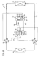
- the air conditioner (10) of the present third embodiment is provided with a refrigerant circuit (11) similar to the counterpart of the first embodiment but additionally including an oil separator (70) and an oil return pipe (71).
- a refrigerant circuit (11) similar to the counterpart of the first embodiment but additionally including an oil separator (70) and an oil return pipe (71).
- the oil separator (70) is disposed in the middle of the second high pressure pipe (29). That is, the oil separator (70) is provided downstream of the expander casing (34) in piping on the delivery side of the compressor (20).
- the oil separator (70) itself is configured in the same way that the oil separator (60) of the second embodiment is configured. That is, the oil separator (70) is provided with a main body member (65), an inlet pipe (66), and an outlet pipe (67).
- the inlet pipe (66) of the oil separator (70) is connected to the second high pressure pipe (29) which extends from the expander casing (34).
- the outlet pipe (67) of the oil separator (70) is connected to the second high pressure pipe (29) which extends from the first four-way selector valve (12).
- the oil return pipe (71) is connected between the oil separator (70) and the expander casing (34). One end of the oil return pipe (71) is connected to the bottom part of the main body member (65) of the oil separator (70). The other end of the oil return pipe (71) is connected to the bottom part of the expander casing (34). That is, the oil return pipe (71) constitutes an oil return passageway for directing refrigeration oil to the oil sump (37) within the expander casing (34) from the main body member (65) of the oil separator (70), as in the case of the second embodiment.
- the operation of the air conditioner (10) of the present embodiment in the cooling and heating mode operations is the same as the operation of the air conditioner (10) of the first embodiment in the cooling and heating mode operations.
- the operation of control of the level of oil which is performed in the air conditioner (10) of the present embodiment will be described below.
- Refrigeration oil discharged out from the compressor casing (24) to the first high pressure pipe (28) together with refrigerant, flows into the expander casing (34) wherein the refrigeration oil is separated from the refrigerant and then stored in the oil sump (37).
- the refrigerant after the separation from the refrigeration oil in the expander casing (34) flows through the second high pressure pipe (29) into the main body member (65) of the oil separator (70).
- the present embodiment ensures that refrigeration oil discharged out from the compressor (20) is brought back into the expander casing (34) without fail.
- refrigerant delivered out from the compressor (20) passes through the inside of the expander casing (34) whereby the compressor casing (24) and the expander casing (34) are equalized in their internal pressure.
- refrigeration oil discharged out from the expansion mechanism (31) of the expander (30) together with refrigerant, flows in the refrigerant circuit (11) , and is drawn into the compression mechanism (21) of the compressor (20).
- the refrigeration oil drawn into the compression mechanism (21) is delivered to the internal space of the compressor casing (24) together with the refrigerant after compression and a part thereof is stored in the oil sump (27) within the compressor casing (24).
- the controller (53) decides that the height of the level of oil in the oil sump (37) within the expander casing (34) exceeds a predetermined upper limit value, then the controller (53) provides control so that the oil regulating valve (52) is opened. Thereafter, if the controller (53) decides that the height of the level of oil in the oil sump (37) within the expander casing (34) falls down to a predetermined reference value, then the controller (53) provides control so that the oil regulating valve (52) is closed. On the other hand, if the controller (53) decides that the height of the level of oil in the oil sump (37) within the expander casing (34) falls below a predetermined lower limit value, then the controller (53) provides control so that the oil regulating valve (52) is opened.
- controller (53) decides that the height of the level of oil in the oil sump (37) within the expander casing (34) rises up to a predetermine reference value, then the controller (53) provides control so that the oil regulating valve (52) is closed.
- the oil separator (70) is arranged in the second high pressure pipe (29) on the delivery side of the compressor (20), thereby making it possible to ensure that refrigeration oil discharged out from the compressor (20) is collected without fail by the expander casing (34) and the oil separator (70). This therefore ensures that the amount of refrigeration oil flowing into either the outdoor heat exchanger (14) or the indoor heat exchanger (15), whichever functions as a gas cooler, can be reduced without fail. As a result, it becomes possible to ensure that it is prevented without fail that the exchange of heat between refrigerant and air in the heat exchanger (14, 15) functioning as a gas cooler is inhibited due to refrigeration oil, thereby enabling the heat exchanger (14, 15) to operate with satisfactory performance.
- the present modification includes a refrigerant circuit (11) similar to the refrigerant circuit (11) of the third embodiment, with the exception that the oil separator (70) is connected not to the expander casing (34) but to the compressor casing (24).
- the main body member (65) of the oil separator (70) and the compressor casing (24) are connected together by an oil return pip (72).
- One end of the oil return pipe (72) is connected to the bottom part of the main body member (65) of the oil separator (70) and the other end thereof is connected to the bottom part of the compressor casing (24).
- the oil return pipe (72) constitutes an oil return passageway for establishing fluid communication between the main body member (65) of the oil separator (70) and the oil sump (27) within the compressor casing (24).
- refrigeration oil delivered out from the compressor (20) together with refrigerant, flows into the expander casing (34) where the refrigeration oil is separated from the refrigerant and then stored in the oil sump (37).
- Refrigeration oil having been left unseparated from refrigerant in the expander casing (34) flows into the main body member (65) of the oil separator (70) where the refrigeration oil is separated from the refrigerant and then accumulated in the bottom.
- the refrigeration oil accumulated in the main body member (65) is supplied by way of the oil return pipe (72) to the oil sump (27) within the compressor casing (24). That is, in the present modification, most of the refrigeration oil discharged out from the compressor (20) is brought back to the expander (30), but a part thereof is brought back to the compressor (20).
- the controller (53) provides control of the oil regulating valve (52), as in the case of the third embodiment.
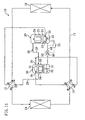
- the air conditioner (10) of the present fourth embodiment is provided with a refrigerant circuit (11) similar to the counterpart of the first embodiment but additionally including an oil separator (75) and an oil return pipe (76).
- a refrigerant circuit (11) similar to the counterpart of the first embodiment but additionally including an oil separator (75) and an oil return pipe (76).
- the oil separator (75) is arranged on the outflow side of the expander (30).
- the oil separator (75) itself is configured in the same way that the oil separator (60) of the second embodiment is configured. That is, the oil separator (75) is provided with a main body member (65), an inlet pipe (66), and an outlet pipe (67).
- the inlet pipe of (66) of the oil separator (75) is connected to the outflow pipe (36) of the expander (30) and the outlet pipe (67) thereof is connected to the first port of the second four-way selector valve (13).
- oil return pipe (76) One end of the oil return pipe (76) is connected to the bottom part of the main body member (65) of the oil separator (75). The other end of the oil return pipe (76) is connected in the middle of the intake pipe (25) of the compressor (20). That is, the oil return pipe (76) constitutes an oil return passageway for providing the supply of refrigeration oil from the main body member (65) of the oil separator (75) to piping on the intake side of the compressor (20).
- the operation of the air conditioner (10) of the present embodiment in the cooling and heating mode operations is the same as the operation of the air conditioner (10) of the first embodiment in the cooling and heating mode operations.
- the operation of control of the level of oil which is performed in the air conditioner (10) of the present embodiment will be described below.
- Refrigeration oil delivered out from the compressor casing (24) to the first high pressure pipe (28) together with refrigerant, flows into the expander casing (34) wherein the refrigeration oil is separated from the refrigerant and then stored in the oil sump (37).
- the refrigerant after the separation from the refrigeration oil is discharged out from the second high pressure pipe (29), flows through the refrigerant circuit (11), and flows through the inflow pipe (35) into the expansion mechanism (31).
- the refrigeration oil admitted to the expansion mechanism (31) is discharged out from the expander (30) by way of the outflow pipe (36), together with the refrigeration oil supplied from the oil sump (37) within the expander casing (34) to the expansion mechanism (31).
- the refrigeration oil discharged out from the expander (30) flows into the main body member (65) of the oil separator (75).
- the main body member (65) of the oil separator (75) In the inside of the main body member (65), a mixture of liquid refrigerant and refrigeration oil is accumulated in the lower part and gas refrigerant is accumulated in the upper part.
- the specific gravity of refrigeration oil is larger than the specific gravity of liquid refrigerant. Therefore, the deeper in the liquid sump within the main body member (65), the higher the percentage of refrigeration oil, and the shallower in the liquid sump within the main body member (65), the higher the percentage of liquid refrigerant.
- the outlet pipe (67) of the oil separator (75) is in the state in which its lower end is dipped into the liquid sump within the main body member (65). Liquid refrigerant present in the upper layer of the liquid sump is discharged out from the main body member (65) by way of the outlet pipe (67) and selectively flows to the indoor heat exchanger (15) in the cooling mode operation or to the outdoor heat exchanger (14) in the heating mode operation.
- the refrigeration oil drawn into the compression mechanism (21) is delivered out to the internal space of compressor casing (24) together with the refrigerant after compression, and a part thereof is stored in the oil sump (27) within the compressor casing (24). That is, also in the present embodiment, refrigeration oil discharged out from the compressor (20) and refrigeration oil discharged out from the expander (30) are returned into the compressor casing (24) and into the expander casing (34).
- refrigerant delivered out from the compressor (20) passes through the inside of the expander casing (34) whereby the compressor casing (24) and the expander casing (34) are equalized in their internal pressure.
- the controller (53) controls the oil regulating valve (52). That is, if the controller (53) decides that the height of the level of oil in the oil sump (37) within the expander casing (34) exceeds a predetermined upper limit value, then the controller (53) provides control so that the oil regulating valve (52) is opened. Thereafter, if the controller (53) decides that the height of the level of oil in the oil sump (37) within the expander casing (34) falls down to a predetermine reference value, then the controller (53) provides control so that the oil regulating valve (52) is closed.
- the controller (53) decides that the height of the level of oil in the oil sump (37) within the expander casing (34) falls below a predetermined lower limit value, then the controller (53) provides control so that the oil regulating valve (52) is opened. Thereafter, if the controller (53) decides that the height of the level of oil in the oil sump (37) within the expander casing (34) rises up to a predetermine reference value, then the controller (53) provides control so that the oil regulating valve (52) is closed.
- the collecting of lubricant oil is carried out by the oil separator (75) arranged on the outflow side of the expander (30).
- refrigerant forced out from the expander (30) and immediately after the passage through the oil separator (75) selectively flows to the indoor heat exchanger (15) in the cooling mode operation or to the outdoor heat exchanger (14) in the heating mode operation. Therefore, it is possible to reduce the amount of refrigeration oil flowing into either the outdoor heat exchanger (14) or the indoor heat exchanger (15), whichever functions as an evaporator.
- a capillary tube (54) as a regulating means may be disposed in the middle of the oil distribution pipe (41), as shown in Figure 9.
- Figure 9 shows a refrigerant circuit (11) resulting from applying the present modification to the first embodiment.
- the flow velocity of refrigeration oil flowing through the oil distribution pipe (41) is controlled to below a certain level. Consequently, even in the condition in which the internal pressure of the compressor casing (24) and the internal pressure of the expander casing (34) transiently differ from each other, it is possible to prevent the flow of refrigeration oil from one of the compressor (20) and the expander (30) to the other one by way of the oil distribution pipe (41). This makes it possible to ensure the amount of storage of refrigeration oil in each of the compressor (20) and the expander (30).
- the regulating means may be omitted, as shown in Figure 10.
- Figure 10 shows a refrigerant circuit (11) resulting from applying the present modification to the first embodiment.
- the oil sump (27) within the compressor casing (24) and the oil sump (37) of the expander casing (34) are placed in the state in which they are constantly fluidly communicated with each other by the oil distribution pipe (41).
- the oil distribution pipe (41) refrigeration oil flows and passes from either one of the oil sump (27) within the compressor casing (24) and the oil sump (37) within the expander casing (34), whichever has a higher oil level position, to the other one.
- the flow of refrigeration oil in the oil distribution pipe (41) stops.
- the compressor casing (24) and the expander casing (34) are equalized in the amount of storage of refrigeration oil. Therefore, in accordance with the present modification, it is possible to ensure the reliability of the compressor (20) and the reliability of the expander (30) while preventing the refrigerant circuit (11) from getting complex to the minimum.
- the oil level sensor (51) may be provided not in the expander casing (34) but in the compressor casing (24), as shown in Figure 11.
- Figure 11 shows a refrigerant circuit (11) resulting from applying the present modification to the first embodiment.
- the controller (53) of the present modification decides that the height of the level of oil in the oil sump (27) within the compressor casing (24) falls below a predetermined lower limit value, then the controller (53) provides control so that the oil regulating valve (52) is opened.
- the height of the level of oil in the oil sump (27) within the compressor casing (24) is being lower than the height of the level of oil in the oil sump (37) within the expander casing (34).
- the refrigeration oil in the expander casing (34) flows by way of the oil distribution pipe (41) into the compressor casing (24).
- the controller (53) decides that the position of the level of oil in the oil sump (27) within the compressor casing (24) rises up to a predetermined reference value, then the controller (53) provides control so that the oil regulating valve (52) is closed.
- the controller (53) decides that the height of the level of oil in the oil sump (27) within the compressor casing (24) exceeds a predetermined upper limit value, then the controller (53) provides control so that the oil regulating valve (52) is opened.
- the height of the level of oil in the oil sump (27) within the compressor casing (24) is being higher than the height of the level of oil in the oil sump (37) within the expander casing (34).
- the refrigeration oil in the compressor casing (24) flows by way of the oil distribution pipe (41) into the expander casing (34).
- the controller (53) decides that the position of the level of oil in the oil sump (27) within the compressor casing (24) falls down to a predetermined reference value, then the controller (53) provides control so that the oil regulating valve (52) is closed.
- the expansion mechanism (31) in the expander casing (34) may be enclosed by a heat insulating material (38), as shown in Figure 12 .
- the first high pressure pipe (28) and the second high pressure pipe (29) are omitted in Figure 12 .
- the compressor (20) is of the high pressure dome type, and the atmosphere temperature in the expander casing (34) through which refrigerant delivered out from the compressor (20) is passed becomes higher.
- This allows heat to transfer from the outside to the refrigerant passing through the expansion mechanism (31) of the expander (30), as a result of which the amount of refrigerant heat absorption in the heat exchanger functioning as an evaporator will be reduced by the amount of heat transferred.
- the expansion mechanism (31) is enclosed by the heat insulating material (38), as in the case of the present modification, the amount of heat transferring to the refrigerant passing through the expansion mechanism (31) can be reduced. This makes it possible to reduce the enthalpy of the refrigerant after expansion, thereby enabling the heat exchanger functioning as an evaporator to operate with satisfactory performance.
- the compression mechanism (21) and the expansion mechanism (31) are each implemented by a respective fluid machine of the rotary type.
- the type of fluid machinery that constitutes the compression mechanism (21) and the expansion mechanism (31) is not limited to the rotary type.
- the compression mechanism (21) and the expansion mechanism (31) each may be implemented by a respective fluid machine of the scroll type.
- the compression mechanism (21) and the expander mechanism (31) may be implemented by fluid machines of different types.
- the oil supply passageway formed in the drive shaft (22) of the compressor (20) and the oil supply passageway formed in the output shaft (32) of the expander (30) constitute centrifugal pumps.
- mechanical pumps for example, pumps of the gear type and pumps of the trochoidal type
- these mechanical pumps are driven by the drive shaft (22) and the output shaft (32) for the supply of lubricant oil to the compression mechanism (21) and to the expansion mechanism (31).
- the present invention finds utility in the field of refrigeration systems having a refrigerant circuit including a compressor and an expander which are provided with respective casings.
Landscapes
- Engineering & Computer Science (AREA)
- Physics & Mathematics (AREA)
- Mechanical Engineering (AREA)
- Thermal Sciences (AREA)
- General Engineering & Computer Science (AREA)
- Chemical & Material Sciences (AREA)
- Analytical Chemistry (AREA)
- Power Engineering (AREA)
- Applications Or Details Of Rotary Compressors (AREA)
- Compressor (AREA)
Applications Claiming Priority (2)
| Application Number | Priority Date | Filing Date | Title |
|---|---|---|---|
| JP2006116643A JP4967435B2 (ja) | 2006-04-20 | 2006-04-20 | 冷凍装置 |
| PCT/JP2007/058281 WO2007123085A1 (ja) | 2006-04-20 | 2007-04-16 | 冷凍装置 |
Publications (3)
| Publication Number | Publication Date |
|---|---|
| EP2012075A1 EP2012075A1 (en) | 2009-01-07 |
| EP2012075A4 EP2012075A4 (en) | 2013-05-01 |
| EP2012075B1 true EP2012075B1 (en) | 2014-11-26 |
Family
ID=38624985
Family Applications (1)
| Application Number | Title | Priority Date | Filing Date |
|---|---|---|---|
| EP07741717.8A Active EP2012075B1 (en) | 2006-04-20 | 2007-04-16 | Refrigeration device |
Country Status (7)
| Country | Link |
|---|---|
| US (1) | US7918096B2 (ja) |
| EP (1) | EP2012075B1 (ja) |
| JP (1) | JP4967435B2 (ja) |
| KR (1) | KR100990782B1 (ja) |
| CN (1) | CN101427084B (ja) |
| AU (1) | AU2007241898B2 (ja) |
| WO (1) | WO2007123085A1 (ja) |
Families Citing this family (12)
| Publication number | Priority date | Publication date | Assignee | Title |
|---|---|---|---|---|
| JP4816220B2 (ja) * | 2006-04-20 | 2011-11-16 | ダイキン工業株式会社 | 冷凍装置 |
| JP5169295B2 (ja) * | 2007-03-27 | 2013-03-27 | ダイキン工業株式会社 | 冷凍装置 |
| US9146046B2 (en) | 2010-07-28 | 2015-09-29 | Lg Electronics Inc. | Refrigerator and driving method thereof |
| CN105008824B (zh) * | 2013-02-26 | 2017-10-24 | 艾默生环境优化技术有限公司 | 包括高压侧压缩机和低压侧压缩机的系统 |
| WO2015104822A1 (ja) * | 2014-01-09 | 2015-07-16 | 三菱電機株式会社 | 冷凍サイクル装置 |
| JP6138364B2 (ja) * | 2014-05-30 | 2017-05-31 | 三菱電機株式会社 | 空気調和機 |
| US10801522B2 (en) * | 2014-05-30 | 2020-10-13 | Nuovo Pignone Srl | System and method for draining a wet-gas compressor |
| JP6248878B2 (ja) * | 2014-09-18 | 2017-12-20 | 株式会社富士通ゼネラル | 空気調和装置 |
| WO2020011192A1 (zh) * | 2018-07-12 | 2020-01-16 | 艾默生环境优化技术(苏州)有限公司 | 膨胀机以及包括膨胀机的流体循环系统 |
| KR20200133100A (ko) | 2019-05-17 | 2020-11-26 | 엘지전자 주식회사 | 전동식 팽창기 및 이를 포함하는 공기 조화 시스템 |
| JP6970363B1 (ja) * | 2020-09-30 | 2021-11-24 | ダイキン工業株式会社 | 圧縮装置 |
| CN113203974A (zh) * | 2021-04-25 | 2021-08-03 | 国家电网有限公司 | 电流互感器的油位测量方法 |
Family Cites Families (12)
| Publication number | Priority date | Publication date | Assignee | Title |
|---|---|---|---|---|
| JPH04116348A (ja) * | 1990-09-05 | 1992-04-16 | Naoji Isshiki | 近似逆エリクソンサイクル冷凍機 |
| JP2000241033A (ja) * | 1999-02-23 | 2000-09-08 | Aisin Seiki Co Ltd | 蒸気圧縮式冷凍装置 |
| JP3998249B2 (ja) * | 2003-04-28 | 2007-10-24 | 株式会社日立製作所 | 冷凍サイクル |
| JP4055902B2 (ja) * | 2003-04-28 | 2008-03-05 | 株式会社日立製作所 | 膨張機を備えた冷凍装置 |
| JP2005002832A (ja) * | 2003-06-10 | 2005-01-06 | Daikin Ind Ltd | ロータリー流体機械 |
| JP4561326B2 (ja) * | 2004-03-17 | 2010-10-13 | ダイキン工業株式会社 | 流体機械 |
| JP4516127B2 (ja) * | 2005-08-26 | 2010-08-04 | 三菱電機株式会社 | 冷凍空調装置 |
| JP2007187332A (ja) * | 2006-01-11 | 2007-07-26 | Matsushita Electric Ind Co Ltd | 冷凍サイクル装置 |
| JP2007327696A (ja) * | 2006-06-08 | 2007-12-20 | Daikin Ind Ltd | 冷凍装置 |
| JP2008107049A (ja) * | 2006-10-27 | 2008-05-08 | Matsushita Electric Ind Co Ltd | 冷凍サイクル装置 |
| JP5103952B2 (ja) * | 2007-03-08 | 2012-12-19 | ダイキン工業株式会社 | 冷凍装置 |
| CN101779039B (zh) * | 2008-05-23 | 2013-01-16 | 松下电器产业株式会社 | 流体机械及制冷循环装置 |
-
2006
- 2006-04-20 JP JP2006116643A patent/JP4967435B2/ja active Active
-
2007
- 2007-04-16 EP EP07741717.8A patent/EP2012075B1/en active Active
- 2007-04-16 US US12/226,435 patent/US7918096B2/en active Active
- 2007-04-16 KR KR1020087028191A patent/KR100990782B1/ko not_active IP Right Cessation
- 2007-04-16 WO PCT/JP2007/058281 patent/WO2007123085A1/ja active Application Filing
- 2007-04-16 CN CN2007800139065A patent/CN101427084B/zh active Active
- 2007-04-16 AU AU2007241898A patent/AU2007241898B2/en not_active Ceased
Also Published As
| Publication number | Publication date |
|---|---|
| JP4967435B2 (ja) | 2012-07-04 |
| CN101427084B (zh) | 2010-11-10 |
| AU2007241898A1 (en) | 2007-11-01 |
| WO2007123085A1 (ja) | 2007-11-01 |
| EP2012075A4 (en) | 2013-05-01 |
| KR20080111146A (ko) | 2008-12-22 |
| US20090165480A1 (en) | 2009-07-02 |
| KR100990782B1 (ko) | 2010-10-29 |
| US7918096B2 (en) | 2011-04-05 |
| JP2007285675A (ja) | 2007-11-01 |
| CN101427084A (zh) | 2009-05-06 |
| EP2012075A1 (en) | 2009-01-07 |
| AU2007241898B2 (en) | 2010-05-27 |
Similar Documents
| Publication | Publication Date | Title |
|---|---|---|
| EP2012075B1 (en) | Refrigeration device | |
| EP2009368B1 (en) | Refrigerating apparatus | |
| EP2015003B1 (en) | Refrigerating apparatus | |
| US10378539B2 (en) | System including high-side and low-side compressors | |
| US20080078191A1 (en) | Rotary compressor and heat pump system | |
| JP2007285681A5 (ja) | ||
| JP4591402B2 (ja) | 冷凍装置 | |
| EP3910263B1 (en) | Refrigeration cycle device | |
| JP4720594B2 (ja) | 冷凍装置 | |
| JP4720593B2 (ja) | 冷凍装置 | |
| JP2013087975A (ja) | 冷凍装置 | |
| JPH07259736A (ja) | 冷凍空調装置 |
Legal Events
| Date | Code | Title | Description |
|---|---|---|---|
| PUAI | Public reference made under article 153(3) epc to a published international application that has entered the european phase |
Free format text: ORIGINAL CODE: 0009012 |
|
| 17P | Request for examination filed |
Effective date: 20081105 |
|
| AK | Designated contracting states |
Kind code of ref document: A1 Designated state(s): AT BE BG CH CY CZ DE DK EE ES FI FR GB GR HU IE IS IT LI LT LU LV MC MT NL PL PT RO SE SI SK TR |
|
| AX | Request for extension of the european patent |
Extension state: AL BA HR MK RS |
|
| DAX | Request for extension of the european patent (deleted) | ||
| A4 | Supplementary search report drawn up and despatched |
Effective date: 20130403 |
|
| RIC1 | Information provided on ipc code assigned before grant |
Ipc: F25B 1/00 20060101AFI20130326BHEP Ipc: F25B 43/02 20060101ALI20130326BHEP |
|
| REG | Reference to a national code |
Ref country code: DE Ref legal event code: R079 Ref document number: 602007039427 Country of ref document: DE Free format text: PREVIOUS MAIN CLASS: F25B0001000000 Ipc: F25B0001040000 |
|
| GRAP | Despatch of communication of intention to grant a patent |
Free format text: ORIGINAL CODE: EPIDOSNIGR1 |
|
| RIC1 | Information provided on ipc code assigned before grant |
Ipc: F25B 9/00 20060101ALI20131204BHEP Ipc: F25B 31/00 20060101ALI20131204BHEP Ipc: F25B 1/04 20060101AFI20131204BHEP Ipc: F25B 13/00 20060101ALI20131204BHEP Ipc: F25B 9/06 20060101ALI20131204BHEP |
|
| INTG | Intention to grant announced |
Effective date: 20140107 |
|
| GRAP | Despatch of communication of intention to grant a patent |
Free format text: ORIGINAL CODE: EPIDOSNIGR1 |
|
| INTG | Intention to grant announced |
Effective date: 20140613 |
|
| GRAS | Grant fee paid |
Free format text: ORIGINAL CODE: EPIDOSNIGR3 |
|
| GRAA | (expected) grant |
Free format text: ORIGINAL CODE: 0009210 |
|
| AK | Designated contracting states |
Kind code of ref document: B1 Designated state(s): AT BE BG CH CY CZ DE DK EE ES FI FR GB GR HU IE IS IT LI LT LU LV MC MT NL PL PT RO SE SI SK TR |
|
| REG | Reference to a national code |
Ref country code: GB Ref legal event code: FG4D |
|
| REG | Reference to a national code |
Ref country code: CH Ref legal event code: EP |
|
| REG | Reference to a national code |
Ref country code: AT Ref legal event code: REF Ref document number: 698430 Country of ref document: AT Kind code of ref document: T Effective date: 20141215 |
|
| REG | Reference to a national code |
Ref country code: IE Ref legal event code: FG4D |
|
| REG | Reference to a national code |
Ref country code: DE Ref legal event code: R096 Ref document number: 602007039427 Country of ref document: DE Effective date: 20141231 |
|
| REG | Reference to a national code |
Ref country code: NL Ref legal event code: VDEP Effective date: 20141126 |
|
| REG | Reference to a national code |
Ref country code: AT Ref legal event code: MK05 Ref document number: 698430 Country of ref document: AT Kind code of ref document: T Effective date: 20141126 |
|
| REG | Reference to a national code |
Ref country code: LT Ref legal event code: MG4D |
|
| PG25 | Lapsed in a contracting state [announced via postgrant information from national office to epo] |
Ref country code: PT Free format text: LAPSE BECAUSE OF FAILURE TO SUBMIT A TRANSLATION OF THE DESCRIPTION OR TO PAY THE FEE WITHIN THE PRESCRIBED TIME-LIMIT Effective date: 20150326 Ref country code: NL Free format text: LAPSE BECAUSE OF FAILURE TO SUBMIT A TRANSLATION OF THE DESCRIPTION OR TO PAY THE FEE WITHIN THE PRESCRIBED TIME-LIMIT Effective date: 20141126 Ref country code: FI Free format text: LAPSE BECAUSE OF FAILURE TO SUBMIT A TRANSLATION OF THE DESCRIPTION OR TO PAY THE FEE WITHIN THE PRESCRIBED TIME-LIMIT Effective date: 20141126 Ref country code: ES Free format text: LAPSE BECAUSE OF FAILURE TO SUBMIT A TRANSLATION OF THE DESCRIPTION OR TO PAY THE FEE WITHIN THE PRESCRIBED TIME-LIMIT Effective date: 20141126 Ref country code: IS Free format text: LAPSE BECAUSE OF FAILURE TO SUBMIT A TRANSLATION OF THE DESCRIPTION OR TO PAY THE FEE WITHIN THE PRESCRIBED TIME-LIMIT Effective date: 20150326 Ref country code: LT Free format text: LAPSE BECAUSE OF FAILURE TO SUBMIT A TRANSLATION OF THE DESCRIPTION OR TO PAY THE FEE WITHIN THE PRESCRIBED TIME-LIMIT Effective date: 20141126 |
|
| PG25 | Lapsed in a contracting state [announced via postgrant information from national office to epo] |
Ref country code: GR Free format text: LAPSE BECAUSE OF FAILURE TO SUBMIT A TRANSLATION OF THE DESCRIPTION OR TO PAY THE FEE WITHIN THE PRESCRIBED TIME-LIMIT Effective date: 20150227 Ref country code: LV Free format text: LAPSE BECAUSE OF FAILURE TO SUBMIT A TRANSLATION OF THE DESCRIPTION OR TO PAY THE FEE WITHIN THE PRESCRIBED TIME-LIMIT Effective date: 20141126 Ref country code: SE Free format text: LAPSE BECAUSE OF FAILURE TO SUBMIT A TRANSLATION OF THE DESCRIPTION OR TO PAY THE FEE WITHIN THE PRESCRIBED TIME-LIMIT Effective date: 20141126 Ref country code: CY Free format text: LAPSE BECAUSE OF FAILURE TO SUBMIT A TRANSLATION OF THE DESCRIPTION OR TO PAY THE FEE WITHIN THE PRESCRIBED TIME-LIMIT Effective date: 20141126 Ref country code: AT Free format text: LAPSE BECAUSE OF FAILURE TO SUBMIT A TRANSLATION OF THE DESCRIPTION OR TO PAY THE FEE WITHIN THE PRESCRIBED TIME-LIMIT Effective date: 20141126 |
|
| PG25 | Lapsed in a contracting state [announced via postgrant information from national office to epo] |
Ref country code: RO Free format text: LAPSE BECAUSE OF FAILURE TO SUBMIT A TRANSLATION OF THE DESCRIPTION OR TO PAY THE FEE WITHIN THE PRESCRIBED TIME-LIMIT Effective date: 20141126 Ref country code: CZ Free format text: LAPSE BECAUSE OF FAILURE TO SUBMIT A TRANSLATION OF THE DESCRIPTION OR TO PAY THE FEE WITHIN THE PRESCRIBED TIME-LIMIT Effective date: 20141126 Ref country code: SK Free format text: LAPSE BECAUSE OF FAILURE TO SUBMIT A TRANSLATION OF THE DESCRIPTION OR TO PAY THE FEE WITHIN THE PRESCRIBED TIME-LIMIT Effective date: 20141126 Ref country code: DK Free format text: LAPSE BECAUSE OF FAILURE TO SUBMIT A TRANSLATION OF THE DESCRIPTION OR TO PAY THE FEE WITHIN THE PRESCRIBED TIME-LIMIT Effective date: 20141126 Ref country code: EE Free format text: LAPSE BECAUSE OF FAILURE TO SUBMIT A TRANSLATION OF THE DESCRIPTION OR TO PAY THE FEE WITHIN THE PRESCRIBED TIME-LIMIT Effective date: 20141126 |
|
| REG | Reference to a national code |
Ref country code: DE Ref legal event code: R097 Ref document number: 602007039427 Country of ref document: DE |
|
| PG25 | Lapsed in a contracting state [announced via postgrant information from national office to epo] |
Ref country code: PL Free format text: LAPSE BECAUSE OF FAILURE TO SUBMIT A TRANSLATION OF THE DESCRIPTION OR TO PAY THE FEE WITHIN THE PRESCRIBED TIME-LIMIT Effective date: 20141126 |
|
| PLBE | No opposition filed within time limit |
Free format text: ORIGINAL CODE: 0009261 |
|
| STAA | Information on the status of an ep patent application or granted ep patent |
Free format text: STATUS: NO OPPOSITION FILED WITHIN TIME LIMIT |
|
| 26N | No opposition filed |
Effective date: 20150827 |
|
| PG25 | Lapsed in a contracting state [announced via postgrant information from national office to epo] |
Ref country code: LU Free format text: LAPSE BECAUSE OF FAILURE TO SUBMIT A TRANSLATION OF THE DESCRIPTION OR TO PAY THE FEE WITHIN THE PRESCRIBED TIME-LIMIT Effective date: 20150416 Ref country code: MC Free format text: LAPSE BECAUSE OF FAILURE TO SUBMIT A TRANSLATION OF THE DESCRIPTION OR TO PAY THE FEE WITHIN THE PRESCRIBED TIME-LIMIT Effective date: 20141126 |
|
| REG | Reference to a national code |
Ref country code: CH Ref legal event code: PL |
|
| PG25 | Lapsed in a contracting state [announced via postgrant information from national office to epo] |
Ref country code: IT Free format text: LAPSE BECAUSE OF FAILURE TO SUBMIT A TRANSLATION OF THE DESCRIPTION OR TO PAY THE FEE WITHIN THE PRESCRIBED TIME-LIMIT Effective date: 20141126 |
|
| REG | Reference to a national code |
Ref country code: IE Ref legal event code: MM4A |
|
| PG25 | Lapsed in a contracting state [announced via postgrant information from national office to epo] |
Ref country code: CH Free format text: LAPSE BECAUSE OF NON-PAYMENT OF DUE FEES Effective date: 20150430 Ref country code: LI Free format text: LAPSE BECAUSE OF NON-PAYMENT OF DUE FEES Effective date: 20150430 |
|
| PG25 | Lapsed in a contracting state [announced via postgrant information from national office to epo] |
Ref country code: SI Free format text: LAPSE BECAUSE OF FAILURE TO SUBMIT A TRANSLATION OF THE DESCRIPTION OR TO PAY THE FEE WITHIN THE PRESCRIBED TIME-LIMIT Effective date: 20141126 |
|
| REG | Reference to a national code |
Ref country code: FR Ref legal event code: PLFP Year of fee payment: 10 |
|
| PG25 | Lapsed in a contracting state [announced via postgrant information from national office to epo] |
Ref country code: IE Free format text: LAPSE BECAUSE OF NON-PAYMENT OF DUE FEES Effective date: 20150416 |
|
| PG25 | Lapsed in a contracting state [announced via postgrant information from national office to epo] |
Ref country code: MT Free format text: LAPSE BECAUSE OF FAILURE TO SUBMIT A TRANSLATION OF THE DESCRIPTION OR TO PAY THE FEE WITHIN THE PRESCRIBED TIME-LIMIT Effective date: 20141126 |
|
| REG | Reference to a national code |
Ref country code: FR Ref legal event code: PLFP Year of fee payment: 11 |
|
| PG25 | Lapsed in a contracting state [announced via postgrant information from national office to epo] |
Ref country code: BG Free format text: LAPSE BECAUSE OF FAILURE TO SUBMIT A TRANSLATION OF THE DESCRIPTION OR TO PAY THE FEE WITHIN THE PRESCRIBED TIME-LIMIT Effective date: 20141126 Ref country code: HU Free format text: LAPSE BECAUSE OF FAILURE TO SUBMIT A TRANSLATION OF THE DESCRIPTION OR TO PAY THE FEE WITHIN THE PRESCRIBED TIME-LIMIT; INVALID AB INITIO Effective date: 20070416 |
|
| PG25 | Lapsed in a contracting state [announced via postgrant information from national office to epo] |
Ref country code: TR Free format text: LAPSE BECAUSE OF FAILURE TO SUBMIT A TRANSLATION OF THE DESCRIPTION OR TO PAY THE FEE WITHIN THE PRESCRIBED TIME-LIMIT Effective date: 20141126 |
|
| PG25 | Lapsed in a contracting state [announced via postgrant information from national office to epo] |
Ref country code: BE Free format text: LAPSE BECAUSE OF FAILURE TO SUBMIT A TRANSLATION OF THE DESCRIPTION OR TO PAY THE FEE WITHIN THE PRESCRIBED TIME-LIMIT Effective date: 20141126 |
|
| REG | Reference to a national code |
Ref country code: FR Ref legal event code: PLFP Year of fee payment: 12 |
|
| PGFP | Annual fee paid to national office [announced via postgrant information from national office to epo] |
Ref country code: FR Payment date: 20230309 Year of fee payment: 17 |
|
| P01 | Opt-out of the competence of the unified patent court (upc) registered |
Effective date: 20230525 |
|
| PGFP | Annual fee paid to national office [announced via postgrant information from national office to epo] |
Ref country code: DE Payment date: 20230228 Year of fee payment: 17 |
|
| PGFP | Annual fee paid to national office [announced via postgrant information from national office to epo] |
Ref country code: GB Payment date: 20240229 Year of fee payment: 18 |