EP2011979B1 - Generator mit separatem Ölsystem - Google Patents
Generator mit separatem Ölsystem Download PDFInfo
- Publication number
- EP2011979B1 EP2011979B1 EP08252157.6A EP08252157A EP2011979B1 EP 2011979 B1 EP2011979 B1 EP 2011979B1 EP 08252157 A EP08252157 A EP 08252157A EP 2011979 B1 EP2011979 B1 EP 2011979B1
- Authority
- EP
- European Patent Office
- Prior art keywords
- generator
- oil system
- gas turbine
- electrical
- nacelle
- Prior art date
- Legal status (The legal status is an assumption and is not a legal conclusion. Google has not performed a legal analysis and makes no representation as to the accuracy of the status listed.)
- Active
Links
Images



Classifications
-
- F—MECHANICAL ENGINEERING; LIGHTING; HEATING; WEAPONS; BLASTING
- F02—COMBUSTION ENGINES; HOT-GAS OR COMBUSTION-PRODUCT ENGINE PLANTS
- F02C—GAS-TURBINE PLANTS; AIR INTAKES FOR JET-PROPULSION PLANTS; CONTROLLING FUEL SUPPLY IN AIR-BREATHING JET-PROPULSION PLANTS
- F02C7/00—Features, components parts, details or accessories, not provided for in, or of interest apart form groups F02C1/00 - F02C6/00; Air intakes for jet-propulsion plants
- F02C7/32—Arrangement, mounting, or driving, of auxiliaries
Definitions
- the present invention relates to electrical generators used in gas turbine engines. More particularly, the present invention relates to a generator with an oil system separated from the generator motor.
- Gas turbine engines such as turbofans, commonly include accessory systems, which may be distinguished from the principle engine components, for example, the fan, compressors, combustor, and turbines.
- One such accessory system is the generator, sometimes referred to as the starter generator, integrated drive generator, variable frequency drive generator, or variable frequency generator.
- the generator is an electrical system used to power various electrical systems in the engine, as well as the onboard electrical systems of the plane to which the engine is attached.
- the generator is commonly attached to and driven by an accessory gearbox, which in turn is driven by one of the engine main shafts, for example, the compressor shaft.
- the generator and accessory gearbox are commonly mounted radially outward from the main axis of the engine, aft of the fan and low pressure compressor section, and inside a nacelle around which working medium gas is driven by the fan section to produce thrust.
- Generators create several challenges in gas turbine engine design.
- the size and arrangement of prior generators in gas turbine engines has degraded engine efficiency by necessitating a radially outward bulge in the nacelle surrounding the generator.
- the nacelle shape is important to engine efficiency, as the nacelle defines the aerodynamic surface across which working medium gas is driven from the fan section to produce thrust.
- the bulge in the nacelle shape surrounding the generator degrades efficiency by acting to remove energy from the working medium gas as it travels over the bulged surface.
- the nacelle shape is particularly important to engine efficiency, because a large percentage, for example 75%, of the thrust used to propel the engine is produced by the fan section.
- the generator commonly remains the same size regardless of the engine size, which makes the relative size of the generator with respect to the engine increase as the engine gets smaller. As the relative size of the generator increases, so does the relative size of the bulge in the nacelle surrounding the generator. Therefore, the performance penalty resulting from the sub-optimum nacelle shape surrounding the generator increases as the engines size decreases.
- FIG. 1 is a perspective view from the back or aft side of gas turbine engine 10 including fan section 12, engine core 14, nacelle 16, accessory gearbox 18, and two prior art generators 20.
- fan section 12 is located in the front of engine 10 and is configured to rotate about a main axis of engine 10. Fan section 12 draws working medium gas, for example air, into the front of engine 10. Fan section 12 may also include one or more low pressure compressor stages nested radially inward of one or more fan rotors in fan section 12. The gas drawn into engine 10 by fan section 12 is commonly separated into two flow streams. One gas flow stream exits fan section 12 and proceeds aftward into engine core 14.
- Engine core 14 commonly includes high pressure compressor stages, a combustor, and a turbine section, which may include low and high pressure turbine stages.
- the gas is compressed in the compressor section, mixed with fuel and ignited in the combustor and expanded in the turbine section.
- a portion of the energy extracted from the gas by expansion in the turbine section is used to drive fan section 12 and the compressor section in engine core 14.
- the remaining energy of the gas is used to produce thrust by driving the gas from the turbine section in engine core 14 out the rear of engine 10.
- Engine 10 shown in FIG. 1 includes accessory gearbox 18 and two prior art generators 20.
- Generators 20 are mounted on an aft side of gearbox 18.
- Gearbox 18 and generators 20 are connected to engine 10 and located radially outward of engine compartment 14 and inside nacelle 16.
- Gearbox 18 may be driven by a power take-off shaft connected to one of the main shafts of engine 10, for example, a compressor shaft.
- Generators 20 are in turn driven by gearbox 18.
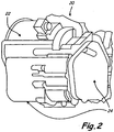
- Each of generators 20 includes motor 22 and oil system 24 shown in FIG. 2 , which is a detail view of one generator 20 of FIG. 1 .
- oil system 24 may include an oil pump fluidly connected to motor 22 and a reservoir fluidly connected to the pump and motor 22.
- FIG. 3 is a schematic section view of engine 10 shown in FIG. 1 including fan section 12, nacelle 16, accessory gearbox 18, generator 20, and gaps 26, 28 (shown schematically as circles).
- Generator 20 includes generator motor 22 and oil system 24.
- the size and arrangement of generator 20 in engine 10 defines the shape of nacelle 16 adjacent generator 20.
- gaps 26, 28 define a distance between two maximum radial dimensions of generator 20 and two points on nacelle 16 adjacent generator 20.
- Gaps 26, 28 represent clearance distances between generator 20 arid nacelle 16, which act as a limiting design constraint on the aerodynamic shape of nacelle 16.
- the size of generator 20 necessitates a radially outward bulge in nacelle 16 at gap distances 26, 28.
- the bulge in the shape of nacelle 16 surrounding generator 20 degrades the efficiency of engine 10 by acting to remove energy from the working medium gas as it travels over the bulged surface.
- FIG. 4 is a schematic section view of an embodiment of gas turbine engine 30 according to the present invention including nacelle 16, gearbox 18, and generator 32.
- Generator 32 includes motor 32a, one or more fluid connections 32b, and oil system 32c.
- generator motor 32a is mounted on an aft side of gearbox 18.
- Gearbox 18 may be driven directly or indirectly by a main shaft of engine 30, for example the compressor shaft, and in turn gearbox 18 drives generator motor 32a.
- Generator oil system 32c which may include a pump and a reservoir, is offset from motor 32a, for example, offset axially from motor 32a and mounted on a forward side of gearbox 18 as shown in FIG. 4 .
- oil system 32c may be radially offset from motor 32a.
- Oil system 32c may be driven by gearbox 18 and connected to motor 32a by fluid connections 32b.
- the pump of oil system 32c is driven by gearbox 18 and fluidly connected to motor 32a by fluid connections 32b.
- the pump may be configured to supply motor 32a with oil drawn from the reservoir, which is fluidly connected to the pump and motor 32a by fluid connections 32b.
- the maximum radial dimension of generator 32 has been significantly reduced by offsetting oil system 32c from motor 32a. Reducing the maximum radial dimension of generator 32 significantly reduces the limiting effect of clearance gaps 26, 28 on the aerodynamic shape of nacelle 16. As shown in FIG. 4 , the radial bulge in the shape of nacelle 16 surrounding generator 32 has been substantially reduced, while maintaining the required clearance gaps 26, 28 between generator 32 and nacelle 16. The size of generator 32 may be further reduced, and in turn the aerodynamic shape of nacelle 16 further improved, by contouring the bottom surface of housing 34 surrounding generator motor 32a as shown in FIG. 5 , which is a perspective view of generator motor 32a of FIG. 4 .
- Generators according to the present invention may include oil systems arranged in various locations offset the generator motors to which they supply oil.
- generator 32 may include oil system 32c located inside nacelle 16 and radially offset from generator 32 and accessory gearbox 18 about the main axis of engine 30.
- oil system 32c may be driven by a small electric motor and fluidly connected to generator motor 32a mounted to gearbox 18.
- Another embodiment may include arranging generator oil system 32c in the fan section 12.
- Generators according to the present invention have several advantages over prior generators used in gas turbine engines.
- the size of generators according to the present invention is significantly reduced by offsetting the oil system from the generator motor. Reducing the size of the generator reduces the maximum radial dimension of the generator from the main axis of the engine to which the generator is attached. Reducing the maximum radial dimension of generators according to the present invention in turn reduces the limiting effect of the generator size on the aerodynamic shape of the nacelle surrounding the generator.
- generators according to the present invention improve the aerodynamic shape of the nacelle by significantly reducing the size of the radially outward bulge in the nacelle surrounding the generator. Improving the aerodynamic shape of the nacelle significantly improves overall engine efficiency, which in turn reduces operation costs by improving fuel economy.
Landscapes
- Engineering & Computer Science (AREA)
- Chemical & Material Sciences (AREA)
- Combustion & Propulsion (AREA)
- Mechanical Engineering (AREA)
- General Engineering & Computer Science (AREA)
- Connection Of Motors, Electrical Generators, Mechanical Devices, And The Like (AREA)
- Wind Motors (AREA)
- Structures Of Non-Positive Displacement Pumps (AREA)
Claims (12)
- Zusatzsystem, das in einem Gasturbinentriebwerk (30) verwendet wird, wobei das System Folgendes umfasst:ein Getriebe (18), das von einer Welle des Gasturbinentriebwerks (30) angetrieben wird;einen elektrischen Generator (32), der mit dem Getriebe (18) verbunden ist;ein Generatorölsystem (32c), das mit dem Getriebe (18) verbunden ist; undeine oder mehrere Fluidverbindungen (32b) zwischen dem elektrischen Generator (32) und dem Generatorölsystem (32c);wobei das Getriebe (18), der elektrische Generator (32) und das Generatorölsystem (32c) dazu konfiguriert sind, radial außerhalb einer Hauptachse des Gasturbinentriebwerks (30) und innerhalb einer Gondel (16) angeordnet zu sein; undwobei das Generatorölsystem (32c) von dem elektrischen Generator (32) versetzt ist, derart, dass das Generatorölsystem (32c) nicht radial außerhalb des elektrischen Generators (32) angeordnet ist, dadurch gekennzeichnet, dass:der elektrische Generator (32) mit einer Hinterseite des Getriebes (18) verbunden ist und das Generatorölsystem (32c) mit einer Vorderseite des Getriebes (18) verbunden ist.
- System nach Anspruch 1, wobei das Generatorölsystem (32c) von dem elektrischen Motor (32a) oder dem elektrischen Generator (32) axial versetzt ist.
- System nach Anspruch 1, wobei das Generatorölsystem (32c) von dem elektrischen Motor (32a) oder dem elektrischen Generator (32) in Umfangsrichtung versetzt ist.
- System nach Anspruch 1, wobei das Generatorölsystem (32c) von dem elektrischen Motor (32) oder dem elektrischen Generator (32) axial und in Umfangsrichtung versetzt ist.
- System nach einem der vorangehenden Ansprüche, wobei das Generatorölsystem (32c) von dem Generatormotor (32a) versetzt ist, um eine oder mehrere radiale Abmessungen der Generatorbaugruppe (32) von der Hauptachse des Gasturbinentriebwerks (30) zu reduzieren, oder wobei der elektrische Generator (32) und das Generatorölsystem (32c) dazu angeordnet sind, eine oder mehrere radiale Abmessungen des Zusatzsystems von der Hauptachse des Gasturbinentriebwerks (30) zu reduzieren.
- System nach einem der vorangehenden Ansprüche, wobei das Generatorölsystem (32c) von dem Generatormotor (32a) versetzt ist, um Freiraum bereitzustellen, um eine oder mehrere radiale Abmessungen der Gondel (16) von der Hauptachse des Gasturbinentriebwerks (30) zu reduzieren, oder wobei der elektrische Generator (32) und das Generatorölsystem (32c) dazu angeordnet sind, Freiraum bereitzustellen, um eine oder mehrere radiale Abmessungen der Gondel (16) von der Hauptachse des Gasturbinentriebwerks (30) zu reduzieren.
- System nach einem der vorangehenden Ansprüche, wobei der elektrische Motor (32a) ferner Folgendes umfasst:ein Gehäuse, das dazu konturiert ist, eine oder mehrere radiale Abmessungen der Generatorbaugruppe (32) von der Hauptachse des Gasturbinentriebwerks (30) zu reduzieren, oder der elektrische Generator (32) ferner Folgendes umfasst:ein Gehäuse, das dazu konturiert ist, eine oder mehrere radiale Abmessungen des elektrischen Generators (32) von der Hauptachse des Gasturbinentriebwerks (30) zu reduzieren.
- System nach Anspruch 7, wobei das konturierte Gehäuse dazu konfiguriert ist, Freiraum zum Reduzieren einer oder mehrerer radialer Abmessungen der Gondel (16) von der Hauptachse des Gasturbinentriebwerks (30) bereitzustellen.
- System nach einem der Ansprüche 2 bis 8, wobei das Generatorölsystem (32c) dazu konfiguriert ist, mit dem Zusatzgetriebe (18) verbunden zu sein.
- System nach einem der Ansprüche 2 bis 9, wobei das Generatorölsystem (32c) ferner Folgendes umfasst:wenigstens eine Pumpe, die dazu konfiguriert ist, mit dem Zusatzgetriebe (18) verbunden zu sein; undwenigstens einen Behälter, der in Fluidverbindung mit der Pumpe und mit dem elektrischen Motor (32a) steht.
- System nach einem der Ansprüche 1 bis 8, wobei das Generatorölsystem (32c) ferner Folgendes umfasst:wenigstens eine Pumpe, die mit dem Zusatzgetriebe (18) verbunden ist; undwenigstens einen Behälter, der in Fluidverbindung mit der Pumpe und mit dem elektrischen Generator (32) steht.
- Gasturbinentriebwerk, umfassend:einen Gebläseabschnitt (12), einen Verdichterabschnitt, eine Brennkammer und einen Turbinenabschnitt;eine Gondel (16), die hinten aus dem Gebläseabschnitt (12) heraustritt und den Verdichterabschnitt, die Brennkammer und den Turbinenabschnitt umgibt; unddas Zusatzsystem nach Anspruch 1, wobei das System hinter dem Gebläseabschnitt (12) radial außerhalb des Verdichterabschnitts, der Brennkammer und des Turbinenabschnitts und innerhalb der Gondel (16) angeordnet ist.
Applications Claiming Priority (1)
| Application Number | Priority Date | Filing Date | Title |
|---|---|---|---|
| US11/823,652 US8312728B2 (en) | 2007-06-28 | 2007-06-28 | Generator with separate oil system for improved nacelle performance |
Publications (3)
| Publication Number | Publication Date |
|---|---|
| EP2011979A2 EP2011979A2 (de) | 2009-01-07 |
| EP2011979A3 EP2011979A3 (de) | 2013-03-20 |
| EP2011979B1 true EP2011979B1 (de) | 2016-12-14 |
Family
ID=40028212
Family Applications (1)
| Application Number | Title | Priority Date | Filing Date |
|---|---|---|---|
| EP08252157.6A Active EP2011979B1 (de) | 2007-06-28 | 2008-06-23 | Generator mit separatem Ölsystem |
Country Status (2)
| Country | Link |
|---|---|
| US (1) | US8312728B2 (de) |
| EP (1) | EP2011979B1 (de) |
Families Citing this family (20)
| Publication number | Priority date | Publication date | Assignee | Title |
|---|---|---|---|---|
| US8438859B2 (en) * | 2008-01-08 | 2013-05-14 | Rolls-Royce North American Technologies, Inc. | Integrated bypass engine structure |
| FR2941744B1 (fr) * | 2009-01-30 | 2011-09-16 | Hispano Suiza Sa | Ensemble d'un boitier de relais d'accessoires et d'un reservoir d'huile |
| US9816441B2 (en) * | 2009-03-30 | 2017-11-14 | United Technologies Corporation | Gas turbine engine with stacked accessory components |
| US8424416B2 (en) | 2010-06-18 | 2013-04-23 | Hamilton Sundstrand Corporation | Layshaft generator |
| DE102011112254A1 (de) * | 2011-09-02 | 2013-03-07 | Rolls-Royce Deutschland Ltd & Co Kg | Triebwerk für ein Luftfahrzeug mit einer Tankvorrichtung |
| US9163562B2 (en) * | 2012-03-14 | 2015-10-20 | United Technologies Corporation | Constant speed pump system for engine ECS loss elimination |
| WO2013165771A1 (en) * | 2012-04-30 | 2013-11-07 | United Technologies Corporation | Geared turbofan with distributed accessory gearboxes |
| US9194294B2 (en) | 2012-05-07 | 2015-11-24 | United Technologies Corporation | Gas turbine engine oil tank |
| EP2898205B1 (de) * | 2012-09-20 | 2021-11-24 | Raytheon Technologies Corporation | Hilfsgetriebe für gasturbinenmotor |
| US10294870B2 (en) | 2013-03-15 | 2019-05-21 | United Technologies Corporation | Distributed engine accessory drive |
| US10634061B2 (en) * | 2014-03-06 | 2020-04-28 | United Technologies Corporation | Gas turbine engine accessory architecture |
| US9917490B2 (en) * | 2014-11-21 | 2018-03-13 | Hamilton Sundstrand Corporation | Tail cone generator with integral speed increasing gearbox |
| US20160230843A1 (en) * | 2015-02-09 | 2016-08-11 | United Technologies Corporation | Gearbox for gas turbine engine |
| US10570824B2 (en) * | 2015-11-23 | 2020-02-25 | United Technologies Corporation | Near zero velocity lubrication system for a turbine engine |
| US10329955B2 (en) | 2016-01-27 | 2019-06-25 | Pratt & Whitney Canada Corp. | Oil system for turbine engine and related method |
| GB201616759D0 (en) * | 2016-10-03 | 2016-11-16 | Rolls Royce Deutschland Ltd & Co Kg | Accessory gearbox for a gas turbine engine |
| US10422243B2 (en) * | 2017-01-19 | 2019-09-24 | United Technologies Corporation | Gas turbine engine dual towershaft accessory gearbox and starter generator assembly |
| US10590852B2 (en) * | 2017-01-19 | 2020-03-17 | United Technologies Corporation | Gas turbine engine dual towershaft accessory gearbox assembly with a transmission |
| WO2018174514A1 (ko) * | 2017-03-24 | 2018-09-27 | 광주과학기술원 | 다중레벨 저항 및 정전용량 메모리 특성을 갖는 비휘발성 메모리 소자 및 그 제조방법 |
| US11959589B2 (en) | 2022-04-11 | 2024-04-16 | Hamilton Sundstrand Corporation | Motor driven pump for variable speed power generation cooling |
Family Cites Families (17)
| Publication number | Priority date | Publication date | Assignee | Title |
|---|---|---|---|---|
| US2566049A (en) * | 1948-02-07 | 1951-08-28 | Packard Motor Car Co | Accessory drive for turbo-jet engines |
| US3806067A (en) * | 1971-08-30 | 1974-04-23 | Gen Electric | Area ruled nacelle |
| US4147029A (en) * | 1976-01-02 | 1979-04-03 | General Electric Company | Long duct mixed flow gas turbine engine |
| US4474001A (en) * | 1981-04-01 | 1984-10-02 | United Technologies Corporation | Cooling system for the electrical generator of a turbofan gas turbine engine |
| US4437627A (en) * | 1982-03-12 | 1984-03-20 | The Boeing Company | Integrated power plant installation system |
| GB2260577B (en) * | 1991-10-16 | 1994-10-05 | Rolls Royce Plc | Gas turbine engine starting |
| US5636708A (en) * | 1994-05-16 | 1997-06-10 | Wedeven; Lavern D. | Method and device for broad temperature range vapor lubrication |
| US6851267B2 (en) * | 2002-12-18 | 2005-02-08 | Pratt & Whitney Canada Corp. | Compact quick attach starter-generator installation |
| US6945031B2 (en) * | 2003-02-21 | 2005-09-20 | The Nordam Group, Inc. | Recessed engine nacelle |
| GB0311663D0 (en) * | 2003-05-21 | 2003-06-25 | Rolls Royce Plc | Aeroengine intake |
| US7090165B2 (en) * | 2003-06-02 | 2006-08-15 | Rolls-Royce Plc | Aeroengine nacelle |
| GB0315894D0 (en) | 2003-07-08 | 2003-08-13 | Rolls Royce Plc | Aircraft engine arrangement |
| US7105937B2 (en) * | 2004-07-14 | 2006-09-12 | Hamilton Sundstrand Corporation | Adjustable variable frequency starter/generator system |
| US7116003B2 (en) * | 2004-07-14 | 2006-10-03 | Hamilton Sundstrand Corporation | Aircraft starter/generator electrical system with mixed power architecture |
| US7104072B2 (en) * | 2004-08-16 | 2006-09-12 | Hamilton Sundstrand Corporation | Combined power main engine start system |
| US7117683B2 (en) * | 2004-08-25 | 2006-10-10 | Hamilton Sundstrand Corporation | Main engine electric start system |
| US7500365B2 (en) | 2005-05-05 | 2009-03-10 | United Technologies Corporation | Accessory gearbox |
-
2007
- 2007-06-28 US US11/823,652 patent/US8312728B2/en active Active
-
2008
- 2008-06-23 EP EP08252157.6A patent/EP2011979B1/de active Active
Non-Patent Citations (1)
| Title |
|---|
| None * |
Also Published As
| Publication number | Publication date |
|---|---|
| US8312728B2 (en) | 2012-11-20 |
| EP2011979A3 (de) | 2013-03-20 |
| US20090000308A1 (en) | 2009-01-01 |
| EP2011979A2 (de) | 2009-01-07 |
Similar Documents
| Publication | Publication Date | Title |
|---|---|---|
| US8312728B2 (en) | Generator with separate oil system for improved nacelle performance | |
| EP2584174B1 (de) | Windmühlenbetrieb eines Gasturbinenmotors | |
| US10941706B2 (en) | Closed cycle heat engine for a gas turbine engine | |
| EP2584172B1 (de) | Getriebe mit konstanter Drehzahl für Gasturbinen-Motor | |
| EP3260688B1 (de) | Kammerkühlung für einen gasturbinenmotor | |
| EP2584168B1 (de) | Integriertes wärmesystem für einen gasturbinenmotor | |
| EP2085589B2 (de) | Anordnung von Hilfsaggregaten, entsprechende Getriebevorrichtung und Gasturbinentriebwerk | |
| EP2584169B1 (de) | Gasturbinenmotor mit Integriertem Wärmeverwaltungssystem | |
| EP2584175B1 (de) | Gasturbinenmotor und verfahren zum betrieb davon | |
| US8205426B2 (en) | Method and apparatus for operating gas turbine engines | |
| EP2617966B1 (de) | Gasturbinenmotor-Hilfsgerätegetriebe | |
| WO2014052269A1 (en) | Off-take power ratio | |
| US9091214B2 (en) | Reduced gearbox size by separate electrically powered engine oil system | |
| CN114076035B (zh) | 具有初级和次级气流路径的空气涡轮启动器 | |
| RU2522208C1 (ru) | Пилон газотурбинного двигателя в сборе и система газотурбинного двигателя | |
| CN112443652B (zh) | 具有收集器的用于航空发动机的齿轮组件 | |
| EP2592235A2 (de) | Verdichteranordnungen für einen Gasturbinenmotor | |
| US20250075662A1 (en) | Turbine Engine having First and Second Accessory Gearboxes | |
| US20250290452A1 (en) | Turbine engine with accessory gearbox | |
| US20250154904A1 (en) | Fuel control system | |
| EP3301288B1 (de) | Hilfsgetriebe für einen gasturbinenmotor | |
| WO2013165771A1 (en) | Geared turbofan with distributed accessory gearboxes |
Legal Events
| Date | Code | Title | Description |
|---|---|---|---|
| PUAI | Public reference made under article 153(3) epc to a published international application that has entered the european phase |
Free format text: ORIGINAL CODE: 0009012 |
|
| AK | Designated contracting states |
Kind code of ref document: A2 Designated state(s): AT BE BG CH CY CZ DE DK EE ES FI FR GB GR HR HU IE IS IT LI LT LU LV MC MT NL NO PL PT RO SE SI SK TR |
|
| AX | Request for extension of the european patent |
Extension state: AL BA MK RS |
|
| PUAL | Search report despatched |
Free format text: ORIGINAL CODE: 0009013 |
|
| AK | Designated contracting states |
Kind code of ref document: A3 Designated state(s): AT BE BG CH CY CZ DE DK EE ES FI FR GB GR HR HU IE IS IT LI LT LU LV MC MT NL NO PL PT RO SE SI SK TR |
|
| AX | Request for extension of the european patent |
Extension state: AL BA MK RS |
|
| RIC1 | Information provided on ipc code assigned before grant |
Ipc: F02C 7/32 20060101AFI20130211BHEP |
|
| 17P | Request for examination filed |
Effective date: 20130920 |
|
| RBV | Designated contracting states (corrected) |
Designated state(s): AT BE BG CH CY CZ DE DK EE ES FI FR GB GR HR HU IE IS IT LI LT LU LV MC MT NL NO PL PT RO SE SI SK TR |
|
| RBV | Designated contracting states (corrected) |
Designated state(s): AT BE BG CH CY CZ DE DK EE ES FI FR GB GR HR HU IE IS IT LI LT LU LV MC MT NL NO PL PT RO SE SI SK TR |
|
| AKX | Designation fees paid |
Designated state(s): AT BE BG CH CY CZ DE DK EE ES FI FR GB GR HR HU IE IS IT LI LT LU LV MC MT NL NO PL PT RO SE SI SK TR |
|
| 17Q | First examination report despatched |
Effective date: 20131209 |
|
| GRAP | Despatch of communication of intention to grant a patent |
Free format text: ORIGINAL CODE: EPIDOSNIGR1 |
|
| INTG | Intention to grant announced |
Effective date: 20160713 |
|
| RAP1 | Party data changed (applicant data changed or rights of an application transferred) |
Owner name: UNITED TECHNOLOGIES CORPORATION |
|
| GRAS | Grant fee paid |
Free format text: ORIGINAL CODE: EPIDOSNIGR3 |
|
| GRAA | (expected) grant |
Free format text: ORIGINAL CODE: 0009210 |
|
| AK | Designated contracting states |
Kind code of ref document: B1 Designated state(s): AT BE BG CH CY CZ DE DK EE ES FI FR GB GR HR HU IE IS IT LI LT LU LV MC MT NL NO PL PT RO SE SI SK TR |
|
| REG | Reference to a national code |
Ref country code: GB Ref legal event code: FG4D |
|
| REG | Reference to a national code |
Ref country code: CH Ref legal event code: EP |
|
| REG | Reference to a national code |
Ref country code: IE Ref legal event code: FG4D |
|
| REG | Reference to a national code |
Ref country code: AT Ref legal event code: REF Ref document number: 853811 Country of ref document: AT Kind code of ref document: T Effective date: 20170115 |
|
| REG | Reference to a national code |
Ref country code: DE Ref legal event code: R096 Ref document number: 602008047846 Country of ref document: DE |
|
| PG25 | Lapsed in a contracting state [announced via postgrant information from national office to epo] |
Ref country code: LV Free format text: LAPSE BECAUSE OF FAILURE TO SUBMIT A TRANSLATION OF THE DESCRIPTION OR TO PAY THE FEE WITHIN THE PRESCRIBED TIME-LIMIT Effective date: 20161214 |
|
| REG | Reference to a national code |
Ref country code: LT Ref legal event code: MG4D |
|
| REG | Reference to a national code |
Ref country code: NL Ref legal event code: MP Effective date: 20161214 |
|
| PG25 | Lapsed in a contracting state [announced via postgrant information from national office to epo] |
Ref country code: LT Free format text: LAPSE BECAUSE OF FAILURE TO SUBMIT A TRANSLATION OF THE DESCRIPTION OR TO PAY THE FEE WITHIN THE PRESCRIBED TIME-LIMIT Effective date: 20161214 Ref country code: GR Free format text: LAPSE BECAUSE OF FAILURE TO SUBMIT A TRANSLATION OF THE DESCRIPTION OR TO PAY THE FEE WITHIN THE PRESCRIBED TIME-LIMIT Effective date: 20170315 Ref country code: SE Free format text: LAPSE BECAUSE OF FAILURE TO SUBMIT A TRANSLATION OF THE DESCRIPTION OR TO PAY THE FEE WITHIN THE PRESCRIBED TIME-LIMIT Effective date: 20161214 Ref country code: NO Free format text: LAPSE BECAUSE OF FAILURE TO SUBMIT A TRANSLATION OF THE DESCRIPTION OR TO PAY THE FEE WITHIN THE PRESCRIBED TIME-LIMIT Effective date: 20170314 |
|
| REG | Reference to a national code |
Ref country code: AT Ref legal event code: MK05 Ref document number: 853811 Country of ref document: AT Kind code of ref document: T Effective date: 20161214 |
|
| REG | Reference to a national code |
Ref country code: FR Ref legal event code: PLFP Year of fee payment: 10 |
|
| PG25 | Lapsed in a contracting state [announced via postgrant information from national office to epo] |
Ref country code: HR Free format text: LAPSE BECAUSE OF FAILURE TO SUBMIT A TRANSLATION OF THE DESCRIPTION OR TO PAY THE FEE WITHIN THE PRESCRIBED TIME-LIMIT Effective date: 20161214 Ref country code: FI Free format text: LAPSE BECAUSE OF FAILURE TO SUBMIT A TRANSLATION OF THE DESCRIPTION OR TO PAY THE FEE WITHIN THE PRESCRIBED TIME-LIMIT Effective date: 20161214 |
|
| PG25 | Lapsed in a contracting state [announced via postgrant information from national office to epo] |
Ref country code: NL Free format text: LAPSE BECAUSE OF FAILURE TO SUBMIT A TRANSLATION OF THE DESCRIPTION OR TO PAY THE FEE WITHIN THE PRESCRIBED TIME-LIMIT Effective date: 20161214 |
|
| REG | Reference to a national code |
Ref country code: DE Ref legal event code: R082 Ref document number: 602008047846 Country of ref document: DE Representative=s name: SCHMITT-NILSON SCHRAUD WAIBEL WOHLFROM PATENTA, DE |
|
| PG25 | Lapsed in a contracting state [announced via postgrant information from national office to epo] |
Ref country code: IS Free format text: LAPSE BECAUSE OF FAILURE TO SUBMIT A TRANSLATION OF THE DESCRIPTION OR TO PAY THE FEE WITHIN THE PRESCRIBED TIME-LIMIT Effective date: 20170414 Ref country code: CZ Free format text: LAPSE BECAUSE OF FAILURE TO SUBMIT A TRANSLATION OF THE DESCRIPTION OR TO PAY THE FEE WITHIN THE PRESCRIBED TIME-LIMIT Effective date: 20161214 Ref country code: SK Free format text: LAPSE BECAUSE OF FAILURE TO SUBMIT A TRANSLATION OF THE DESCRIPTION OR TO PAY THE FEE WITHIN THE PRESCRIBED TIME-LIMIT Effective date: 20161214 Ref country code: EE Free format text: LAPSE BECAUSE OF FAILURE TO SUBMIT A TRANSLATION OF THE DESCRIPTION OR TO PAY THE FEE WITHIN THE PRESCRIBED TIME-LIMIT Effective date: 20161214 Ref country code: RO Free format text: LAPSE BECAUSE OF FAILURE TO SUBMIT A TRANSLATION OF THE DESCRIPTION OR TO PAY THE FEE WITHIN THE PRESCRIBED TIME-LIMIT Effective date: 20161214 |
|
| PG25 | Lapsed in a contracting state [announced via postgrant information from national office to epo] |
Ref country code: PL Free format text: LAPSE BECAUSE OF FAILURE TO SUBMIT A TRANSLATION OF THE DESCRIPTION OR TO PAY THE FEE WITHIN THE PRESCRIBED TIME-LIMIT Effective date: 20161214 Ref country code: PT Free format text: LAPSE BECAUSE OF FAILURE TO SUBMIT A TRANSLATION OF THE DESCRIPTION OR TO PAY THE FEE WITHIN THE PRESCRIBED TIME-LIMIT Effective date: 20170414 Ref country code: BG Free format text: LAPSE BECAUSE OF FAILURE TO SUBMIT A TRANSLATION OF THE DESCRIPTION OR TO PAY THE FEE WITHIN THE PRESCRIBED TIME-LIMIT Effective date: 20170314 Ref country code: AT Free format text: LAPSE BECAUSE OF FAILURE TO SUBMIT A TRANSLATION OF THE DESCRIPTION OR TO PAY THE FEE WITHIN THE PRESCRIBED TIME-LIMIT Effective date: 20161214 Ref country code: BE Free format text: LAPSE BECAUSE OF FAILURE TO SUBMIT A TRANSLATION OF THE DESCRIPTION OR TO PAY THE FEE WITHIN THE PRESCRIBED TIME-LIMIT Effective date: 20161214 Ref country code: ES Free format text: LAPSE BECAUSE OF FAILURE TO SUBMIT A TRANSLATION OF THE DESCRIPTION OR TO PAY THE FEE WITHIN THE PRESCRIBED TIME-LIMIT Effective date: 20161214 Ref country code: IT Free format text: LAPSE BECAUSE OF FAILURE TO SUBMIT A TRANSLATION OF THE DESCRIPTION OR TO PAY THE FEE WITHIN THE PRESCRIBED TIME-LIMIT Effective date: 20161214 |
|
| REG | Reference to a national code |
Ref country code: DE Ref legal event code: R097 Ref document number: 602008047846 Country of ref document: DE |
|
| PLBE | No opposition filed within time limit |
Free format text: ORIGINAL CODE: 0009261 |
|
| STAA | Information on the status of an ep patent application or granted ep patent |
Free format text: STATUS: NO OPPOSITION FILED WITHIN TIME LIMIT |
|
| 26N | No opposition filed |
Effective date: 20170915 |
|
| PG25 | Lapsed in a contracting state [announced via postgrant information from national office to epo] |
Ref country code: DK Free format text: LAPSE BECAUSE OF FAILURE TO SUBMIT A TRANSLATION OF THE DESCRIPTION OR TO PAY THE FEE WITHIN THE PRESCRIBED TIME-LIMIT Effective date: 20161214 |
|
| PG25 | Lapsed in a contracting state [announced via postgrant information from national office to epo] |
Ref country code: MC Free format text: LAPSE BECAUSE OF FAILURE TO SUBMIT A TRANSLATION OF THE DESCRIPTION OR TO PAY THE FEE WITHIN THE PRESCRIBED TIME-LIMIT Effective date: 20161214 |
|
| REG | Reference to a national code |
Ref country code: CH Ref legal event code: PL |
|
| PG25 | Lapsed in a contracting state [announced via postgrant information from national office to epo] |
Ref country code: SI Free format text: LAPSE BECAUSE OF FAILURE TO SUBMIT A TRANSLATION OF THE DESCRIPTION OR TO PAY THE FEE WITHIN THE PRESCRIBED TIME-LIMIT Effective date: 20161214 |
|
| REG | Reference to a national code |
Ref country code: IE Ref legal event code: MM4A |
|
| PG25 | Lapsed in a contracting state [announced via postgrant information from national office to epo] |
Ref country code: LI Free format text: LAPSE BECAUSE OF NON-PAYMENT OF DUE FEES Effective date: 20170630 Ref country code: IE Free format text: LAPSE BECAUSE OF NON-PAYMENT OF DUE FEES Effective date: 20170623 Ref country code: CH Free format text: LAPSE BECAUSE OF NON-PAYMENT OF DUE FEES Effective date: 20170630 Ref country code: LU Free format text: LAPSE BECAUSE OF NON-PAYMENT OF DUE FEES Effective date: 20170623 |
|
| REG | Reference to a national code |
Ref country code: FR Ref legal event code: PLFP Year of fee payment: 11 |
|
| PG25 | Lapsed in a contracting state [announced via postgrant information from national office to epo] |
Ref country code: MT Free format text: LAPSE BECAUSE OF NON-PAYMENT OF DUE FEES Effective date: 20170623 |
|
| PG25 | Lapsed in a contracting state [announced via postgrant information from national office to epo] |
Ref country code: HU Free format text: LAPSE BECAUSE OF FAILURE TO SUBMIT A TRANSLATION OF THE DESCRIPTION OR TO PAY THE FEE WITHIN THE PRESCRIBED TIME-LIMIT; INVALID AB INITIO Effective date: 20080623 |
|
| PG25 | Lapsed in a contracting state [announced via postgrant information from national office to epo] |
Ref country code: CY Free format text: LAPSE BECAUSE OF NON-PAYMENT OF DUE FEES Effective date: 20161214 |
|
| PG25 | Lapsed in a contracting state [announced via postgrant information from national office to epo] |
Ref country code: TR Free format text: LAPSE BECAUSE OF FAILURE TO SUBMIT A TRANSLATION OF THE DESCRIPTION OR TO PAY THE FEE WITHIN THE PRESCRIBED TIME-LIMIT Effective date: 20161214 |
|
| REG | Reference to a national code |
Ref country code: DE Ref legal event code: R081 Ref document number: 602008047846 Country of ref document: DE Owner name: RAYTHEON TECHNOLOGIES CORPORATION (N.D.GES.D.S, US Free format text: FORMER OWNER: UNITED TECHNOLOGIES CORPORATION, FARMINGTON, CONN., US Ref country code: DE Ref legal event code: R081 Ref document number: 602008047846 Country of ref document: DE Owner name: RTX CORPORATION (N.D.GES.D. STAATES DELAWARE),, US Free format text: FORMER OWNER: UNITED TECHNOLOGIES CORPORATION, FARMINGTON, CONN., US |
|
| P01 | Opt-out of the competence of the unified patent court (upc) registered |
Effective date: 20230519 |
|
| REG | Reference to a national code |
Ref country code: DE Ref legal event code: R081 Ref document number: 602008047846 Country of ref document: DE Owner name: RTX CORPORATION (N.D.GES.D. STAATES DELAWARE),, US Free format text: FORMER OWNER: RAYTHEON TECHNOLOGIES CORPORATION (N.D.GES.D.STAATES DELAWARE), ARLINGTON, VA, US |
|
| PGFP | Annual fee paid to national office [announced via postgrant information from national office to epo] |
Ref country code: GB Payment date: 20260525 Year of fee payment: 19 |
|
| PGFP | Annual fee paid to national office [announced via postgrant information from national office to epo] |
Ref country code: DE Payment date: 20260520 Year of fee payment: 19 |
|
| PGFP | Annual fee paid to national office [announced via postgrant information from national office to epo] |
Ref country code: FR Payment date: 20260520 Year of fee payment: 19 |