EP2011972B1 - Anlage, Verfahren und Vorrichtung zur Erzeugung eines überhitzten Mediums - Google Patents
Anlage, Verfahren und Vorrichtung zur Erzeugung eines überhitzten Mediums Download PDFInfo
- Publication number
- EP2011972B1 EP2011972B1 EP08011891.2A EP08011891A EP2011972B1 EP 2011972 B1 EP2011972 B1 EP 2011972B1 EP 08011891 A EP08011891 A EP 08011891A EP 2011972 B1 EP2011972 B1 EP 2011972B1
- Authority
- EP
- European Patent Office
- Prior art keywords
- heat transfer
- transfer medium
- steam
- medium
- furnace
- Prior art date
- Legal status (The legal status is an assumption and is not a legal conclusion. Google has not performed a legal analysis and makes no representation as to the accuracy of the status listed.)
- Active
Links
Images


Classifications
-
- F—MECHANICAL ENGINEERING; LIGHTING; HEATING; WEAPONS; BLASTING
- F23—COMBUSTION APPARATUS; COMBUSTION PROCESSES
- F23G—CREMATION FURNACES; CONSUMING WASTE PRODUCTS BY COMBUSTION
- F23G5/00—Incineration of waste; Incinerator constructions; Details, accessories or control therefor
- F23G5/44—Details; Accessories
- F23G5/46—Recuperation of heat
-
- F—MECHANICAL ENGINEERING; LIGHTING; HEATING; WEAPONS; BLASTING
- F22—STEAM GENERATION
- F22B—METHODS OF STEAM GENERATION; STEAM BOILERS
- F22B1/00—Methods of steam generation characterised by form of heating method
- F22B1/02—Methods of steam generation characterised by form of heating method by exploitation of the heat content of hot heat carriers
- F22B1/18—Methods of steam generation characterised by form of heating method by exploitation of the heat content of hot heat carriers the heat carrier being a hot gas, e.g. waste gas such as exhaust gas of internal-combustion engines
-
- F—MECHANICAL ENGINEERING; LIGHTING; HEATING; WEAPONS; BLASTING
- F23—COMBUSTION APPARATUS; COMBUSTION PROCESSES
- F23M—CASINGS, LININGS, WALLS OR DOORS SPECIALLY ADAPTED FOR COMBUSTION CHAMBERS, e.g. FIREBRIDGES; DEVICES FOR DEFLECTING AIR, FLAMES OR COMBUSTION PRODUCTS IN COMBUSTION CHAMBERS; SAFETY ARRANGEMENTS SPECIALLY ADAPTED FOR COMBUSTION APPARATUS; DETAILS OF COMBUSTION CHAMBERS, NOT OTHERWISE PROVIDED FOR
- F23M5/00—Casings; Linings; Walls
- F23M5/08—Cooling thereof; Tube walls
-
- Y—GENERAL TAGGING OF NEW TECHNOLOGICAL DEVELOPMENTS; GENERAL TAGGING OF CROSS-SECTIONAL TECHNOLOGIES SPANNING OVER SEVERAL SECTIONS OF THE IPC; TECHNICAL SUBJECTS COVERED BY FORMER USPC CROSS-REFERENCE ART COLLECTIONS [XRACs] AND DIGESTS
- Y02—TECHNOLOGIES OR APPLICATIONS FOR MITIGATION OR ADAPTATION AGAINST CLIMATE CHANGE
- Y02E—REDUCTION OF GREENHOUSE GAS [GHG] EMISSIONS, RELATED TO ENERGY GENERATION, TRANSMISSION OR DISTRIBUTION
- Y02E20/00—Combustion technologies with mitigation potential
- Y02E20/12—Heat utilisation in combustion or incineration of waste
Definitions
- the invention relates to a method and a device or a system for generating a superheated medium, in particular of steam or a vapor-gas mixture, and for reducing corrosion in combustion chambers, which are designed as a boiler, and superheaters in thermal waste incinerators and thermal bio -mass incinerators.
- the present invention relates to the incineration or recycling of waste, biomass and hazardous waste, hereinafter referred to collectively as special fuels.
- Special fuels are thus to be understood as meaning all fuels in which flue gas constituents in the flue gas for the combustion chamber, the boiler and the downstream plant components present or may be present are corrosive and / or flue gas constituents which tend toward slagging.
- Such corrosive and / or slagging substances are chlorine and sulfur compounds and / or reduced in melting point ashes, which may for example have a high alkali content.
- FIG. 1 a method is known in which the heating of the heat transfer medium takes place in a separate heater, which is fed by combustion gases derived from the furnace.
- FR 2 836 715 revealed in FIG. 5 a plant in which the superheater is located outside the furnace and is heated by a recirculating heat transfer medium.
- the heat transfer medium is heated directly in arranged within the combustion chamber pipes.
- the object is an efficient and economically feasible overheating of saturated steam to more than 400 ° C, preferably to at least 500 ° C, and at a vapor pressure of at least 150 bar to allow special fuel systems while reducing corrosion in the boiler.
- the present invention relates in particular to the incineration or recycling of waste / garbage, biofuels / biomass, special / hazardous waste, industrial waste / industrial waste, hereinafter referred to collectively as special fuels.
- Special fuels are therefore to be understood as meaning all fuels which, in the described temperature range, cause boiler corrosion associated with mostly significant losses in service life and availability.
- steam boiler steam generator
- heat exchanger heat exchanger
- the term heat exchanger is used for any indirect heat transfer device.
- the term steam generator is primarily used in the episode.
- a preferred embodiment is a steam boiler.
- conventional heat exchangers are generally used, such as single-stage or multi-stage heat exchangers with reheater and / or injection.
- the second heat exchanger which serves to overheat the steam generated in the first heat exchanger, is referred to in the sequence primarily as a superheater.
- neither the term steam generator nor the term superheater should be construed as limited to a particular embodiment.
- a medium with a temperature up to a maximum of 400 ° C. is understood to mean slightly overheated medium (medium after steam generator), in particular slightly superheated steam, under superheated medium (medium after superheater), in particular superheated steam, a medium having a temperature of more than 400 ° C, in particular more than 500 ° C.
- the superheater 9 is connected to a high-pressure steam turbine 8 via a line 16 such that superheated medium exiting from the superheater 9 is conducted as a driving force to the high-pressure steam turbine 8 (see FIG FIG. 1 ) and the furnace 2 has a combustion chamber, which is bricked up substantially of refractory ceramic parts, obei channel-shaped cavities 18 are inserted for carrying out / passage of a gaseous carrier medium in the walls 7 formed of refractory material of the combustion chamber.
- a medium bypass 15a may be provided, such that the hot to slightly superheated medium, in particular the saturated steam, wet steam or slightly superheated steam, from the steam generator 3 wholly or partially passed through an integrated heat exchanger in the furnace 2 becomes.
- a heat exchanger may be at least one combustion chamber wall provided with a tube system 7, preferably a plurality of such designed combustion chamber walls 7. This heat exchanger in the furnace 2 itself may be preceded by another heat exchanger 9a, which is heated with the exiting from the superheater 9 heat transfer medium.
- the inventive method for producing superheated medium, in particular steam, in plants, as described above, is characterized by the fact that heat contained in the hot exhaust gases formed during combustion, on the one hand to a medium flowing through the steam generator 3, in particular water / Steam, on the other hand, on a the walls 7 of the furnace 2 by flowing heat transfer medium.
- the from a first stage (main plant) after steam generation by means of the originating from the furnace 2 exhaust gases removed medium, in particular saturated steam, wet steam or slightly superheated steam is transferred to a second stage (auxiliary system) and there by means of a heat exchanger, respectively.
- Superheater 9 overheated and can then be fed to a high-pressure steam turbine 8 for power generation or a high-pressure steam consumers.
- the superheater 9 is fed with a gaseous heat transfer medium, preferably air, steam or air-steam mixtures as heat transfer medium, which were heated in the equipped with channel-shaped cavities 18 combustion chamber walls 7, which surround the furnace 2, without additional energy.
- a gaseous heat transfer medium preferably air, steam or air-steam mixtures as heat transfer medium, which were heated in the equipped with channel-shaped cavities 18 combustion chamber walls 7, which surround the furnace 2, without additional energy.
- 2 control units are provided.
- a first control device 17a is used to control the feed rate of the waste to be incinerated (ram speed), the grate speed and the primary air supply depending on the thermal load of the steam generator 3.
- a second control device 17b regulates the amount resp. the circulation rate of the heat transfer medium as a function of the medium production in the steam generator 3, ie in the first stage and / or in dependence of the steam temperature after the superheater 9.
- a corresponding Schematic is in FIG. 1 shown, in particular for the control unit 17a not all active and positioning lines
- primary air entry into different grate zones can be provided.
- Increasing the primary air supply can be compensated by reducing the secondary air injected into the post-combustion chamber and / or the recycled flue gases, so that the exhaust air quantity can be kept constant.
- the combustion air, in particular the primary air can be preheated before it is fed into the combustion chamber.
- Another advantage of the oven according to the invention is its inertia caused by the ceramic walls, which largely levels out short-term fluctuations in the calorific value.
- the main plant (first stage) and the secondary plant (second stage) are connected by a water-steam cycle.
- This thermoelectric coupling between the main plant as Dampfzeugerresp. Evaporator plant and the auxiliary system as an external, working without additional fuel use superheater system, compared to the previously known methods has the advantage that the secondary system can be operated as a superheater without evaporator part and without additional firing and the investment costs compared to one integrated into the main plant Overheater or an externally operated superheater with external auxiliary lighting are low and incur no additional fuel costs for the operation of the external superheater.
- the control device 17b serves to generate constant medium parameters (temperature, pressure) and at the same time ensures that the wall temperatures in the furnace 2 are lowered below the ash / dust softening point.
- Burners installed and operated in accordance with EU regulations can be ignited during start-up and shut-down operation as well as when the exhaust gas temperature falls below 850 ° C after the last air supply in the post-combustion chamber.
- any change in thermal performance will be in the range of combustion due to a change in the oxygen concentration in the flue gas and in the area of the boiler due to a change in the output thereof Steam quantity displayed.
- the oxygen concentration is a measured variable, which makes it possible to respond to changes in performance early, ie before the amount of steam changes.
- the fire power control any, e.g. used by the supplier of the system supplied fire power control.
- the amount of primary air (the supply of fresh air to the main combustion chamber) is increased, usually with a reduction in the secondary air quantity fed into the afterburning.
- the fire performance is increased and the total amount of air can - if desired - kept constant.
- the combustion process of those waste properties that are not automatically measured is usually adjusted by manual intervention.
- a change in the rust load is usually caused by a change in the homogeneity or the composition of the special fuel, especially the refuse.
- the thickness of the fuel (waste) bed above the individual grate zones is mainly responsible for the size of the rust load. It can be recognized by the temperature of the grate, which is a function of it. Influence on the rust load takes place on the one hand on the grate speed, on the other hand on the location and the amount of primary air supply.
- the heat exchanger integrated in the furnace can be operated with great constancy of the speed and the amount of heat transfer medium.
- the circulation rate of the circulating heat transfer medium is adjusted accordingly.
- Main plants in the context of the present invention are special fuels, such as waste and residual waste fired waste incineration plants and biomass incinerators with biomasses (also referred to as special fuels) containing corrosive or ash melting point in the flue gas Bestab components and therefore do not allow high overheating of the medium by the exhaust gases themselves ,
- the auxiliary system, the superheater is preferably designed as a separate heat exchanger, the steam flowing from the main system through the tubes installed in the superheater. These are supplied by the heat transfer medium guided in a closed circuit, which is heated as it flows through the combustion chamber walls 7 of the furnace 2, which are formed with channel-shaped cavities (for example bores) 18.
- the carrier medium circuit is ensured by means of a blower 10, which is connected downstream of the superheater and is supplied by the cooled to about 400 ° C support medium ensured, the flow control by a frequency converter and / or a downstream of the fan control element (usually a control flap ) he follows.
- the furnace 2 may be difficult to equip it with sufficient heat exchanger surface to transfer the amount of energy required for overheating on the heat transfer medium.
- This supply to the furnace 2 can directly ( Fig. 6 ) or via an additional heat exchanger or preheater 9a (see Fig. 7 ) respectively.
- This superheater 9a is integrated into the conduit 12, by means of which heat medium is returned to the furnace 2 after leaving the superheater 9 and after the heat transfer circulating fan 10. As a result, the residual heat of the heat transfer medium can be used for additional preheating of the medium.
- the passage through the furnace 2 or the use of the furnace 2 as an additional heat exchanger can by side or intermediate walls 7, which are provided with larger holes or preferably - larger on the side facing away from the furnace by means of radiation plate 32 delimited cavities, which for receiving steam pipes 33 through which at least a portion of the pressurized medium from the Steam generator 3 is passed, are suitable (see Fig. 9 ).
- These steam pipes 33 are preferably lapped around the heat transfer medium for better heat transfer. In these steam pipes, the medium is heated by means of radiant heat, partially superheated or - depending on the temperature in the combustion chamber 2 - overheated.
- the outer walls or outer wall elements 7b, 7c of the furnace 2 on the lining side, ie on the side of the bores 18, which is applied to the combustion chamber, with a reflective plate 31 (see Fig. 8 ) or on the side of the steam pipes 33, which faces away from the combustion chamber, with a radiation plate 32 (see Fig. 9 ) be provided.
- the outer walls 7b, 7c are also - whether in execution with or without reflection plate 31 or radiation plate 32 on its side facing away from the combustion chamber, ie outside, with a heat insulation 30, such as a ceramic mass, an insulating mat, refractory material etc. provided ( Fig. 8-12 ).
- a gaseous heat transfer medium at room temperature preferably air, is used, which is heated to at least 600.degree.
- This heat transfer medium is used to overheat in the superheater 9 originating from the steam generator 3 wet, saturated or temporarily heated steam to above 400 ° C, preferably above 520 ° C.
- the gaseous heat transfer medium is then continuously replaced by steam via a feed line 14 or mixed with steam or other heat transfer medium, the gaseous at room temperature Carrier medium is discharged from the heat transfer medium circuit via a purge line 13.
- the water vapor used as the heat transfer medium is continuously replaced by a feed line 14 through a gaseous heat transfer medium at room temperature, wherein the steam is discharged from the heat transfer medium circuit via a purge line 13.
- the first special device is the superheater 9 to which the medium produced in a main system (first stage), in particular saturated, wet or slightly superheated (temporarily heated) steam, in particular live steam, is supplied, this superheater 9 preferably having a turbine 8 connected to power generation.
- the second special device is a specially designed masonry furnace 2, comprising the combustor side walls 7b, 7c and combustion chamber intermediate walls 7a, through which the heat transfer medium flows and which are provided with channel-shaped cavities (bores) 18.
- Such combustor partitions may be arranged not only - as shown - in the transverse direction, but also in the longitudinal direction. In the passage of the heat transfer medium through these combustion chamber walls 7, the heat transfer medium, with simultaneous cooling of the combustion chamber flowing through the flue gases and the wall surface of the combustion chamber walls, heated. This heated heat transfer medium is then fed to the superheater 9.
- the walls of the furnace 2 are provided with cavities 18 which are arranged parallel to the wall surface.
- the cavities 18 may be vertical, horizontal, meandering, etc., with horizontal course being preferred.
- the furnace 2 is also intended to serve as a heat exchanger for additional preheating of the emerging from the steam generator 3 medium, this has cavities, which are provided with steam pipes 33 through which the weakly moderately superheated medium is passed. These cavities are preferably formed on the side remote from the combustion chamber by a radiation plate 32.
- the steam pipes 33 may be connected to one another such that the outer walls 7b, 7c and the intermediate walls 7a are connected in series or in parallel. Connected in series means that the entire amount of medium flows through one wall after the other (see Fig. 10 and 11 ), connected in parallel means that the amount of medium is divided and these subsets are supplied to different wall elements simultaneously ( Fig. 12 ).
- the furnace 2 has a main combustion chamber 19 and an afterburning chamber 20.
- a main combustion chamber 19 and an afterburning chamber 20 preferably intermediate walls 7a are provided, through which the flue gases are diverted meandering, whereby their residence time increases in the furnace 2, and the heat transfer to the heat transfer medium is improved.
- the channel-shaped cavities 18 may be cast channels or bores. Preferably, they have the same regular, in particular round, cross section. The number of channel-shaped cavities 18 and their cross-section are designed so that optimum heat transfer can be ensured.
- the side walls 7b, 7c of the furnace are preferably made of as few as possible, if possible in the factory prefabricated ceramic parts (ceramic plates 21) constructed. Preference would be integrally formed walls so that the oven has as few joints to be sealed. Ceramic walls with channel-shaped cavities are hardly available in the required size. Large walls usually need to be made from individual voided ceramic elements (bricks) on site, i. be walled up.
- the "blocks" the plates 21 of the ceramic walls preferably in the edge region with Verbinungsnuten 22 or other engagement elements, respectively. designed the "counter edge” with corresponding grooves 23 or other guide elements.
- the edges of the side walls forming plates are also bevelled in an outward region, or formed so that the openings of the kanalfömigen cavities 18 are open, resp into one by two or three ceramic plates and a distributor element 24 formed two- or three-part distribution channel 25 open.
- Three walls resp. Wall sections namely two sections of a side wall 7b and the intermediate wall 7a are involved in a three-part distribution channel 25, when at the same time an intermediate wall 7a opens into this channel.
- the plates of the side walls are not directly connected to each other but via the partition wall 7a.
- means may be used analogous to those described above, ie grooves and grooves.
- the distributor element is designed in such a way that, together with the end faces of the wall sections of the longitudinal wall 7b and the end face of the intermediate wall 7a, it forms subchannels which are closed against each other and can be acted upon individually with heat transfer medium.
- the advantage of such a design of the distribution channel as three sub-channels lies in the lower pressure loss in the heat transfer medium.
- Distribution elements 24 resp. Distribution channels 25, as described above, are preferably at all vertical joints of plates which form the walls of the longitudinal sides 7b, and plates which, respectively, the intermediate walls arranged transversely. the walls of the narrow sides 7c form, provided.
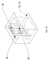
- the walls 7 are at least partially bricked up from wall elements, wherein the wall elements have channel-shaped cavities 18 and extending in the same direction supply channels 35 for heat transfer medium.
- one or more channel-shaped cavities 29 of larger diameter can be provided, which is for receiving a stabilizing resp. serve as a mounting serving cooled and preferably provided with a thermal insulation tube.
- a stabilizing resp. serve as a mounting serving cooled and preferably provided with a thermal insulation tube.
- thermal insulation for example between the inner wall of the channel-shaped cavity 29 and the cooled tube introduced a heat-insulating casting material.
- the feed / flow of the furnace 2 by the recycled from the superheater 9 heat transfer medium takes place in order to keep the pressure losses low or low, if possible parallel.
- a serial flow, i. meandering guidance of the heat transfer medium in the walls is also possible, but are associated with such a leadership of the heat transfer medium and at the desired high speed of preferably more than 60m / sec high pressure losses, which are undesirable.
Landscapes
- Engineering & Computer Science (AREA)
- Mechanical Engineering (AREA)
- General Engineering & Computer Science (AREA)
- Chemical & Material Sciences (AREA)
- Combustion & Propulsion (AREA)
- Life Sciences & Earth Sciences (AREA)
- Sustainable Development (AREA)
- Sustainable Energy (AREA)
- Physics & Mathematics (AREA)
- Thermal Sciences (AREA)
- Engine Equipment That Uses Special Cycles (AREA)
- Waste-Gas Treatment And Other Accessory Devices For Furnaces (AREA)
- Heat Treatments In General, Especially Conveying And Cooling (AREA)
Priority Applications (3)
| Application Number | Priority Date | Filing Date | Title |
|---|---|---|---|
| SI200831076T SI2011972T1 (sl) | 2007-07-03 | 2008-07-02 | Postrojenje, postopek in naprava za pridobivanje pregretega medija |
| PL08011891T PL2011972T3 (pl) | 2007-07-03 | 2008-07-02 | Instalacja, sposób i urządzenie do wytwarzania przegrzanego medium |
| CY20131100938T CY1114528T1 (el) | 2007-07-03 | 2013-10-24 | Εγκατασταση, μεθοδος και συσκευη για την παραγωγη ενος υπερθερμασμενου μεσου |
Applications Claiming Priority (1)
| Application Number | Priority Date | Filing Date | Title |
|---|---|---|---|
| CH10642007 | 2007-07-03 |
Publications (3)
| Publication Number | Publication Date |
|---|---|
| EP2011972A2 EP2011972A2 (de) | 2009-01-07 |
| EP2011972A3 EP2011972A3 (de) | 2009-08-05 |
| EP2011972B1 true EP2011972B1 (de) | 2013-07-31 |
Family
ID=39850726
Family Applications (1)
| Application Number | Title | Priority Date | Filing Date |
|---|---|---|---|
| EP08011891.2A Active EP2011972B1 (de) | 2007-07-03 | 2008-07-02 | Anlage, Verfahren und Vorrichtung zur Erzeugung eines überhitzten Mediums |
Country Status (8)
| Country | Link |
|---|---|
| EP (1) | EP2011972B1 (da) |
| CY (1) | CY1114528T1 (da) |
| DK (1) | DK2011972T3 (da) |
| ES (1) | ES2431864T3 (da) |
| HR (1) | HRP20131000T1 (da) |
| PL (1) | PL2011972T3 (da) |
| PT (1) | PT2011972E (da) |
| SI (1) | SI2011972T1 (da) |
Families Citing this family (4)
| Publication number | Priority date | Publication date | Assignee | Title |
|---|---|---|---|---|
| WO2013064169A1 (en) * | 2011-10-31 | 2013-05-10 | Ahmad Reza Shirazi | Replacing water as cooling medium with helium in major and minor industries and substitution of conventional cooling systems with cryogenic process to cool the cooling medium (helium) |
| EP3193082B1 (de) * | 2016-01-12 | 2018-08-29 | Hitachi Zosen Inova AG | Verfahren und vorrichtung zur erzeugung von überhitztem dampf mittels der im kessel einer verbrennungsanlage erzeugten wärme |
| DE102017010984B4 (de) * | 2017-11-28 | 2020-08-13 | Nippon Steel & Sumikin Engineering Co., Ltd. | Anlage zur Energieerzeugung bei der konventionellen Abfallverbrennung und Verfahren |
| JP2024115023A (ja) * | 2023-02-14 | 2024-08-26 | 荏原環境プラント株式会社 | 廃棄物燃焼発電装置、および廃棄物燃焼発電方法 |
Citations (2)
| Publication number | Priority date | Publication date | Assignee | Title |
|---|---|---|---|---|
| WO1986003824A1 (fr) * | 1984-12-17 | 1986-07-03 | Electricite De France | Paroi de foyer comportant des buses d'alimentation moulees en deux parties complementaires |
| US4624191A (en) * | 1984-12-14 | 1986-11-25 | Coal Tech Corp. | Air cooled cyclone coal combustor for optimum operation and capture of pollutants during combustion |
Family Cites Families (8)
| Publication number | Priority date | Publication date | Assignee | Title |
|---|---|---|---|---|
| US1914140A (en) | 1930-08-20 | 1933-06-13 | Babcock & Wilcox Co | High pressure boiler |
| GB682141A (en) | 1950-04-24 | 1952-11-05 | Oerlikon Maschf | Improvements in combined steam turbine and gas turbine plants |
| DK114792D0 (da) | 1992-09-17 | 1992-09-17 | Ansaldo Volund As | Fremgangsmaade og anlaeg til opnaaelse af hoeje damptemperaturer ved forbraendig af vanskelige braendsler |
| DE69732394T2 (de) | 1996-02-29 | 2006-03-30 | Mitsubishi Heavy Industries, Ltd. | Verfahren und vorrichtung zur erzeugung von überhitztem dampf mittels wärme von abfallverbrennung |
| EP1023558A1 (en) | 1997-10-14 | 2000-08-02 | Ebara Corporation | Method and apparatus for generating electric power by combusting wastes |
| FR2836715B1 (fr) | 2002-03-04 | 2004-06-25 | Brunel Bureau Et | Chaudiere a vapeur pour la production de vapeur surchauffee |
| DE10257305A1 (de) * | 2002-12-07 | 2004-06-17 | Kümmel, Joachim, Dipl.-Ing. | Verfahren und Vorrichtung zum Überhitzen von Dampf in korrosiver Rauchgasatmosphäre |
| DE102005036792A1 (de) | 2005-08-02 | 2007-02-08 | Ecoenergy Gesellschaft Für Energie- Und Umwelttechnik Mbh | Verfahren und Vorrichtung zur Erzeugung von überhitztem Dampf |
-
2008
- 2008-07-02 ES ES08011891T patent/ES2431864T3/es active Active
- 2008-07-02 PL PL08011891T patent/PL2011972T3/pl unknown
- 2008-07-02 PT PT80118912T patent/PT2011972E/pt unknown
- 2008-07-02 SI SI200831076T patent/SI2011972T1/sl unknown
- 2008-07-02 DK DK08011891.2T patent/DK2011972T3/da active
- 2008-07-02 EP EP08011891.2A patent/EP2011972B1/de active Active
-
2013
- 2013-10-23 HR HRP20131000AT patent/HRP20131000T1/hr unknown
- 2013-10-24 CY CY20131100938T patent/CY1114528T1/el unknown
Patent Citations (2)
| Publication number | Priority date | Publication date | Assignee | Title |
|---|---|---|---|---|
| US4624191A (en) * | 1984-12-14 | 1986-11-25 | Coal Tech Corp. | Air cooled cyclone coal combustor for optimum operation and capture of pollutants during combustion |
| WO1986003824A1 (fr) * | 1984-12-17 | 1986-07-03 | Electricite De France | Paroi de foyer comportant des buses d'alimentation moulees en deux parties complementaires |
Also Published As
| Publication number | Publication date |
|---|---|
| CY1114528T1 (el) | 2016-10-05 |
| ES2431864T3 (es) | 2013-11-28 |
| DK2011972T3 (da) | 2013-11-04 |
| EP2011972A3 (de) | 2009-08-05 |
| EP2011972A2 (de) | 2009-01-07 |
| HRP20131000T1 (hr) | 2013-12-20 |
| PT2011972E (pt) | 2013-11-05 |
| SI2011972T1 (sl) | 2013-12-31 |
| PL2011972T3 (pl) | 2014-01-31 |
Similar Documents
| Publication | Publication Date | Title |
|---|---|---|
| DE69307930T2 (de) | Kombikraftwerk mit einem atmosphärisch zirkulierenden wirbelbettkessel mit einem vergaser | |
| EP0714428B1 (de) | Anlage zur thermischen abfallentsorgung sowie verfahren zum betrieb einer solchen anlage | |
| DE19829088C2 (de) | Stromerzeugung in einem Verbundkraftwerk mit einer Gas- und einer Dampfturbine | |
| WO2011000447A1 (de) | Verfahren, und vorrichtung zur warmhaltung von koksofenkammern während des stillstandes eines abhitzekessels | |
| DE3503103A1 (de) | Verfahren und vorrichtung zur waermerueckgewinnung | |
| DE102018201172A1 (de) | Verbrennungsanlage mit Restwärmenutzung | |
| DE102008064321A1 (de) | Externe Frischluftvorwärmung bei Feststofffeuerungen | |
| EP2011972B1 (de) | Anlage, Verfahren und Vorrichtung zur Erzeugung eines überhitzten Mediums | |
| EP0474894B1 (de) | Gasturbinenanordnung | |
| WO2011020767A1 (de) | Verfahren und vorrichtung zur verwertung von biomassse | |
| EP1166014A1 (de) | Fossilbeheizter durchlaufdampferzeuger | |
| EP1377649A1 (de) | Anlage und verfahren zur energiegewinnung durch pyrolyse | |
| DE102014226837A1 (de) | Variabel einsetzbares Wärmetauschersystem und Verfahren zum Betreiben eines Wärmetauschersystems | |
| EP3891435B1 (de) | Verfahren zur brüdenverwertung und brüdenverwertungssystem | |
| DE102007054467A1 (de) | Verfahren zur Brennstoffvorwärmung | |
| EP0360052A1 (de) | Pyrolysereaktor zur thermischen Abfallentsorgung | |
| DE4300192C2 (de) | Verfahren zum Betrieb von mindestens zwei miteinander verknüpften Abhitzeprozessen und Dampferzeugungsanlage zur Durchführung des Verfahrens | |
| WO2014056576A1 (de) | Vorrichtung und verfahren zur erzeugung einer mehrzahl an dampf- oder heisswasserströmen in einer koksofenbank | |
| EP3859207B1 (de) | Verbrennungsanlage mit wärmespeicher | |
| DE102011082205A1 (de) | Verfahren zum Betrieb eines regenerativ beheizten Industrieofens und regenerativ geheizter Industrieofen | |
| EP2397756A2 (de) | Feuerung für die verbrennung von feststoffen | |
| WO2024022644A1 (de) | Thermisches cracking von methan oder erdgas | |
| DE69812932T2 (de) | Verfahren und vorrichtung zur beheizung eines drehrohrofens zur vergasung und zur pyrolyse von organischen substanzen | |
| EP0654591A1 (de) | Anlage zur Gewinnung elektrischer Energie aus Brennstoffen, insbesondere aus biogenen Brennstoffen | |
| EP1959195B1 (de) | Verfahren zur Regelung der Temperatur von Rauchgas |
Legal Events
| Date | Code | Title | Description |
|---|---|---|---|
| PUAI | Public reference made under article 153(3) epc to a published international application that has entered the european phase |
Free format text: ORIGINAL CODE: 0009012 |
|
| AK | Designated contracting states |
Kind code of ref document: A2 Designated state(s): AT BE BG CH CY CZ DE DK EE ES FI FR GB GR HR HU IE IS IT LI LT LU LV MC MT NL NO PL PT RO SE SI SK TR |
|
| AX | Request for extension of the european patent |
Extension state: AL BA MK RS |
|
| PUAL | Search report despatched |
Free format text: ORIGINAL CODE: 0009013 |
|
| AK | Designated contracting states |
Kind code of ref document: A3 Designated state(s): AT BE BG CH CY CZ DE DK EE ES FI FR GB GR HR HU IE IS IT LI LT LU LV MC MT NL NO PL PT RO SE SI SK TR |
|
| AX | Request for extension of the european patent |
Extension state: AL BA MK RS |
|
| 17P | Request for examination filed |
Effective date: 20100203 |
|
| 17Q | First examination report despatched |
Effective date: 20100304 |
|
| AKX | Designation fees paid |
Designated state(s): AT BE BG CH CY CZ DE DK EE ES FI FR GB GR HR HU IE IS IT LI LT LU LV MC MT NL NO PL PT RO SE SI SK TR |
|
| RAP1 | Party data changed (applicant data changed or rights of an application transferred) |
Owner name: ANDREOLI BRUNO, APS BERATUNG Owner name: CLM TECHNOLOGIE AG |
|
| REG | Reference to a national code |
Ref country code: DE Ref legal event code: R079 Ref document number: 502008010392 Country of ref document: DE Free format text: PREVIOUS MAIN CLASS: F01K0003200000 Ipc: F23G0005460000 |
|
| RIC1 | Information provided on ipc code assigned before grant |
Ipc: F22B 1/18 20060101ALI20121207BHEP Ipc: F23M 5/08 20060101ALI20121207BHEP Ipc: F23G 5/46 20060101AFI20121207BHEP |
|
| GRAP | Despatch of communication of intention to grant a patent |
Free format text: ORIGINAL CODE: EPIDOSNIGR1 |
|
| GRAS | Grant fee paid |
Free format text: ORIGINAL CODE: EPIDOSNIGR3 |
|
| GRAA | (expected) grant |
Free format text: ORIGINAL CODE: 0009210 |
|
| AK | Designated contracting states |
Kind code of ref document: B1 Designated state(s): AT BE BG CH CY CZ DE DK EE ES FI FR GB GR HR HU IE IS IT LI LT LU LV MC MT NL NO PL PT RO SE SI SK TR |
|
| REG | Reference to a national code |
Ref country code: CH Ref legal event code: NV Representative=s name: E. BLUM AND CO. AG PATENT- UND MARKENANWAELTE , CH Ref country code: GB Ref legal event code: FG4D Free format text: NOT ENGLISH Ref country code: CH Ref legal event code: EP |
|
| REG | Reference to a national code |
Ref country code: AT Ref legal event code: REF Ref document number: 624880 Country of ref document: AT Kind code of ref document: T Effective date: 20130815 |
|
| REG | Reference to a national code |
Ref country code: IE Ref legal event code: FG4D Free format text: LANGUAGE OF EP DOCUMENT: GERMAN |
|
| REG | Reference to a national code |
Ref country code: DE Ref legal event code: R096 Ref document number: 502008010392 Country of ref document: DE Effective date: 20130926 |
|
| REG | Reference to a national code |
Ref country code: RO Ref legal event code: EPE |
|
| REG | Reference to a national code |
Ref country code: SE Ref legal event code: TRGR |
|
| REG | Reference to a national code |
Ref country code: HR Ref legal event code: TUEP Ref document number: P20131000 Country of ref document: HR |
|
| REG | Reference to a national code |
Ref country code: DK Ref legal event code: T3 |
|
| REG | Reference to a national code |
Ref country code: PT Ref legal event code: SC4A Free format text: AVAILABILITY OF NATIONAL TRANSLATION Effective date: 20131028 |
|
| REG | Reference to a national code |
Ref country code: NL Ref legal event code: T3 |
|
| REG | Reference to a national code |
Ref country code: NO Ref legal event code: T2 Effective date: 20130731 Ref country code: EE Ref legal event code: FG4A Ref document number: E008578 Country of ref document: EE Effective date: 20131031 |
|
| REG | Reference to a national code |
Ref country code: HR Ref legal event code: T1PR Ref document number: P20131000 Country of ref document: HR |
|
| REG | Reference to a national code |
Ref country code: SK Ref legal event code: T3 Ref document number: E 15065 Country of ref document: SK |
|
| REG | Reference to a national code |
Ref country code: GR Ref legal event code: EP Ref document number: 20130402214 Country of ref document: GR Effective date: 20131118 |
|
| PG25 | Lapsed in a contracting state [announced via postgrant information from national office to epo] |
Ref country code: CY Free format text: LAPSE BECAUSE OF FAILURE TO SUBMIT A TRANSLATION OF THE DESCRIPTION OR TO PAY THE FEE WITHIN THE PRESCRIBED TIME-LIMIT Effective date: 20130619 |
|
| REG | Reference to a national code |
Ref country code: PL Ref legal event code: T3 |
|
| REG | Reference to a national code |
Ref country code: HU Ref legal event code: AG4A |
|
| PG25 | Lapsed in a contracting state [announced via postgrant information from national office to epo] |
Ref country code: CY Free format text: LAPSE BECAUSE OF FAILURE TO SUBMIT A TRANSLATION OF THE DESCRIPTION OR TO PAY THE FEE WITHIN THE PRESCRIBED TIME-LIMIT Effective date: 20130731 |
|
| PLBE | No opposition filed within time limit |
Free format text: ORIGINAL CODE: 0009261 |
|
| STAA | Information on the status of an ep patent application or granted ep patent |
Free format text: STATUS: NO OPPOSITION FILED WITHIN TIME LIMIT |
|
| REG | Reference to a national code |
Ref country code: HR Ref legal event code: ODRP Ref document number: P20131000 Country of ref document: HR Payment date: 20140624 Year of fee payment: 7 |
|
| 26N | No opposition filed |
Effective date: 20140502 |
|
| PGFP | Annual fee paid to national office [announced via postgrant information from national office to epo] |
Ref country code: LT Payment date: 20140620 Year of fee payment: 7 |
|
| REG | Reference to a national code |
Ref country code: DE Ref legal event code: R097 Ref document number: 502008010392 Country of ref document: DE Effective date: 20140502 |
|
| PGFP | Annual fee paid to national office [announced via postgrant information from national office to epo] |
Ref country code: RO Payment date: 20140623 Year of fee payment: 7 Ref country code: IS Payment date: 20140618 Year of fee payment: 7 Ref country code: LU Payment date: 20140722 Year of fee payment: 7 |
|
| PGFP | Annual fee paid to national office [announced via postgrant information from national office to epo] |
Ref country code: HR Payment date: 20140624 Year of fee payment: 7 |
|
| PGFP | Annual fee paid to national office [announced via postgrant information from national office to epo] |
Ref country code: NO Payment date: 20140714 Year of fee payment: 7 Ref country code: GR Payment date: 20140717 Year of fee payment: 7 Ref country code: IE Payment date: 20140724 Year of fee payment: 7 Ref country code: MC Payment date: 20140714 Year of fee payment: 7 Ref country code: BG Payment date: 20140711 Year of fee payment: 7 Ref country code: FI Payment date: 20140711 Year of fee payment: 7 Ref country code: EE Payment date: 20140714 Year of fee payment: 7 |
|
| PGFP | Annual fee paid to national office [announced via postgrant information from national office to epo] |
Ref country code: LV Payment date: 20140711 Year of fee payment: 7 Ref country code: SK Payment date: 20140701 Year of fee payment: 7 Ref country code: HU Payment date: 20140721 Year of fee payment: 7 Ref country code: SI Payment date: 20140630 Year of fee payment: 7 |
|
| PGFP | Annual fee paid to national office [announced via postgrant information from national office to epo] |
Ref country code: PT Payment date: 20131028 Year of fee payment: 7 |
|
| PGFP | Annual fee paid to national office [announced via postgrant information from national office to epo] |
Ref country code: CY Payment date: 20140623 Year of fee payment: 7 |
|
| REG | Reference to a national code |
Ref country code: CH Ref legal event code: PUE Owner name: HITACHI ZOSEN INOVA AG, CH Free format text: FORMER OWNER: CLM TECHNOLOGIE AG, CH Ref country code: CH Ref legal event code: NV Representative=s name: PATENTANWAELTE SCHAAD, BALASS, MENZL AND PARTN, CH |
|
| REG | Reference to a national code |
Ref country code: DE Ref legal event code: R082 Ref document number: 502008010392 Country of ref document: DE Representative=s name: LEIFERT & STEFFAN PATENTANWAELTE, DE |
|
| REG | Reference to a national code |
Ref country code: GB Ref legal event code: 732E Free format text: REGISTERED BETWEEN 20150416 AND 20150422 |
|
| REG | Reference to a national code |
Ref country code: DE Ref legal event code: R082 Ref document number: 502008010392 Country of ref document: DE Representative=s name: LEIFERT & STEFFAN PATENTANWAELTE, DE Effective date: 20150508 Ref country code: DE Ref legal event code: R081 Ref document number: 502008010392 Country of ref document: DE Owner name: HITACHI ZOSEN INOVA AG, CH Free format text: FORMER OWNERS: ANDREOLI BRUNO, APS BERATUNG, UERIKON, CH; CLM TECHNOLOGIE AG, ZUERICH, CH Effective date: 20150508 Ref country code: DE Ref legal event code: R081 Ref document number: 502008010392 Country of ref document: DE Owner name: HITACHI ZOSEN INOVA AG, CH Free format text: FORMER OWNER: ANDREOLI BRUNO, APS BERATUNG, CLM TECHNOLOGIE AG, , CH Effective date: 20150508 |
|
| REG | Reference to a national code |
Ref country code: FR Ref legal event code: PLFP Year of fee payment: 8 |
|
| REG | Reference to a national code |
Ref country code: ES Ref legal event code: PC2A Owner name: ANDREOLI BRUNO, APS BERATUNG Effective date: 20150820 |
|
| REG | Reference to a national code |
Ref country code: FR Ref legal event code: TP Owner name: HITACHI ZOSEN INOVA AG, CH Effective date: 20151117 |
|
| REG | Reference to a national code |
Ref country code: PT Ref legal event code: MM4A Free format text: LAPSE DUE TO NON-PAYMENT OF FEES Effective date: 20160104 |
|
| REG | Reference to a national code |
Ref country code: LT Ref legal event code: MM4D Effective date: 20150702 |
|
| REG | Reference to a national code |
Ref country code: HR Ref legal event code: PBON Ref document number: P20131000 Country of ref document: HR Effective date: 20150702 |
|
| PG25 | Lapsed in a contracting state [announced via postgrant information from national office to epo] |
Ref country code: MC Free format text: LAPSE BECAUSE OF NON-PAYMENT OF DUE FEES Effective date: 20150731 |
|
| REG | Reference to a national code |
Ref country code: NO Ref legal event code: MMEP |
|
| REG | Reference to a national code |
Ref country code: SK Ref legal event code: MM4A Ref document number: E 15065 Country of ref document: SK Effective date: 20150702 |
|
| REG | Reference to a national code |
Ref country code: EE Ref legal event code: MM4A Ref document number: E008578 Country of ref document: EE Effective date: 20150731 |
|
| PG25 | Lapsed in a contracting state [announced via postgrant information from national office to epo] |
Ref country code: LU Free format text: LAPSE BECAUSE OF NON-PAYMENT OF DUE FEES Effective date: 20150702 |
|
| REG | Reference to a national code |
Ref country code: SI Ref legal event code: KO00 Effective date: 20160222 |
|
| REG | Reference to a national code |
Ref country code: IE Ref legal event code: MM4A |
|
| PG25 | Lapsed in a contracting state [announced via postgrant information from national office to epo] |
Ref country code: EE Free format text: LAPSE BECAUSE OF NON-PAYMENT OF DUE FEES Effective date: 20150731 Ref country code: NO Free format text: LAPSE BECAUSE OF NON-PAYMENT OF DUE FEES Effective date: 20150731 Ref country code: IS Free format text: LAPSE BECAUSE OF FAILURE TO SUBMIT A TRANSLATION OF THE DESCRIPTION OR TO PAY THE FEE WITHIN THE PRESCRIBED TIME-LIMIT Effective date: 20160201 Ref country code: SK Free format text: LAPSE BECAUSE OF NON-PAYMENT OF DUE FEES Effective date: 20150702 Ref country code: HR Free format text: LAPSE BECAUSE OF NON-PAYMENT OF DUE FEES Effective date: 20150703 Ref country code: BG Free format text: LAPSE BECAUSE OF NON-PAYMENT OF DUE FEES Effective date: 20160331 Ref country code: LT Free format text: LAPSE BECAUSE OF NON-PAYMENT OF DUE FEES Effective date: 20150702 Ref country code: CY Free format text: LAPSE BECAUSE OF FAILURE TO SUBMIT A TRANSLATION OF THE DESCRIPTION OR TO PAY THE FEE WITHIN THE PRESCRIBED TIME-LIMIT Effective date: 20150702 |
|
| REG | Reference to a national code |
Ref country code: AT Ref legal event code: PC Ref document number: 624880 Country of ref document: AT Kind code of ref document: T Owner name: HITACHI ZOSEN, CH Effective date: 20160414 |
|
| PG25 | Lapsed in a contracting state [announced via postgrant information from national office to epo] |
Ref country code: LV Free format text: LAPSE BECAUSE OF NON-PAYMENT OF DUE FEES Effective date: 20150702 Ref country code: HU Free format text: LAPSE BECAUSE OF NON-PAYMENT OF DUE FEES Effective date: 20150703 Ref country code: SI Free format text: LAPSE BECAUSE OF NON-PAYMENT OF DUE FEES Effective date: 20150703 Ref country code: FI Free format text: LAPSE BECAUSE OF NON-PAYMENT OF DUE FEES Effective date: 20150702 Ref country code: PT Free format text: LAPSE BECAUSE OF NON-PAYMENT OF DUE FEES Effective date: 20160104 Ref country code: RO Free format text: LAPSE BECAUSE OF NON-PAYMENT OF DUE FEES Effective date: 20150702 Ref country code: GR Free format text: LAPSE BECAUSE OF NON-PAYMENT OF DUE FEES Effective date: 20160202 |
|
| REG | Reference to a national code |
Ref country code: GR Ref legal event code: ML Ref document number: 20130402214 Country of ref document: GR Effective date: 20160202 |
|
| PG25 | Lapsed in a contracting state [announced via postgrant information from national office to epo] |
Ref country code: MT Free format text: LAPSE BECAUSE OF FAILURE TO SUBMIT A TRANSLATION OF THE DESCRIPTION OR TO PAY THE FEE WITHIN THE PRESCRIBED TIME-LIMIT Effective date: 20130731 |
|
| REG | Reference to a national code |
Ref country code: FR Ref legal event code: PLFP Year of fee payment: 9 |
|
| PG25 | Lapsed in a contracting state [announced via postgrant information from national office to epo] |
Ref country code: IE Free format text: LAPSE BECAUSE OF NON-PAYMENT OF DUE FEES Effective date: 20150702 |
|
| REG | Reference to a national code |
Ref country code: FR Ref legal event code: PLFP Year of fee payment: 10 |
|
| REG | Reference to a national code |
Ref country code: FR Ref legal event code: PLFP Year of fee payment: 11 |
|
| PG25 | Lapsed in a contracting state [announced via postgrant information from national office to epo] |
Ref country code: MT Free format text: LAPSE BECAUSE OF FAILURE TO SUBMIT A TRANSLATION OF THE DESCRIPTION OR TO PAY THE FEE WITHIN THE PRESCRIBED TIME-LIMIT Effective date: 20150702 |
|
| PGFP | Annual fee paid to national office [announced via postgrant information from national office to epo] |
Ref country code: MT Payment date: 20140702 Year of fee payment: 7 |
|
| PGFP | Annual fee paid to national office [announced via postgrant information from national office to epo] |
Ref country code: TR Payment date: 20220629 Year of fee payment: 15 Ref country code: PL Payment date: 20220624 Year of fee payment: 15 |
|
| PGFP | Annual fee paid to national office [announced via postgrant information from national office to epo] |
Ref country code: NL Payment date: 20220720 Year of fee payment: 15 |
|
| PGFP | Annual fee paid to national office [announced via postgrant information from national office to epo] |
Ref country code: SE Payment date: 20220720 Year of fee payment: 15 Ref country code: IT Payment date: 20220726 Year of fee payment: 15 Ref country code: GB Payment date: 20220721 Year of fee payment: 15 Ref country code: ES Payment date: 20220921 Year of fee payment: 15 Ref country code: DK Payment date: 20220725 Year of fee payment: 15 Ref country code: CZ Payment date: 20220701 Year of fee payment: 15 Ref country code: AT Payment date: 20220721 Year of fee payment: 15 |
|
| PGFP | Annual fee paid to national office [announced via postgrant information from national office to epo] |
Ref country code: FR Payment date: 20220720 Year of fee payment: 15 Ref country code: BE Payment date: 20220720 Year of fee payment: 15 |
|
| PG25 | Lapsed in a contracting state [announced via postgrant information from national office to epo] |
Ref country code: CZ Free format text: LAPSE BECAUSE OF NON-PAYMENT OF DUE FEES Effective date: 20230702 |
|
| REG | Reference to a national code |
Ref country code: DK Ref legal event code: EBP Effective date: 20230731 |
|
| REG | Reference to a national code |
Ref country code: SE Ref legal event code: EUG |
|
| REG | Reference to a national code |
Ref country code: NL Ref legal event code: MM Effective date: 20230801 |
|
| REG | Reference to a national code |
Ref country code: AT Ref legal event code: MM01 Ref document number: 624880 Country of ref document: AT Kind code of ref document: T Effective date: 20230702 |
|
| REG | Reference to a national code |
Ref country code: BE Ref legal event code: MM Effective date: 20230731 |
|
| GBPC | Gb: european patent ceased through non-payment of renewal fee |
Effective date: 20230702 |
|
| PG25 | Lapsed in a contracting state [announced via postgrant information from national office to epo] |
Ref country code: NL Free format text: LAPSE BECAUSE OF NON-PAYMENT OF DUE FEES Effective date: 20230801 |
|
| PG25 | Lapsed in a contracting state [announced via postgrant information from national office to epo] |
Ref country code: AT Free format text: LAPSE BECAUSE OF NON-PAYMENT OF DUE FEES Effective date: 20230702 |
|
| PG25 | Lapsed in a contracting state [announced via postgrant information from national office to epo] |
Ref country code: NL Free format text: LAPSE BECAUSE OF NON-PAYMENT OF DUE FEES Effective date: 20230801 Ref country code: AT Free format text: LAPSE BECAUSE OF NON-PAYMENT OF DUE FEES Effective date: 20230702 Ref country code: GB Free format text: LAPSE BECAUSE OF NON-PAYMENT OF DUE FEES Effective date: 20230702 |
|
| PG25 | Lapsed in a contracting state [announced via postgrant information from national office to epo] |
Ref country code: SE Free format text: LAPSE BECAUSE OF NON-PAYMENT OF DUE FEES Effective date: 20230703 Ref country code: FR Free format text: LAPSE BECAUSE OF NON-PAYMENT OF DUE FEES Effective date: 20230731 Ref country code: BE Free format text: LAPSE BECAUSE OF NON-PAYMENT OF DUE FEES Effective date: 20230731 |
|
| PG25 | Lapsed in a contracting state [announced via postgrant information from national office to epo] |
Ref country code: DK Free format text: LAPSE BECAUSE OF NON-PAYMENT OF DUE FEES Effective date: 20230731 |
|
| PG25 | Lapsed in a contracting state [announced via postgrant information from national office to epo] |
Ref country code: IT Free format text: LAPSE BECAUSE OF NON-PAYMENT OF DUE FEES Effective date: 20230702 Ref country code: DK Free format text: LAPSE BECAUSE OF NON-PAYMENT OF DUE FEES Effective date: 20230731 |
|
| REG | Reference to a national code |
Ref country code: ES Ref legal event code: FD2A Effective date: 20240826 |
|
| PG25 | Lapsed in a contracting state [announced via postgrant information from national office to epo] |
Ref country code: ES Free format text: LAPSE BECAUSE OF NON-PAYMENT OF DUE FEES Effective date: 20230703 |
|
| PG25 | Lapsed in a contracting state [announced via postgrant information from national office to epo] |
Ref country code: ES Free format text: LAPSE BECAUSE OF NON-PAYMENT OF DUE FEES Effective date: 20230703 |
|
| PG25 | Lapsed in a contracting state [announced via postgrant information from national office to epo] |
Ref country code: PL Free format text: LAPSE BECAUSE OF NON-PAYMENT OF DUE FEES Effective date: 20230702 |
|
| PG25 | Lapsed in a contracting state [announced via postgrant information from national office to epo] |
Ref country code: PL Free format text: LAPSE BECAUSE OF NON-PAYMENT OF DUE FEES Effective date: 20230702 |
|
| REG | Reference to a national code |
Ref country code: DE Ref legal event code: R081 Ref document number: 502008010392 Country of ref document: DE Owner name: KANADEVIA INOVA AG, CH Free format text: FORMER OWNER: HITACHI ZOSEN INOVA AG, ZUERICH, CH |
|
| PGFP | Annual fee paid to national office [announced via postgrant information from national office to epo] |
Ref country code: DE Payment date: 20250722 Year of fee payment: 18 |
|
| PGFP | Annual fee paid to national office [announced via postgrant information from national office to epo] |
Ref country code: CH Payment date: 20250801 Year of fee payment: 18 |