EP2011952A2 - Separator for a carriage of a darkening device and darkening device - Google Patents
Separator for a carriage of a darkening device and darkening device Download PDFInfo
- Publication number
- EP2011952A2 EP2011952A2 EP08104616A EP08104616A EP2011952A2 EP 2011952 A2 EP2011952 A2 EP 2011952A2 EP 08104616 A EP08104616 A EP 08104616A EP 08104616 A EP08104616 A EP 08104616A EP 2011952 A2 EP2011952 A2 EP 2011952A2
- Authority
- EP
- European Patent Office
- Prior art keywords
- carriage
- spacer
- coupling piece
- ramp
- hook
- Prior art date
- Legal status (The legal status is an assumption and is not a legal conclusion. Google has not performed a legal analysis and makes no representation as to the accuracy of the status listed.)
- Withdrawn
Links
Images


Classifications
-
- E—FIXED CONSTRUCTIONS
- E06—DOORS, WINDOWS, SHUTTERS, OR ROLLER BLINDS IN GENERAL; LADDERS
- E06B—FIXED OR MOVABLE CLOSURES FOR OPENINGS IN BUILDINGS, VEHICLES, FENCES OR LIKE ENCLOSURES IN GENERAL, e.g. DOORS, WINDOWS, BLINDS, GATES
- E06B9/00—Screening or protective devices for wall or similar openings, with or without operating or securing mechanisms; Closures of similar construction
- E06B9/24—Screens or other constructions affording protection against light, especially against sunshine; Similar screens for privacy or appearance; Slat blinds
- E06B9/26—Lamellar or like blinds, e.g. venetian blinds
- E06B9/36—Lamellar or like blinds, e.g. venetian blinds with vertical lamellae ; Supporting rails therefor
- E06B9/362—Travellers; Lamellae suspension stems
- E06B9/365—Distance pieces therefor
Definitions
- the invention relates to a spacer for a carriage of a shading system, in particular vertical blind, with a coupling piece for detachable coupling with the carriage. Furthermore, the invention relates to a shading system, in particular vertical blinds, with carriages movably guided in a mounting rail, of which the carriage closest to one end of the mounting rail - end carriage - is held by means of a spacer to a predetermined position.
- Such a spacer or such shading system is from the EP 1 111 184 B1 known.
- the invention is primarily concerned with vertical blinds, but is analogous to other shading systems, such as horizontal blinds, in which the shading curtain is held on movably guided in a support rail carriage used.
- the mounting rail is mounted horizontally in the window reveal or on a building wall or ceiling.
- the actual curtain namely individual Vertical slats held on the support rail, wherein the curtain can be moved up and pulled in at transverse to the window plane oriented vertical slats by means of a at a foremost carriage, generally referred to as a train carriage attached cable.
- This train carriage successively draws on trailing carriages via spacers.
- a swivel gear is arranged in the carriage, which pivots about a pivot shaft, the vertical slats about its vertical longitudinal axis.
- vertical slats When tilted in a plane parallel to the window plane vertical slats should in particular arranged within a window reveal vertical blinds of the distance of one end of the support rail nearest carriage, generally referred to as Endwagen correspond to approximately half the slat width, so that the slat does not hit the inside against the window reveal.
- the invention is based on the problem of proposing a spacer and a shading system with such a spacer, which is as simple as possible in its structural design and yet a complete process of the disk set against the end of the support rail and a simple complete release of the end of the carriage allows.
- the spacer according to the invention is characterized in that the carriage is designed as a final carriage and cooperates with an actuating means which disengages the coupling piece in a process of the carriage in one direction and brings in process of the carriage in the opposite direction again ,
- the shading system is to solve this problem characterized in that the spacer has a cooperating with the end carriage actuator which brings the spacer in the process of the final carriage in a direction out of engagement and in the method of the end car in the opposite direction again engaged.
- the end car When the curtain is closed, the end car is held by the spacer at the predetermined position. Now, if the lamellae are moved together to form a package, the other carriage push the endcar towards the end of the mounting rail. In this case, the spacer is disengaged by the actuator and all carriages, including the end car, can be moved in the direction of the end of the support rail. In this case, the other carriages can be moved beyond the position defined by the spacer for the end car in itself position. Due to the actuator of the disengagement of the coupling piece and these are initially not held by the coupling piece in the process in the opposite direction. Only when the end car is held in its predetermined position when pulling the curtain, the coupling piece comes back into engagement with the end car and keeps it in the predetermined position.
- the coupling piece is designed as a hook.
- the hook itself prevents the carriage from being moved beyond the predetermined position in one direction and thus constitutes a stop for the carriage while the hook releases the carriage in the opposite direction.
- the spacer be formed so that this function can be disabled.
- a locking means on the spacer which completely locks the end carriage together with the hook.
- the hook thus forms a stop for the one direction of travel of the carriage (closing direction of the curtain), while the locking means is a stop in the opposite direction (opening direction of the curtain).
- the end car is firmly positioned between the hook and the locking means.
- this locking means is pivotally mounted on the spacer. By simply swiveling it can be put into or out of function.
- Fig. 1 shows a Laufzug, the sake of simplicity, here only four carriages 20, 21, 22 and 23 consists.
- This carriage 20..23 are movably guided in a support rail, not shown here in the longitudinal direction of the support rail.
- This support rail is closed by means of two end caps 24, 25 on the front side.
- left end cap 24 has only one deflection means for a circulating pull cord 26 and a pivot bearing for a turning shaft 27.
- the opposite end cap 25, which is also referred to in part as a functional cap, has deflection means for the pull cord 26, by means of which the pull cord 26 is guided out of the mounting rail down so that it can be detected by the operator.
- end cap 25 carries a circumferential chain 28, which cooperates with a pinion within the end cap 25 and by means of which the turning shaft 27 can be rotated about its longitudinal axis. This rotational movement is converted via known transmission within the carriage 20..23 in a pivoting movement of the hanging on the carriage 20..23 vertical slats.
- the in Fig. 1 the leftmost carriage 20 serves as a train carriage.
- a run 29 of the pull cord 26 is fixedly connected to the carriage 20, while the other strand 30 is slidably passed through the carriage 20.
- both strands 29, 30 slidably passed through all other carriages 21, 22, 23.
- By pulling the strand 29 of the carriage 20 is moved in the direction of the end cap 25 and thereby opened the curtain.
- the carriage 20 is moved in the direction of the other end cap 24, thereby closing the curtain.
- Distance strips 31 thereby pull the other carriages 21, 22, 23 in a conventional manner. In doing so, the in Fig.
- the spacer 32 is resiliently mounted on its associated end cap, here on the end cap 25.
- the spacer 32 is fixedly attached to the end cap 25, that by bending its end cap 25 facing the end 33, the resilient connection is made.
- the spacer 32 can thereby be pivoted in a plane parallel to the window plane or within the Behangbene.
- the end 33 opposite end of the spacer 32 has a coupling piece, namely a hook 34, on.
- the hook 34 the end car 23 can hook into the spacer 32, so that the end carriage 23 in the illustrations according to Fig. 11 to 13 not further to the right, so away from the associated end cap 25, can be moved.
- the end carriage 23 is held at a maximum distance to the end cap 25, which corresponds to half the slat width.
- the spacer 32 further comprises an upright web 35, which in the present case is arranged laterally on the spacer 32 (see, for example Fig. 2 and 5 ).
- This upright web 35 has, at its end facing the hook 34, a ramp 36 rising away from the hook 34.
- the length of this ramp 36 seen in the longitudinal direction of the spacer 32 and thus their slope is maximally as long as the width, also seen in the longitudinal direction of the spacer 32, the end car 23 and the other carriage 20, 21, 22. The reason for this from the following description even more apparent.
- the upright web 35 further has a second ramp 37 which drops evenly towards the end cap 25, said second ramp 37 engaging with the first, the hook 34 facing ramp 36 is flush, so that a common edge 38 is formed.
- a web 39 presses the hook 34 in the illustration according to FIG Fig. 11 to 13 down by sliding along the ramp 36.
- the hook 34 is disengaged from the end carriage 23 and also the following carriages 21, 22 can be pushed onto the spacer 32, without the hook 34 comes into engagement with these carriages 21, 22, so that all carriages 20..23 over the hook 34 can be pushed together to form a package.
- the webs 39 of all carriage 20..23 hold the spacer 32 namely by means of the gently sloping ramp 37 in the depressed down position, which actually corresponds to an upwardly pressed position.
- the axial length of the hook 34 facing the ramp 36 may not exceed the width of a carriage 20..23.
- the axial length of this ramp 36 may correspond to a maximum of the clearance between the two webs 39 one and the same carriage 20..23, as he otherwise when pulling the blind behind a freely movable carriage 20..22 and not only in the end car 23 would snap.
- the slope of this ramp 36 should be chosen so flat that as little force must be used to bring the hook 34 out of engagement. With these dimensions, so subsequent carriage 20..22 can postpone with the spacer 32.
- the following carriage 20..22 as in particular the example of the carriage 21 in Fig.
- the spacer 32 is associated with a locking means 40, which is designed so that it either the end car 23 completely blocked or in the sense of the basis of Fig. 11 to 13 function described.
- the latter position of the locking means 40 is in the Fig. 11 to 13 shown.
- the locking means 40 is pivotally supported on the spacer 32. It has for this purpose a nipple 41, which engages in a complementary bore 42 in the spacer 32 in the sense of a hinge connection.
- a nipple 41 which engages in a complementary bore 42 in the spacer 32 in the sense of a hinge connection.
- a kinematic reversal of the nipple 41 and the spacer 32 and the bore 42 are assigned to the locking means 40.
- the locking means 40 At its opposite end of the nipple 41, the locking means 40 an upright, directed away from the spacer 32 locking web 43, which at the in the Fig. 11 to 13 shown position, which is hereinafter referred to as rearwardly pivoted position, is arranged so that it does not hinder the displacement of the end car 23 within the predetermined range.
- This position of the locking means 40 is also in Fig. 10 shown.
- the locking means 40 to the nipple 41 by 180 ° in the in Fig. 8 swung position shown.
- Fig. 9 shows for clarity an intermediate position of the locking means 40.
- the end carriage 23 should be completely detachable from the spacer 32. This is done in a simple manner in that the spacer 32 by the operator, possibly with the aid of a suitable tool, is pivoted so that the hook 34 is disengaged from the web 39 of the endcar 23. Specifically, this is a thickening 45 provided laterally on the spacer 32. This thickening 45 is located in an area which is always freely accessible to the operator through the mounting rail. Aids are not required.
- the end car can now be moved away from the end cap 25 away.
- the disk pack can be moved freely on the mounting rail, so that the window can be cleaned in a comfortable way.
Abstract
Description
Die Erfindung betrifft einen Abstandhalter für einen Laufwagen einer Verschattungsanlage, insbesondere Vertikaljalousie, mit einem Kuppelstück zum lösbaren Kuppeln mit dem Laufwagen. Des weiteren betrifft die Erfindung eine Verschattungsanlage, insbesondere Vertikaljalousie, mit in einer Tragschiene verfahrbar geführten Laufwagen, von denen der einem Ende der Tragschiene nächstliegende Laufwagen - Endwagen - mittels eines Abstandhalters auf eine vorbestimmte Position gehalten wird.The invention relates to a spacer for a carriage of a shading system, in particular vertical blind, with a coupling piece for detachable coupling with the carriage. Furthermore, the invention relates to a shading system, in particular vertical blinds, with carriages movably guided in a mounting rail, of which the carriage closest to one end of the mounting rail - end carriage - is held by means of a spacer to a predetermined position.
Ein solcher Abstandhalter bzw. eine solche Verschattungsanlage ist aus der
Die Erfindung befaßt sich vornehmlich mit Vertikaljalousien, ist analog aber auch bei anderen Verschattungsanlagen, wie beispielsweise Horizontaljalousien, bei denen der schattenspendende Behang an verfahrbar in einer Tragschiene geführten Laufwagen gehalten ist, einsetzbar. Bei Vertikaljalousien ist die Tragschiene horizontal verlaufend in der Fensterlaibung oder an einer Gebäudewand oder -decke befestigt. Mittels Laufwagen wird der eigentliche Behang, nämlich einzelne Vertikallamellen, an der Tragschiene gehalten, wobei der Behang bei quer zur Fensterebene orientierten Vertikallamellen mittels eines an einem vordersten Laufwagen, im allgemeinen als Zugwagen bezeichnet, angebrachten Seilzug auf-und zugezogen werden kann. Dieser Zugwagen zieht über Distanzhalter die nachlaufenden Laufwagen sukzessive nach. Ferner ist in dem Laufwagen ein Schwenkgetriebe angeordnet, welches über eine Schwenkwelle die Vertikallamellen um ihre vertikale Längsachse schwenkt. Bei in einer zur Fensterebene parallelen Ebene geschwenkten Vertikallamellen sollte insbesondere bei innerhalb einer Fensterlaibung angeordneten Vertikaljalousien der Abstand des einem Ende der Tragschiene nächstliegenden Laufwagens, allgemein als Endwagen bezeichnet, etwa der halben Lamellenbreite entsprechen, damit die Lamelle nicht innen gegen die Fensterlaibung stößt. Werden die Lamellen dann aber in eine zur Fensterebene quer gerichtete Richtung geschwenkt und die Vertikaljalousie geöffnet, indem die Laufwagen zum Paket gegen den Endwagen gezogen werden, verbleibt zwischen der Fensterlaibung und der an dem Endwagen hängenden Vertikallamelle ein optisch unschöner Spalt von etwa der halben Lamellenbreite.The invention is primarily concerned with vertical blinds, but is analogous to other shading systems, such as horizontal blinds, in which the shading curtain is held on movably guided in a support rail carriage used. For vertical blinds, the mounting rail is mounted horizontally in the window reveal or on a building wall or ceiling. By means of carriages, the actual curtain, namely individual Vertical slats held on the support rail, wherein the curtain can be moved up and pulled in at transverse to the window plane oriented vertical slats by means of a at a foremost carriage, generally referred to as a train carriage attached cable. This train carriage successively draws on trailing carriages via spacers. Further, a swivel gear is arranged in the carriage, which pivots about a pivot shaft, the vertical slats about its vertical longitudinal axis. When tilted in a plane parallel to the window plane vertical slats should in particular arranged within a window reveal vertical blinds of the distance of one end of the support rail nearest carriage, generally referred to as Endwagen correspond to approximately half the slat width, so that the slat does not hit the inside against the window reveal. However, if the slats are then pivoted in a direction transverse to the window plane direction and the vertical blind opened by the carriages are pulled to the package against the end car, remains between the window reveal and hanging on the end car vertical slat an optically unattractive gap of about half the slat width.
Zur Vermeidung dieses Nachteils ist beispielsweise durch die
Aus der
Hiervon ausgehend liegt der Erfindung das Problem zugrunde, einen Abstandhalter und eine Verschattungsanlage mit einem solchen Abstandhalter vorzuschlagen, der in seinem konstruktiven Aufbau möglichst einfach ist und dennoch ein vollständiges Verfahren des Lamellenpakets gegen das Ende der Tragschiene und ein einfaches vollständiges Lösen des Endwagens von dem Abstandhalter ermöglicht.Proceeding from this, the invention is based on the problem of proposing a spacer and a shading system with such a spacer, which is as simple as possible in its structural design and yet a complete process of the disk set against the end of the support rail and a simple complete release of the end of the carriage allows.
Zur Lösung dieses Problems ist der erfindungsgemäße Abstandhalter dadurch gekennzeichnet, dass der Laufwagen als ein Endwagen ausgebildet ist und mit einem Betätigungsmittel zusammenwirkt, welches das Kuppelstück bei Verfahren des Laufwagens in eine Richtung außer Eingriff bringt und bei Verfahren des Laufwagens in die Gegenrichtung wieder in Eingriff bringt. Die Verschattungsanlage ist zur Lösung dieses Problems dadurch gekennzeichnet, daß der Abstandhalter ein mit dem Endwagen zusammenwirkendes Betätigungsorgan aufweist, welches den Abstandhalter bei Verfahren des Endwagens in eine Richtung außer Eingriff und bei Verfahren des Endwagens in die Gegenrichtung wieder in Eingriff bringt.To solve this problem, the spacer according to the invention is characterized in that the carriage is designed as a final carriage and cooperates with an actuating means which disengages the coupling piece in a process of the carriage in one direction and brings in process of the carriage in the opposite direction again , The shading system is to solve this problem characterized in that the spacer has a cooperating with the end carriage actuator which brings the spacer in the process of the final carriage in a direction out of engagement and in the method of the end car in the opposite direction again engaged.
Bei geschlossenem Behang wird der Endwagen durch den Abstandhalter auf der vorbestimmten Position gehalten. Werden nun die Lamellen zu einem Paket zusammengefahren, stoßen die übrigen Laufwagen den Endwagen in Richtung auf das Ende der Tragschiene. Dabei gelangt der Abstandhalter durch das Betätigungsorgan außer Eingriff und sämtliche Laufwagen, einschließlich des Endwagens, können in Richtung auf das Ende der Tragschiene verfahren werden. Dabei können auch die übrigen Laufwagen über die durch den Abstandhalter für den Endwagen an sich definierte Position hinaus verfahren werden. Aufgrund des Betätigungsorgans des Außereingriffbringens des Kuppelstücks werden auch diese beim Verfahren in Gegenrichtung zunächst nicht durch das Kuppelstück gehalten. Erst wenn der Endwagen beim Zuziehen des Behangs in seiner vorbestimmten Position gehalten wird, gelangt das Kuppelstück wieder in Eingriff mit dem Endwagen und hält ihn in der vorbestimmten Position.When the curtain is closed, the end car is held by the spacer at the predetermined position. Now, if the lamellae are moved together to form a package, the other carriage push the endcar towards the end of the mounting rail. In this case, the spacer is disengaged by the actuator and all carriages, including the end car, can be moved in the direction of the end of the support rail. In this case, the other carriages can be moved beyond the position defined by the spacer for the end car in itself position. Due to the actuator of the disengagement of the coupling piece and these are initially not held by the coupling piece in the process in the opposite direction. Only when the end car is held in its predetermined position when pulling the curtain, the coupling piece comes back into engagement with the end car and keeps it in the predetermined position.
Nach einer konstruktiven Ausgestaltung der Erfindung ist das Kuppelstück als Haken ausgebildet. Der Haken selbst verhindert, daß der Laufwagen in eine Richtung über die vorbestimmte Position hinaus verfahren wird und bildet demnach einen Anschlag für den Laufwagen, während der Haken den Laufwagen in Gegenrichtung freigibt.According to a structural embodiment of the invention, the coupling piece is designed as a hook. The hook itself prevents the carriage from being moved beyond the predetermined position in one direction and thus constitutes a stop for the carriage while the hook releases the carriage in the opposite direction.
Damit nun auch nachfolgende Laufwagen, die nicht Endwagen sind, über den Haken hinaus verfahren werden können, wenn der Behang geschlossen wird, muß der Haken so lange außer Eingriff gebracht werden, bis der Endwagen seine vorbestimmte Position erreicht hat. Zu diesem Zweck ist nach einer Weiterbildung der Erfindung vorgesehen, das Betätigungsorgan mit einer vom Haken weggerichteten ansteigenden Rampe auszurüsten. Durch Verschieben des Endwagens entlang der Rampe wird der Haken außer Eingriff geschwenkt. Um dabei auch sicher zu stellen, daß der Haken nicht schon einen der Laufwagen hintergreift, die noch nicht Endwagen sind, sollte in Fahrrichtung der Laufwagen gesehen, die Länge der Rampe maximal so groß sein wie die Breite des Endwagens. Ein Rückstellen des Hakens in die Kuppelstellung erfolgt vorzugsweise durch eine Federvorspannung des Abstandhalters. Hierzu kann der Abstandhalter als elastisch sich verbiegender einseitig eingespannter Balken ausgebildet sein.So now also subsequent carriage, which are not end cars, can be moved beyond the hook, when the curtain is closed, must the hook are disengaged until the end car has reached its predetermined position. For this purpose, it is provided according to a development of the invention to equip the actuator with a directed away from the hook rising ramp. By moving the endcarriage along the ramp, the hook is pivoted out of engagement. In order to make sure that the hook does not already engage behind one of the carriages, which are not yet Endwagen, the carriage should be seen in the direction of travel, the maximum length of the ramp be as large as the width of the end car. A return of the hook in the coupling position is preferably carried out by a spring bias of the spacer. For this purpose, the spacer may be formed as elastically bending single-sided clamped beam.
Nicht immer ist die vorstehend beschriebene Funktion, daß der Endwagen näher an die Endkappe herangefahren werden kann, erwünscht. Um eine universell einsetzbare Verschattungsanlage zu schaffen, ist es daher wünschenswert, daß der Abstandshalter so ausgebildet wird, daß diese Funktion außer Kraft gesetzt werden kann. Hierzu dient nach einer auch unabhängig denkbaren Weiterbildung der Erfindung ein Arretiermittel am Abstandhalter, welches den Endwagen gemeinsam mit dem Haken vollständig arretiert. Der Haken bildet somit einen Anschlag für die eine Fahrrichtung der Laufwagen (Schließrichtung des Behangs), während das Arretiermittel einen Anschlag in Gegenrichtung (Öffnungsrichtung des Behangs) darstellt. Der Endwagen ist zwischen dem Haken und dem Arretiermittel fest positioniert. Vorzugsweise ist dieses Arretiermittel schwenkbar am Abstandshalter angebracht. Durch einfaches Umschwenken kann es damit in oder außer Funktion gesetzt werden.Not always the function described above, that the end car can be moved closer to the end cap, desired. In order to provide a universally applicable shading system, it is therefore desirable that the spacer be formed so that this function can be disabled. For this purpose, according to an independently conceivable embodiment of the invention, a locking means on the spacer, which completely locks the end carriage together with the hook. The hook thus forms a stop for the one direction of travel of the carriage (closing direction of the curtain), while the locking means is a stop in the opposite direction (opening direction of the curtain). The end car is firmly positioned between the hook and the locking means. Preferably, this locking means is pivotally mounted on the spacer. By simply swiveling it can be put into or out of function.
Die Erfindung wird nachfolgend anhand eines in der Zeichnung dargestellten Ausführungsbeispiels näher erläutert. In der Zeichnung zeigen:
- Fig. 1
- einen Laufzug mit Endkappen und weiteren Funktionselementen einer Vertikaljalousie mit den Erfindungsmerkmalen in perspektivischer Draufsicht,
- Fig. 2
- den Laufzug gemäß
Fig. 1 in Unteransicht mit zum Paket gefahrenem Laufwagen, - Fig. 3
- den Laufzug gemäß
Fig. 2 im Vertikalschnitt in der Ebene III - III, - Fig. 4
- den Laufzug gemäß
Fig. 2 in perspektivischer Unteransicht, - Fig. 5
- den Laufzug gemäß
Fig. 1 bei auseinandergefahrenen Laufwagen in Unteransicht, - Fig. 6
- den Laufzug gemäß
Fig. 5 im Vertikalschnitt in der Ebene VI - VI, - Fig. 7
- den Laufzug gemäß
Fig. 5 in perspektivischer Unteransicht, - Fig. 8
- eine Endkappe mit einem Abstandhalter mit den Erfindungsmerkmalen in perspektivischer Unteransicht mit einem Arretiermittel in einer ersten Funktionsstellung,
- Fig.9
- die Endkappe gemäß
Fig. 8 mit dem Arretiermittel in einer Zwischenstellung, - Fig. 10
- die Endkappe gemäß
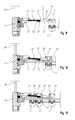
Fig. 8 mit dem Arretiermittel in einer zweiten Funktionsstellung, - Fig. 11
- eine Endkappe mit Endwagen bei geschlossenem Behang,
- Fig. 12
- die Endkappe mit Endwagen gemäß
Fig. 11 bei teilgeöffnetem Behang, - Fig. 13
- die Endkappe mit Endwagen gemäß
Fig. 11 mit weiteren Laufwagen bei weiter geöffnetem Behang (fast erreichter Paketstellung des Behangs).
- Fig. 1
- a Laufzug with end caps and other functional elements of a vertical blind with the features of the invention in a perspective plan view,
- Fig. 2
- the draft according to
Fig. 1 in bottom view with the carriage driven to the package, - Fig. 3
- the draft according to
Fig. 2 in vertical section in the plane III - III, - Fig. 4
- the draft according to
Fig. 2 in perspective bottom view, - Fig. 5
- the draft according to
Fig. 1 when the carriage is moved apart in a lower view, - Fig. 6
- the draft according to
Fig. 5 in vertical section in the plane VI - VI, - Fig. 7
- the draft according to
Fig. 5 in perspective bottom view, - Fig. 8
- an end cap with a spacer with the features of the invention in a perspective bottom view with a locking means in a first functional position,
- Figure 9
- the end cap according to
Fig. 8 with the locking means in an intermediate position, - Fig. 10
- the end cap according to
Fig. 8 with the locking means in a second functional position, - Fig. 11
- an end cap with end car with closed curtain,
- Fig. 12
- the end cap with end carriage according to
Fig. 11 with partially opened curtain, - Fig. 13
- the end cap with end carriage according to
Fig. 11 with further carriages with further open hangings (almost achieved package position of the curtain).
Der in
Der Abstandhalter 32 ist federnd an seiner zugehörigen Endkappe, vorliegend an der Endkappe 25, gelagert. Im vorliegenden Fall ist der Abstandhalter 32 derart fest an der Endkappe 25 angebracht, daß durch Biegen seines der Endkappe 25 zugewandten Endes 33 die federnde Verbindung hergestellt ist. Der Abstandhalter 32 läßt sich hierdurch in einer Ebene parallel zur Fensterebene bzw. innerhalb der Behangebene verschwenken. An seinem freien, dem Ende 33 gegenüberliegenden Ende weist der Abstandhalter 32 ein Kuppelstück, nämlich einen Haken 34, auf. Mittels des Hakens 34 läßt sich der Endwagen 23 in den Abstandhalter 32 einhaken, so daß der Endwagen 23 in den Darstellungen gemäß
Der Abstandhalter 32 weist weiterhin einen aufrechten Steg 35 auf, welcher im vorliegenden Fall seitlich am Abstandhalter 32 angeordnet ist (siehe beispielsweise
Wird nun der Endwagen 23 durch den nachfolgenden Laufwagen 22 in Richtung auf die Endkappe 25 verschoben, drückt ein Steg 39 den Haken 34 in der Darstellung gemäß der
Nicht immer ist die zuvor beschriebene Funktion, daß sich der Endwagen 23 vollständig in Richtung auf die Endkappe 25 verschieben läßt, erwünscht. Aus diesem Grund ist dem Abstandhalter 32 ein Arretiermittel 40 zugeordnet, welches so ausgebildet ist, daß es wahlweise den Endwagen 23 vollständig blockiert oder im Sinne der anhand der
An seinem dem Nippel 41 gegenüberliegenden Ende weist das Arretiermittel 40 einen aufrechten, von dem Abstandhalter 32 weg gerichteten Arretiersteg 43 auf, welcher bei der in den
Um das Behangpaket vollständig von der Fensterlaibung weg verfahren zu können, sollte der Endwagen 23 vollständig vom Abstandhalter 32 lösbar sein. Dieses geschieht auf einfache Weise dadurch, daß der Abstandhalter 32 vom Bediener, unter Umständen unter Zuhilfenahme eines geeigneten Werkzeuges, so verschwenkt wird, daß der Haken 34 außer Eingriff mit dem Steg 39 des Endwagens 23 gelangt. Konkret ist hierfür eine Verdickung 45 seitlich am Abstandhalter 32 vorgesehen. Diese Verdickung 45 befindet sich in einem Bereich, der durch die Tragschiene hindurch stets frei für den Bediener zugänglich ist. Hilfsmittel sind hierdurch nicht erforderlich.In order to be able to completely move the hanging package away from the window reveal, the
Der Endwagen kann nun von der Endkappe 25 weg verfahren werden. Das Lamellenpaket läßt sich frei an der Tragschiene verfahren, so daß das Fenster auf bequeme Weise geputzt werden kann.The end car can now be moved away from the
- 2020
- Laufwagen (Zugwagen)Carriage (train carriage)
- 2121
- Laufwagencarriage
- 2222
- Laufwagencarriage
- 2323
- Laufwagen (Endwagen)Carriage (Endcarriage)
- 2424
- Endkappeendcap
- 2525
- Endkappeendcap
- 2626
- Zugschnurdrawstring
- 2727
- Wendewelleturning shaft
- 2828
- KetteChain
- 2929
- TrumTrum
- 3030
- TrumTrum
- 3131
- Distanzstreifenspacer strips
- 3232
- Abstandhalterspacer
- 3333
- EndeThe End
- 3434
- Hakenhook
- 3535
- Stegweb
- 3636
- Ramperamp
- 3737
- Ramperamp
- 3838
- Kanteedge
- 3939
- Stegweb
- 4040
- Arretiermittellocking
- 4141
- Nippelnipple
- 4242
- Bohrungdrilling
- 4343
- Arretiersteglocking web
- 4444
- Spaltgap
Claims (14)
Applications Claiming Priority (1)
| Application Number | Priority Date | Filing Date | Title |
|---|---|---|---|
| DE102007030906A DE102007030906A1 (en) | 2007-07-03 | 2007-07-03 | Spacer for a carriage of a shading system and shading system |
Publications (2)
| Publication Number | Publication Date |
|---|---|
| EP2011952A2 true EP2011952A2 (en) | 2009-01-07 |
| EP2011952A3 EP2011952A3 (en) | 2012-08-29 |
Family
ID=39791118
Family Applications (1)
| Application Number | Title | Priority Date | Filing Date |
|---|---|---|---|
| EP08104616A Withdrawn EP2011952A3 (en) | 2007-07-03 | 2008-07-02 | Separator for a carriage of a darkening device and darkening device |
Country Status (2)
| Country | Link |
|---|---|
| EP (1) | EP2011952A3 (en) |
| DE (1) | DE102007030906A1 (en) |
Cited By (1)
| Publication number | Priority date | Publication date | Assignee | Title |
|---|---|---|---|---|
| US11746590B2 (en) | 2017-01-25 | 2023-09-05 | Hunter Douglas Inc. | Vertical cellular drape for an architectural structure |
Citations (5)
| Publication number | Priority date | Publication date | Assignee | Title |
|---|---|---|---|---|
| CH608858A5 (en) | 1976-08-04 | 1979-01-31 | Bratschi Silent Gliss | |
| DE3525590A1 (en) | 1985-07-18 | 1987-01-22 | Sunteca Sonnenschutz | Spacers for running carriages in vertical blinds |
| US4958672A (en) | 1988-01-08 | 1990-09-25 | Meyer Pieter N | Suspension system for vertical blinds |
| DE3620039C2 (en) | 1986-06-14 | 1997-12-18 | Benthin Sonnenschutz Gmbh | End car stopper for vertical blinds |
| EP1111184B1 (en) | 1999-12-14 | 2004-02-25 | Hunter Douglas Industries B.V. | Releasable end stop |
Family Cites Families (4)
| Publication number | Priority date | Publication date | Assignee | Title |
|---|---|---|---|---|
| US5351741A (en) * | 1993-06-25 | 1994-10-04 | Springs Window Fashions Division, Inc. | Vertical blind with releasable carriage latch |
| CA2224543C (en) * | 1997-12-09 | 2003-02-11 | Stores All-Teck P.T.B. Inc./All-Teck Blinds P.T.B. Inc. | Concealed-wand control for a vertical blind |
| US6957682B2 (en) * | 2003-12-11 | 2005-10-25 | Tai-Long Huang | Carrier-positioning device for a vertical blind |
| GB0601546D0 (en) * | 2006-01-26 | 2006-03-08 | Harris Parts Ltd | Carrier for a vertical louver blind |
-
2007
- 2007-07-03 DE DE102007030906A patent/DE102007030906A1/en not_active Withdrawn
-
2008
- 2008-07-02 EP EP08104616A patent/EP2011952A3/en not_active Withdrawn
Patent Citations (5)
| Publication number | Priority date | Publication date | Assignee | Title |
|---|---|---|---|---|
| CH608858A5 (en) | 1976-08-04 | 1979-01-31 | Bratschi Silent Gliss | |
| DE3525590A1 (en) | 1985-07-18 | 1987-01-22 | Sunteca Sonnenschutz | Spacers for running carriages in vertical blinds |
| DE3620039C2 (en) | 1986-06-14 | 1997-12-18 | Benthin Sonnenschutz Gmbh | End car stopper for vertical blinds |
| US4958672A (en) | 1988-01-08 | 1990-09-25 | Meyer Pieter N | Suspension system for vertical blinds |
| EP1111184B1 (en) | 1999-12-14 | 2004-02-25 | Hunter Douglas Industries B.V. | Releasable end stop |
Cited By (1)
| Publication number | Priority date | Publication date | Assignee | Title |
|---|---|---|---|---|
| US11746590B2 (en) | 2017-01-25 | 2023-09-05 | Hunter Douglas Inc. | Vertical cellular drape for an architectural structure |
Also Published As
| Publication number | Publication date |
|---|---|
| DE102007030906A1 (en) | 2009-01-15 |
| EP2011952A3 (en) | 2012-08-29 |
Similar Documents
| Publication | Publication Date | Title |
|---|---|---|
| EP1389544B1 (en) | Roller blind with coupling mechanism | |
| EP1886853B1 (en) | Window roller blind actuated by the window handle | |
| EP0382172A2 (en) | Louvered roller shutter | |
| EP1740426A1 (en) | Roller blind system for a vehicle roof | |
| EP1886854A1 (en) | Manual window roller blind with automatic retract | |
| WO2005082656A1 (en) | Motor vehicle door comprising several adjustable components | |
| DE102019213486A1 (en) | Cooking device with a specific door opening device for automatically pivoting a retractable door of the cooking device, as well as a method | |
| EP3231649B1 (en) | Shading system for a motor vehicle | |
| EP0601454A1 (en) | Roller blind for motor vehicle | |
| DE2507893C3 (en) | Window lifter for vertically subdivided motor vehicle sliding windows | |
| DE10163122B4 (en) | Roller blind for motor vehicle windows in the roof area | |
| DE102009033885A1 (en) | Vehicle roof-roller blind arrangement, has guide device with guide insert projecting into lower sliding groove and bent part between insertion parts to press bent part transverse to fabric blind and in lower sliding groove | |
| DE102008008941B4 (en) | Sun protection system with a windable curtain | |
| DE102012215433B4 (en) | Roller blind system for a vehicle interior | |
| EP3478521B1 (en) | Shading device for a window of a motor vehicle | |
| EP2011952A2 (en) | Separator for a carriage of a darkening device and darkening device | |
| DE4323993C2 (en) | Foldable or gatherable curtain | |
| DE102006004139A1 (en) | Blind system for a vehicle comprises a sliding device having a first lifting arm and a second lifting arm pivoting with the first arm about an axis | |
| DE102009034205B4 (en) | Roof sliding window with several window sashes | |
| EP3511493B1 (en) | Sliding door system | |
| DE202014004170U1 (en) | Protective blind for a window or door opening | |
| DE202007008049U1 (en) | Guide assembly of a motor vehicle window lifter | |
| EP3309318B1 (en) | Pergola awning with coupled cross bars | |
| EP1588012B1 (en) | Spacer and shading device, particularly vertical blinds or curtain, comprising said spacer | |
| DE102022203507A1 (en) | Household appliance with a retractable door and a specially designed cable pull device |
Legal Events
| Date | Code | Title | Description |
|---|---|---|---|
| PUAI | Public reference made under article 153(3) epc to a published international application that has entered the european phase |
Free format text: ORIGINAL CODE: 0009012 |
|
| AK | Designated contracting states |
Kind code of ref document: A2 Designated state(s): AT BE BG CH CY CZ DE DK EE ES FI FR GB GR HR HU IE IS IT LI LT LU LV MC MT NL NO PL PT RO SE SI SK TR |
|
| AX | Request for extension of the european patent |
Extension state: AL BA MK RS |
|
| RAP1 | Party data changed (applicant data changed or rights of an application transferred) |
Owner name: HUNTER DOUGLAS INDUSTRIES SWITZERLAND GMBH |
|
| PUAL | Search report despatched |
Free format text: ORIGINAL CODE: 0009013 |
|
| AK | Designated contracting states |
Kind code of ref document: A3 Designated state(s): AT BE BG CH CY CZ DE DK EE ES FI FR GB GR HR HU IE IS IT LI LT LU LV MC MT NL NO PL PT RO SE SI SK TR |
|
| AX | Request for extension of the european patent |
Extension state: AL BA MK RS |
|
| RIC1 | Information provided on ipc code assigned before grant |
Ipc: E06B 9/36 20060101AFI20120720BHEP |
|
| AKY | No designation fees paid | ||
| REG | Reference to a national code |
Ref country code: DE Ref legal event code: R108 |
|
| REG | Reference to a national code |
Ref country code: DE Ref legal event code: R108 Effective date: 20130508 |
|
| STAA | Information on the status of an ep patent application or granted ep patent |
Free format text: STATUS: THE APPLICATION IS DEEMED TO BE WITHDRAWN |
|
| 18D | Application deemed to be withdrawn |
Effective date: 20130301 |