EP2011710A1 - Load drive device, vehicle using the same, and load drive device control method - Google Patents
Load drive device, vehicle using the same, and load drive device control method Download PDFInfo
- Publication number
- EP2011710A1 EP2011710A1 EP07742578A EP07742578A EP2011710A1 EP 2011710 A1 EP2011710 A1 EP 2011710A1 EP 07742578 A EP07742578 A EP 07742578A EP 07742578 A EP07742578 A EP 07742578A EP 2011710 A1 EP2011710 A1 EP 2011710A1
- Authority
- EP
- European Patent Office
- Prior art keywords
- boosting
- voltage
- storage device
- power storage
- power
- Prior art date
- Legal status (The legal status is an assumption and is not a legal conclusion. Google has not performed a legal analysis and makes no representation as to the accuracy of the status listed.)
- Granted
Links
Images




Classifications
-
- B—PERFORMING OPERATIONS; TRANSPORTING
- B60—VEHICLES IN GENERAL
- B60K—ARRANGEMENT OR MOUNTING OF PROPULSION UNITS OR OF TRANSMISSIONS IN VEHICLES; ARRANGEMENT OR MOUNTING OF PLURAL DIVERSE PRIME-MOVERS IN VEHICLES; AUXILIARY DRIVES FOR VEHICLES; INSTRUMENTATION OR DASHBOARDS FOR VEHICLES; ARRANGEMENTS IN CONNECTION WITH COOLING, AIR INTAKE, GAS EXHAUST OR FUEL SUPPLY OF PROPULSION UNITS IN VEHICLES
- B60K6/00—Arrangement or mounting of plural diverse prime-movers for mutual or common propulsion, e.g. hybrid propulsion systems comprising electric motors and internal combustion engines
- B60K6/20—Arrangement or mounting of plural diverse prime-movers for mutual or common propulsion, e.g. hybrid propulsion systems comprising electric motors and internal combustion engines the prime-movers consisting of electric motors and internal combustion engines, e.g. HEVs
- B60K6/42—Arrangement or mounting of plural diverse prime-movers for mutual or common propulsion, e.g. hybrid propulsion systems comprising electric motors and internal combustion engines the prime-movers consisting of electric motors and internal combustion engines, e.g. HEVs characterised by the architecture of the hybrid electric vehicle
- B60K6/44—Series-parallel type
- B60K6/445—Differential gearing distribution type
-
- B—PERFORMING OPERATIONS; TRANSPORTING
- B60—VEHICLES IN GENERAL
- B60W—CONJOINT CONTROL OF VEHICLE SUB-UNITS OF DIFFERENT TYPE OR DIFFERENT FUNCTION; CONTROL SYSTEMS SPECIALLY ADAPTED FOR HYBRID VEHICLES; ROAD VEHICLE DRIVE CONTROL SYSTEMS FOR PURPOSES NOT RELATED TO THE CONTROL OF A PARTICULAR SUB-UNIT
- B60W10/00—Conjoint control of vehicle sub-units of different type or different function
- B60W10/24—Conjoint control of vehicle sub-units of different type or different function including control of energy storage means
- B60W10/26—Conjoint control of vehicle sub-units of different type or different function including control of energy storage means for electrical energy, e.g. batteries or capacitors
-
- B—PERFORMING OPERATIONS; TRANSPORTING
- B60—VEHICLES IN GENERAL
- B60L—PROPULSION OF ELECTRICALLY-PROPELLED VEHICLES; SUPPLYING ELECTRIC POWER FOR AUXILIARY EQUIPMENT OF ELECTRICALLY-PROPELLED VEHICLES; ELECTRODYNAMIC BRAKE SYSTEMS FOR VEHICLES IN GENERAL; MAGNETIC SUSPENSION OR LEVITATION FOR VEHICLES; MONITORING OPERATING VARIABLES OF ELECTRICALLY-PROPELLED VEHICLES; ELECTRIC SAFETY DEVICES FOR ELECTRICALLY-PROPELLED VEHICLES
- B60L15/00—Methods, circuits, or devices for controlling the traction-motor speed of electrically-propelled vehicles
- B60L15/20—Methods, circuits, or devices for controlling the traction-motor speed of electrically-propelled vehicles for control of the vehicle or its driving motor to achieve a desired performance, e.g. speed, torque, programmed variation of speed
- B60L15/2045—Methods, circuits, or devices for controlling the traction-motor speed of electrically-propelled vehicles for control of the vehicle or its driving motor to achieve a desired performance, e.g. speed, torque, programmed variation of speed for optimising the use of energy
-
- B—PERFORMING OPERATIONS; TRANSPORTING
- B60—VEHICLES IN GENERAL
- B60L—PROPULSION OF ELECTRICALLY-PROPELLED VEHICLES; SUPPLYING ELECTRIC POWER FOR AUXILIARY EQUIPMENT OF ELECTRICALLY-PROPELLED VEHICLES; ELECTRODYNAMIC BRAKE SYSTEMS FOR VEHICLES IN GENERAL; MAGNETIC SUSPENSION OR LEVITATION FOR VEHICLES; MONITORING OPERATING VARIABLES OF ELECTRICALLY-PROPELLED VEHICLES; ELECTRIC SAFETY DEVICES FOR ELECTRICALLY-PROPELLED VEHICLES
- B60L50/00—Electric propulsion with power supplied within the vehicle
- B60L50/10—Electric propulsion with power supplied within the vehicle using propulsion power supplied by engine-driven generators, e.g. generators driven by combustion engines
- B60L50/16—Electric propulsion with power supplied within the vehicle using propulsion power supplied by engine-driven generators, e.g. generators driven by combustion engines with provision for separate direct mechanical propulsion
-
- B—PERFORMING OPERATIONS; TRANSPORTING
- B60—VEHICLES IN GENERAL
- B60L—PROPULSION OF ELECTRICALLY-PROPELLED VEHICLES; SUPPLYING ELECTRIC POWER FOR AUXILIARY EQUIPMENT OF ELECTRICALLY-PROPELLED VEHICLES; ELECTRODYNAMIC BRAKE SYSTEMS FOR VEHICLES IN GENERAL; MAGNETIC SUSPENSION OR LEVITATION FOR VEHICLES; MONITORING OPERATING VARIABLES OF ELECTRICALLY-PROPELLED VEHICLES; ELECTRIC SAFETY DEVICES FOR ELECTRICALLY-PROPELLED VEHICLES
- B60L50/00—Electric propulsion with power supplied within the vehicle
- B60L50/50—Electric propulsion with power supplied within the vehicle using propulsion power supplied by batteries or fuel cells
- B60L50/60—Electric propulsion with power supplied within the vehicle using propulsion power supplied by batteries or fuel cells using power supplied by batteries
- B60L50/61—Electric propulsion with power supplied within the vehicle using propulsion power supplied by batteries or fuel cells using power supplied by batteries by batteries charged by engine-driven generators, e.g. series hybrid electric vehicles
-
- B—PERFORMING OPERATIONS; TRANSPORTING
- B60—VEHICLES IN GENERAL
- B60W—CONJOINT CONTROL OF VEHICLE SUB-UNITS OF DIFFERENT TYPE OR DIFFERENT FUNCTION; CONTROL SYSTEMS SPECIALLY ADAPTED FOR HYBRID VEHICLES; ROAD VEHICLE DRIVE CONTROL SYSTEMS FOR PURPOSES NOT RELATED TO THE CONTROL OF A PARTICULAR SUB-UNIT
- B60W10/00—Conjoint control of vehicle sub-units of different type or different function
- B60W10/04—Conjoint control of vehicle sub-units of different type or different function including control of propulsion units
- B60W10/06—Conjoint control of vehicle sub-units of different type or different function including control of propulsion units including control of combustion engines
-
- B—PERFORMING OPERATIONS; TRANSPORTING
- B60—VEHICLES IN GENERAL
- B60W—CONJOINT CONTROL OF VEHICLE SUB-UNITS OF DIFFERENT TYPE OR DIFFERENT FUNCTION; CONTROL SYSTEMS SPECIALLY ADAPTED FOR HYBRID VEHICLES; ROAD VEHICLE DRIVE CONTROL SYSTEMS FOR PURPOSES NOT RELATED TO THE CONTROL OF A PARTICULAR SUB-UNIT
- B60W10/00—Conjoint control of vehicle sub-units of different type or different function
- B60W10/04—Conjoint control of vehicle sub-units of different type or different function including control of propulsion units
- B60W10/08—Conjoint control of vehicle sub-units of different type or different function including control of propulsion units including control of electric propulsion units, e.g. motors or generators
-
- B—PERFORMING OPERATIONS; TRANSPORTING
- B60—VEHICLES IN GENERAL
- B60W—CONJOINT CONTROL OF VEHICLE SUB-UNITS OF DIFFERENT TYPE OR DIFFERENT FUNCTION; CONTROL SYSTEMS SPECIALLY ADAPTED FOR HYBRID VEHICLES; ROAD VEHICLE DRIVE CONTROL SYSTEMS FOR PURPOSES NOT RELATED TO THE CONTROL OF A PARTICULAR SUB-UNIT
- B60W20/00—Control systems specially adapted for hybrid vehicles
-
- B—PERFORMING OPERATIONS; TRANSPORTING
- B60—VEHICLES IN GENERAL
- B60W—CONJOINT CONTROL OF VEHICLE SUB-UNITS OF DIFFERENT TYPE OR DIFFERENT FUNCTION; CONTROL SYSTEMS SPECIALLY ADAPTED FOR HYBRID VEHICLES; ROAD VEHICLE DRIVE CONTROL SYSTEMS FOR PURPOSES NOT RELATED TO THE CONTROL OF A PARTICULAR SUB-UNIT
- B60W20/00—Control systems specially adapted for hybrid vehicles
- B60W20/10—Controlling the power contribution of each of the prime movers to meet required power demand
- B60W20/13—Controlling the power contribution of each of the prime movers to meet required power demand in order to stay within battery power input or output limits; in order to prevent overcharging or battery depletion
-
- F—MECHANICAL ENGINEERING; LIGHTING; HEATING; WEAPONS; BLASTING
- F02—COMBUSTION ENGINES; HOT-GAS OR COMBUSTION-PRODUCT ENGINE PLANTS
- F02D—CONTROLLING COMBUSTION ENGINES
- F02D29/00—Controlling engines, such controlling being peculiar to the devices driven thereby, the devices being other than parts or accessories essential to engine operation, e.g. controlling of engines by signals external thereto
- F02D29/02—Controlling engines, such controlling being peculiar to the devices driven thereby, the devices being other than parts or accessories essential to engine operation, e.g. controlling of engines by signals external thereto peculiar to engines driving vehicles; peculiar to engines driving variable pitch propellers
-
- F—MECHANICAL ENGINEERING; LIGHTING; HEATING; WEAPONS; BLASTING
- F02—COMBUSTION ENGINES; HOT-GAS OR COMBUSTION-PRODUCT ENGINE PLANTS
- F02N—STARTING OF COMBUSTION ENGINES; STARTING AIDS FOR SUCH ENGINES, NOT OTHERWISE PROVIDED FOR
- F02N11/00—Starting of engines by means of electric motors
- F02N11/08—Circuits specially adapted for starting of engines
-
- F—MECHANICAL ENGINEERING; LIGHTING; HEATING; WEAPONS; BLASTING
- F02—COMBUSTION ENGINES; HOT-GAS OR COMBUSTION-PRODUCT ENGINE PLANTS
- F02N—STARTING OF COMBUSTION ENGINES; STARTING AIDS FOR SUCH ENGINES, NOT OTHERWISE PROVIDED FOR
- F02N11/00—Starting of engines by means of electric motors
- F02N11/08—Circuits specially adapted for starting of engines
- F02N11/0862—Circuits specially adapted for starting of engines characterised by the electrical power supply means, e.g. battery
- F02N11/0866—Circuits specially adapted for starting of engines characterised by the electrical power supply means, e.g. battery comprising several power sources, e.g. battery and capacitor or two batteries
-
- F—MECHANICAL ENGINEERING; LIGHTING; HEATING; WEAPONS; BLASTING
- F02—COMBUSTION ENGINES; HOT-GAS OR COMBUSTION-PRODUCT ENGINE PLANTS
- F02D—CONTROLLING COMBUSTION ENGINES
- F02D41/00—Electrical control of supply of combustible mixture or its constituents
- F02D41/20—Output circuits, e.g. for controlling currents in command coils
- F02D2041/2003—Output circuits, e.g. for controlling currents in command coils using means for creating a boost voltage, i.e. generation or use of a voltage higher than the battery voltage, e.g. to speed up injector opening
-
- F—MECHANICAL ENGINEERING; LIGHTING; HEATING; WEAPONS; BLASTING
- F02—COMBUSTION ENGINES; HOT-GAS OR COMBUSTION-PRODUCT ENGINE PLANTS
- F02D—CONTROLLING COMBUSTION ENGINES
- F02D41/00—Electrical control of supply of combustible mixture or its constituents
- F02D41/20—Output circuits, e.g. for controlling currents in command coils
- F02D2041/2003—Output circuits, e.g. for controlling currents in command coils using means for creating a boost voltage, i.e. generation or use of a voltage higher than the battery voltage, e.g. to speed up injector opening
- F02D2041/2006—Output circuits, e.g. for controlling currents in command coils using means for creating a boost voltage, i.e. generation or use of a voltage higher than the battery voltage, e.g. to speed up injector opening by using a boost capacitor
-
- F—MECHANICAL ENGINEERING; LIGHTING; HEATING; WEAPONS; BLASTING
- F02—COMBUSTION ENGINES; HOT-GAS OR COMBUSTION-PRODUCT ENGINE PLANTS
- F02N—STARTING OF COMBUSTION ENGINES; STARTING AIDS FOR SUCH ENGINES, NOT OTHERWISE PROVIDED FOR
- F02N11/00—Starting of engines by means of electric motors
- F02N11/04—Starting of engines by means of electric motors the motors being associated with current generators
-
- F—MECHANICAL ENGINEERING; LIGHTING; HEATING; WEAPONS; BLASTING
- F02—COMBUSTION ENGINES; HOT-GAS OR COMBUSTION-PRODUCT ENGINE PLANTS
- F02N—STARTING OF COMBUSTION ENGINES; STARTING AIDS FOR SUCH ENGINES, NOT OTHERWISE PROVIDED FOR
- F02N11/00—Starting of engines by means of electric motors
- F02N11/08—Circuits specially adapted for starting of engines
- F02N2011/0881—Components of the circuit not provided for by previous groups
- F02N2011/0885—Capacitors, e.g. for additional power supply
-
- F—MECHANICAL ENGINEERING; LIGHTING; HEATING; WEAPONS; BLASTING
- F02—COMBUSTION ENGINES; HOT-GAS OR COMBUSTION-PRODUCT ENGINE PLANTS
- F02N—STARTING OF COMBUSTION ENGINES; STARTING AIDS FOR SUCH ENGINES, NOT OTHERWISE PROVIDED FOR
- F02N11/00—Starting of engines by means of electric motors
- F02N11/08—Circuits specially adapted for starting of engines
- F02N2011/0881—Components of the circuit not provided for by previous groups
- F02N2011/0888—DC/DC converters
-
- F—MECHANICAL ENGINEERING; LIGHTING; HEATING; WEAPONS; BLASTING
- F02—COMBUSTION ENGINES; HOT-GAS OR COMBUSTION-PRODUCT ENGINE PLANTS
- F02N—STARTING OF COMBUSTION ENGINES; STARTING AIDS FOR SUCH ENGINES, NOT OTHERWISE PROVIDED FOR
- F02N2200/00—Parameters used for control of starting apparatus
- F02N2200/04—Parameters used for control of starting apparatus said parameters being related to the starter motor
- F02N2200/046—Energy or power necessary for starting
-
- F—MECHANICAL ENGINEERING; LIGHTING; HEATING; WEAPONS; BLASTING
- F02—COMBUSTION ENGINES; HOT-GAS OR COMBUSTION-PRODUCT ENGINE PLANTS
- F02N—STARTING OF COMBUSTION ENGINES; STARTING AIDS FOR SUCH ENGINES, NOT OTHERWISE PROVIDED FOR
- F02N2200/00—Parameters used for control of starting apparatus
- F02N2200/06—Parameters used for control of starting apparatus said parameters being related to the power supply or driving circuits for the starter
- F02N2200/061—Battery state of charge [SOC]
-
- F—MECHANICAL ENGINEERING; LIGHTING; HEATING; WEAPONS; BLASTING
- F02—COMBUSTION ENGINES; HOT-GAS OR COMBUSTION-PRODUCT ENGINE PLANTS
- F02N—STARTING OF COMBUSTION ENGINES; STARTING AIDS FOR SUCH ENGINES, NOT OTHERWISE PROVIDED FOR
- F02N2200/00—Parameters used for control of starting apparatus
- F02N2200/06—Parameters used for control of starting apparatus said parameters being related to the power supply or driving circuits for the starter
- F02N2200/064—Battery temperature
-
- F—MECHANICAL ENGINEERING; LIGHTING; HEATING; WEAPONS; BLASTING
- F02—COMBUSTION ENGINES; HOT-GAS OR COMBUSTION-PRODUCT ENGINE PLANTS
- F02N—STARTING OF COMBUSTION ENGINES; STARTING AIDS FOR SUCH ENGINES, NOT OTHERWISE PROVIDED FOR
- F02N2300/00—Control related aspects of engine starting
- F02N2300/10—Control related aspects of engine starting characterised by the control output, i.e. means or parameters used as a control output or target
- F02N2300/104—Control of the starter motor torque
-
- H—ELECTRICITY
- H02—GENERATION; CONVERSION OR DISTRIBUTION OF ELECTRIC POWER
- H02P—CONTROL OR REGULATION OF ELECTRIC MOTORS, ELECTRIC GENERATORS OR DYNAMO-ELECTRIC CONVERTERS; CONTROLLING TRANSFORMERS, REACTORS OR CHOKE COILS
- H02P2201/00—Indexing scheme relating to controlling arrangements characterised by the converter used
- H02P2201/09—Boost converter, i.e. DC-DC step up converter increasing the voltage between the supply and the inverter driving the motor
-
- Y—GENERAL TAGGING OF NEW TECHNOLOGICAL DEVELOPMENTS; GENERAL TAGGING OF CROSS-SECTIONAL TECHNOLOGIES SPANNING OVER SEVERAL SECTIONS OF THE IPC; TECHNICAL SUBJECTS COVERED BY FORMER USPC CROSS-REFERENCE ART COLLECTIONS [XRACs] AND DIGESTS
- Y02—TECHNOLOGIES OR APPLICATIONS FOR MITIGATION OR ADAPTATION AGAINST CLIMATE CHANGE
- Y02T—CLIMATE CHANGE MITIGATION TECHNOLOGIES RELATED TO TRANSPORTATION
- Y02T10/00—Road transport of goods or passengers
- Y02T10/60—Other road transportation technologies with climate change mitigation effect
- Y02T10/62—Hybrid vehicles
-
- Y—GENERAL TAGGING OF NEW TECHNOLOGICAL DEVELOPMENTS; GENERAL TAGGING OF CROSS-SECTIONAL TECHNOLOGIES SPANNING OVER SEVERAL SECTIONS OF THE IPC; TECHNICAL SUBJECTS COVERED BY FORMER USPC CROSS-REFERENCE ART COLLECTIONS [XRACs] AND DIGESTS
- Y02—TECHNOLOGIES OR APPLICATIONS FOR MITIGATION OR ADAPTATION AGAINST CLIMATE CHANGE
- Y02T—CLIMATE CHANGE MITIGATION TECHNOLOGIES RELATED TO TRANSPORTATION
- Y02T10/00—Road transport of goods or passengers
- Y02T10/60—Other road transportation technologies with climate change mitigation effect
- Y02T10/64—Electric machine technologies in electromobility
-
- Y—GENERAL TAGGING OF NEW TECHNOLOGICAL DEVELOPMENTS; GENERAL TAGGING OF CROSS-SECTIONAL TECHNOLOGIES SPANNING OVER SEVERAL SECTIONS OF THE IPC; TECHNICAL SUBJECTS COVERED BY FORMER USPC CROSS-REFERENCE ART COLLECTIONS [XRACs] AND DIGESTS
- Y02—TECHNOLOGIES OR APPLICATIONS FOR MITIGATION OR ADAPTATION AGAINST CLIMATE CHANGE
- Y02T—CLIMATE CHANGE MITIGATION TECHNOLOGIES RELATED TO TRANSPORTATION
- Y02T10/00—Road transport of goods or passengers
- Y02T10/60—Other road transportation technologies with climate change mitigation effect
- Y02T10/70—Energy storage systems for electromobility, e.g. batteries
-
- Y—GENERAL TAGGING OF NEW TECHNOLOGICAL DEVELOPMENTS; GENERAL TAGGING OF CROSS-SECTIONAL TECHNOLOGIES SPANNING OVER SEVERAL SECTIONS OF THE IPC; TECHNICAL SUBJECTS COVERED BY FORMER USPC CROSS-REFERENCE ART COLLECTIONS [XRACs] AND DIGESTS
- Y02—TECHNOLOGIES OR APPLICATIONS FOR MITIGATION OR ADAPTATION AGAINST CLIMATE CHANGE
- Y02T—CLIMATE CHANGE MITIGATION TECHNOLOGIES RELATED TO TRANSPORTATION
- Y02T10/00—Road transport of goods or passengers
- Y02T10/60—Other road transportation technologies with climate change mitigation effect
- Y02T10/7072—Electromobility specific charging systems or methods for batteries, ultracapacitors, supercapacitors or double-layer capacitors
-
- Y—GENERAL TAGGING OF NEW TECHNOLOGICAL DEVELOPMENTS; GENERAL TAGGING OF CROSS-SECTIONAL TECHNOLOGIES SPANNING OVER SEVERAL SECTIONS OF THE IPC; TECHNICAL SUBJECTS COVERED BY FORMER USPC CROSS-REFERENCE ART COLLECTIONS [XRACs] AND DIGESTS
- Y02—TECHNOLOGIES OR APPLICATIONS FOR MITIGATION OR ADAPTATION AGAINST CLIMATE CHANGE
- Y02T—CLIMATE CHANGE MITIGATION TECHNOLOGIES RELATED TO TRANSPORTATION
- Y02T10/00—Road transport of goods or passengers
- Y02T10/60—Other road transportation technologies with climate change mitigation effect
- Y02T10/72—Electric energy management in electromobility
Definitions
- the present invention relates to a load driving apparatus, a vehicle incorporating the load driving apparatus, and a control method for the load driving apparatus. Particularly, the present invention relates to control for a load driving apparatus that drives a rotating electric machine that can start an internal combustion engine.
- Japanese Patent Laying-Open No. 2005-237149 discloses a power supply device for a vehicle.
- This power supply device for a vehicle includes a battery, an up-converter, and a starter unit to start an engine.
- the battery, up-converter, and starter unit are connected to a power supply line through which a power supply voltage of an electric load is supplied.
- the up-converter When the up-converter is inactive, the output voltage of the battery is supplied to the power supply line. When the up-converter is active, the voltage boosted by the up-converter is supplied to the power supply line.
- the up-converter operates intermittently in accordance with the operating period of the starter unit. Specifically, the voltage supplied to the starter unit is boosted by the up-converter in this power supply device for a vehicle when the engine is started by the starter unit.
- the loss at the up-converter as well as the loss at the inverter directed to driving the starter motor will be increased. Therefore, in the case where the temperature is extremely low such that the battery output is significantly reduced and the cranking resistance of the engine is increased, for example, the power to drive the starter motor at the time of engine startup may be so low that there is a possibility of not being able to start the engine.
- an object of the present invention is to provide a load driving apparatus including a boosting device, capable of reducing power loss to ensure the engine startup power, and a vehicle incorporating the load driving apparatus.
- Another object of the present invention is to provide a control method for a load driving apparatus including a boosting device, capable of reducing power loss to ensure the engine startup power.
- a load driving apparatus capable of driving a rotating electric machine having a rotational shaft coupled to an output shaft of an internal combustion engine
- a power storage device a boosting device, a driving device, and a control device.
- the boosting device is configured to allow boosting of a voltage from the power storage device.
- the driving device receives an output voltage from the boosting device to drive the rotating electric machine.
- the control device controls the boosting device.
- the control device controls the boosting device such that a voltage boosting rate by the boosting device is restricted to be below a prescribed value when the rotating electric machine is driven to start the internal combustion engine.
- the prescribed value is determined such that the output voltage from the boosting device is substantially equal to the voltage from the power storage device.
- control device preferably stops the boosting device when the internal combustion engine is started.
- control device controls the boosting device such that the voltage boosting rate is restricted to be below a prescribed value when an output power from the power storage device is lower than a threshold value.
- the threshold value is determined based on the power required to start the internal combustion engine by the rotating electric machine.
- control device controls the boosting device such that the voltage boosting rate is restricted to be below a prescribed value when the temperature of the power storage device is lower than a prescribed temperature.
- control device preferably controls the boosting device such that the voltage boosting rate is restricted to be below a prescribed value when the temperature of the internal combustion engine is lower than a prescribed temperature.
- the power storage device is formed of a lithium-ion secondary battery.
- a vehicle includes an internal combustion engine, a rotating electric machine having a rotational shaft connected to an output shaft of the internal combustion engine, and a load driving apparatus set forth above capable of driving the rotating electric machine.
- a control method for a load driving apparatus is directed to a control method for a load driving apparatus capable of driving a rotating electric machine having a rotational shaft coupled to an output shaft of an internal combustion engine.
- the load driving apparatus includes a power storage device, a boosting device, and a driving device.
- the boosting device is configured to allow boosting of a voltage from the power storage device.
- the driving device receives an output voltage from the boosting device to drive the rotating electric machine.
- the control method includes the steps of determining whether a request to drive the rotating electric machine to start the internal combustion engine is made or not, and restricting a voltage boosting rate by the boosting device to be below a prescribed value when determination is made that a request to start the internal combustion engine has been made.
- the prescribed value is determined such that the output voltage is substantially equal to the voltage from the power storage device.
- the boosting device is stopped when determination is made that a request to start the internal combustion engine has been made.
- control method for a load driving apparatus further includes the step of determining whether an output power from the power storage device is lower than a threshold value.
- the voltage boosting rate is restricted to be below the prescribed value in the step of restricting the voltage boosting rate.
- the threshold value is determined based on the power required to start the internal combustion engine by the rotating electric machine.
- the method further includes the step of determining whether the temperature of the power storage device is lower than a prescribed temperature.
- the voltage boosting rate is restricted to be below the prescribed value in the step of restricting the voltage boosting rate.
- the method further includes the step of determining whether the temperature of the internal combustion engine is lower than a prescribed temperature.
- the voltage boosting rate is restricted to be below the prescribed value in the step of restricting the voltage boosting rate.
- the output voltage from the boosting device is reduced since the voltage boosting rate by the boosting device is restricted to be below a prescribed value when the rotating electric machine is driven to start the internal combustion engine. Accordingly, the loss at the boosting device is reduced. In addition, the loss at the driving device receiving the output voltage from the boosting device is also reduced.
- the present invention sufficient power required to start the internal combustion engine can be ensured. As a result, even when in an extremely low temperature state where the output of the power storage device is significantly reduced and the cranking resistance of the internal combustion engine increases, the power required to start the internal combustion engine can be ensured.
- the power storage device can be reduced in size in accordance with the present invention.
- Fig. 1 is an entire block diagram of a hybrid vehicle represented as an example of a vehicle in which a load driving apparatus according to the first embodiment of the present invention is incorporated.
- this hybrid vehicle 100 includes a wheel 2, a power split mechanism 3, an engine 4, and motor generators MG1 and MG2.
- Hybrid vehicle 100 further includes a power storage device B, an up-converter 10, inverters 20 and 30, capacitors C1 and C2, power supply lines PL1 and PL2, a ground line SL, an electronic control unit (hereinafter, also referred to as "ECU") 60, voltage sensors 70, 72, and 74, current sensors 76, 78 and 80, and temperature sensors 82, 84.
- ECU electronice control unit
- Power split mechanism 3 is coupled to engine 4 and motor generators MG1 and MG2 to split power therebetween.
- a planetary gear mechanism including the three rotational shafts of a sun gear, a planetary carrier, and a ring gear can be employed as power split mechanism 3. These three rotational shafts are connected to the rotational shaft of each of engine 4 and motor generators MG1 and MG2, respectively.
- crankshaft of engine 4 through the center of a hollow rotor of motor generator MG1
- mechanical connection of power split mechanism 3 with engine 4 and also motor generators MG1 and MG2 can be established.
- the rotational shaft of motor generator MG2 is coupled to wheel 2 by a reduction gear or differential gear not shown.
- a reduction gear for the rotational shaft of motor generator MG2 can be further incorporated in power split mechanism 3.
- Motor generator MG1 is incorporated into hybrid vehicle 100 functioning as an electric motor that can start engine 4, and also as a power generator that can generate power using the motive force of engine 4 after engine 4 is started.
- Motor generator MG2 is incorporated into hybrid vehicle 100 functioning as an electric motor that can drive wheel 2.
- Power storage device B is a direct current power supply that can be charged and discharged. For example, it is formed of a secondary battery of nickel hydrogen, lithium ions, and the like. Power storage device B supplies direct current power to power supply line PL1. Power storage device B receives the direct current power output from up-converter 10 onto power supply line PL1 to be charged.
- Voltage sensor 70 detects a voltage VB of power storage device B to provide the detected voltage VB to ECU 60.
- Current sensor 80 detects a current IB that is input to and output from power storage device B to provide the detected current IB to ECU 60.
- Temperature sensor 82 detects a temperature TB of power storage device B to provide the detected temperature TB to ECU 60.
- Current sensor 80 may be provided at power supply line PL1.
- Capacitor C1 is connected between power supply line PL1 and ground line SL to smooth the voltage variation between power supply line PL1 and ground line SL.
- Voltage sensor 72 detects a voltage VL across capacitor C1 to provide the detected voltage VL to ECU 60.
- Up-converter 10 includes npn type transistors Q1 and Q2, diodes D1 and D2, and a reactor L.
- Npn type transistors Q1 and Q2 are connected in series between power supply line PL2 and ground line SL.
- Diodes D1 and D2 are connected antiparallel to npn type transistors Q1 and Q2, respectively.
- Reactor L is connected between power supply line PL1 and the connection node of npn type transistors Q1 and Q2.
- Up-converter 10 boosts the voltage of power supply line PL1 to provide the boosted voltage onto power supply line PL2 based on a signal PWC from ECU 60. Specifically, up-converter 10 stores the current flowing when npn type transistor Q2 is ON as the magnetic field energy at reactor L, and discharges the storage energy onto power supply line PL2 via diode D1 when npn type transistor Q2 is OFF to boost the voltage of power supply line PL1.
- the power accumulated at reactor L becomes larger by increasing the ON duty of npn type transistor Q2, power of higher voltage can be obtained.
- the voltage of power supply line PL2 is reduced.
- the voltage of power supply line PL2 can be regulated to an arbitrary voltage level of at least the voltage on power supply line PL1.
- Capacitor C2 is connected between power supply line PL2 and ground line SL to smooth the voltage variation between power supply line PL2 and ground line SL.
- Voltage sensor 74 detects a voltage VH across capacitor C2 to provide the detected voltage VH to ECU 60.
- Inverters 20 and 30 are provided corresponding to motor generators MG1 and MG2, respectively.
- Inverter 20 drives motor generator MG1 in a power running mode or regenerative mode based on a signal PWI1 from ECU 60.
- Inverter 30 drives motor generator MG2 in a power running mode or regenerative mode based on a signal PWI2 from ECU 60.
- Current sensor 76 detects a motor current MCRT1 flowing to motor generator MG1 to provide the detected motor generator MCRT2 to ECU 60.
- Current sensor 78 detects a motor current MCRT2 flowing to motor generator MG2 to provide the detected motor current MCRT2 to ECU 60.
- Temperature sensor 84 detects a temperature TE of engine 4 to provide the detected temperature TE to ECU 60. Temperature sensor 84 may identify the temperature of engine 4 by detecting the temperature of the coolant of engine 4.
- ECU 60 receives voltages VL and VH from voltage sensors 72 and 74, respectively, and receives motor currents MCRT1 and MCRT2 from current sensors 76 and 78, respectively. ECU 60 also receives torque control values TR1 and TR2 and motor speed counts MRN1 and MRN2 of motor generators MG1 and MG2 from an external ECU not shown. ECU 60 further receives voltage VB, current IB and temperature TB from voltage sensor 70, current sensor 80, and temperature sensor 82, respectively, and temperature TE from temperature sensor 84.
- ECU 60 generates signals PWC, PWI1 and PWI2 to drive up-converter 10 and motor generators MG1 and MG2, respectively, based on the received signal, and provides the generated signals PWC, PWI1 and PWI2 to up-converter 10 and inverters 20 and 30, respectively.
- Fig. 2 is a functional block diagram of ECU 60 of Fig. 1 .
- ECU 60 includes an engine startup control unit 62, a converter control unit 64, and first and second inverter control units 66 and 68.
- engine startup control unit 62 determines whether the output allowable power of power storage device B is below a predetermined threshold power by a method that will be described afterwards, based on temperature TB, voltage VB, and current IB of power storage device B, and temperature TE of engine 4.
- a signal CTL that will be provided to converter control unit 64 is rendered active to instruct converter control unit 64 to restrict the boosting rate of up-converter 10 to be below a prescribed value.
- converter control unit 64 When signal CTL from engine startup control unit 62 is inactive, converter control unit 64 generates a signal PWC to turn on/off npn type transistors Q1 and Q2 of up-converter 10 by a method that will be described afterwards, based on torque control values TR1 and TR2, motor speed counts MRN1 and MRN2, and voltages VL and VH. The generated signal PWC is output to up-converter 10.
- converter control unit 64 When signal CTL is active, converter control unit 64 generates signal PWC to restrict the boosting rate of up-converter 10 to be below the prescribed value, and provides generated signal PWC to up-converter 10.
- This prescribed value is provided for the purpose of restricting the boosting by up-converter 10 when engine 4 is started.
- the prescribed value is set to 1, or a value in the vicinity of 1.
- First inverter control unit 66 generates a PWM (Pulse Width Modulation) signal to drive inverter 20, based on torque control value TR1, motor current MCRT1 and voltage VH to provide the generated PWM signal to inverter 20 as signal PWI1.
- PWM Pulse Width Modulation
- Second inverter control unit 68 generates a PWM signal to drive inverter 30 based on torque control value TR2, motor current MCRT2 and voltage VH to provide the generated PWM signal to inverter 30 as signal PWI2.
- the boosting rate of up-converter 10 is restricted to be below the prescribed value for the purpose of restricting the boosting by up-converter 10 when the output allowable power of power storage device B is lower than a predetermined threshold power at the startup of engine 4.
- the reason why the boosting by up-converter 10 is restricted is set forth below.
- Power Pg required for the startup of engine 4 can be represented by the following equation.
- Pb the power output from power storage device B
- Pc represents the power charged to capacitors C1 and C2
- Pg represents the effective power of motor generator MG1
- Pm represents the effective power of motor generator MG2
- Lc represents the loss at up-converter 10
- Lg represents the loss at inverter 20
- Lm represents the loss at inverter 30.
- loss Lc at up-converter 10 can be reduced. Since the storage energy of a capacitor is proportional to the square of the voltage across the capacitor, reduction in voltage VH by restricting the boosting of up-converter 10 will cause reduction in the storage energy of capacitor C2. As a result, power Pc is reduced. In view of the loss at an inverter being proportional to the voltage, reduction in voltage VH leads to reduction in loss Lg and Lm at inverters 20 and 30 that receive the supply of voltage VH.
- restricting the boosting by up-converter 10 is extremely effective in ensuring power Pg required to start engine 4.
- the first embodiment is directed to restricting the boosting operation of up-converter 10 to ensure power Pg in an extremely low temperature state where the output allowable power of power storage device B is reduced.
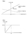
- Fig. 3 represents the relationship between the temperature and output of power storage device B.
- the solid line represents the output allowable power of power storage device B.
- the output allowable power of power storage device B is reduced as the temperature of power storage device B becomes lower.
- the state of charge (SOC) of power storage device B is reduced, the output of power storage device B will become lower than the rating, as shown in Fig. 4 . Therefore, the output allowable power of power storage device B will also be reduced if the SOC becomes lower.
- the output allowable power of power storage device B is estimated based on the temperature and SOC of power storage device B in the first embodiment when engine 4 is started.
- the estimated output allowable power is lower than a predetermined threshold power Pth represented by the dotted line, the boosting operation to be carried out by up-converter 10 is restricted.
- Threshold power Pth is determined in advance based on power Pg required for the startup of engine 4. Specifically, since power Pg required to start engine 4 can be estimated in advance depending upon the size of engine 4 and motor generator MG1, an appropriate value larger than power Pg can be set as threshold power Pth using equation (1) set forth above.
- threshold power Pth is increased as a function of reduction in the temperature in Fig. 3. Since the viscosity of the lubricating oil of engine 4 is increased as the temperature becomes lower, the cranking resistance is increased. This leads to increase of power Pg required to start engine 4.
- Fig. 5 is a flowchart to describe the control configuration of engine startup control unit 62 shown in Fig. 2 .
- the process in this flowchart is called from the main routine to be executed at a constant interval or every time a predetermined condition is established.
- engine startup control unit 62 determines whether a request to start engine 4 is made or not (step S10). This engine startup request is generated based on the running state of the vehicle or the SOC of power storage device B and the like at, for example, an external ECU not shown.
- step S10 determines whether a request to start engine 4 is made or not.
- This engine startup request is generated based on the running state of the vehicle or the SOC of power storage device B and the like at, for example, an external ECU not shown.
- control proceeds to step S80 without carrying out the series of steps set forth below.
- engine startup control unit 62 fetches temperature TB of power storage device B from temperature sensor 82 (step S20). Then, engine startup control unit 62 calculates the SOC of power storage device B (step S30).
- the SOC of power storage device B can be calculated by the well-known method using current IB, voltage VB, temperature TB, and the like of power storage device B.
- the SOC of power storage device B can be calculated at an external ECU to allow the SOC to be provided to engine startup control unit 62 from the external ECU.
- engine startup control unit 62 estimates an output allowable power Pmax of power storage device B based on temperature TB and the SOC of power storage device B (step S40).
- the relationship of the output allowable power of power storage device B with respect to the temperature and SOC thereof can be defined in a map in advance based on the relationship as shown in Figs. 3 and 4 , for example, to carry out estimation based on the prepared map.
- engine startup control unit 62 calculates threshold power Pth based on the power required to start engine 4 by the aforementioned method (step S50). Engine startup control unit 62 determines whether output allowable power Pmax of power storage device B is lower than threshold power Pth (step S60).
- step S60 When engine startup control unit 62 determines that output allowable power Pmax is lower than threshold power (YES at step S60), signal CTL to be output to converter control unit 64 is rendered active. In response, converter control unit 64 controls up-converter 10 such that the boosting rate of up-converter 10 is restricted to be below a prescribed value. Thus, the boosting rate of up-converter 10 is restricted to a level lower than the prescribed value (step S70).
- step S60 When determination is made that output allowable power Pmax is equal to or higher than threshold power Pth at step S60 (YES at step S60), engine startup control unit 62 proceeds to step S80. Control returns to the main routine.
- Fig. 6 is a detailed functional block diagram of converter control unit 64 shown in Fig. 2 .
- converter control unit 64 includes an inverter input voltage control calculation unit 102, a duty ratio calculation unit 104, and a PWM signal conversion unit 106.
- Inverter input voltage control calculation unit 102 calculates as optimum value (target value) of an inverter input voltage, i.e. a voltage control value Vcom, based on torque control values TR1 and TR2 and motor speed counts MRN1 and MRN2, when signal CTL from engine startup control unit 62 not shown is inactive.
- the calculated voltage control Vcom is output to duty ratio calculation unit 104.
- Inverter input voltage control calculation unit 102 calculates voltage control Vcom such that the boosting rate of up-converter 10 is restricted to be below a prescribed value when signal CTL is active.
- the calculated voltage control Vcom is output to duty ratio calculation unit 104.
- Duty ratio calculation unit 104 calculates the duty ratio to regulate voltage VH to voltage control Vcom based on voltages VL and VH from voltage sensors 72 and 74, respectively, and voltage control Vcom from inverter input voltage control calculation unit 102. The calculated duty ratio is provided to PWM signal conversion unit 106.
- PWM signal conversion unit 106 generates a PWM signal to turn on/off npn type transistors Q1 and Q2 of up-converter 10 based on the duty ratio received from duty ratio calculation unit 104.
- the generated PWM signal is provided to npn type transistors Q1 and Q2 of up-converter 10 as signal PWC.
- duty ratio calculation unit 104 may set a duty ratio determined in advance such that the boosting rate of up-converter 10 is restricted to be below a prescribed value, independent of voltage control Vcom from inverter input voltage control calculation unit 102 in the case where signal CTL received from engine startup control unit 62 is active.
- ECU 60 controls up-converter 10 such that the boosting rate of up-converter 10 is restricted to be below a prescribed value in a startup mode of engine 4 in the first embodiment. Therefore, the output voltage of up-converter 10 (input voltage of inverters 20 and 30) can be reduced. Thus, the loss at up-converter 10 and inverters 20 and 30 can be reduced, and the power charged to capacitor C2 can be also reduced. According to the first embodiment, sufficient power required to start engine 4 can be ensured. As a result, the power required to start engine 4 can be ensured even when in an extremely low temperature state where the output of power storage device B is significantly reduced and the cranking resistance of engine 4 is increased. Furthermore, power storage device B can be reduced in size.
- the first embodiment is directed to controlling up-converter 10 such that the boosting rate of up-converter 10 is restricted to be below a prescribed value when output allowable power Pmax is lower than threshold power Pth.
- the operation of up-converter 10 is stopped when output allowable power Pmax is lower than threshold power Pth.
- Fig. 7 is a flowchart to describe the control of up-converter 10 in an engine startup mode of the second embodiment. Referring to Fig. 7 , the process in this flowchart includes steps S72 and S74 instead of step S70 in the flowchart of Fig. 5 .
- step S60 when determination is made that output allowable power Pmax is lower than threshold power Pth at step S60 (YES at step S60), engine startup control unit 62 renders signal CTL that is to be output to converter control unit 64 active.
- converter control unit 64 stops up-converter 10 (step S72). Specifically, converter control unit 64 sets npn type transistor Q1 corresponding to the upper arm constantly ON, and sets npn type transistor Q2 corresponding to the lower arm constantly OFF. Accordingly, the boosting rate of up-converter 10 is set to the lowest value of 1. Voltage VH attains a level identical to that of voltage VB of power storage device B.
- engine startup control unit 62 renders signal CTL that is to be output to converter control unit 64 inactive.
- converter control unit 64 permits the operation of up-converter 10 (step S74). Specifically, converter control unit 64 controls up-converter 10 in a normal manner based on torque control values TR1 and TR2 and motor speed counts MRN1 and MRN2.
- the operation of up-converter 10 is ceased when engine 4 is started, as set forth above.
- an advantage similar to that of the first embodiment can be provided through simple control.
- Fig. 8 is a flowchart to describe the control of up-converter 10 at an engine startup mode of the third embodiment.
- the process in this flowchart includes step S 110 instead of steps S30-S60 in the flow chart of Fig. 5 .
- engine startup control unit 62 determines whether the fetched temperature TB is lower than a preset threshold value (step S110). This threshold value can be set to an appropriate temperature corresponding to a significant reduction in the output of power storage device B.
- step S110 When engine startup control unit 62 determines that temperature TB is lower than the threshold value (YES at step S110), control proceeds to step S70 where the boosting rate of up-converter 10 is restricted to be below a prescribed value. When determination is made that temperature TB is lower than the threshold value step S110 (NO at step S 110), engine startup control unit 62 proceeds to step S80.
- the boosting regulation of up-converter 10 can be restricted to a low temperature state where the output of power storage device B is degraded. Further, control at the startup of engine 4 can be rendered simple.
- Fig. 9 is a flowchart to describe control of up-converter 10 in an engine startup mode according to the fourth embodiment.
- the process shown in this flowchart includes steps S210 and S220 instead of steps S20-S60 in the flowchart of Fig. 5 .
- engine startup control unit 62 fetches temperature TE of engine 4 from temperature sensor 84 (step S210).
- engine startup control unit 62 determines whether the fetched temperature TE is lower than a preset threshold value (step S220).
- This threshold value can be set to an appropriate temperature corresponding to a significant increase in the cranking resistance of engine 4.
- step S220 When engine startup control unit 62 determines that temperature TE is lower than the threshold value (YES at step S220), control proceeds to step S70 where the boosting rate of up-converter 10 is restricted to be below a prescribed value. When determination is made that temperature TE is lower than the threshold value at step S220 (NO at step S220), engine startup control unit 62 proceeds to step S80.
- the boosting regulation of up-converter 10 can be restricted in a low temperature state where the cranking resistance of engine 4 increases. Furthermore, control at the time of starting engine 4 can be rendered simple.
- up-converter 10 can be stopped as in the second embodiment, instead of the control for restricting up-converter 10 such that the boosting rate of up-converter 10 is restricted to be below a prescribed value.
- the present invention is applicable to a general vehicle including an up-converter that can boost the voltage from a power storage device for supply to a starter motor.
- a general vehicle including an up-converter that can boost the voltage from a power storage device for supply to a starter motor.
- an idle-stop vehicle that automatically stops the engine temporarily when the vehicle is not running such as at stoplights, and then starts the engine by means of a starter motor when an engine startup condition is established, efficient usage of power is desired since engine startup is effected frequently.
- the present invention is suitable for such idle-stop vehicles.
- engine 4 and motor generator MG1 correspond to “internal combustion engine” and “rotating electric machine”, respectively, of the present invention.
- Up-converter 10 and inverter 20 correspond to “boosting device” and “driving device”, respectively, of the present invention.
- engine 60 corresponds to "control device” of the present invention.
Landscapes
- Engineering & Computer Science (AREA)
- Mechanical Engineering (AREA)
- Combustion & Propulsion (AREA)
- Chemical & Material Sciences (AREA)
- Transportation (AREA)
- Power Engineering (AREA)
- General Engineering & Computer Science (AREA)
- Automation & Control Theory (AREA)
- Life Sciences & Earth Sciences (AREA)
- Sustainable Development (AREA)
- Sustainable Energy (AREA)
- Electric Propulsion And Braking For Vehicles (AREA)
- Hybrid Electric Vehicles (AREA)
- Control Of Vehicle Engines Or Engines For Specific Uses (AREA)
Abstract
Description
- The present invention relates to a load driving apparatus, a vehicle incorporating the load driving apparatus, and a control method for the load driving apparatus. Particularly, the present invention relates to control for a load driving apparatus that drives a rotating electric machine that can start an internal combustion engine.
- Japanese Patent Laying-Open No.
2005-237149 - When the up-converter is inactive, the output voltage of the battery is supplied to the power supply line. When the up-converter is active, the voltage boosted by the up-converter is supplied to the power supply line. The up-converter operates intermittently in accordance with the operating period of the starter unit. Specifically, the voltage supplied to the starter unit is boosted by the up-converter in this power supply device for a vehicle when the engine is started by the starter unit.
- When the up-converter is operated, the loss at the up-converter as well as the loss at the inverter directed to driving the starter motor will be increased. Therefore, in the case where the temperature is extremely low such that the battery output is significantly reduced and the cranking resistance of the engine is increased, for example, the power to drive the starter motor at the time of engine startup may be so low that there is a possibility of not being able to start the engine.
- In view of the foregoing, an object of the present invention is to provide a load driving apparatus including a boosting device, capable of reducing power loss to ensure the engine startup power, and a vehicle incorporating the load driving apparatus.
- Another object of the present invention is to provide a control method for a load driving apparatus including a boosting device, capable of reducing power loss to ensure the engine startup power.
- According to the present invention, a load driving apparatus capable of driving a rotating electric machine having a rotational shaft coupled to an output shaft of an internal combustion engine includes a power storage device, a boosting device, a driving device, and a control device. The boosting device is configured to allow boosting of a voltage from the power storage device. The driving device receives an output voltage from the boosting device to drive the rotating electric machine. The control device controls the boosting device. The control device controls the boosting device such that a voltage boosting rate by the boosting device is restricted to be below a prescribed value when the rotating electric machine is driven to start the internal combustion engine.
- Preferably, the prescribed value is determined such that the output voltage from the boosting device is substantially equal to the voltage from the power storage device.
- In addition, the control device preferably stops the boosting device when the internal combustion engine is started.
- Preferably, the control device controls the boosting device such that the voltage boosting rate is restricted to be below a prescribed value when an output power from the power storage device is lower than a threshold value.
- Further preferably, the threshold value is determined based on the power required to start the internal combustion engine by the rotating electric machine.
- Preferably, the control device controls the boosting device such that the voltage boosting rate is restricted to be below a prescribed value when the temperature of the power storage device is lower than a prescribed temperature.
- In addition, the control device preferably controls the boosting device such that the voltage boosting rate is restricted to be below a prescribed value when the temperature of the internal combustion engine is lower than a prescribed temperature.
- Preferably, the power storage device is formed of a lithium-ion secondary battery.
- According to the present invention, a vehicle includes an internal combustion engine, a rotating electric machine having a rotational shaft connected to an output shaft of the internal combustion engine, and a load driving apparatus set forth above capable of driving the rotating electric machine.
- Further, according to the present invention, a control method for a load driving apparatus is directed to a control method for a load driving apparatus capable of driving a rotating electric machine having a rotational shaft coupled to an output shaft of an internal combustion engine. The load driving apparatus includes a power storage device, a boosting device, and a driving device. The boosting device is configured to allow boosting of a voltage from the power storage device. The driving device receives an output voltage from the boosting device to drive the rotating electric machine. The control method includes the steps of determining whether a request to drive the rotating electric machine to start the internal combustion engine is made or not, and restricting a voltage boosting rate by the boosting device to be below a prescribed value when determination is made that a request to start the internal combustion engine has been made.
- Preferably, the prescribed value is determined such that the output voltage is substantially equal to the voltage from the power storage device.
- Preferably, in the step of restricting the voltage boosting rate, the boosting device is stopped when determination is made that a request to start the internal combustion engine has been made.
- Preferably, the control method for a load driving apparatus further includes the step of determining whether an output power from the power storage device is lower than a threshold value. When determination is made that the output power is lower than the threshold value, the voltage boosting rate is restricted to be below the prescribed value in the step of restricting the voltage boosting rate.
- Further preferably, the threshold value is determined based on the power required to start the internal combustion engine by the rotating electric machine.
- Preferably, the method further includes the step of determining whether the temperature of the power storage device is lower than a prescribed temperature. When determination is made that the temperature of the power storage device is lower than the prescribed temperature, the voltage boosting rate is restricted to be below the prescribed value in the step of restricting the voltage boosting rate.
- Further preferably, the method further includes the step of determining whether the temperature of the internal combustion engine is lower than a prescribed temperature. When determination is made that the temperature of the internal combustion engine is lower than the prescribed temperature, the voltage boosting rate is restricted to be below the prescribed value in the step of restricting the voltage boosting rate.
- According to the present invention, the output voltage from the boosting device is reduced since the voltage boosting rate by the boosting device is restricted to be below a prescribed value when the rotating electric machine is driven to start the internal combustion engine. Accordingly, the loss at the boosting device is reduced. In addition, the loss at the driving device receiving the output voltage from the boosting device is also reduced.
- According to the present invention, sufficient power required to start the internal combustion engine can be ensured. As a result, even when in an extremely low temperature state where the output of the power storage device is significantly reduced and the cranking resistance of the internal combustion engine increases, the power required to start the internal combustion engine can be ensured. In addition, the power storage device can be reduced in size in accordance with the present invention.
-
-
Fig. 1 is an entire block diagram of a hybrid vehicle represented as an example of a vehicle in which a load driving apparatus according to a first embodiment of the present invention is incorporated. -
Fig. 2 is a functional block diagram of an ECU shown inFig. 1 . -
Fig. 3 is a diagram representing the relationship between the temperature and output of a power storage device. -
Fig. 4 is a diagram representing the relationship between the SOC and output of a power storage device. -
Fig. 5 is a flowchart to describe a control configuration of the engine startup control unit ofFig. 2 . -
Fig. 6 is a detailed functional block diagram of a converter control unit shown inFig. 2 . -
Fig. 7 is a flowchart to describe control of an up-converter in an engine startup mode according to a second embodiment. -
Fig. 8 is a flowchart to describe control of an up-converter in an engine startup mode according to a third embodiment. -
Fig. 9 is a flowchart to describe control of an up-converter in an engine startup mode according to a fourth embodiment. - Embodiments of the present invention will be described in detail hereinafter with reference to the drawings. In the drawings, the same or corresponding elements have the same reference characters allotted, and the description thereof will not be repeated.
-
Fig. 1 is an entire block diagram of a hybrid vehicle represented as an example of a vehicle in which a load driving apparatus according to the first embodiment of the present invention is incorporated. Referring toFig. 1 , thishybrid vehicle 100 includes awheel 2, apower split mechanism 3, anengine 4, and motor generators MG1 and MG2.Hybrid vehicle 100 further includes a power storage device B, an up-converter 10,inverters voltage sensors current sensors temperature sensors - Power split
mechanism 3 is coupled toengine 4 and motor generators MG1 and MG2 to split power therebetween. For example, a planetary gear mechanism including the three rotational shafts of a sun gear, a planetary carrier, and a ring gear can be employed aspower split mechanism 3. These three rotational shafts are connected to the rotational shaft of each ofengine 4 and motor generators MG1 and MG2, respectively. For example, by passing the crankshaft ofengine 4 through the center of a hollow rotor of motor generator MG1, mechanical connection ofpower split mechanism 3 withengine 4 and also motor generators MG1 and MG2 can be established. - The rotational shaft of motor generator MG2 is coupled to
wheel 2 by a reduction gear or differential gear not shown. In addition, a reduction gear for the rotational shaft of motor generator MG2 can be further incorporated inpower split mechanism 3. - Motor generator MG1 is incorporated into
hybrid vehicle 100 functioning as an electric motor that can startengine 4, and also as a power generator that can generate power using the motive force ofengine 4 afterengine 4 is started. Motor generator MG2 is incorporated intohybrid vehicle 100 functioning as an electric motor that can drivewheel 2. - Power storage device B is a direct current power supply that can be charged and discharged. For example, it is formed of a secondary battery of nickel hydrogen, lithium ions, and the like. Power storage device B supplies direct current power to power supply line PL1. Power storage device B receives the direct current power output from up-
converter 10 onto power supply line PL1 to be charged. -
Voltage sensor 70 detects a voltage VB of power storage device B to provide the detected voltage VB toECU 60.Current sensor 80 detects a current IB that is input to and output from power storage device B to provide the detected current IB toECU 60.Temperature sensor 82 detects a temperature TB of power storage device B to provide the detected temperature TB toECU 60.Current sensor 80 may be provided at power supply line PL1. - Capacitor C1 is connected between power supply line PL1 and ground line SL to smooth the voltage variation between power supply line PL1 and ground line SL.
Voltage sensor 72 detects a voltage VL across capacitor C1 to provide the detected voltage VL toECU 60. - Up-
converter 10 includes npn type transistors Q1 and Q2, diodes D1 and D2, and a reactor L. Npn type transistors Q1 and Q2 are connected in series between power supply line PL2 and ground line SL. Diodes D1 and D2 are connected antiparallel to npn type transistors Q1 and Q2, respectively. Reactor L is connected between power supply line PL1 and the connection node of npn type transistors Q1 and Q2. - Up-
converter 10 boosts the voltage of power supply line PL1 to provide the boosted voltage onto power supply line PL2 based on a signal PWC fromECU 60. Specifically, up-converter 10 stores the current flowing when npn type transistor Q2 is ON as the magnetic field energy at reactor L, and discharges the storage energy onto power supply line PL2 via diode D1 when npn type transistor Q2 is OFF to boost the voltage of power supply line PL1. - Since the power accumulated at reactor L becomes larger by increasing the ON duty of npn type transistor Q2, power of higher voltage can be obtained. By increasing the ON duty of npn type transistor Q1, the voltage of power supply line PL2 is reduced. By controlling the duty ratio of npn type transistors Q1 and Q2, the voltage of power supply line PL2 can be regulated to an arbitrary voltage level of at least the voltage on power supply line PL1.
- Capacitor C2 is connected between power supply line PL2 and ground line SL to smooth the voltage variation between power supply line PL2 and ground line SL.
Voltage sensor 74 detects a voltage VH across capacitor C2 to provide the detected voltage VH toECU 60. -
Inverters Inverter 20 drives motor generator MG1 in a power running mode or regenerative mode based on a signal PWI1 fromECU 60.Inverter 30 drives motor generator MG2 in a power running mode or regenerative mode based on a signal PWI2 fromECU 60. -
Current sensor 76 detects a motor current MCRT1 flowing to motor generator MG1 to provide the detected motor generator MCRT2 toECU 60.Current sensor 78 detects a motor current MCRT2 flowing to motor generator MG2 to provide the detected motor current MCRT2 toECU 60.Temperature sensor 84 detects a temperature TE ofengine 4 to provide the detected temperature TE toECU 60.Temperature sensor 84 may identify the temperature ofengine 4 by detecting the temperature of the coolant ofengine 4. -
ECU 60 receives voltages VL and VH fromvoltage sensors current sensors ECU 60 also receives torque control values TR1 and TR2 and motor speed counts MRN1 and MRN2 of motor generators MG1 and MG2 from an external ECU not shown.ECU 60 further receives voltage VB, current IB and temperature TB fromvoltage sensor 70,current sensor 80, andtemperature sensor 82, respectively, and temperature TE fromtemperature sensor 84. -
ECU 60 generates signals PWC, PWI1 and PWI2 to drive up-converter 10 and motor generators MG1 and MG2, respectively, based on the received signal, and provides the generated signals PWC, PWI1 and PWI2 to up-converter 10 andinverters -
Fig. 2 is a functional block diagram ofECU 60 ofFig. 1 . Referring toFig. 2 ,ECU 60 includes an enginestartup control unit 62, aconverter control unit 64, and first and secondinverter control units - When
engine 4 is started, enginestartup control unit 62 determines whether the output allowable power of power storage device B is below a predetermined threshold power by a method that will be described afterwards, based on temperature TB, voltage VB, and current IB of power storage device B, and temperature TE ofengine 4. When enginestartup control unit 62 determines that the output allowable power of power storage device B is below the threshold power, a signal CTL that will be provided toconverter control unit 64 is rendered active to instructconverter control unit 64 to restrict the boosting rate of up-converter 10 to be below a prescribed value. - When signal CTL from engine
startup control unit 62 is inactive,converter control unit 64 generates a signal PWC to turn on/off npn type transistors Q1 and Q2 of up-converter 10 by a method that will be described afterwards, based on torque control values TR1 and TR2, motor speed counts MRN1 and MRN2, and voltages VL and VH. The generated signal PWC is output to up-converter 10. - When signal CTL is active,
converter control unit 64 generates signal PWC to restrict the boosting rate of up-converter 10 to be below the prescribed value, and provides generated signal PWC to up-converter 10. This prescribed value is provided for the purpose of restricting the boosting by up-converter 10 whenengine 4 is started. The prescribed value is set to 1, or a value in the vicinity of 1. - First
inverter control unit 66 generates a PWM (Pulse Width Modulation) signal to driveinverter 20, based on torque control value TR1, motor current MCRT1 and voltage VH to provide the generated PWM signal toinverter 20 as signal PWI1. - Second
inverter control unit 68 generates a PWM signal to driveinverter 30 based on torque control value TR2, motor current MCRT2 and voltage VH to provide the generated PWM signal toinverter 30 as signal PWI2. - At
ECU 60, the boosting rate of up-converter 10 is restricted to be below the prescribed value for the purpose of restricting the boosting by up-converter 10 when the output allowable power of power storage device B is lower than a predetermined threshold power at the startup ofengine 4. The reason why the boosting by up-converter 10 is restricted is set forth below. - Power Pg required for the startup of
engine 4 can be represented by the following equation.
where Pb represents the power output from power storage device B, Pc represents the power charged to capacitors C1 and C2, Pg represents the effective power of motor generator MG1, Pm represents the effective power of motor generator MG2, Lc represents the loss at up-converter 10, Lg represents the loss atinverter 20, and Lm represents the loss atinverter 30. - By restricting the boosting effected by up-
converter 10, loss Lc at up-converter 10 can be reduced. Since the storage energy of a capacitor is proportional to the square of the voltage across the capacitor, reduction in voltage VH by restricting the boosting of up-converter 10 will cause reduction in the storage energy of capacitor C2. As a result, power Pc is reduced. In view of the loss at an inverter being proportional to the voltage, reduction in voltage VH leads to reduction in loss Lg and Lm atinverters - Thus, restricting the boosting by up-
converter 10 is extremely effective in ensuring power Pg required to startengine 4. The first embodiment is directed to restricting the boosting operation of up-converter 10 to ensure power Pg in an extremely low temperature state where the output allowable power of power storage device B is reduced. -
Fig. 3 represents the relationship between the temperature and output of power storage device B. Referring toFig. 3 , the solid line represents the output allowable power of power storage device B. As shown in the drawing, the output allowable power of power storage device B is reduced as the temperature of power storage device B becomes lower. In addition, when the state of charge (SOC) of power storage device B is reduced, the output of power storage device B will become lower than the rating, as shown inFig. 4 . Therefore, the output allowable power of power storage device B will also be reduced if the SOC becomes lower. - In view of the foregoing, the output allowable power of power storage device B is estimated based on the temperature and SOC of power storage device B in the first embodiment when
engine 4 is started. In the case where the estimated output allowable power is lower than a predetermined threshold power Pth represented by the dotted line, the boosting operation to be carried out by up-converter 10 is restricted. - Threshold power Pth is determined in advance based on power Pg required for the startup of
engine 4. Specifically, since power Pg required to startengine 4 can be estimated in advance depending upon the size ofengine 4 and motor generator MG1, an appropriate value larger than power Pg can be set as threshold power Pth using equation (1) set forth above. - The reason why threshold power Pth is increased as a function of reduction in the temperature in
Fig. 3 will be described here. Since the viscosity of the lubricating oil ofengine 4 is increased as the temperature becomes lower, the cranking resistance is increased. This leads to increase of power Pg required to startengine 4. -
Fig. 5 is a flowchart to describe the control configuration of enginestartup control unit 62 shown inFig. 2 . The process in this flowchart is called from the main routine to be executed at a constant interval or every time a predetermined condition is established. - Referring to
Fig. 5 , enginestartup control unit 62 determines whether a request to startengine 4 is made or not (step S10). This engine startup request is generated based on the running state of the vehicle or the SOC of power storage device B and the like at, for example, an external ECU not shown. When enginestartup control unit 62 determines that a startup request ofengine 4 is not made (NO at step S10), control proceeds to step S80 without carrying out the series of steps set forth below. - When determination is made that a startup request of
engine 4 is made at step S10 (YES at step S10), enginestartup control unit 62 fetches temperature TB of power storage device B from temperature sensor 82 (step S20). Then, enginestartup control unit 62 calculates the SOC of power storage device B (step S30). The SOC of power storage device B can be calculated by the well-known method using current IB, voltage VB, temperature TB, and the like of power storage device B. The SOC of power storage device B can be calculated at an external ECU to allow the SOC to be provided to enginestartup control unit 62 from the external ECU. - Next, engine
startup control unit 62 estimates an output allowable power Pmax of power storage device B based on temperature TB and the SOC of power storage device B (step S40). As one method of estimating output allowable power Pmax, the relationship of the output allowable power of power storage device B with respect to the temperature and SOC thereof can be defined in a map in advance based on the relationship as shown inFigs. 3 and 4 , for example, to carry out estimation based on the prepared map. - Then, engine
startup control unit 62 calculates threshold power Pth based on the power required to startengine 4 by the aforementioned method (step S50). Enginestartup control unit 62 determines whether output allowable power Pmax of power storage device B is lower than threshold power Pth (step S60). - When engine
startup control unit 62 determines that output allowable power Pmax is lower than threshold power (YES at step S60), signal CTL to be output toconverter control unit 64 is rendered active. In response,converter control unit 64 controls up-converter 10 such that the boosting rate of up-converter 10 is restricted to be below a prescribed value. Thus, the boosting rate of up-converter 10 is restricted to a level lower than the prescribed value (step S70). - When determination is made that output allowable power Pmax is equal to or higher than threshold power Pth at step S60 (YES at step S60), engine
startup control unit 62 proceeds to step S80. Control returns to the main routine. -
Fig. 6 is a detailed functional block diagram ofconverter control unit 64 shown inFig. 2 . Referring toFig. 6 ,converter control unit 64 includes an inverter input voltagecontrol calculation unit 102, a dutyratio calculation unit 104, and a PWMsignal conversion unit 106. - Inverter input voltage
control calculation unit 102 calculates as optimum value (target value) of an inverter input voltage, i.e. a voltage control value Vcom, based on torque control values TR1 and TR2 and motor speed counts MRN1 and MRN2, when signal CTL from enginestartup control unit 62 not shown is inactive. The calculated voltage control Vcom is output to dutyratio calculation unit 104. - Inverter input voltage
control calculation unit 102 calculates voltage control Vcom such that the boosting rate of up-converter 10 is restricted to be below a prescribed value when signal CTL is active. The calculated voltage control Vcom is output to dutyratio calculation unit 104. - Duty
ratio calculation unit 104 calculates the duty ratio to regulate voltage VH to voltage control Vcom based on voltages VL and VH fromvoltage sensors control calculation unit 102. The calculated duty ratio is provided to PWMsignal conversion unit 106. - PWM
signal conversion unit 106 generates a PWM signal to turn on/off npn type transistors Q1 and Q2 of up-converter 10 based on the duty ratio received from dutyratio calculation unit 104. The generated PWM signal is provided to npn type transistors Q1 and Q2 of up-converter 10 as signal PWC. - It is to be noted that duty
ratio calculation unit 104 may set a duty ratio determined in advance such that the boosting rate of up-converter 10 is restricted to be below a prescribed value, independent of voltage control Vcom from inverter input voltagecontrol calculation unit 102 in the case where signal CTL received from enginestartup control unit 62 is active. - Thus,
ECU 60 controls up-converter 10 such that the boosting rate of up-converter 10 is restricted to be below a prescribed value in a startup mode ofengine 4 in the first embodiment. Therefore, the output voltage of up-converter 10 (input voltage ofinverters 20 and 30) can be reduced. Thus, the loss at up-converter 10 andinverters engine 4 can be ensured. As a result, the power required to startengine 4 can be ensured even when in an extremely low temperature state where the output of power storage device B is significantly reduced and the cranking resistance ofengine 4 is increased. Furthermore, power storage device B can be reduced in size. - The first embodiment is directed to controlling up-
converter 10 such that the boosting rate of up-converter 10 is restricted to be below a prescribed value when output allowable power Pmax is lower than threshold power Pth. In the second embodiment, the operation of up-converter 10 is stopped when output allowable power Pmax is lower than threshold power Pth. -
Fig. 7 is a flowchart to describe the control of up-converter 10 in an engine startup mode of the second embodiment. Referring toFig. 7 , the process in this flowchart includes steps S72 and S74 instead of step S70 in the flowchart ofFig. 5 . - Specifically, when determination is made that output allowable power Pmax is lower than threshold power Pth at step S60 (YES at step S60), engine
startup control unit 62 renders signal CTL that is to be output toconverter control unit 64 active. In response,converter control unit 64 stops up-converter 10 (step S72). Specifically,converter control unit 64 sets npn type transistor Q1 corresponding to the upper arm constantly ON, and sets npn type transistor Q2 corresponding to the lower arm constantly OFF. Accordingly, the boosting rate of up-converter 10 is set to the lowest value of 1. Voltage VH attains a level identical to that of voltage VB of power storage device B. - When determination is made that output allowable power Pmax is equal to or higher than threshold power Pth at step S60 (NO at step S60), engine
startup control unit 62 renders signal CTL that is to be output toconverter control unit 64 inactive. In response,converter control unit 64 permits the operation of up-converter 10 (step S74). Specifically,converter control unit 64 controls up-converter 10 in a normal manner based on torque control values TR1 and TR2 and motor speed counts MRN1 and MRN2. - According to the second embodiment, the operation of up-
converter 10 is ceased whenengine 4 is started, as set forth above. Thus, an advantage similar to that of the first embodiment can be provided through simple control. -
Fig. 8 is a flowchart to describe the control of up-converter 10 at an engine startup mode of the third embodiment. Referring toFig. 8 , the process in this flowchart includesstep S 110 instead of steps S30-S60 in the flow chart ofFig. 5 . Specifically, upon fetching temperature TB of power storage device B at step S20, enginestartup control unit 62 determines whether the fetched temperature TB is lower than a preset threshold value (step S110). This threshold value can be set to an appropriate temperature corresponding to a significant reduction in the output of power storage device B. - When engine
startup control unit 62 determines that temperature TB is lower than the threshold value (YES at step S110), control proceeds to step S70 where the boosting rate of up-converter 10 is restricted to be below a prescribed value. When determination is made that temperature TB is lower than the threshold value step S110 (NO at step S 110), enginestartup control unit 62 proceeds to step S80. - Thus, the boosting regulation of up-
converter 10 can be restricted to a low temperature state where the output of power storage device B is degraded. Further, control at the startup ofengine 4 can be rendered simple. -
Fig. 9 is a flowchart to describe control of up-converter 10 in an engine startup mode according to the fourth embodiment. Referring toFig. 9 , the process shown in this flowchart includes steps S210 and S220 instead of steps S20-S60 in the flowchart ofFig. 5 . Specifically, when determination is made that a request to startengine 4 is made at step S10, enginestartup control unit 62 fetches temperature TE ofengine 4 from temperature sensor 84 (step S210). - Then, engine
startup control unit 62 determines whether the fetched temperature TE is lower than a preset threshold value (step S220). This threshold value can be set to an appropriate temperature corresponding to a significant increase in the cranking resistance ofengine 4. - When engine
startup control unit 62 determines that temperature TE is lower than the threshold value (YES at step S220), control proceeds to step S70 where the boosting rate of up-converter 10 is restricted to be below a prescribed value. When determination is made that temperature TE is lower than the threshold value at step S220 (NO at step S220), enginestartup control unit 62 proceeds to step S80. - According to the fourth embodiment, the boosting regulation of up-
converter 10 can be restricted in a low temperature state where the cranking resistance ofengine 4 increases. Furthermore, control at the time of startingengine 4 can be rendered simple. - In the third and fourth embodiments set forth above, up-
converter 10 can be stopped as in the second embodiment, instead of the control for restricting up-converter 10 such that the boosting rate of up-converter 10 is restricted to be below a prescribed value. - Although each of the embodiments set forth above is based on the case where the load driving apparatus is incorporated in a hybrid vehicle, the present invention is applicable to a general vehicle including an up-converter that can boost the voltage from a power storage device for supply to a starter motor. Particularly in the case of an idle-stop vehicle that automatically stops the engine temporarily when the vehicle is not running such as at stoplights, and then starts the engine by means of a starter motor when an engine startup condition is established, efficient usage of power is desired since engine startup is effected frequently. The present invention is suitable for such idle-stop vehicles.
- In the above description,
engine 4 and motor generator MG1 correspond to "internal combustion engine" and "rotating electric machine", respectively, of the present invention. Up-converter 10 andinverter 20 correspond to "boosting device" and "driving device", respectively, of the present invention. Further,engine 60 corresponds to "control device" of the present invention. - It should be understood that the embodiments disclosed herein are illustrative and non-restrictive in every respect. The scope of the present invention is defined by the terms of the claims, rather than the description of the embodiments above, and is intended to include any modification within the scope and meaning equivalent to the terms of the claims.
Claims (16)
- A load driving apparatus capable of driving a rotating electric machine having a rotational shaft coupled to an output shaft of an internal combustion engine, comprising:a power storage device,a boosting device configured to allow boosting of a voltage from said power storage device,a driving device receiving an output voltage from said boosting device to drive said rotating electric machine, anda control device controlling said boosting device such that a voltage boosting rate by said boosting device is restricted to be below a prescribed value when said rotating electric machine is driven to start said internal combustion engine.
- The load driving apparatus according to claim 1, wherein said prescribed value is determined such that said output voltage is substantially equal to the voltage from said power storage device.
- The load driving apparatus according to claim 1, wherein said control device stops said boosting device when said internal combustion engine is started.
- The load driving apparatus according to any one of claims 1-3, wherein said control device controls said boosting device such that said voltage boosting rate is restricted to be below said prescribed value when an output power from said power storage device is lower than a threshold value.
- The load driving apparatus according to claim 4, wherein said threshold value is determined based on power required to drive said internal combustion engine by said rotating electric machine.
- The load driving apparatus according to any one of claims 1-3, wherein said control device controls said boosting device such that said voltage boosting rate is restricted to be below said prescribed value when a temperature of said power storage device is lower than a prescribed temperature.
- The load driving apparatus according to any one of claims 1-3, wherein said control device controls said boosting device such that said voltage boosting rate is restricted to be below said prescribed value when a temperature of said internal combustion engine is lower than a prescribed temperature.
- The load driving apparatus according to claim 1, wherein said power storage device is formed of a lithium-ion secondary battery.
- A vehicle comprising:an internal combustion engine,a rotating electric machine having a rotational shaft connected to an output shaft of said internal combustion engine, anda load driving apparatus capable of driving said rotating electric machine,said load driving apparatus includinga power storage device,a boosting device configured to allow boosting of a voltage from said power storage device,a driving device receiving an output voltage from said boosting device to drive said rotating electric machine, anda control device controlling said boosting device such that a voltage boosting rate by said boosting device is restricted to be below a prescribed value when said rotating electric machine is driven to start said internal combustion engine.
- A control method for a load driving apparatus capable of driving a rotating electric machine having a rotational shaft coupled to an output shaft of an internal combustion engine, said load driving apparatus including
a power storage device,
a boosting device configured to allow boosting of a voltage from said power storage device, and
a driving device receiving an output voltage from said boosting device to drive said rotating electric machine,
said control method comprising the steps of:determining whether a request to drive said rotating electric machine to start said internal combustion engine is made or not, andrestricting a voltage boosting rate by said boosting device to be below a prescribed value when determination is made that a request to start said internal combustion engine has been made. - The control method for a load driving apparatus according to claim 10, wherein said prescribed value is determined such that said output voltage is substantially equal to the voltage from said power storage device.
- The control method for a load driving apparatus according to claim 10, wherein said boosting device is stopped when determination is made that a request to start said internal combustion engine has been made in said step of restricting the voltage boosting rate.
- The control method for a load driving apparatus according to any one of claims 10-12, further comprising the step of determining whether an output power of said power storage device is lower than a threshold value,
wherein said voltage boosting rate is restricted to be below the prescribed value in said step of restricting said voltage boosting rate when determination is made that said output power is lower than said threshold value. - The control method for a load driving apparatus according to claim 13, wherein said threshold value is determined based on power required to start said internal combustion engine by said rotating electric machine.
- The control method for a load driving apparatus according to any one of claims 10-12, further comprising the step of determining whether a temperature of said power storage device is lower than a prescribed temperature,
wherein said voltage boosting rate is restricted to be below the prescribed value in said step of restricting the voltage boosting rate when determination is made that the temperature of said power storage device is lower than said prescribed temperature. - The control method for a load driving apparatus according to any one of claims 10-12, further comprising the step of determining whether a temperature of said internal combustion engine is lower than a prescribed temperature,
wherein said voltage boosting rate is restricted to be below the prescribed value in said step of restricting said voltage boosting rate when determination is made that the temperature of said internal combustion engine is lower than said prescribed temperature.
Applications Claiming Priority (2)
| Application Number | Priority Date | Filing Date | Title |
|---|---|---|---|
| JP2006119289A JP4325637B2 (en) | 2006-04-24 | 2006-04-24 | Load driving device and vehicle equipped with the same |
| PCT/JP2007/059143 WO2007126038A1 (en) | 2006-04-24 | 2007-04-20 | Load drive device, vehicle using the same, and load drive device control method |
Publications (3)
| Publication Number | Publication Date |
|---|---|
| EP2011710A1 true EP2011710A1 (en) | 2009-01-07 |
| EP2011710A4 EP2011710A4 (en) | 2011-05-18 |
| EP2011710B1 EP2011710B1 (en) | 2012-05-16 |
Family
ID=38655559
Family Applications (1)
| Application Number | Title | Priority Date | Filing Date |
|---|---|---|---|
| EP07742578A Active EP2011710B1 (en) | 2006-04-24 | 2007-04-20 | Load driving apparatus, vehicle incorporating the same, and control method for load driving apparatus |
Country Status (8)
| Country | Link |
|---|---|
| US (1) | US7821214B2 (en) |
| EP (1) | EP2011710B1 (en) |
| JP (1) | JP4325637B2 (en) |
| KR (1) | KR101010293B1 (en) |
| CN (1) | CN101421141B (en) |
| CA (1) | CA2642549C (en) |
| RU (1) | RU2402444C2 (en) |
| WO (1) | WO2007126038A1 (en) |
Cited By (1)
| Publication number | Priority date | Publication date | Assignee | Title |
|---|---|---|---|---|
| EP2538068A1 (en) * | 2011-06-22 | 2012-12-26 | Volvo Car Corporation | Method and arrangement for improving the performance of an electrical system of a vehicle |
Families Citing this family (30)
| Publication number | Priority date | Publication date | Assignee | Title |
|---|---|---|---|---|
| JP4297951B2 (en) * | 2007-05-25 | 2009-07-15 | トヨタ自動車株式会社 | Vehicle drive system |
| GB2452246B (en) * | 2007-07-19 | 2012-01-11 | Ford Global Tech Llc | A micro-hybrid motor vehicle |
| JP2009227080A (en) * | 2008-03-21 | 2009-10-08 | Toyota Motor Corp | Power output device and vehicle equipped with the same, and driving device and control method for them |
| JP5029915B2 (en) * | 2008-07-31 | 2012-09-19 | アイシン・エィ・ダブリュ株式会社 | Rotating electrical machine control system and vehicle drive system |
| JP5029914B2 (en) | 2008-07-31 | 2012-09-19 | アイシン・エィ・ダブリュ株式会社 | Rotating electrical machine control system and vehicle drive system |
| JP5428353B2 (en) * | 2009-01-23 | 2014-02-26 | 日産自動車株式会社 | Vehicle drive control device and vehicle drive control method |
| US8170737B2 (en) * | 2009-04-30 | 2012-05-01 | GM Global Technology Operations LLC | Method of controlling vehicle powertrain and vehicle control system |
| JP5289209B2 (en) * | 2009-06-26 | 2013-09-11 | ダイハツ工業株式会社 | Idle stop control device |
| JP5335594B2 (en) * | 2009-07-23 | 2013-11-06 | 株式会社日本自動車部品総合研究所 | Automatic stop and start device for internal combustion engine |
| TWI463402B (en) * | 2009-09-04 | 2014-12-01 | Chi Mei Comm Systems Inc | Scheduled tasks management system and method |
| JP5182434B2 (en) * | 2009-11-26 | 2013-04-17 | トヨタ自動車株式会社 | Charger |
| JP2011190734A (en) * | 2010-03-15 | 2011-09-29 | Fujitsu Ten Ltd | Idling stop device and method for starting engine |
| JP5358622B2 (en) * | 2011-06-24 | 2013-12-04 | 本田技研工業株式会社 | Rotating electrical machine control device |
| KR20130011293A (en) | 2011-07-21 | 2013-01-30 | 현대자동차주식회사 | Battery charging system for vehicle, and control method of the same |
| JP5923906B2 (en) * | 2011-09-21 | 2016-05-25 | トヨタ自動車株式会社 | Vehicle and vehicle control method |
| KR101284331B1 (en) * | 2011-12-09 | 2013-07-08 | 성균관대학교산학협력단 | Recharge systen for green car and method thereof |
| JP2013219982A (en) * | 2012-04-11 | 2013-10-24 | Toyota Industries Corp | Dc-ac inverter |
| US8766567B2 (en) | 2012-08-02 | 2014-07-01 | Snap-On Incorporated | Battery control and protective element validation method |
| FR2995466B1 (en) * | 2012-09-13 | 2014-08-29 | Renault Sa | SYSTEM AND METHOD FOR MANAGING THE POWER SUPPLY OF AT LEAST ONE AUTOMATIC RESTART EQUIPMENT OF A VEHICLE HEAT ENGINE |
| JP6065530B2 (en) | 2012-11-09 | 2017-01-25 | トヨタ自動車株式会社 | Vehicle control apparatus and vehicle |
| EP2844865B1 (en) * | 2013-06-20 | 2016-04-27 | Briggs & Stratton Corporation | Internal combustion engine including electric starting system powered by lithium-ion battery |
| JP5928442B2 (en) | 2013-12-24 | 2016-06-01 | トヨタ自動車株式会社 | Vehicle power supply |
| JP5987846B2 (en) * | 2014-01-27 | 2016-09-07 | トヨタ自動車株式会社 | Hybrid vehicle |
| DE102015102163B4 (en) * | 2014-02-18 | 2021-01-28 | Subaru Corporation | Battery voltage control and method for controlling a battery voltage |
| JP5915675B2 (en) * | 2014-02-21 | 2016-05-11 | トヨタ自動車株式会社 | Electric vehicle |
| JP6216671B2 (en) * | 2014-03-27 | 2017-10-18 | 本田技研工業株式会社 | Three-phase AC power generation starter device |
| JP6172114B2 (en) * | 2014-10-28 | 2017-08-02 | トヨタ自動車株式会社 | Hybrid car |
| CN104290612B (en) * | 2014-11-03 | 2016-05-18 | 清华大学 | Active voltage control method and control system for a motor system |
| CN105197009B (en) * | 2015-10-16 | 2017-10-24 | 北京汽车股份有限公司 | BSG motors method of supplying power to, system, control unit for vehicle and automobile |
| JP6195651B1 (en) * | 2016-07-19 | 2017-09-13 | 三菱電機株式会社 | Power converter and voltage sensor characteristic abnormality diagnosis method |
Family Cites Families (24)
| Publication number | Priority date | Publication date | Assignee | Title |
|---|---|---|---|---|
| JPH05328530A (en) | 1992-03-16 | 1993-12-10 | Toyota Motor Corp | Power source for hybrid vehicle |
| JPH07115704A (en) * | 1993-10-14 | 1995-05-02 | Toyota Motor Corp | Retarder device |
| RU2200871C2 (en) | 2000-11-13 | 2003-03-20 | Открытое акционерное общество "АВТОВАЗ" | Starter-generator control device with unit forming pressure values of field current and stator current vector component in longitudinal and cross axes |
| JP4411811B2 (en) | 2001-08-24 | 2010-02-10 | トヨタ自動車株式会社 | Control device for hybrid vehicle |
| JP3566252B2 (en) * | 2001-12-12 | 2004-09-15 | 本田技研工業株式会社 | Hybrid vehicle and control method thereof |
| JP4013739B2 (en) | 2002-11-11 | 2007-11-28 | トヨタ自動車株式会社 | Voltage conversion apparatus, voltage conversion method, and computer-readable recording medium recording a program for causing a computer to execute voltage conversion |
| JP2004183570A (en) * | 2002-12-04 | 2004-07-02 | Nissan Motor Co Ltd | Engine starter |
| JP2004208409A (en) | 2002-12-25 | 2004-07-22 | Denso Corp | Power control device for vehicle |
| JP3661689B2 (en) * | 2003-03-11 | 2005-06-15 | トヨタ自動車株式会社 | Motor drive device, hybrid vehicle drive device including the same, and computer-readable recording medium storing a program for causing a computer to control the motor drive device |
| JP2005160284A (en) | 2003-05-13 | 2005-06-16 | Sumitomo Electric Ind Ltd | Power converter and electric vehicle drive system |
| JP3783710B2 (en) | 2003-11-04 | 2006-06-07 | 日産自動車株式会社 | Vehicle motor control apparatus and vehicle motor control method |
| JP4474939B2 (en) | 2004-02-20 | 2010-06-09 | トヨタ自動車株式会社 | Vehicle power supply |
| JP4367391B2 (en) * | 2005-09-01 | 2009-11-18 | トヨタ自動車株式会社 | Charge control device and electric vehicle |
| JP4799133B2 (en) * | 2005-11-08 | 2011-10-26 | オムロンオートモーティブエレクトロニクス株式会社 | Motor control device |
| JP4710588B2 (en) * | 2005-12-16 | 2011-06-29 | トヨタ自動車株式会社 | Boost converter controller |
| JP4305462B2 (en) * | 2006-03-09 | 2009-07-29 | トヨタ自動車株式会社 | Vehicle drive power supply system |
| JP4802849B2 (en) * | 2006-05-09 | 2011-10-26 | トヨタ自動車株式会社 | Motor drive device |
| JP4462243B2 (en) * | 2006-07-10 | 2010-05-12 | トヨタ自動車株式会社 | Load driving device and vehicle equipped with the same |
| JP2008061487A (en) * | 2006-07-31 | 2008-03-13 | Toyota Motor Corp | Power supply system, vehicle equipped with the same, power storage device temperature rise control method, and computer-readable recording medium storing a program for causing a computer to execute power storage device temperature rise control |
| JP4356715B2 (en) * | 2006-08-02 | 2009-11-04 | トヨタ自動車株式会社 | Power supply device and vehicle equipped with power supply device |
| JP4211831B2 (en) * | 2006-09-14 | 2009-01-21 | トヨタ自動車株式会社 | HYBRID VEHICLE, HYBRID VEHICLE CONTROL METHOD, AND COMPUTER-READABLE RECORDING MEDIUM CONTAINING PROGRAM FOR CAUSING COMPUTER TO EXECUTE THE CONTROL METHOD |
| JP4155321B2 (en) * | 2006-09-25 | 2008-09-24 | トヨタ自動車株式会社 | Hybrid vehicle display device, hybrid vehicle, and hybrid vehicle display method |
| JP5011940B2 (en) * | 2006-10-16 | 2012-08-29 | トヨタ自動車株式会社 | Power supply device and vehicle |
| JP4715766B2 (en) * | 2007-02-13 | 2011-07-06 | トヨタ自動車株式会社 | Boosting system failure diagnosis device, boosting circuit control device, and vehicle |
-
2006
- 2006-04-24 JP JP2006119289A patent/JP4325637B2/en not_active Expired - Lifetime
-
2007
- 2007-04-20 WO PCT/JP2007/059143 patent/WO2007126038A1/en not_active Ceased
- 2007-04-20 RU RU2008146058/11A patent/RU2402444C2/en active
- 2007-04-20 KR KR1020087028137A patent/KR101010293B1/en active Active
- 2007-04-20 CA CA2642549A patent/CA2642549C/en active Active
- 2007-04-20 EP EP07742578A patent/EP2011710B1/en active Active
- 2007-04-20 US US12/223,645 patent/US7821214B2/en active Active
- 2007-04-20 CN CN200780013551XA patent/CN101421141B/en active Active
Cited By (3)
| Publication number | Priority date | Publication date | Assignee | Title |
|---|---|---|---|---|
| EP2538068A1 (en) * | 2011-06-22 | 2012-12-26 | Volvo Car Corporation | Method and arrangement for improving the performance of an electrical system of a vehicle |
| US9752547B2 (en) | 2011-06-22 | 2017-09-05 | Volvo Car Corporation | Electrical system for a vehicle with start/stop |
| US10036360B2 (en) | 2011-06-22 | 2018-07-31 | Volvo Car Corporation | Electrical system for a vehicle with start/stop |
Also Published As
| Publication number | Publication date |
|---|---|
| US20090021200A1 (en) | 2009-01-22 |
| CN101421141B (en) | 2012-06-06 |
| RU2008146058A (en) | 2010-05-27 |
| EP2011710A4 (en) | 2011-05-18 |
| CA2642549C (en) | 2010-10-05 |
| WO2007126038A1 (en) | 2007-11-08 |
| EP2011710B1 (en) | 2012-05-16 |
| KR101010293B1 (en) | 2011-01-25 |
| RU2402444C2 (en) | 2010-10-27 |
| CA2642549A1 (en) | 2007-11-08 |
| JP2007290478A (en) | 2007-11-08 |
| US7821214B2 (en) | 2010-10-26 |
| CN101421141A (en) | 2009-04-29 |
| KR20090009875A (en) | 2009-01-23 |
| JP4325637B2 (en) | 2009-09-02 |
Similar Documents
| Publication | Publication Date | Title |
|---|---|---|
| EP2011710B1 (en) | Load driving apparatus, vehicle incorporating the same, and control method for load driving apparatus | |
| CN101020424B (en) | Control device and control method for electric vehicle | |
| EP1319548B1 (en) | Hybrid vehicle and control method therefor | |
| KR100708923B1 (en) | Motor Drive Device, Hybrid Automobile Drive Device Using The Same, and Computer Readable Recording Medium Containing Program For Causing Computer To Execute Control of Motor Drive Device | |
| EP1858152B1 (en) | Load drive device, vehicle, and abnormality processing method in load drive device | |
| EP1717945B1 (en) | Motor driving apparatus | |
| EP2743150B1 (en) | Vehicle, vehicle control method and vehicle control device | |
| KR20090122244A (en) | Hybrid vehicle | |
| US20140076104A1 (en) | Engine starting system and engine starting method | |
| KR100958710B1 (en) | Load drive apparatus and motored vehicle having the same mounted thereon | |
| US10259342B2 (en) | Vehicle | |
| JP3912337B2 (en) | COMPUTER-READABLE RECORDING MEDIUM RECORDING HYBRID VEHICLE AND PROGRAM FOR CAUSING COMPUTER TO CONTROL IN HYBRID | |
| JP6530443B2 (en) | Low voltage battery deterioration detection system and vehicle equipped with the system | |
| JP2020048266A (en) | Power supply | |
| JP2005204363A (en) | Vehicle power supply | |
| JP2016130106A (en) | Drive device | |
| JP2016129460A (en) | Power supply | |
| JP7115366B2 (en) | power system | |
| JP2013013201A (en) | Electric vehicle |
Legal Events
| Date | Code | Title | Description |
|---|---|---|---|
| PUAI | Public reference made under article 153(3) epc to a published international application that has entered the european phase |
Free format text: ORIGINAL CODE: 0009012 |
|
| 17P | Request for examination filed |
Effective date: 20080819 |
|
| AK | Designated contracting states |
Kind code of ref document: A1 Designated state(s): AT BE BG CH CY CZ DE DK EE ES FI FR GB GR HU IE IS IT LI LT LU LV MC MT NL PL PT RO SE SI SK TR |
|
| AX | Request for extension of the european patent |
Extension state: AL BA HR MK RS |
|
| DAX | Request for extension of the european patent (deleted) | ||
| RBV | Designated contracting states (corrected) |
Designated state(s): DE FR GB |
|
| A4 | Supplementary search report drawn up and despatched |
Effective date: 20110419 |
|
| GRAP | Despatch of communication of intention to grant a patent |
Free format text: ORIGINAL CODE: EPIDOSNIGR1 |
|
| GRAS | Grant fee paid |
Free format text: ORIGINAL CODE: EPIDOSNIGR3 |
|
| GRAA | (expected) grant |
Free format text: ORIGINAL CODE: 0009210 |
|
| RTI1 | Title (correction) |
Free format text: LOAD DRIVING APPARATUS, VEHICLE INCORPORATING THE SAME, AND CONTROL METHOD FOR LOAD DRIVING APPARATUS |
|
| AK | Designated contracting states |
Kind code of ref document: B1 Designated state(s): DE FR GB |
|
| REG | Reference to a national code |
Ref country code: GB Ref legal event code: FG4D |
|
| REG | Reference to a national code |
Ref country code: DE Ref legal event code: R096 Ref document number: 602007022682 Country of ref document: DE Effective date: 20120719 |
|
| REG | Reference to a national code |
Ref country code: GB Ref legal event code: 746 Effective date: 20130128 |
|
| RAP2 | Party data changed (patent owner data changed or rights of a patent transferred) |
Owner name: TOYOTA JIDOSHA KABUSHIKI KAISHA |
|
| PLBE | No opposition filed within time limit |
Free format text: ORIGINAL CODE: 0009261 |
|
| STAA | Information on the status of an ep patent application or granted ep patent |
Free format text: STATUS: NO OPPOSITION FILED WITHIN TIME LIMIT |
|
| REG | Reference to a national code |
Ref country code: DE Ref legal event code: R084 Ref document number: 602007022682 Country of ref document: DE Effective date: 20130125 |
|
| 26N | No opposition filed |
Effective date: 20130219 |
|
| REG | Reference to a national code |
Ref country code: DE Ref legal event code: R097 Ref document number: 602007022682 Country of ref document: DE Effective date: 20130219 |
|
| REG | Reference to a national code |
Ref country code: FR Ref legal event code: PLFP Year of fee payment: 10 |
|
| REG | Reference to a national code |
Ref country code: FR Ref legal event code: PLFP Year of fee payment: 11 |
|
| REG | Reference to a national code |
Ref country code: FR Ref legal event code: PLFP Year of fee payment: 12 |
|
| REG | Reference to a national code |
Ref country code: DE Ref legal event code: R082 Ref document number: 602007022682 Country of ref document: DE Representative=s name: TBK, DE Ref country code: DE Ref legal event code: R081 Ref document number: 602007022682 Country of ref document: DE Owner name: DENSO CORPORATION, KARIYA-CITY, JP Free format text: FORMER OWNER: TOYOTA JIDOSHA KABUSHIKI KAISHA, TOYOTA-SHI, AICHI-KEN, JP |
|
| PGFP | Annual fee paid to national office [announced via postgrant information from national office to epo] |
Ref country code: FR Payment date: 20230309 Year of fee payment: 17 |
|
| PGFP | Annual fee paid to national office [announced via postgrant information from national office to epo] |
Ref country code: GB Payment date: 20230302 Year of fee payment: 17 |
|
| P01 | Opt-out of the competence of the unified patent court (upc) registered |
Effective date: 20230517 |
|
| GBPC | Gb: european patent ceased through non-payment of renewal fee |
Effective date: 20240420 |
|
| PG25 | Lapsed in a contracting state [announced via postgrant information from national office to epo] |
Ref country code: GB Free format text: LAPSE BECAUSE OF NON-PAYMENT OF DUE FEES Effective date: 20240420 |
|
| PG25 | Lapsed in a contracting state [announced via postgrant information from national office to epo] |
Ref country code: FR Free format text: LAPSE BECAUSE OF NON-PAYMENT OF DUE FEES Effective date: 20240430 |
|
| PG25 | Lapsed in a contracting state [announced via postgrant information from national office to epo] |
Ref country code: GB Free format text: LAPSE BECAUSE OF NON-PAYMENT OF DUE FEES Effective date: 20240420 Ref country code: FR Free format text: LAPSE BECAUSE OF NON-PAYMENT OF DUE FEES Effective date: 20240430 |
|
| PGFP | Annual fee paid to national office [announced via postgrant information from national office to epo] |
Ref country code: DE Payment date: 20250422 Year of fee payment: 19 |