EP2010988B1 - System and method for manage and control near field communication for a mobile multifunctional device when the device is uncharged or only partially charged - Google Patents
System and method for manage and control near field communication for a mobile multifunctional device when the device is uncharged or only partially charged Download PDFInfo
- Publication number
- EP2010988B1 EP2010988B1 EP06727528.9A EP06727528A EP2010988B1 EP 2010988 B1 EP2010988 B1 EP 2010988B1 EP 06727528 A EP06727528 A EP 06727528A EP 2010988 B1 EP2010988 B1 EP 2010988B1
- Authority
- EP
- European Patent Office
- Prior art keywords
- battery
- mobile electronic
- nfc
- near field
- multifunctional device
- Prior art date
- Legal status (The legal status is an assumption and is not a legal conclusion. Google has not performed a legal analysis and makes no representation as to the accuracy of the status listed.)
- Active
Links
- 238000004891 communication Methods 0.000 title claims description 97
- 238000000034 method Methods 0.000 title claims description 23
- 230000015654 memory Effects 0.000 claims description 23
- 230000001413 cellular effect Effects 0.000 claims description 16
- 238000004590 computer program Methods 0.000 claims description 4
- 238000007726 management method Methods 0.000 description 11
- 238000004146 energy storage Methods 0.000 description 5
- 230000006870 function Effects 0.000 description 5
- 229920001690 polydopamine Polymers 0.000 description 4
- 241001025261 Neoraja caerulea Species 0.000 description 3
- 238000013459 approach Methods 0.000 description 3
- 230000006399 behavior Effects 0.000 description 3
- 238000013461 design Methods 0.000 description 2
- 238000001514 detection method Methods 0.000 description 2
- 238000007599 discharging Methods 0.000 description 2
- 230000006855 networking Effects 0.000 description 2
- 230000008569 process Effects 0.000 description 2
- 238000012545 processing Methods 0.000 description 2
- 230000002035 prolonged effect Effects 0.000 description 2
- 239000002699 waste material Substances 0.000 description 2
- 102100024210 CD166 antigen Human genes 0.000 description 1
- 101000980840 Homo sapiens CD166 antigen Proteins 0.000 description 1
- XUIMIQQOPSSXEZ-UHFFFAOYSA-N Silicon Chemical compound [Si] XUIMIQQOPSSXEZ-UHFFFAOYSA-N 0.000 description 1
- 238000013475 authorization Methods 0.000 description 1
- 230000008901 benefit Effects 0.000 description 1
- 230000005540 biological transmission Effects 0.000 description 1
- 238000013500 data storage Methods 0.000 description 1
- 230000007123 defense Effects 0.000 description 1
- 238000010586 diagram Methods 0.000 description 1
- 238000005516 engineering process Methods 0.000 description 1
- 230000005284 excitation Effects 0.000 description 1
- 239000000284 extract Substances 0.000 description 1
- 230000000977 initiatory effect Effects 0.000 description 1
- 238000007689 inspection Methods 0.000 description 1
- 230000008447 perception Effects 0.000 description 1
- 230000002085 persistent effect Effects 0.000 description 1
- 230000008054 signal transmission Effects 0.000 description 1
- 229910052710 silicon Inorganic materials 0.000 description 1
- 239000010703 silicon Substances 0.000 description 1
- 230000001360 synchronised effect Effects 0.000 description 1
- 230000007704 transition Effects 0.000 description 1
- 230000002618 waking effect Effects 0.000 description 1
Images


Classifications
-
- H—ELECTRICITY
- H04—ELECTRIC COMMUNICATION TECHNIQUE
- H04B—TRANSMISSION
- H04B5/00—Near-field transmission systems, e.g. inductive or capacitive transmission systems
- H04B5/40—Near-field transmission systems, e.g. inductive or capacitive transmission systems characterised by components specially adapted for near-field transmission
- H04B5/48—Transceivers
-
- G—PHYSICS
- G06—COMPUTING; CALCULATING OR COUNTING
- G06F—ELECTRIC DIGITAL DATA PROCESSING
- G06F1/00—Details not covered by groups G06F3/00 - G06F13/00 and G06F21/00
- G06F1/26—Power supply means, e.g. regulation thereof
- G06F1/32—Means for saving power
- G06F1/3203—Power management, i.e. event-based initiation of a power-saving mode
- G06F1/3206—Monitoring of events, devices or parameters that trigger a change in power modality
- G06F1/3212—Monitoring battery levels, e.g. power saving mode being initiated when battery voltage goes below a certain level
-
- G—PHYSICS
- G06—COMPUTING; CALCULATING OR COUNTING
- G06F—ELECTRIC DIGITAL DATA PROCESSING
- G06F1/00—Details not covered by groups G06F3/00 - G06F13/00 and G06F21/00
- G06F1/26—Power supply means, e.g. regulation thereof
- G06F1/32—Means for saving power
- G06F1/3203—Power management, i.e. event-based initiation of a power-saving mode
- G06F1/3234—Power saving characterised by the action undertaken
- G06F1/3287—Power saving characterised by the action undertaken by switching off individual functional units in the computer system
-
- H—ELECTRICITY
- H04—ELECTRIC COMMUNICATION TECHNIQUE
- H04B—TRANSMISSION
- H04B1/00—Details of transmission systems, not covered by a single one of groups H04B3/00 - H04B13/00; Details of transmission systems not characterised by the medium used for transmission
- H04B1/38—Transceivers, i.e. devices in which transmitter and receiver form a structural unit and in which at least one part is used for functions of transmitting and receiving
- H04B1/40—Circuits
-
- H—ELECTRICITY
- H04—ELECTRIC COMMUNICATION TECHNIQUE
- H04M—TELEPHONIC COMMUNICATION
- H04M1/00—Substation equipment, e.g. for use by subscribers
- H04M1/72—Mobile telephones; Cordless telephones, i.e. devices for establishing wireless links to base stations without route selection
- H04M1/724—User interfaces specially adapted for cordless or mobile telephones
- H04M1/72403—User interfaces specially adapted for cordless or mobile telephones with means for local support of applications that increase the functionality
- H04M1/72409—User interfaces specially adapted for cordless or mobile telephones with means for local support of applications that increase the functionality by interfacing with external accessories
- H04M1/72412—User interfaces specially adapted for cordless or mobile telephones with means for local support of applications that increase the functionality by interfacing with external accessories using two-way short-range wireless interfaces
-
- H—ELECTRICITY
- H04—ELECTRIC COMMUNICATION TECHNIQUE
- H04W—WIRELESS COMMUNICATION NETWORKS
- H04W52/00—Power management, e.g. TPC [Transmission Power Control], power saving or power classes
- H04W52/02—Power saving arrangements
- H04W52/0209—Power saving arrangements in terminal devices
- H04W52/0261—Power saving arrangements in terminal devices managing power supply demand, e.g. depending on battery level
- H04W52/0274—Power saving arrangements in terminal devices managing power supply demand, e.g. depending on battery level by switching on or off the equipment or parts thereof
- H04W52/0277—Power saving arrangements in terminal devices managing power supply demand, e.g. depending on battery level by switching on or off the equipment or parts thereof according to available power supply, e.g. switching off when a low battery condition is detected
-
- Y—GENERAL TAGGING OF NEW TECHNOLOGICAL DEVELOPMENTS; GENERAL TAGGING OF CROSS-SECTIONAL TECHNOLOGIES SPANNING OVER SEVERAL SECTIONS OF THE IPC; TECHNICAL SUBJECTS COVERED BY FORMER USPC CROSS-REFERENCE ART COLLECTIONS [XRACs] AND DIGESTS
- Y02—TECHNOLOGIES OR APPLICATIONS FOR MITIGATION OR ADAPTATION AGAINST CLIMATE CHANGE
- Y02D—CLIMATE CHANGE MITIGATION TECHNOLOGIES IN INFORMATION AND COMMUNICATION TECHNOLOGIES [ICT], I.E. INFORMATION AND COMMUNICATION TECHNOLOGIES AIMING AT THE REDUCTION OF THEIR OWN ENERGY USE
- Y02D10/00—Energy efficient computing, e.g. low power processors, power management or thermal management
-
- Y—GENERAL TAGGING OF NEW TECHNOLOGICAL DEVELOPMENTS; GENERAL TAGGING OF CROSS-SECTIONAL TECHNOLOGIES SPANNING OVER SEVERAL SECTIONS OF THE IPC; TECHNICAL SUBJECTS COVERED BY FORMER USPC CROSS-REFERENCE ART COLLECTIONS [XRACs] AND DIGESTS
- Y02—TECHNOLOGIES OR APPLICATIONS FOR MITIGATION OR ADAPTATION AGAINST CLIMATE CHANGE
- Y02D—CLIMATE CHANGE MITIGATION TECHNOLOGIES IN INFORMATION AND COMMUNICATION TECHNOLOGIES [ICT], I.E. INFORMATION AND COMMUNICATION TECHNOLOGIES AIMING AT THE REDUCTION OF THEIR OWN ENERGY USE
- Y02D30/00—Reducing energy consumption in communication networks
- Y02D30/70—Reducing energy consumption in communication networks in wireless communication networks
Definitions
- the present invention relates to the field of mobile electronic multifunctional devices and methods for its operation. Especially the present invention pertains to mobile electronic multifunctional devices capable of performing wireless data communication.
- the present invention relates in particular to the field of near field communication enabled mobile electronic devices and methods for their operation. More particularly the present invention pertains to methods to manage and control near field communication in situations where the terminal is not or only partially powered.
- Plastic contact-less cards RFID cards
- Terminals or mobile battery powered devices having e.g. terminal-integrated RFID communication logics with RFID tag emulation functionality are already known.
- document WO 2005045744 discloses an RFID APPARATUS comprising transmission means for receiving demodulating and transmitting an RF signals.
- the RFID apparatus disclosed in that document has means to respond to an RF reader device, in tag emulation mode, and means to function as an RF reader device, in reader mode.
- WO 2006010943 disclosed a MULTI-TAG EMULATOR.
- a device capable of emulating a plurality of RF data storage devices in a single device is disclosed.
- Another document US 6776339 pertains to a wireless communication device having a contactless interface for a smart card reader.
- US2004/176032A1 and WO2005/093644A1 disclose wireless terminals which include a reader device.
- the reader device is operable in an active communication (reader) mode or a passive communication (tag) mode depending on the power supply state of the terminal.
- Another document referring to the technical field of the present invention is the international patent application with the number WO 2005008575 .
- an apparatus capable of operating in transponder mode is disclosed, wherein the transponder mode does not require power.
- an active electrostatic transceiver (104) is provided that has electrostatic electrodes, an energy storage means (360) such as a battery and a transceiver circuit for communication within an electrostatic RFID communication system.
- the transceiver circuit (300) includes power management features so that the energy storage means is not quickly depleted. Additionally, the transceiver circuit includes amplifiers and filters so that the read range is further increased and noise sources are better filtered out.
- the transceiver circuit has a clock extractor that extracts a clock from the incoming data signal such that the clock and the data signal are synchronized so that demodulating the data from the data signal is simplified.
- the transceiver circuit (300) has its own clock generator for initiating transmission of signals so that a reader need not have an exciter to generate an excitation signal.
- Each embodiment of the transceiver circuit has power management features so that power is conserved. Additionally, each transceiver circuit (300) has the ability to operate in a passive mode, when there is insufficient charge in the energy storage means (360) or a lower power mode is desirable.
- US2006079296 (A1 ) discloses a voltage supply device for use in portable devices that comprises a connection which is designed to connect an energy storage device, and a first means which is designed to provide a first supply voltage when the energy stored in the energy storage device is above a threshold value and not to provide a supply voltage when the stored energy is below the threshold value.
- the voltage supply device has a second means which is designed to provide a second supply voltage for operating a contactless interface irrespective of the threshold value.
- NFC/RFID emulation
- multifunctional devices such as NFC/RFID (emulation) enabled music players, mobile telephones, PDAs, palmtops, communicators, TV-devices and the like portable battery operated devices
- NFC/RFID emulation
- the battery of the device may be discharged so that a operation of the device and consequently of the NFC/RFID (emulation) functionality is no longer provided, or at least the control of the NFC/RFID (emulation) functionality is lost.
- a user of NFC/RFID (emulation) functionality for providing e.g. a subway ticket may lose the capability for providing his ticket to an inspection machine or person with the loss of the battery and consequently the loss of NFC/RFID (emulation) functionality.
- a user of a weak/empty battery device may lose his authorization to e.g. enter or use a public transport device when the battery of the device used to emulate the NFC/RFID (emulation) functionality gets weak or discharged. That is, a user may not only be able to enjoy the primary function of the device but also no longer able to enjoy/use the functionality provided by the NFC/RFID (emulation) functionality of the device. This is an important problem that needs to be solved in order to get user acceptance in integrating contact-less payment and/or travel cards into mobile battery powered devices.
- the device may be capable of operating in card emulation/transponder mode without requiring power (such as e.g. by an RFID tag stuck onto the device).
- the above mentioned problem can occur also when e.g. the battery has been removed from the multifunctional device while a user accesses the NFC/RFID functionality of e.g. a mobile telephone. It is desirable to have a multifunctional device that enable a user to use NFC/RFID functionality even in case of low/empty charging condition of said battery. (The conventional approach of providing a dedicated battery or a dedicated charge source for the components in question or the combination of NFC/RFID functionality based on completely passive RFID technology is however considered to be not providing satisfying results.)
- NFC/RFID functionality of a mobile electronic multifunctional device even in situations where no battery is connected to the device.
- the mobile electronic multifunctional device is mobile and intended to be battery powered, and is therefore provided with an interface to connect a battery to said mobile electronic multifunctional device.
- the mobile electronic multifunctional device is provided with a battery control circuit connected to said battery interface (and maybe to the rest of said device).
- the battery control circuit is provided to control the operation of said mobile electronic multifunctional device in accordance with a battery charging condition of a battery connected to said mobile electronic multifunctional device and to control also the utilization of the residual energy available on a battery connected to said battery interface.
- the component to provide said interface to said (a component providing said at least one) first functionality is provided to enable the device to implement the device with a first operability, for example a portable TV-set, a DVD, HD-DVD, Blue-Ray, MPX- player, a radio, a music (e.g. MP3) player, portable gaming console, a versatile device functionality such as e.g. PDA, a palm-top, a communicator, a (GPS- or Galileo-) navigator, a surveillance device or e.g. a mobile or cellular telephone functionality.
- the component providing said first functionality may comprise a user interface, to enable the user to actively interact with the mobile electronic multifunctional device to use said first functionality.
- the interface to the NFC-communication component may be used to provide an NFC-communication functionality to the multifunctional device. With the interface to a device providing an NFC-communication functionality and the interface to (a component providing) said at least one first functionality the electronic device becomes a (potentially) multifunctional device.
- the NFC-communication component may also be connected to the battery interface of the mobile electronic multifunctional device. It may be intended to connect an NFC-communication component with a user interface component to take provisions to use said (at least one) first functionality to grant e.g. access via said interface to a NFC-communication component to said NFC-communication component via said user interface of said component to provide said (at least one) first functionality.
- Said software cut-off condition, said hardware cut-off condition, and said battery cut-off condition may be summarized under the main category battery empty condition (of a connected battery), while the normal operation condition may be denoted as battery full condition.
- the software cut-off condition and the hardware cut-off condition may be implemented as the same operation condition. In the battery cut-off condition even the battery control circuit may be disconnected from the battery (or the battery is removed).
- the hardware cut-off condition may also include the software cut-off condition, and that the battery cut-off may include both hardware and software cut-off conditions.
- the mobile multifunctional device may be configured to allow (possibly) different configurations of said NFC-communication component for "normal operation” and one of said "battery empty conditions” (of a battery connected or disconnected to said battery interface).
- the mobile electronic multifunctional device may allow an (expectedly restricted) "emergency" use of an NFC-communication component (connected via said interface to said NFC-component) in at least one of said battery empty conditions (including the battery disconnected condition).
- Said storage may be pre-programmed to allow e.g. one or two selected NFC-communication functionalities to be performed in one of said battery empty conditions (of a connected battery) when e.g. an NFC-communication event is detected by the NFC-communication component (connected via said interface to said NFC-component) in one of said battery empty conditions (of a connected battery), and may allow all NFC functionalities in the normal operation condition.
- the storage may be programmed to use different battery voltage thresholds for software/hardware cut-off for cutting off the first functionality at higher battery voltages (of a connected battery) on one hand and cutting off said NFC-communication functionality (of an NFC component connected via said interface to said NFC-component) at lower battery voltages (of a connected battery) on the other hand. It is to be noted that in this context the operation conditions are differentiated.
- the present invention may also be embodied as a chipset for a mobile multifunctional device.
- said mobile electronic multifunctional device further comprises a component providing said at least one functionality, connected to said interface to said at least one functionality.
- said mobile electronic multifunctional device further comprises a battery, connected to said battery interface.
- said mobile electronic multifunctional device further comprises an NFC-communication component, connected to said interface to a NFC-communication component.
- the device is already provided with the battery powered (at least one) first functionality.
- the interface may be embodied as a connection of e.g. as an application protocol interface for said first functionality. It may be noted that the interface is not necessarily disconnectable. That is the interface may be embodied as a hard wired connection, logical links (in a software implementation) or even as printed circuits on a printed circuit board (or the respective implementation in an integrated circuit chip).
- the component said (at least one) first functionality (via said interface to said first functionality), is provided to enable the device to implement the device with a first operability, for example a portable TV-set, a DVD, HD-DVD, Blue-Ray, MPX- player, a radio, a music (e.g. MP3) player, portable gaming console, a versatile device functionality such as e.g. PDA, a palm-top, a communicator, a (GPS- or Galileo-) navigator, a surveillance device or e.g. a mobile or cellular telephone functionality.
- the component providing said first functionality may comprise a user interface, to enable the user to actively interact with the mobile electronic multifunctional device to use said first functionality.
- the mobile electronic multifunctional device may comprise also a battery connected to said battery interface.
- the battery may be embodied as an interchangeable battery (module) like it is known from conventional cellular telephones.
- The, battery may be embodied as an interchangeable primer batteries like it is known from conventional small electronic devices.
- the battery may be embodied as a built in battery like it is known from some portable MP3 player devices.
- the interface to the first functionality the battery is not necessarily disconnectable. That is, the interface may be embodied as a hard wired connection or as printed circuits on a printed circuit board.
- the battery control circuit may control also the utilization of the residual energy available on a battery connected to said battery interface.
- Said mobile electronic multifunctional device may further comprise an NFC-communication component, connected to said interface to a NFC-communication component.
- the interface is not necessarily disconnectable. That is, the interface may be embodied as a hard wired connection, logical links (in a software implementation) or even as printed circuits on a printed circuit board (or the respective implementation in an integrated circuit chip).
- Said NFC-communication component may be provided with a dedicated memory, that stores information on how operate said NFC-component or said mobile electronic multifunctional device under at least two of said normal operation, software cut-off, hardware cut-off and/or said battery cut-off conditions upon detecting a NFC-wakeup event.
- This embodiment pertains to a device in which said storage is used as a dedicated component to be able to ensure that the NFC-communication component can access this dedicated storage event under software/hardware cut-off conditions of the said first functionality.
- the dedicated memory may have the additional advantage that it may be tailored to be low voltage operable, so that the power consumption of the NFC-communication component can be prolonged with respect to the operation of e.g. a single memory device used by the NFC-communication component and the component providing said at least one first functionality.
- This implementation may suggest the use of low voltage operable components (memories) in at least the NFC-communication component.
- the use of low voltage operable components is already known in the field especially of battery-less RF-powered NFC-transponders.
- Said dedicated memory may be operable in a partially powered state. This embodiment may enable especially a low power operation of said NFC-communication component, as not the whole memory has to be powered e.g. just by a received radio frequency field (e.g. from a NFC-reader device nearby).
- a received radio frequency field e.g. from a NFC-reader device nearby.
- Said mobile electronic multifunctional device may be provided with a user interface, wherein said memory is configurable by a user input via said interface.
- the user interface may be primarily provided for the first functionality of said mobile multifunctional device. Different user interface elements may be implemented for the first functionality and said NFC-communication component or functionality.
- Said mobile electronic multifunctional device is may be provided with a storage to store configurations of said battery control circuit for at least two of said operation conditions.
- operation of the battery control circuit may rely on a storage so that the battery control circuit utilizes/controls/directs the energy of the battery to the NFC-components or modules based on the current operation condition. Due to the fact that the battery control relies in an storage and not on a hard wired control logic the device may be provided with different powered state to not powered state transition paths.
- Said mobile electronic multifunctional device may be provided with a user interface, and said battery control circuit may be configurable by a user input via said interface. That is, in this embodiment the user is capable of defining also the actual operation of the device/ battery control circuit (NFC front-end visible/not visible) in addition to the selection what will be visible. In this embodiment of the present invention the user may also select the different software and (partial) hardware cut-off procedures and states. With this embodiment the user may select how the device may behave if and when the battery power fades. With this embodiment the user may also select under which conditions the battery control circuit may power the NFC-components, or e.g. only said memory so support a NFC transponder functionality of the NFC-components of said device.
- the user interface may provide means for the user to select the terminal behavior in power off-mode when the terminal is still powered, i.e. beforehand.
- Said first functionality may further comprise cellular telephone functionality.
- the mobile multifunctional device may be implemented as an NFC-enabled mobile telephone.
- the NFC component of the NFC-communication enabled mobile telephone even if the battery power of the battery is not sufficient to operate e.g. the GSM radio stage of the mobile telephone.
- the mobile (or cellular) telephone is used as a access ticket for e.g. underground transportation facilities it becomes necessary to be able to access the transportation facility even if the battery of the mobile telephone gets discharged by trying to connect to a (not present) base station in the underground.
- Said first functionality may comprise data reproduction functionality such as an MP2 and MP3 decoder/player, a portable TV and the like. It is also envisaged to combine e.g. an MP3 player with a communication device such as mobile telephone and a device with an NFC-capability to a multifunctional device.
- data reproduction functionality such as an MP2 and MP3 decoder/player, a portable TV and the like. It is also envisaged to combine e.g. an MP3 player with a communication device such as mobile telephone and a device with an NFC-capability to a multifunctional device.
- Said battery may be detachable from said apparatus.
- the different configurations of said mobile electronic device for at least two of said operation conditions may for example comprise the restriction of the execution of certain programs or the provision of power to different components of the mobile electronic device.
- this embodiment may be construed as a device with the capability of defining additional operation conditions such as "play audio but video cutoff condition", “operate electronic paper display bur disable touch screen”.... without limitation. It may also be envisaged to define the different voltages (or charging conditions) for each of said present or newly definable operation conditions.
- a mobile multifunctional device receives/detects an NFC-communication event and reacts/answers this detected communication event in accordance with (data related to) the current operation condition of said device.
- Operating a NFC-component of said mobile electronic multifunctional device in accordance with said determined configuration of said NFC-communication component may further comprise powering said NFC-component by the battery control circuit even under said hardware cut-off condition. If the device is under battery cut-off, the only energy that is available to operate the NFC- components will be coming from external (RF-) sources.
- RF- external
- Said determination of said current operation state may be performed before the detection of Said determination of said current operation state may be performed before the detection of said NFC-communication event. That is, the NFC-component may be aware that it is in a powered down state, and therefore know that it/the mobile electronic multifunctional device is currently in a software cut-off or hardware cut-off state when detecting the NFC-communication event, and therefore may also determine in advance how to answer a receive or how to configure the NFC-communication component of a multifunctional device.
- the battery cut-off condition may be considered as an operation condition even if severe restriction in operation have to be expected.
- the device may only have two different operation conditions for which configurations for the NFC-communication component are defined, e.g. the normal operation condition and the software cut-off condition.
- a user may have the options to select different NFC-communication configuration for each of the cited operation conditions (even if this implementation has the drawback that a user may not intuitively determine in which of the different battery low conditions the device currently is).
- the method may further comprise using the received RF energy from said NFC-communication event to power said NFC-communication component of a mobile electronic multifunctional device.
- This implementation is may be especially useful for NFC components capable of acting as an NFC-transponder in case of hardware- and battery cut-off conditions.
- the RF powered NFC-communication component may send a signal to the battery control circuit to request e.g. short period power supply by from the battery. With the power from the residual battery the NFC-component may handle/answer the NFC-communication request.
- the method may further comprise using a part of said received RF energy of said NFC-communication event, to (at least partially) read out (or power) a memory device, in which information is stored related to the configuration of said NFC-communication component related to said detected operation condition of the device is stored, i.e. for at least two of said normal operation conditions, software cut-off condition, hardware cut-off condition, or battery cut-off condition.
- the determination of said current operation condition may determine that the operation condition of the mobile electronic multifunctional device is software cut-off or hardware cut-off condition.
- said method may further comprise powering said NFC-component of said mobile electronic multifunctional device, after detecting said NFC communication event.
- This may be implemented e.g. by notifying a battery management circuit/power management circuit of said mobile electronic multifunctional device to power said NFC-component for e.g. a predetermined period of time.
- the method may further comprise receiving a user input defining the configurations of said NFC-communication component for said normal operation condition, software cut-off condition, hardware cut-off condition and battery cut-off, and storing said configurations of said NFC-communication component in a storage of said mobile electronic multifunctional device.
- the method may further comprise detecting a voltage of the battery of said mobile electronic multifunctional device by said battery control circuit, determining the current operation condition of said mobile electronic multifunctional device, determining a configuration of said mobile electronic multifunctional device related to said detected operation condition, and operating said mobile electronic multifunctional device in accordance with said determined configuration of said mobile electronic multifunctional device.
- This embodiment enables a user or a manufacturer of the mobile multifunctional device to define the actual operation of the device/ battery control circuit (in addition to the configuration of the NFC front-end as visible or not visible) in addition to the selection what will be visible. Due to the storage/memory the battery control circuit can access, the manufacturer has the possibility to select different configurations of the mobile multifunctional device for each of the operation conditions. That is, in this embodiment of the present invention a manufacturer/user may select and/or define the operation conditions e.g. by defining additional operation sates such as a "software cut-off condition one" wherein e.g. a mobile telephone enters an "offline mode" or only sporadically connects to a base station to request for short messages pending or the like. It is also envisaged to implement new (partial) hardware cutoff conditions, wherein e.g. only the backlight of a display is hardware cut-off to saver battery power to prolong the operation time of the mobile multifunctional device.
- additional operation sates such as a "software
- At least a manufacturer may have the freedom to select and/define the operation of the battery control circuit so that the battery control circuit utilizes/controls/directs the energy of the battery to the (software/hardware) components (e.g. to the NFC modules) based on the current operation condition.
- the battery control circuit utilizes/controls/directs the energy of the battery to the (software/hardware) components (e.g. to the NFC modules) based on the current operation condition.
- the method may further comprise receiving a user input defining the configurations of said mobile electronic multifunctional device for at least one of said normal operation, software cut-off, hardware cut-off and/or battery cut-off conditions, and storing said configurations of said NFC-communication component in a storage of said mobile electronic multifunctional device.
- the user may be able to define also the actual operation of the device/ battery control circuit (e.g. of the NFC front-end visible/not visible) in addition to the selection what will be visible. That is the user may have the possibility to configure the battery control circuit so that the battery control circuit utilizes/controls/directs the energy of the battery to the components of the mobile multifunctional device according to the current battery voltage/charging condition.
- the user may have the freedom to select a "hard cut-off" to enable full functionality of the mobile electronic multifunctional device or may have the freedom to select one (or a number) of applications that should be kept functional for a maximum time.
- the user may select if the device should be able to operate the NFC-component for a prolonged period of time, or if he wants to enable e.g. TV-operation only for at least more than 50% charged battery.
- This aspect is applicable to nearly any application or operational parameter of a mobile electronic multifunctional device.
- the user may select all applications and components that may be cut-off for each charging condition of the battery and/or each operation condition. It may also possible to define different paths through said defined operation conditions for each one of successive power cut-offs. It may be possible to define e.g. in a mobile cellular telephone a battery cutoff for a the counter may be reset e.g. by a charging process.
- a computer program product comprising computer program code sections for carrying out the steps of the method of the first aspect when said program is run on a mobile electronic multifunctional device.
- FIG. 1 is an example illustration of a mobile electronic multifunctional device according to the state of the art.
- the depicted embodiment is implemented as a near field communication enabled cellular telephone as a first functionality and a NFC communication component as a second functionality.
- the device is provided with a base-band processor and a firmware as running on a central processing unit.
- the central processing unit is connected at one side with a network interface for providing the radio network access for the mobile or cellular network part of the mobile electronic multifunctional device (MEMD).
- MEMD mobile electronic multifunctional device
- On the left side of the MEMD the NFC-communication functionality is implemented by the NFC-chip and the secure chip for NFC-communication.
- the MEMD is additionally provided with a user interface for providing user with means to control and use the MEMD.
- the interface may comprise displays, keys, keypads or keyboards, loudspeakers, vibration actuators/sensors, lights, infrared/electric/radio connectors and the like.
- the MEMD may be controlled under normal operation conditions (i.e. the device is switched on) as a mobile telephone and a NFC-communication device capable of emulating different NFC devices such as NC reader or NFC (e.g. an RFID) transponder. That is, such a device is capable of serving as NFC communication device and as a mobile telephone.
- both functionalities are no longer available. That is in case the user has made a long phone call (e.g. in a train) until the battery of the device is empty, and the phone call has been interrupted, the user can also no longer use the NFC-communication component of the device. If the user has a NFC based access system and uses a NFC based public transport payment system, the user is not only able to use the phone, the user is no longer able to use e.g. the public transport or enter the house in case the battery of the NFC-enabled device is empty.
- FIG 2 is an example illustration of a mobile electronic multifunctional device according to one embodiment of the present invention in a normal operation condition in an NFC-Reader/Writer mode.
- the device is depicted in a normal operation condition.
- the device of the present invention is provided with a power management stage or battery control circuit.
- the battery control circuit or power management stage is connected to a battery (not depicted) and to the base-band/firmware processor. It is also envisaged to provide dedicated connections to the NFC components such as e.g. NFC chip itself and the secure chip. These additional connections may be provided to enable the battery control circuit (or power supply circuit) to selectively power each component (and especially the components necessary to perform NFC communication and/or NFC-tag emulation).
- the single components of the MEMD may be provided with power in normal operation condition (switched-on device).
- switched-on device In the MEMD only the secure NFC-chip is not powered.
- the user interfaces of the MEMD may be powered as known from screensaver conditions or key-lock conditions known from modern cellular telephones.
- the present invention relates to the operation of mobile terminals equipped with NFC/RFID and more particularly how to manage and control card emulation in situations where the terminal is not powered, there is not a lot of different features to be recognized in a powered condition of the device.
- the present invention provides a memory connected to the NFC-communication component that in this embodiment is integrated in the base-band/firmware processor.
- the MEMD is further provided with secure smart card module.
- Figure 3 depicts the mobile electronic multifunctional device of figure 2 in a normal operation condition in an NFC-Card Emulation Mode according to one embodiment of the present invention.
- the NFC components are only operated by the battery if and when an external radio frequency field is detected by the NFC component.
- the operation mode of the NFC component is NFC/RFID-tag emulation. To prevent unnecessary waste of power the NFC components are only powered when needed, that is when e.g. a radio frequency (RF-) signal is detected.
- RF- radio frequency
- Figure 4 depicts an illustration of the mobile electronic multifunctional device of figures 2 and 3 in a battery low or device off condition in an NFC-Card emulation mode according to one embodiment of the present invention.
- the primary functionality i.e. the component providing said first functionality
- the power management and the base-band and firmware processor are powered for providing means to control the operation of the NFC-components.
- the power management and the base-band and firmware processor are also normally in a not powered state and may be powered by the battery if a signal from the NFC component is received indicating that the NFC component detected an RF signal.
- This external RF field detected means that the RF front-end detects an RF field and that it is capable of "tuning to", i.e. an RF field with matching frequency and other characteristics.
- the present invention may be used in a switched-off state of the MEMD, in a software cut-off state or in a hardware cut-off state entered because the battery voltage or charging condition has fallen below a predetermined threshold.
- Figure 4 clearly indicates an implementation that may be used to utilize the (residual) power left in the battery in power off-situations when the NFC/RFID front-end detects an external field.
- the depicted device selectively powers parts of a system in order to provide "power off", software cut-off ore hardware cut-off functionality for end user of the MEMD.
- this invention may provide a user with an NFC-functionality in both cases under phone-on and battery discharged/phone off conditions. Anyhow the implementation is not capable of providing NFC-operability under battery cut-off (or battery completely discharged) conditions, as there is not enough energy left in the battery to power the NFC component (the battery control circuit or the base-band and firmware processor).
- the depicted implementation may provide under some of the cut-off conditions an NFC-functionality and in some of the battery cutoff conditions no NFC-functionality, which may lead to confused and frustrated users, as the device sometimes when it seems to be "switched off” may be able to operate the NFC-component, and sometimes not. Additionally a user may no longer be sure that all functions (especially the NFC-functions) are switched off when the user turns off the device.
- the invention can enable a user to control the card emulation visibility in all operational states.
- the device may even have means to perform certain predefined operations upon receiving battery cut-off or hardware cut-off situations so that the user preferred/previously selected information is provided in the tag logic memory so that the device is capable of providing the preferred output to a device providing suitable interrogation field for energizing the tag logics of the device.
- She should have control to disable and enable card emulation all together.
- She also may have more fine grained control over card emulation like: for example disable for example the NFC card emulation "Mifare Classic" and enable the NFC emulation "ISO 14443-4". It may also be possible to enable "bus ticket” NFC application and to disable e.g. a "credit card”- NFC-application or functionality.
- This invention enables a user to have the same (or different) settings in place also when the phone is off by providing a shared memory or firmware to drive the operation in both cases (on and off).
- the (different or same) settings or configurations of the NFC component for the different operation states of the MEMD may be stored in a pre-coded memory device of the MEMD (not accessible by the user).
- the user may select by an interface such as depicted in one of figures 8 or 9 in which operation state / operation condition which configuration of the NFC component should be selected/enabled.
- the MEMD is equipped with a user interface to select card emulation configurations to the phone (MEMD).
- the user interface is only available when the phone is on.
- the terminal is capable of providing certain automated settings and the user is capable of controlling and changes based on his/her needs with the dedicated user interface.
- the system depicted in figure 4 may e.g. rely on a residual power left in to the battery between SW cut-off and HW cut-off voltages or between SW cut-off and battery cut-off voltages.
- the battery level may be anywhere above hardware cut-off.
- Below software cut-off voltage the operation is clearly “Battery empty” (or “MEMD off') operation.
- the switched-off condition on one hand and the software cut-off on the other hand make no other difference than in the battery-empty case the phone cannot be switched on by the user, which is irrelevant for the embodiment presented in figure 4 .
- the processor is able to wake up and execute phone software, when woken up by an "external field present" interrupt from NFC component. At this time the processor can also execute the card emulation related code and make decision of whether the card emulation is visible to a reader (not the user) or not. It is also able to execute any other card emulation related code like software implemented card emulation.
- the signal from the NFC component will not, however wake up the user interface or the cellular networking parts of the phone.
- This approach provides in many cases the means needed to fulfill for instance public transportation requirements about users being able to exit a closed gate metro system even when the phone has run out of battery (for its main application / first functionality).
- the NFC component is capable of waking up the base-band and firmware processor by an interrupt signal.
- the card emulation may reside anywhere from a separate component to an integrated component with NFC component to (more likely) integrated or embedded in the base-band and firmware stage/processor.
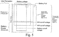
- Figure 5 depicts the battery discharging phases with respect to the actual operation states of the mobile electronic multifunctional device with respect to the battery voltage.
- the diagram depicts the different operation conditions are depicted with respect to a user perception of the MEMD.
- a user may only percept "a switched on” or “a switched off” state (independent from the actual battery voltage) and a battery charged or a batter discharged condition of the MEMD.
- the main difference between the battery charged and the battery discharged condition resides in the fact that in the battery discharged state the device cannot be switched on.
- a software cut-off when the voltage of the battery falls below a predefined threshold.
- This software cut-off usually is used to store data into persistent memories, cut-off or terminate different software application to prevent data loss, and may be accompanied by a short notification to the user that the end of battery power and battery operation is near.
- the software cut-off may be considered as the phase necessary to prepare the device for a hardware cut-off to prevent deep discharge and damage to the battery.
- connection to the battery is completely interrupted to prevent deep discharge by the last active component of the MEMD, the battery manager or battery control circuit.
- the present invention provides implementations to enable the use of an NFC component of the device even in battery voltage conditions below software (SW) cut-off (or switched off conditions) of the MEMD ( figures 2 to 4 ).
- SW software
- FIG. 2 to 4 may also be considered as a device applying individual cut-off thresholds (SW cut-off for the first functionality and hardware- (HW-) or battery cut-off) for the NFC-functionality.
- the present invention provides implementations to enable the use of an NFC component of the device under all battery voltage conditions (below SW cut-off or switched off conditions) of the MEMD ( figures 6 and 7 ).
- Figure 6 is another example of a mobile electronic multifunctional device according to an embodiment of the present invention in a normal operation condition in an NFC-Reader/Writer mode.
- the device depicted in figures 2 to 4 the device of this implementation is provided with a power management, a base-band and firmware processor, a user interface and network interface (making the MEMD a NFC enabled cellular phone).
- device is provided with a NFC chip or NFC component providing at least NFC transponder capabilities to the MEMD.
- the device is provided with a dedicated memory for storing the different configuration for the NFC component for the different operation conditions of said MEMD embodied as a NFC enabled cellular telephone.
- the MEMD As the NFC component is operated as a NFC transponder only replying to an external field, the MEMD has to be provided with RF power from an external reader to wake up the NFC components. Therefore all NFC-related components are depicted as only being powered if an external RF field is detected.
- the power management (battery control circuit), the base-band and firmware processor and the network interface are powered by the (not depicted) battery.
- the user interface maybe powered or not.
- Figure 7 depicts the mobile electronic multifunctional device of figure 6 in a phone off, hardware cut-off or battery cut-off condition.
- the device is in a phone off, hardware cut-off or battery cut-off condition that is indicated by the fact that all components like power management, the base-band and firmware processor, the network interface and the user interface are not powered. The depicted situation may occur if and when the battery has been removed from the device.
- the NFC-components may be powered by an RF field from an external NFC reader (or from any other RF source).
- the fact that the NFC components of the device may be powered by an external RF field entails a severe design restriction: as the NFC components of the device may be completely RF energy operated, the power consumption has to be restricted severely as the maximum energy that may be generated from the received RF field of an external RF reader is restricted.
- some components of the MEMD are designed as partially powerable components (such as the secure chip).
- the depicted embodiment allows to selectively powering parts of a system by external field energy alone in order to provide "battery off" functionality for end user.
- some common logic or memory is available for both, battery powered ( ⁇ phone on) and no-battery ( ⁇ phone off) situations.
- the user may control the card emulation visibility by entering respective data into the visibility mode chip. Thereby she may control to disable and enable card emulation all together, or single components of the NFC transponder/card functionality. She also may have more fine grained control over card emulation like: disable a Mifare Classic emulation function (e.g. payment card) of the NFC component and enable ISO 14443-4 level emulation function (e.g. a bus ticket) of the NFC component for each operation condition separately.
- This invention enables having the same (or different) settings in place also when the phone is without a (battery) off by providing a shared memory or firmware to drive the operation in both cases.
- the system draws all of the card emulation power from the external reader field.
- the user may select the configurations of the phone, prescribing how the card emulation should behave in each of the operation conditions. For an illustrative example about the configurable options, see the figures 8 and 9 .
- the entire phone may be in not powered state. Even the battery may be removed from the phone and the NFC-Card emulation functionality will still work.
- the key added part is a small and economical shared memory for storing the card emulation mode information.
- This shared part can be just a memory and the NFC chip takes care of interpreting the mode information in the memory.
- the shared part can also be a small processor that is able to drive the card emulation in addition to storing the mode information persistently.
- the energy budget may be extremely tight.
- the available power from external field may be around 12 mW.
- This energy level may indicate that only parts of secure chip or the visibility mode chip may be powered.
- the card emulation HW / SW should be designed so that it also has a minimum power consumption mode.
- This mode can be implemented for instance by having a secondary power supply line with low voltage and powering only the very parts that are designed to serve card emulation. For instance none of the high speed interface or network authentication features are necessary in this mode and all those parts should remain in a not powered state all the way down to the silicon level in order to match the energy budget.
- the processor is then able to wake up and execute phone software, when woken up by an "external field present" interrupt from NFC front end (as indicated in the MEMD implementation of figure 4 ).
- the processor may also execute the card emulation related code and make decision of whether the card emulation is visible to a reader (not the user) or not. It is also able to execute any other card emulation related code like SW implemented card emulation. It should not, however wake up the user interface or the cellular networking parts of the phone.
- This approach provides in many cases the means needed to fulfill for instance public transportation requirements about users being able to exit a closed gate metro system even when the phone has run out of battery.
- Figure 8 and 9 depict different implementations of user interfaces /control menus that enabling a user to select different NFC-communication component configurations for different operation conditions of the mobile electronic multifunctional device according to embodiments of the present invention.
- this dedicated control menu/user interface for terminals as user to control "visibility" of the applications residing in the secure smart card module (as an example of a NFC-communication component) for power-on (normal operation condition) and power off-situations (such as software, hardware or battery cut-off conditions).
- the user can select if the NFC-communication components of the mobile electronic device should be available in power-on and/or in the power off states (or operation/cut-off conditions). It is envisaged to implement this menu as an extension to a convention menu in which the user may select the "visibility" of the applications residing in the secure smart card module for normal operation condition (i.e. "device on”).
- Figure 9 depicts a more sophisticated implementation of the menu of figure 8 , wherein a user may select different setting of NFC-configurations for each of the different operation (or cut-off) conditions.
- This menu (of figures 8 and 9 ) is linked to a control logic that is responsible for providing necessary control over applications residing in a secure smart card module that can be attachable or alternatively an integrated module for enabling card emulation operation also in situations where the mobile terminal is not powered due to low charge in the battery, or simply because the terminal is shut down (turned off).
- an arrangement is to be provided for allowing the RFID front-end and the secure smart card module to utilize the (residual) power left in the battery in the cut-off conditions (or power off-situations) when the RFID front-end detects an external field or a NFC-communication event. Therefore, there needs to be some sort of controlling logic that takes care of the powering of suitable parts of the device when receiving a trigger signal from the RFID front-end indicating that a suitable RF field (13.56 MHz) is detected.
- This controlling unit may be implemented in the battery control circuit. This controlling circuit, then connects suitable parts of the RFID front-end and the secure smart card module for providing enough power to perform the card emulation process using the control information provided by the dedicated control menu/UI when the device was powered.
- FIG. 10 depicts a flowchart of a method according to one aspect of the present invention.
- the Flowchart starts with detecting an NFC-communication event, e.g. by detecting an RF field at an antenna of NFC-communication device.
- the current operation condition of said mobile electronic multifunctional device is determined, e.g. by detecting if the device is in a normal operation condition (i.e. "switched on"), or in a software, hardware or battery cut-off condition (wherein one of which may also be considered as device "switched off').
- a configuration of said NFC-communication component related/or allocated to said detected operation condition is determined, and said NFC-communication component of said mobile electronic multifunctional device is operated in accordance with said determined configuration of said NFC-communication component.
- the part of operating the NFC-communication component in accordance with said determined configuration may additionally comprise selectively powering parts of a system by external field energy alone in order to provide "battery cut-off' functionality for end user.
- battery powered e.g. phone on
- no-battery e.g. phone off
- the method of the present invention may also be used to completely switch the NFC-communicability off or allow only phone off NFC operability. With the present invention it is possible to selectively power parts of a system in order to provide "power off' NFC- functionality of the mobile electronic multifunctional device for end user.
- N-communication component e.g. card emulation visibility
- She should have control to disable and enable card emulation all together or separately for each operation condition of said mobile electronic multifunctional device.
- She also may have more fine grained control over card emulation like: Disable Mifare Classic emulation and enable ISO 14443-4 level emulation.
- Enable bus ticket but disable Visa card NFC-communication can also enable a user to have the same settings in place also when the phone is without a (battery) off by providing a shared memory or firmware to drive the operation in both cases.
- This application contains the description of implementations and embodiments of the present invention with the help of examples. It will be appreciated by a person skilled in the art that the present invention is not restricted to details of the embodiments presented above, and that the invention can also be implemented in another form without deviating from the scope of the claims. The embodiments presented above should be considered illustrative, but not restricting. Thus the possibilities of implementing and using the invention are only restricted by the enclosed claims. Consequently various options of implementing the invention as determined by the claims, including equivalent implementations, also belong to the scope of the invention.
Landscapes
- Engineering & Computer Science (AREA)
- Computer Networks & Wireless Communication (AREA)
- Theoretical Computer Science (AREA)
- Signal Processing (AREA)
- General Engineering & Computer Science (AREA)
- Physics & Mathematics (AREA)
- General Physics & Mathematics (AREA)
- Human Computer Interaction (AREA)
- Computer Hardware Design (AREA)
- Computing Systems (AREA)
- Telephone Function (AREA)
- Power Sources (AREA)
- Charge And Discharge Circuits For Batteries Or The Like (AREA)
- Near-Field Transmission Systems (AREA)
Priority Applications (1)
| Application Number | Priority Date | Filing Date | Title |
|---|---|---|---|
| PL06727528T PL2010988T3 (pl) | 2006-04-24 | 2006-04-24 | Układ i sposób zarządzania i sterowania komunikacją bliskiego zasięgu dla mobilnego urządzenia wielofunkcyjnego, gdy urządzenie jest nienaładowane lub tylko częściowo naładowane |
Applications Claiming Priority (1)
| Application Number | Priority Date | Filing Date | Title |
|---|---|---|---|
| PCT/IB2006/000980 WO2007122439A1 (en) | 2006-04-24 | 2006-04-24 | System and method for manage and control near field communication for a mobile multifunctional device when the device is uncharged or only partially charged |
Publications (3)
| Publication Number | Publication Date |
|---|---|
| EP2010988A1 EP2010988A1 (en) | 2009-01-07 |
| EP2010988A4 EP2010988A4 (en) | 2016-05-11 |
| EP2010988B1 true EP2010988B1 (en) | 2018-05-30 |
Family
ID=38624587
Family Applications (1)
| Application Number | Title | Priority Date | Filing Date |
|---|---|---|---|
| EP06727528.9A Active EP2010988B1 (en) | 2006-04-24 | 2006-04-24 | System and method for manage and control near field communication for a mobile multifunctional device when the device is uncharged or only partially charged |
Country Status (10)
| Country | Link |
|---|---|
| US (1) | US9762715B2 (pl) |
| EP (1) | EP2010988B1 (pl) |
| JP (2) | JP2009534771A (pl) |
| KR (1) | KR101030781B1 (pl) |
| CN (1) | CN101427197B (pl) |
| CA (1) | CA2642468C (pl) |
| ES (1) | ES2676623T3 (pl) |
| PL (1) | PL2010988T3 (pl) |
| SG (1) | SG171610A1 (pl) |
| WO (1) | WO2007122439A1 (pl) |
Families Citing this family (257)
| Publication number | Priority date | Publication date | Assignee | Title |
|---|---|---|---|---|
| US8127984B2 (en) * | 2003-06-13 | 2012-03-06 | Varia Holdings Llc | Emulated radio frequency identification |
| US20080314395A1 (en) | 2005-08-31 | 2008-12-25 | Theuniversity Of Virginia Patent Foundation | Accuracy of Continuous Glucose Sensors |
| FR2892212A1 (fr) * | 2005-10-17 | 2007-04-20 | St Microelectronics Sa | Lecteur nfc ayant un mode de fonctionnement passif a faible consommation electrique |
| US8352323B2 (en) * | 2007-11-30 | 2013-01-08 | Blaze Mobile, Inc. | Conducting an online payment transaction using an NFC enabled mobile communication device |
| DE102006060080B4 (de) * | 2006-12-19 | 2008-12-11 | Infineon Technologies Ag | Vorrichtung zum kontaktlosen Übertragen von Daten aus einem Speicher |
| KR101389448B1 (ko) * | 2007-03-27 | 2014-04-28 | 삼성전자주식회사 | 이동형 전자 장치 및 그것의 전원 관리 방법 |
| WO2009050624A2 (en) * | 2007-10-15 | 2009-04-23 | Nxp B.V. | Method of controlling a power transfer system and power transfer system |
| EP2071497A1 (fr) * | 2007-12-10 | 2009-06-17 | Gemalto SA | Procédé et dispositif chargeur de batterie sans contact |
| US7912441B2 (en) * | 2007-12-11 | 2011-03-22 | Motorola Mobility, Inc. | Apparatus and method for enabling near field communication equipment in a portable communications device |
| JP5315849B2 (ja) * | 2008-01-22 | 2013-10-16 | 株式会社リコー | 通信装置、通信方法、通信プログラム |
| EP2255340B1 (en) * | 2008-03-10 | 2019-02-20 | Nxp B.V. | Method and devices for installing and retrieving linked mifare applications |
| US8739289B2 (en) * | 2008-04-04 | 2014-05-27 | Microsoft Corporation | Hardware interface for enabling direct access and security assessment sharing |
| CN101291494B (zh) * | 2008-04-24 | 2012-04-18 | 中兴通讯股份有限公司 | 一种实现移动终端同用户绑定的方法 |
| KR101532573B1 (ko) | 2008-08-22 | 2015-06-30 | 엘지전자 주식회사 | 휴대 단말기 및 그 제어방법 |
| EP2211480B1 (en) * | 2009-01-26 | 2013-10-23 | Motorola Mobility LLC | Wireless communication device for providing at least one near field communication service |
| KR101002530B1 (ko) * | 2009-02-18 | 2010-12-17 | 삼성에스디아이 주식회사 | 알에프아이디 통신 장치 |
| EP2224375B1 (en) * | 2009-02-25 | 2018-11-14 | Vodafone Holding GmbH | Power supply for a system including chip card connected to a host device |
| CN101820696B (zh) | 2009-02-26 | 2013-08-07 | 中兴通讯股份有限公司 | 支持增强型近场通信的终端及其处理方法 |
| US8428513B2 (en) * | 2009-03-27 | 2013-04-23 | Motorola Mobility Llc | Methods, systems and apparatus for selecting an application in power-off mode |
| KR100911032B1 (ko) | 2009-04-01 | 2009-08-05 | (주)애니쿼터스 | Nfc 칩 모듈과 외부 rf 리더기를 통한 휴대폰 단말기의 벨소리·카메라·통신기능을 제어하는 장치 및 방법 |
| TWM366130U (en) * | 2009-05-27 | 2009-10-01 | Phytrex Technology Corp | Dual-chip signal converter |
| JP2011060169A (ja) * | 2009-09-14 | 2011-03-24 | Ricoh Co Ltd | 携帯通信端末、ホスト通信装置及びrfidシステム |
| US8670709B2 (en) * | 2010-02-26 | 2014-03-11 | Blackberry Limited | Near-field communication (NFC) system providing mobile wireless communications device operations based upon timing and sequence of NFC sensor communication and related methods |
| US8526880B2 (en) * | 2010-02-26 | 2013-09-03 | Blackberry Limited | Communications device responsive to near field communications (NFC) to enter locked or unlocked operating modes |
| CN101826895A (zh) * | 2010-03-12 | 2010-09-08 | 东莞宇龙通信科技有限公司 | 一种基于nfc的数据获取方法、nfc电子终端和系统 |
| CN101894290B (zh) * | 2010-04-06 | 2015-07-08 | 上海复旦微电子集团股份有限公司 | 非接触通信装置 |
| US8718546B2 (en) * | 2010-08-16 | 2014-05-06 | Blackberry Limited | Near-field communication (NFC) system providing low power peer-to-peer recognition mode and related methods |
| US8068011B1 (en) | 2010-08-27 | 2011-11-29 | Q Street, LLC | System and method for interactive user-directed interfacing between handheld devices and RFID media |
| US9030052B2 (en) | 2011-05-17 | 2015-05-12 | Samsung Electronics Co., Ltd. | Apparatus and method for using near field communication and wireless power transmission |
| US8548380B2 (en) * | 2011-06-10 | 2013-10-01 | Broadcom Corporation | Communications device for intelligently routing information among multiple user interfaces |
| US8879985B2 (en) | 2011-06-28 | 2014-11-04 | Broadcom Corporation | Memory arbitrator for electronics communications devices |
| US8620218B2 (en) | 2011-06-29 | 2013-12-31 | Broadcom Corporation | Power harvesting and use in a near field communications (NFC) device |
| US9026047B2 (en) * | 2011-06-29 | 2015-05-05 | Broadcom Corporation | Systems and methods for providing NFC secure application support in battery-off mode when no nonvolatile memory write access is available |
| US9307495B2 (en) * | 2011-09-12 | 2016-04-05 | Apple Inc. | Monitoring a battery in a portable electronic device |
| CN102316226B (zh) * | 2011-09-23 | 2013-12-11 | 惠州Tcl移动通信有限公司 | 一种nfc移动终端 |
| US9384373B2 (en) * | 2011-10-26 | 2016-07-05 | Qualcomm Incorporated | Adaptive signal scaling in NFC transceivers |
| KR101932519B1 (ko) * | 2011-11-14 | 2018-12-27 | 삼성전자 주식회사 | 휴대 단말기의 근접 인터페이스 커플링 카드 선택 방법 및 장치 |
| US10020847B2 (en) * | 2011-11-15 | 2018-07-10 | Famoco | NFC device and connection system of NFC devices |
| US9064253B2 (en) * | 2011-12-01 | 2015-06-23 | Broadcom Corporation | Systems and methods for providing NFC secure application support in battery on and battery off modes |
| EP2629499B1 (en) * | 2012-02-15 | 2014-08-27 | ST-Ericsson SA | Battery management scheme for NFC |
| WO2013127521A1 (de) | 2012-02-28 | 2013-09-06 | Giesecke & Devrient Gmbh | Verfahren zur computer-zugangskontrolle mittels mobilem endgerät |
| US8690412B2 (en) * | 2012-03-15 | 2014-04-08 | Apple Inc. | Backlight structures and backlight assemblies for electronic device displays |
| KR101984970B1 (ko) * | 2012-06-07 | 2019-09-03 | 삼성전자주식회사 | 근거리 무선 통신 장치 및 이를 포함하는 전자 장치의 전력 관리 방법 |
| US10224982B1 (en) | 2013-07-11 | 2019-03-05 | Energous Corporation | Wireless power transmitters for transmitting wireless power and tracking whether wireless power receivers are within authorized locations |
| US9899873B2 (en) | 2014-05-23 | 2018-02-20 | Energous Corporation | System and method for generating a power receiver identifier in a wireless power network |
| US10218227B2 (en) | 2014-05-07 | 2019-02-26 | Energous Corporation | Compact PIFA antenna |
| US9906065B2 (en) | 2012-07-06 | 2018-02-27 | Energous Corporation | Systems and methods of transmitting power transmission waves based on signals received at first and second subsets of a transmitter's antenna array |
| US9876394B1 (en) | 2014-05-07 | 2018-01-23 | Energous Corporation | Boost-charger-boost system for enhanced power delivery |
| US10270261B2 (en) | 2015-09-16 | 2019-04-23 | Energous Corporation | Systems and methods of object detection in wireless power charging systems |
| US9887584B1 (en) | 2014-08-21 | 2018-02-06 | Energous Corporation | Systems and methods for a configuration web service to provide configuration of a wireless power transmitter within a wireless power transmission system |
| US9991741B1 (en) | 2014-07-14 | 2018-06-05 | Energous Corporation | System for tracking and reporting status and usage information in a wireless power management system |
| US9954374B1 (en) | 2014-05-23 | 2018-04-24 | Energous Corporation | System and method for self-system analysis for detecting a fault in a wireless power transmission Network |
| US9882430B1 (en) | 2014-05-07 | 2018-01-30 | Energous Corporation | Cluster management of transmitters in a wireless power transmission system |
| US9847679B2 (en) | 2014-05-07 | 2017-12-19 | Energous Corporation | System and method for controlling communication between wireless power transmitter managers |
| US10291066B1 (en) | 2014-05-07 | 2019-05-14 | Energous Corporation | Power transmission control systems and methods |
| US10381880B2 (en) | 2014-07-21 | 2019-08-13 | Energous Corporation | Integrated antenna structure arrays for wireless power transmission |
| US10263432B1 (en) | 2013-06-25 | 2019-04-16 | Energous Corporation | Multi-mode transmitter with an antenna array for delivering wireless power and providing Wi-Fi access |
| US10124754B1 (en) | 2013-07-19 | 2018-11-13 | Energous Corporation | Wireless charging and powering of electronic sensors in a vehicle |
| US10141768B2 (en) | 2013-06-03 | 2018-11-27 | Energous Corporation | Systems and methods for maximizing wireless power transfer efficiency by instructing a user to change a receiver device's position |
| US9124125B2 (en) | 2013-05-10 | 2015-09-01 | Energous Corporation | Wireless power transmission with selective range |
| US9806564B2 (en) | 2014-05-07 | 2017-10-31 | Energous Corporation | Integrated rectifier and boost converter for wireless power transmission |
| US10090886B1 (en) | 2014-07-14 | 2018-10-02 | Energous Corporation | System and method for enabling automatic charging schedules in a wireless power network to one or more devices |
| US10992187B2 (en) | 2012-07-06 | 2021-04-27 | Energous Corporation | System and methods of using electromagnetic waves to wirelessly deliver power to electronic devices |
| US10992185B2 (en) | 2012-07-06 | 2021-04-27 | Energous Corporation | Systems and methods of using electromagnetic waves to wirelessly deliver power to game controllers |
| US9893554B2 (en) | 2014-07-14 | 2018-02-13 | Energous Corporation | System and method for providing health safety in a wireless power transmission system |
| US9859756B2 (en) | 2012-07-06 | 2018-01-02 | Energous Corporation | Transmittersand methods for adjusting wireless power transmission based on information from receivers |
| US9787103B1 (en) | 2013-08-06 | 2017-10-10 | Energous Corporation | Systems and methods for wirelessly delivering power to electronic devices that are unable to communicate with a transmitter |
| US9825674B1 (en) | 2014-05-23 | 2017-11-21 | Energous Corporation | Enhanced transmitter that selects configurations of antenna elements for performing wireless power transmission and receiving functions |
| US9973021B2 (en) | 2012-07-06 | 2018-05-15 | Energous Corporation | Receivers for wireless power transmission |
| US9853692B1 (en) | 2014-05-23 | 2017-12-26 | Energous Corporation | Systems and methods for wireless power transmission |
| US9891669B2 (en) | 2014-08-21 | 2018-02-13 | Energous Corporation | Systems and methods for a configuration web service to provide configuration of a wireless power transmitter within a wireless power transmission system |
| US10211682B2 (en) | 2014-05-07 | 2019-02-19 | Energous Corporation | Systems and methods for controlling operation of a transmitter of a wireless power network based on user instructions received from an authenticated computing device powered or charged by a receiver of the wireless power network |
| US10199835B2 (en) | 2015-12-29 | 2019-02-05 | Energous Corporation | Radar motion detection using stepped frequency in wireless power transmission system |
| US10230266B1 (en) | 2014-02-06 | 2019-03-12 | Energous Corporation | Wireless power receivers that communicate status data indicating wireless power transmission effectiveness with a transmitter using a built-in communications component of a mobile device, and methods of use thereof |
| US9899861B1 (en) | 2013-10-10 | 2018-02-20 | Energous Corporation | Wireless charging methods and systems for game controllers, based on pocket-forming |
| US9876648B2 (en) | 2014-08-21 | 2018-01-23 | Energous Corporation | System and method to control a wireless power transmission system by configuration of wireless power transmission control parameters |
| US10199849B1 (en) | 2014-08-21 | 2019-02-05 | Energous Corporation | Method for automatically testing the operational status of a wireless power receiver in a wireless power transmission system |
| US10205239B1 (en) | 2014-05-07 | 2019-02-12 | Energous Corporation | Compact PIFA antenna |
| US10063064B1 (en) | 2014-05-23 | 2018-08-28 | Energous Corporation | System and method for generating a power receiver identifier in a wireless power network |
| US10224758B2 (en) | 2013-05-10 | 2019-03-05 | Energous Corporation | Wireless powering of electronic devices with selective delivery range |
| US9893555B1 (en) | 2013-10-10 | 2018-02-13 | Energous Corporation | Wireless charging of tools using a toolbox transmitter |
| US9438045B1 (en) | 2013-05-10 | 2016-09-06 | Energous Corporation | Methods and systems for maximum power point transfer in receivers |
| US10243414B1 (en) | 2014-05-07 | 2019-03-26 | Energous Corporation | Wearable device with wireless power and payload receiver |
| US10256657B2 (en) | 2015-12-24 | 2019-04-09 | Energous Corporation | Antenna having coaxial structure for near field wireless power charging |
| US10291055B1 (en) | 2014-12-29 | 2019-05-14 | Energous Corporation | Systems and methods for controlling far-field wireless power transmission based on battery power levels of a receiving device |
| US9893768B2 (en) | 2012-07-06 | 2018-02-13 | Energous Corporation | Methodology for multiple pocket-forming |
| US10223717B1 (en) | 2014-05-23 | 2019-03-05 | Energous Corporation | Systems and methods for payment-based authorization of wireless power transmission service |
| US10063106B2 (en) | 2014-05-23 | 2018-08-28 | Energous Corporation | System and method for a self-system analysis in a wireless power transmission network |
| US10211674B1 (en) | 2013-06-12 | 2019-02-19 | Energous Corporation | Wireless charging using selected reflectors |
| US9912199B2 (en) | 2012-07-06 | 2018-03-06 | Energous Corporation | Receivers for wireless power transmission |
| US9948135B2 (en) | 2015-09-22 | 2018-04-17 | Energous Corporation | Systems and methods for identifying sensitive objects in a wireless charging transmission field |
| US9793758B2 (en) | 2014-05-23 | 2017-10-17 | Energous Corporation | Enhanced transmitter using frequency control for wireless power transmission |
| US10141791B2 (en) | 2014-05-07 | 2018-11-27 | Energous Corporation | Systems and methods for controlling communications during wireless transmission of power using application programming interfaces |
| US10090699B1 (en) | 2013-11-01 | 2018-10-02 | Energous Corporation | Wireless powered house |
| US9939864B1 (en) | 2014-08-21 | 2018-04-10 | Energous Corporation | System and method to control a wireless power transmission system by configuration of wireless power transmission control parameters |
| US10211680B2 (en) | 2013-07-19 | 2019-02-19 | Energous Corporation | Method for 3 dimensional pocket-forming |
| US9838083B2 (en) | 2014-07-21 | 2017-12-05 | Energous Corporation | Systems and methods for communication with remote management systems |
| US9871398B1 (en) | 2013-07-01 | 2018-01-16 | Energous Corporation | Hybrid charging method for wireless power transmission based on pocket-forming |
| US9900057B2 (en) | 2012-07-06 | 2018-02-20 | Energous Corporation | Systems and methods for assigning groups of antenas of a wireless power transmitter to different wireless power receivers, and determining effective phases to use for wirelessly transmitting power using the assigned groups of antennas |
| US9887739B2 (en) | 2012-07-06 | 2018-02-06 | Energous Corporation | Systems and methods for wireless power transmission by comparing voltage levels associated with power waves transmitted by antennas of a plurality of antennas of a transmitter to determine appropriate phase adjustments for the power waves |
| US10038337B1 (en) | 2013-09-16 | 2018-07-31 | Energous Corporation | Wireless power supply for rescue devices |
| US20150326070A1 (en) | 2014-05-07 | 2015-11-12 | Energous Corporation | Methods and Systems for Maximum Power Point Transfer in Receivers |
| US9252628B2 (en) | 2013-05-10 | 2016-02-02 | Energous Corporation | Laptop computer as a transmitter for wireless charging |
| US9368020B1 (en) | 2013-05-10 | 2016-06-14 | Energous Corporation | Off-premises alert system and method for wireless power receivers in a wireless power network |
| US10128693B2 (en) | 2014-07-14 | 2018-11-13 | Energous Corporation | System and method for providing health safety in a wireless power transmission system |
| US10063105B2 (en) | 2013-07-11 | 2018-08-28 | Energous Corporation | Proximity transmitters for wireless power charging systems |
| US10128699B2 (en) | 2014-07-14 | 2018-11-13 | Energous Corporation | Systems and methods of providing wireless power using receiver device sensor inputs |
| US9843213B2 (en) | 2013-08-06 | 2017-12-12 | Energous Corporation | Social power sharing for mobile devices based on pocket-forming |
| US9941707B1 (en) | 2013-07-19 | 2018-04-10 | Energous Corporation | Home base station for multiple room coverage with multiple transmitters |
| US10193396B1 (en) | 2014-05-07 | 2019-01-29 | Energous Corporation | Cluster management of transmitters in a wireless power transmission system |
| US10008889B2 (en) | 2014-08-21 | 2018-06-26 | Energous Corporation | Method for automatically testing the operational status of a wireless power receiver in a wireless power transmission system |
| US9966765B1 (en) | 2013-06-25 | 2018-05-08 | Energous Corporation | Multi-mode transmitter |
| US9867062B1 (en) | 2014-07-21 | 2018-01-09 | Energous Corporation | System and methods for using a remote server to authorize a receiving device that has requested wireless power and to determine whether another receiving device should request wireless power in a wireless power transmission system |
| US9941747B2 (en) * | 2014-07-14 | 2018-04-10 | Energous Corporation | System and method for manually selecting and deselecting devices to charge in a wireless power network |
| US9859797B1 (en) | 2014-05-07 | 2018-01-02 | Energous Corporation | Synchronous rectifier design for wireless power receiver |
| US9812890B1 (en) | 2013-07-11 | 2017-11-07 | Energous Corporation | Portable wireless charging pad |
| US9882427B2 (en) | 2013-05-10 | 2018-01-30 | Energous Corporation | Wireless power delivery using a base station to control operations of a plurality of wireless power transmitters |
| US10965164B2 (en) | 2012-07-06 | 2021-03-30 | Energous Corporation | Systems and methods of wirelessly delivering power to a receiver device |
| US10050462B1 (en) | 2013-08-06 | 2018-08-14 | Energous Corporation | Social power sharing for mobile devices based on pocket-forming |
| US9853458B1 (en) | 2014-05-07 | 2017-12-26 | Energous Corporation | Systems and methods for device and power receiver pairing |
| US10075008B1 (en) | 2014-07-14 | 2018-09-11 | Energous Corporation | Systems and methods for manually adjusting when receiving electronic devices are scheduled to receive wirelessly delivered power from a wireless power transmitter in a wireless power network |
| US10206185B2 (en) | 2013-05-10 | 2019-02-12 | Energous Corporation | System and methods for wireless power transmission to an electronic device in accordance with user-defined restrictions |
| US9143000B2 (en) | 2012-07-06 | 2015-09-22 | Energous Corporation | Portable wireless charging pad |
| US10148097B1 (en) | 2013-11-08 | 2018-12-04 | Energous Corporation | Systems and methods for using a predetermined number of communication channels of a wireless power transmitter to communicate with different wireless power receivers |
| US9876379B1 (en) | 2013-07-11 | 2018-01-23 | Energous Corporation | Wireless charging and powering of electronic devices in a vehicle |
| US9923386B1 (en) | 2012-07-06 | 2018-03-20 | Energous Corporation | Systems and methods for wireless power transmission by modifying a number of antenna elements used to transmit power waves to a receiver |
| US20140008993A1 (en) | 2012-07-06 | 2014-01-09 | DvineWave Inc. | Methodology for pocket-forming |
| US9859757B1 (en) | 2013-07-25 | 2018-01-02 | Energous Corporation | Antenna tile arrangements in electronic device enclosures |
| US9843201B1 (en) | 2012-07-06 | 2017-12-12 | Energous Corporation | Wireless power transmitter that selects antenna sets for transmitting wireless power to a receiver based on location of the receiver, and methods of use thereof |
| US10312715B2 (en) | 2015-09-16 | 2019-06-04 | Energous Corporation | Systems and methods for wireless power charging |
| US9824815B2 (en) | 2013-05-10 | 2017-11-21 | Energous Corporation | Wireless charging and powering of healthcare gadgets and sensors |
| US10103582B2 (en) | 2012-07-06 | 2018-10-16 | Energous Corporation | Transmitters for wireless power transmission |
| US9941754B2 (en) | 2012-07-06 | 2018-04-10 | Energous Corporation | Wireless power transmission with selective range |
| US9831718B2 (en) | 2013-07-25 | 2017-11-28 | Energous Corporation | TV with integrated wireless power transmitter |
| US10186913B2 (en) | 2012-07-06 | 2019-01-22 | Energous Corporation | System and methods for pocket-forming based on constructive and destructive interferences to power one or more wireless power receivers using a wireless power transmitter including a plurality of antennas |
| US11502551B2 (en) | 2012-07-06 | 2022-11-15 | Energous Corporation | Wirelessly charging multiple wireless-power receivers using different subsets of an antenna array to focus energy at different locations |
| US10439448B2 (en) | 2014-08-21 | 2019-10-08 | Energous Corporation | Systems and methods for automatically testing the communication between wireless power transmitter and wireless power receiver |
| US9847677B1 (en) | 2013-10-10 | 2017-12-19 | Energous Corporation | Wireless charging and powering of healthcare gadgets and sensors |
| EP2901153A4 (en) | 2012-09-26 | 2016-04-27 | Abbott Diabetes Care Inc | METHOD AND DEVICE FOR IMPROVING DELAY CORRECTION FUNCTION DURING IN VIVO MEASUREMENT OF ANALYZ CONCENTRATION WITH ANALYZ CONCENTRATION VARIABILITY AND RANGE DATA |
| JP6043612B2 (ja) * | 2012-12-11 | 2016-12-14 | 太平洋工業株式会社 | タイヤ状態監視装置 |
| US9730621B2 (en) | 2012-12-31 | 2017-08-15 | Dexcom, Inc. | Remote monitoring of analyte measurements |
| US9801541B2 (en) | 2012-12-31 | 2017-10-31 | Dexcom, Inc. | Remote monitoring of analyte measurements |
| US9159013B2 (en) | 2013-01-04 | 2015-10-13 | Google Technology Holdings LLC | Mobile device with RFID capability and corresponding boot sequence |
| FR3002664B1 (fr) * | 2013-02-26 | 2016-12-30 | Hikob | Dispositif electronique autonome a memoire tampon nfc et procede de pilotage de ce dispositif electronique |
| US9445445B2 (en) | 2013-03-14 | 2016-09-13 | Dexcom, Inc. | Systems and methods for processing and transmitting sensor data |
| US9931036B2 (en) | 2013-03-14 | 2018-04-03 | Dexcom, Inc. | Systems and methods for processing and transmitting sensor data |
| EP4220654A1 (en) * | 2013-03-14 | 2023-08-02 | Dexcom, Inc. | Systems and methods for processing and transmitting sensor data |
| US9866279B2 (en) | 2013-05-10 | 2018-01-09 | Energous Corporation | Systems and methods for selecting which power transmitter should deliver wireless power to a receiving device in a wireless power delivery network |
| US9843763B2 (en) | 2013-05-10 | 2017-12-12 | Energous Corporation | TV system with wireless power transmitter |
| US9537357B2 (en) | 2013-05-10 | 2017-01-03 | Energous Corporation | Wireless sound charging methods and systems for game controllers, based on pocket-forming |
| US9819230B2 (en) | 2014-05-07 | 2017-11-14 | Energous Corporation | Enhanced receiver for wireless power transmission |
| US9538382B2 (en) | 2013-05-10 | 2017-01-03 | Energous Corporation | System and method for smart registration of wireless power receivers in a wireless power network |
| US9419443B2 (en) | 2013-05-10 | 2016-08-16 | Energous Corporation | Transducer sound arrangement for pocket-forming |
| JP6239864B2 (ja) * | 2013-05-20 | 2017-11-29 | キヤノン株式会社 | 通信装置及びその制御方法、並びにプログラム |
| US10103552B1 (en) | 2013-06-03 | 2018-10-16 | Energous Corporation | Protocols for authenticated wireless power transmission |
| US10003211B1 (en) | 2013-06-17 | 2018-06-19 | Energous Corporation | Battery life of portable electronic devices |
| US10021523B2 (en) | 2013-07-11 | 2018-07-10 | Energous Corporation | Proximity transmitters for wireless power charging systems |
| US9979440B1 (en) | 2013-07-25 | 2018-05-22 | Energous Corporation | Antenna tile arrangements configured to operate as one functional unit |
| US11556915B2 (en) | 2013-08-08 | 2023-01-17 | Apple Inc. | Low power mode for payment transactions |
| US9603090B2 (en) | 2013-08-08 | 2017-03-21 | Apple Inc. | Management of near field communications using low power modes of an electronic device |
| US10198726B2 (en) | 2013-08-08 | 2019-02-05 | Apple Inc. | Low power mode for payment transactions |
| US9774209B2 (en) * | 2013-10-03 | 2017-09-26 | Avago Technologies General Ip (Singapore) Pte. | Selective power distribution during wireless charging |
| CN105659513A (zh) * | 2013-10-29 | 2016-06-08 | 京瓷株式会社 | 电子设备 |
| US9473908B2 (en) | 2013-11-12 | 2016-10-18 | Motorola Solutions, Inc. | Method and apparatus for a remote speaker microphone to indicate radio battery charge state with flashlight and strobe control |
| US9935482B1 (en) | 2014-02-06 | 2018-04-03 | Energous Corporation | Wireless power transmitters that transmit at determined times based on power availability and consumption at a receiving mobile device |
| US10075017B2 (en) | 2014-02-06 | 2018-09-11 | Energous Corporation | External or internal wireless power receiver with spaced-apart antenna elements for charging or powering mobile devices using wirelessly delivered power |
| US20150268713A1 (en) * | 2014-03-24 | 2015-09-24 | Advanced Micro Devices, Inc. | Energy-aware boosting of processor operating points for limited duration workloads |
| US9966784B2 (en) | 2014-06-03 | 2018-05-08 | Energous Corporation | Systems and methods for extending battery life of portable electronic devices charged by sound |
| US10158257B2 (en) | 2014-05-01 | 2018-12-18 | Energous Corporation | System and methods for using sound waves to wirelessly deliver power to electronic devices |
| US10170917B1 (en) | 2014-05-07 | 2019-01-01 | Energous Corporation | Systems and methods for managing and controlling a wireless power network by establishing time intervals during which receivers communicate with a transmitter |
| US9800172B1 (en) | 2014-05-07 | 2017-10-24 | Energous Corporation | Integrated rectifier and boost converter for boosting voltage received from wireless power transmission waves |
| US10153645B1 (en) | 2014-05-07 | 2018-12-11 | Energous Corporation | Systems and methods for designating a master power transmitter in a cluster of wireless power transmitters |
| US9973008B1 (en) | 2014-05-07 | 2018-05-15 | Energous Corporation | Wireless power receiver with boost converters directly coupled to a storage element |
| US10153653B1 (en) | 2014-05-07 | 2018-12-11 | Energous Corporation | Systems and methods for using application programming interfaces to control communications between a transmitter and a receiver |
| US9876536B1 (en) | 2014-05-23 | 2018-01-23 | Energous Corporation | Systems and methods for assigning groups of antennas to transmit wireless power to different wireless power receivers |
| US9426748B2 (en) * | 2014-07-11 | 2016-08-23 | Qualcomm Incorporated | Dynamic sleep mode based upon battery charge |
| US10116143B1 (en) | 2014-07-21 | 2018-10-30 | Energous Corporation | Integrated antenna arrays for wireless power transmission |
| US10068703B1 (en) | 2014-07-21 | 2018-09-04 | Energous Corporation | Integrated miniature PIFA with artificial magnetic conductor metamaterials |
| US9871301B2 (en) | 2014-07-21 | 2018-01-16 | Energous Corporation | Integrated miniature PIFA with artificial magnetic conductor metamaterials |
| US9965009B1 (en) | 2014-08-21 | 2018-05-08 | Energous Corporation | Systems and methods for assigning a power receiver to individual power transmitters based on location of the power receiver |
| US9917477B1 (en) | 2014-08-21 | 2018-03-13 | Energous Corporation | Systems and methods for automatically testing the communication between power transmitter and wireless receiver |
| JP6438245B2 (ja) * | 2014-09-05 | 2018-12-12 | キヤノン株式会社 | 通信装置およびその制御方法、プログラム |
| FR3029324B1 (fr) * | 2014-11-28 | 2017-12-15 | Proton World Int Nv | Acces a des donnees dans un dispositif mobile nfc |
| US10122415B2 (en) | 2014-12-27 | 2018-11-06 | Energous Corporation | Systems and methods for assigning a set of antennas of a wireless power transmitter to a wireless power receiver based on a location of the wireless power receiver |
| US9893535B2 (en) | 2015-02-13 | 2018-02-13 | Energous Corporation | Systems and methods for determining optimal charging positions to maximize efficiency of power received from wirelessly delivered sound wave energy |
| US10162347B2 (en) * | 2015-04-20 | 2018-12-25 | Lg Electronics Inc. | Mobile terminal and method for controlling the same |
| US10523033B2 (en) | 2015-09-15 | 2019-12-31 | Energous Corporation | Receiver devices configured to determine location within a transmission field |
| US9906275B2 (en) | 2015-09-15 | 2018-02-27 | Energous Corporation | Identifying receivers in a wireless charging transmission field |
| US10211685B2 (en) | 2015-09-16 | 2019-02-19 | Energous Corporation | Systems and methods for real or near real time wireless communications between a wireless power transmitter and a wireless power receiver |
| US11710321B2 (en) | 2015-09-16 | 2023-07-25 | Energous Corporation | Systems and methods of object detection in wireless power charging systems |
| US9893538B1 (en) | 2015-09-16 | 2018-02-13 | Energous Corporation | Systems and methods of object detection in wireless power charging systems |
| US10778041B2 (en) | 2015-09-16 | 2020-09-15 | Energous Corporation | Systems and methods for generating power waves in a wireless power transmission system |
| US10199850B2 (en) | 2015-09-16 | 2019-02-05 | Energous Corporation | Systems and methods for wirelessly transmitting power from a transmitter to a receiver by determining refined locations of the receiver in a segmented transmission field associated with the transmitter |
| US10008875B1 (en) | 2015-09-16 | 2018-06-26 | Energous Corporation | Wireless power transmitter configured to transmit power waves to a predicted location of a moving wireless power receiver |
| US9871387B1 (en) | 2015-09-16 | 2018-01-16 | Energous Corporation | Systems and methods of object detection using one or more video cameras in wireless power charging systems |
| US9941752B2 (en) | 2015-09-16 | 2018-04-10 | Energous Corporation | Systems and methods of object detection in wireless power charging systems |
| US10186893B2 (en) | 2015-09-16 | 2019-01-22 | Energous Corporation | Systems and methods for real time or near real time wireless communications between a wireless power transmitter and a wireless power receiver |
| US10158259B1 (en) | 2015-09-16 | 2018-12-18 | Energous Corporation | Systems and methods for identifying receivers in a transmission field by transmitting exploratory power waves towards different segments of a transmission field |
| US10135294B1 (en) | 2015-09-22 | 2018-11-20 | Energous Corporation | Systems and methods for preconfiguring transmission devices for power wave transmissions based on location data of one or more receivers |
| US10128686B1 (en) | 2015-09-22 | 2018-11-13 | Energous Corporation | Systems and methods for identifying receiver locations using sensor technologies |
| US10153660B1 (en) | 2015-09-22 | 2018-12-11 | Energous Corporation | Systems and methods for preconfiguring sensor data for wireless charging systems |
| US10020678B1 (en) | 2015-09-22 | 2018-07-10 | Energous Corporation | Systems and methods for selecting antennas to generate and transmit power transmission waves |
| US10027168B2 (en) | 2015-09-22 | 2018-07-17 | Energous Corporation | Systems and methods for generating and transmitting wireless power transmission waves using antennas having a spacing that is selected by the transmitter |
| US10033222B1 (en) | 2015-09-22 | 2018-07-24 | Energous Corporation | Systems and methods for determining and generating a waveform for wireless power transmission waves |
| US10135295B2 (en) | 2015-09-22 | 2018-11-20 | Energous Corporation | Systems and methods for nullifying energy levels for wireless power transmission waves |
| US10050470B1 (en) | 2015-09-22 | 2018-08-14 | Energous Corporation | Wireless power transmission device having antennas oriented in three dimensions |
| US10333332B1 (en) | 2015-10-13 | 2019-06-25 | Energous Corporation | Cross-polarized dipole antenna |
| US10734717B2 (en) | 2015-10-13 | 2020-08-04 | Energous Corporation | 3D ceramic mold antenna |
| US9853485B2 (en) | 2015-10-28 | 2017-12-26 | Energous Corporation | Antenna for wireless charging systems |
| US9899744B1 (en) | 2015-10-28 | 2018-02-20 | Energous Corporation | Antenna for wireless charging systems |
| US10135112B1 (en) | 2015-11-02 | 2018-11-20 | Energous Corporation | 3D antenna mount |
| US10063108B1 (en) | 2015-11-02 | 2018-08-28 | Energous Corporation | Stamped three-dimensional antenna |
| US10027180B1 (en) | 2015-11-02 | 2018-07-17 | Energous Corporation | 3D triple linear antenna that acts as heat sink |
| JP6727798B2 (ja) | 2015-12-07 | 2020-07-22 | キヤノン株式会社 | 情報処理装置及びその制御方法、並びにプログラム |
| US10320446B2 (en) | 2015-12-24 | 2019-06-11 | Energous Corporation | Miniaturized highly-efficient designs for near-field power transfer system |
| US10256677B2 (en) | 2016-12-12 | 2019-04-09 | Energous Corporation | Near-field RF charging pad with adaptive loading to efficiently charge an electronic device at any position on the pad |
| US10218207B2 (en) | 2015-12-24 | 2019-02-26 | Energous Corporation | Receiver chip for routing a wireless signal for wireless power charging or data reception |
| US10079515B2 (en) | 2016-12-12 | 2018-09-18 | Energous Corporation | Near-field RF charging pad with multi-band antenna element with adaptive loading to efficiently charge an electronic device at any position on the pad |
| US10038332B1 (en) | 2015-12-24 | 2018-07-31 | Energous Corporation | Systems and methods of wireless power charging through multiple receiving devices |
| US10027159B2 (en) | 2015-12-24 | 2018-07-17 | Energous Corporation | Antenna for transmitting wireless power signals |
| US11863001B2 (en) | 2015-12-24 | 2024-01-02 | Energous Corporation | Near-field antenna for wireless power transmission with antenna elements that follow meandering patterns |
| US20170181645A1 (en) | 2015-12-28 | 2017-06-29 | Dexcom, Inc. | Systems and methods for remote and host monitoring communications |
| US10008886B2 (en) | 2015-12-29 | 2018-06-26 | Energous Corporation | Modular antennas with heat sinks in wireless power transmission systems |
| EP3797685B8 (en) | 2016-03-31 | 2022-06-15 | Dexcom, Inc. | Communication systems between a sensor electronics unit and a display device of an analyte monitoring system |
| US10923954B2 (en) | 2016-11-03 | 2021-02-16 | Energous Corporation | Wireless power receiver with a synchronous rectifier |
| JP6691273B2 (ja) | 2016-12-12 | 2020-04-28 | エナージャス コーポレイション | 配送される無線電力を最大化するために近接場充電パッドのアンテナ区域を選択的に活性化する方法 |
| US10389161B2 (en) | 2017-03-15 | 2019-08-20 | Energous Corporation | Surface mount dielectric antennas for wireless power transmitters |
| US10680319B2 (en) | 2017-01-06 | 2020-06-09 | Energous Corporation | Devices and methods for reducing mutual coupling effects in wireless power transmission systems |
| US10439442B2 (en) | 2017-01-24 | 2019-10-08 | Energous Corporation | Microstrip antennas for wireless power transmitters |
| WO2018183892A1 (en) | 2017-03-30 | 2018-10-04 | Energous Corporation | Flat antennas having two or more resonant frequencies for use in wireless power transmission systems |
| US10511097B2 (en) | 2017-05-12 | 2019-12-17 | Energous Corporation | Near-field antennas for accumulating energy at a near-field distance with minimal far-field gain |
| US11462949B2 (en) | 2017-05-16 | 2022-10-04 | Wireless electrical Grid LAN, WiGL Inc | Wireless charging method and system |
| FR3067534A1 (fr) * | 2017-06-09 | 2018-12-14 | Stmicroelectronics (Rousset) Sas | Procede de controle du niveau de puissance emise par un dispositif de communication sans contact, par exemple un lecteur, et dispositif de communication sans contact correspondant |
| US10848853B2 (en) | 2017-06-23 | 2020-11-24 | Energous Corporation | Systems, methods, and devices for utilizing a wire of a sound-producing device as an antenna for receipt of wirelessly delivered power |
| US10389410B2 (en) | 2017-06-29 | 2019-08-20 | Texas Instruments Incorporated | Integrated artificial magnetic launch surface for near field communication system |
| US10425793B2 (en) | 2017-06-29 | 2019-09-24 | Texas Instruments Incorporated | Staggered back-to-back launch topology with diagonal waveguides for field confined near field communication system |
| US10461810B2 (en) | 2017-06-29 | 2019-10-29 | Texas Instruments Incorporated | Launch topology for field confined near field communication system |
| US10623063B2 (en) * | 2017-07-18 | 2020-04-14 | Texas Instruments Incorporated | Backplane with near field coupling to modules |
| US10122219B1 (en) | 2017-10-10 | 2018-11-06 | Energous Corporation | Systems, methods, and devices for using a battery as a antenna for receiving wirelessly delivered power from radio frequency power waves |
| US11342798B2 (en) | 2017-10-30 | 2022-05-24 | Energous Corporation | Systems and methods for managing coexistence of wireless-power signals and data signals operating in a same frequency band |
| CN107862226A (zh) | 2017-11-10 | 2018-03-30 | 阿里巴巴集团控股有限公司 | 基于射频识别技术实现身份识别的系统和方法 |
| US10615647B2 (en) | 2018-02-02 | 2020-04-07 | Energous Corporation | Systems and methods for detecting wireless power receivers and other objects at a near-field charging pad |
| US11159057B2 (en) | 2018-03-14 | 2021-10-26 | Energous Corporation | Loop antennas with selectively-activated feeds to control propagation patterns of wireless power signals |
| US11515732B2 (en) | 2018-06-25 | 2022-11-29 | Energous Corporation | Power wave transmission techniques to focus wirelessly delivered power at a receiving device |
| WO2020069877A1 (en) * | 2018-10-02 | 2020-04-09 | Dormakaba Schweiz Ag | Low battery access control |
| US11437735B2 (en) | 2018-11-14 | 2022-09-06 | Energous Corporation | Systems for receiving electromagnetic energy using antennas that are minimally affected by the presence of the human body |
| JP2022523022A (ja) | 2019-01-28 | 2022-04-21 | エナージャス コーポレイション | 無線送電のための小型アンテナ用のシステム及び方法 |
| JP2022519749A (ja) | 2019-02-06 | 2022-03-24 | エナージャス コーポレイション | アンテナアレイ内の個々のアンテナに使用するための最適位相を推定するシステム及び方法 |
| WO2021055900A1 (en) | 2019-09-20 | 2021-03-25 | Energous Corporation | Classifying and detecting foreign objects using a power amplifier controller integrated circuit in wireless power transmission systems |
| WO2021055898A1 (en) | 2019-09-20 | 2021-03-25 | Energous Corporation | Systems and methods for machine learning based foreign object detection for wireless power transmission |
| US11381118B2 (en) | 2019-09-20 | 2022-07-05 | Energous Corporation | Systems and methods for machine learning based foreign object detection for wireless power transmission |
| US11411441B2 (en) | 2019-09-20 | 2022-08-09 | Energous Corporation | Systems and methods of protecting wireless power receivers using multiple rectifiers and establishing in-band communications using multiple rectifiers |
| TWI726488B (zh) | 2019-11-19 | 2021-05-01 | 元太科技工業股份有限公司 | 非接觸式智慧卡及其操作方法 |
| EP4073905A4 (en) | 2019-12-13 | 2024-01-03 | Energous Corp | CHARGING PAD WITH GUIDING CONTOURS FOR ALIGNING AN ELECTRONIC DEVICE ON THE CHARGING PAD AND FOR EFFICIENTLY TRANSMITTING NEAR FIELD HIGH FREQUENCY ENERGY TO THE ELECTRONIC DEVICE |
| US10985617B1 (en) | 2019-12-31 | 2021-04-20 | Energous Corporation | System for wirelessly transmitting energy at a near-field distance without using beam-forming control |
| US11799324B2 (en) | 2020-04-13 | 2023-10-24 | Energous Corporation | Wireless-power transmitting device for creating a uniform near-field charging area |
| US11916398B2 (en) | 2021-12-29 | 2024-02-27 | Energous Corporation | Small form-factor devices with integrated and modular harvesting receivers, and shelving-mounted wireless-power transmitters for use therewith |
Citations (1)
| Publication number | Priority date | Publication date | Assignee | Title |
|---|---|---|---|---|
| WO2005093644A1 (en) * | 2004-03-19 | 2005-10-06 | Nokia Corporation | Detector logic and radio identification device and method for enhancing terminal operations |
Family Cites Families (28)
| Publication number | Priority date | Publication date | Assignee | Title |
|---|---|---|---|---|
| US6282407B1 (en) | 1998-04-16 | 2001-08-28 | Motorola, Inc. | Active electrostatic transceiver and communicating system |
| US6265974B1 (en) | 1998-06-19 | 2001-07-24 | Lexent Technologies, Inc. | Systems and methods for monitoring spatial relationship between mobile objects |
| JP3064314U (ja) * | 1999-04-20 | 2000-01-14 | 株式会社ハドソン | バッテリ搭載装置 |
| JP4421704B2 (ja) | 1999-07-28 | 2010-02-24 | レノボ シンガポール プライヴェート リミテッド | コンピュータのパワーオン方法及びコンピュータ |
| WO2001035200A1 (en) | 1999-11-09 | 2001-05-17 | Advanced Micro Devices, Inc. | Dynamically adjusting a processor's operational parameters according to its environment |
| GB2373886A (en) * | 2001-03-28 | 2002-10-02 | Hewlett Packard Co | User selectable power management of software applications |
| JP2002325051A (ja) | 2001-04-25 | 2002-11-08 | Sony Corp | 非接触通信方式 |
| US7565108B2 (en) | 2002-03-26 | 2009-07-21 | Nokia Corporation | Radio frequency identification (RF-ID) based discovery for short range radio communication with reader device having transponder functionality |
| US6776339B2 (en) * | 2002-09-27 | 2004-08-17 | Nokia Corporation | Wireless communication device providing a contactless interface for a smart card reader |
| JP2004215225A (ja) | 2002-12-17 | 2004-07-29 | Sony Corp | 通信システムおよび通信方法、並びにデータ処理装置 |
| US8127984B2 (en) * | 2003-06-13 | 2012-03-06 | Varia Holdings Llc | Emulated radio frequency identification |
| JP4324164B2 (ja) * | 2003-07-22 | 2009-09-02 | ノキア コーポレイション | トランスポンダ機能を有する無線周波数識別トランスポンダ用リーダ装置 |
| JP2005117116A (ja) | 2003-10-03 | 2005-04-28 | Matsushita Electric Ind Co Ltd | 携帯通信装置 |
| US7145437B2 (en) | 2003-10-16 | 2006-12-05 | Nokia Corporation | Method, terminal and computer program product for adjusting power consumption of a RFID reader associated with a mobile terminal |
| WO2005037388A1 (ja) * | 2003-10-21 | 2005-04-28 | Sony Computer Entertainment Inc. | 電子装置 |
| EP1761880B1 (en) * | 2003-10-29 | 2013-02-27 | Innovision Research & Technology PLC | Rfid apparatus |
| TWI283341B (en) | 2003-11-20 | 2007-07-01 | Acer Inc | Structure of dynamic management device power source and its method |
| US7203854B2 (en) * | 2004-02-12 | 2007-04-10 | Microsoft Corporation | System for reconfiguring a computer between a high power and high functionality configuration and a low power and low functionality configuration |
| JP4315853B2 (ja) | 2004-04-08 | 2009-08-19 | 富士通株式会社 | Icカード機能を有した携帯機器 |
| US7615965B2 (en) | 2004-05-14 | 2009-11-10 | O2Micro International Limited | Power management system |
| KR101076500B1 (ko) * | 2004-06-15 | 2011-10-24 | 엘지전자 주식회사 | 휴대단말기의 근거리 통신장치 및 방법 |
| JP4442328B2 (ja) * | 2004-06-15 | 2010-03-31 | 株式会社日立製作所 | 携帯端末 |
| JP4257268B2 (ja) | 2004-06-22 | 2009-04-22 | 埼玉日本電気株式会社 | 非接触icカード機能付き携帯電話端末と電池残容量による機能制限方法 |
| GB0416922D0 (en) * | 2004-07-29 | 2004-09-01 | Innovision Res & Tech Plc | Multi-tag emulator |
| US7375616B2 (en) * | 2004-09-08 | 2008-05-20 | Nokia Corporation | Electronic near field communication enabled multifunctional device and method of its operation |
| DE102004047765A1 (de) | 2004-09-30 | 2006-04-13 | Infineon Technologies Ag | Spannungsversorgungsanordnung und Verfahren zum Betriebe einer solchen |
| FR2892212A1 (fr) * | 2005-10-17 | 2007-04-20 | St Microelectronics Sa | Lecteur nfc ayant un mode de fonctionnement passif a faible consommation electrique |
| US9489109B2 (en) * | 2006-03-30 | 2016-11-08 | Sony Ericsson Mobile Communication Ab | Data communication in an electronic device |
-
2006
- 2006-04-24 KR KR1020087026021A patent/KR101030781B1/ko active IP Right Grant
- 2006-04-24 CA CA2642468A patent/CA2642468C/en active Active
- 2006-04-24 US US12/226,718 patent/US9762715B2/en active Active
- 2006-04-24 EP EP06727528.9A patent/EP2010988B1/en active Active
- 2006-04-24 SG SG201102912-1A patent/SG171610A1/en unknown
- 2006-04-24 CN CN2006800543707A patent/CN101427197B/zh active Active
- 2006-04-24 JP JP2009507183A patent/JP2009534771A/ja not_active Withdrawn
- 2006-04-24 ES ES06727528.9T patent/ES2676623T3/es active Active
- 2006-04-24 PL PL06727528T patent/PL2010988T3/pl unknown
- 2006-04-24 WO PCT/IB2006/000980 patent/WO2007122439A1/en active Application Filing
-
2011
- 2011-11-09 JP JP2011245563A patent/JP5314107B2/ja active Active
Patent Citations (1)
| Publication number | Priority date | Publication date | Assignee | Title |
|---|---|---|---|---|
| WO2005093644A1 (en) * | 2004-03-19 | 2005-10-06 | Nokia Corporation | Detector logic and radio identification device and method for enhancing terminal operations |
Also Published As
| Publication number | Publication date |
|---|---|
| KR101030781B1 (ko) | 2011-04-27 |
| PL2010988T3 (pl) | 2018-10-31 |
| KR20080108139A (ko) | 2008-12-11 |
| EP2010988A4 (en) | 2016-05-11 |
| JP2012039868A (ja) | 2012-02-23 |
| US9762715B2 (en) | 2017-09-12 |
| ES2676623T3 (es) | 2018-07-23 |
| JP2009534771A (ja) | 2009-09-24 |
| WO2007122439A1 (en) | 2007-11-01 |
| EP2010988A1 (en) | 2009-01-07 |
| CN101427197B (zh) | 2012-01-25 |
| CA2642468C (en) | 2016-09-13 |
| JP5314107B2 (ja) | 2013-10-16 |
| CA2642468A1 (en) | 2007-11-01 |
| SG171610A1 (en) | 2011-06-29 |
| CN101427197A (zh) | 2009-05-06 |
| US20090291634A1 (en) | 2009-11-26 |
Similar Documents
| Publication | Publication Date | Title |
|---|---|---|
| EP2010988B1 (en) | System and method for manage and control near field communication for a mobile multifunctional device when the device is uncharged or only partially charged | |
| EP3355223B1 (en) | Unlock method and mobile terminal | |
| US8282009B2 (en) | Mobile device and power management method | |
| US20220035435A1 (en) | Management of near field communications using a low power express mode of an electronic device | |
| US8335549B2 (en) | Method for power management of mobile communication terminal and mobile communication terminal using this method | |
| EP2629499B1 (en) | Battery management scheme for NFC | |
| CN109478904A (zh) | 一种nfc业务处理方法、终端及nfc芯片 | |
| CN104169859A (zh) | 一种屏幕控制方法、屏幕控制装置以及触控终端 | |
| RU2444049C2 (ru) | Система и способ управления связью в ближнем поле для мобильного многофункционального устройства, когда батарея этого устройства не заряжена или заряжена лишь частично | |
| CN101593383B (zh) | 一种电子钱包控制方法、系统以及sim卡 | |
| CN108038532B (zh) | 一种智能卡及其控制方法 | |
| CN106532876B (zh) | 供电控制方法、装置和计算机设备 | |
| CN109426324B (zh) | 上电控制方法、ap芯片及移动终端 | |
| EP2368166B1 (en) | Power management | |
| CN109815749B (zh) | 控制se的系统、方法及芯片 | |
| CN110086508B (zh) | 电压调整方法、系统、存储介质及移动终端 | |
| US9141163B2 (en) | Portable terminal, recording medium | |
| JP2007519296A (ja) | エネルギ節約処理モードから通常消費処理モードへの切り換わり可能なデータキャリア用回路 | |
| CN105162241B (zh) | 一种终端设备的检测处理方法和装置 | |
| CN112764514A (zh) | 屏幕解锁方法、装置、存储介质及移动终端 | |
| CN114205794A (zh) | Nfc设置方法、装置、存储介质及终端 |
Legal Events
| Date | Code | Title | Description |
|---|---|---|---|
| PUAI | Public reference made under article 153(3) epc to a published international application that has entered the european phase |
Free format text: ORIGINAL CODE: 0009012 |
|
| 17P | Request for examination filed |
Effective date: 20080923 |
|
| AK | Designated contracting states |
Kind code of ref document: A1 Designated state(s): AT BE BG CH CY CZ DE DK EE ES FI FR GB GR HU IE IS IT LI LT LU LV MC NL PL PT RO SE SI SK TR |
|
| AX | Request for extension of the european patent |
Extension state: AL BA HR MK YU |
|
| DAX | Request for extension of the european patent (deleted) | ||
| RAP1 | Party data changed (applicant data changed or rights of an application transferred) |
Owner name: NOKIA CORPORATION |
|
| RIN1 | Information on inventor provided before grant (corrected) |
Inventor name: IKONEN, RAIMO Inventor name: SAARISALO, MIKKO |
|
| RAP1 | Party data changed (applicant data changed or rights of an application transferred) |
Owner name: NOKIA TECHNOLOGIES OY |
|
| RA4 | Supplementary search report drawn up and despatched (corrected) |
Effective date: 20160412 |
|
| STAA | Information on the status of an ep patent application or granted ep patent |
Free format text: STATUS: EXAMINATION IS IN PROGRESS |
|
| 17Q | First examination report despatched |
Effective date: 20170302 |
|
| GRAP | Despatch of communication of intention to grant a patent |
Free format text: ORIGINAL CODE: EPIDOSNIGR1 |
|
| STAA | Information on the status of an ep patent application or granted ep patent |
Free format text: STATUS: GRANT OF PATENT IS INTENDED |
|
| RIC1 | Information provided on ipc code assigned before grant |
Ipc: H04W 52/02 20090101ALI20180115BHEP Ipc: H04M 1/725 20060101ALI20180115BHEP Ipc: G06K 7/00 20060101ALI20180115BHEP Ipc: G06F 1/30 20060101AFI20180115BHEP Ipc: H04B 5/00 20060101ALI20180115BHEP Ipc: G06F 1/32 20060101ALI20180115BHEP |
|
| INTG | Intention to grant announced |
Effective date: 20180208 |
|
| GRAS | Grant fee paid |
Free format text: ORIGINAL CODE: EPIDOSNIGR3 |
|
| GRAA | (expected) grant |
Free format text: ORIGINAL CODE: 0009210 |
|
| STAA | Information on the status of an ep patent application or granted ep patent |
Free format text: STATUS: THE PATENT HAS BEEN GRANTED |
|
| AK | Designated contracting states |
Kind code of ref document: B1 Designated state(s): AT BE BG CH CY CZ DE DK EE ES FI FR GB GR HU IE IS IT LI LT LU LV MC NL PL PT RO SE SI SK TR |
|
| REG | Reference to a national code |
Ref country code: GB Ref legal event code: FG4D |
|
| REG | Reference to a national code |
Ref country code: CH Ref legal event code: EP |
|
| REG | Reference to a national code |
Ref country code: AT Ref legal event code: REF Ref document number: 1004260 Country of ref document: AT Kind code of ref document: T Effective date: 20180615 |
|
| REG | Reference to a national code |
Ref country code: IE Ref legal event code: FG4D |
|
| REG | Reference to a national code |
Ref country code: DE Ref legal event code: R096 Ref document number: 602006055504 Country of ref document: DE |
|
| REG | Reference to a national code |
Ref country code: ES Ref legal event code: FG2A Ref document number: 2676623 Country of ref document: ES Kind code of ref document: T3 Effective date: 20180723 |
|
| REG | Reference to a national code |
Ref country code: NL Ref legal event code: FP |
|
| REG | Reference to a national code |
Ref country code: LT Ref legal event code: MG4D |
|
| PG25 | Lapsed in a contracting state [announced via postgrant information from national office to epo] |
Ref country code: BG Free format text: LAPSE BECAUSE OF FAILURE TO SUBMIT A TRANSLATION OF THE DESCRIPTION OR TO PAY THE FEE WITHIN THE PRESCRIBED TIME-LIMIT Effective date: 20180830 Ref country code: CY Free format text: LAPSE BECAUSE OF FAILURE TO SUBMIT A TRANSLATION OF THE DESCRIPTION OR TO PAY THE FEE WITHIN THE PRESCRIBED TIME-LIMIT Effective date: 20180530 Ref country code: LT Free format text: LAPSE BECAUSE OF FAILURE TO SUBMIT A TRANSLATION OF THE DESCRIPTION OR TO PAY THE FEE WITHIN THE PRESCRIBED TIME-LIMIT Effective date: 20180530 Ref country code: FI Free format text: LAPSE BECAUSE OF FAILURE TO SUBMIT A TRANSLATION OF THE DESCRIPTION OR TO PAY THE FEE WITHIN THE PRESCRIBED TIME-LIMIT Effective date: 20180530 Ref country code: SE Free format text: LAPSE BECAUSE OF FAILURE TO SUBMIT A TRANSLATION OF THE DESCRIPTION OR TO PAY THE FEE WITHIN THE PRESCRIBED TIME-LIMIT Effective date: 20180530 |
|
| PG25 | Lapsed in a contracting state [announced via postgrant information from national office to epo] |
Ref country code: LV Free format text: LAPSE BECAUSE OF FAILURE TO SUBMIT A TRANSLATION OF THE DESCRIPTION OR TO PAY THE FEE WITHIN THE PRESCRIBED TIME-LIMIT Effective date: 20180530 Ref country code: GR Free format text: LAPSE BECAUSE OF FAILURE TO SUBMIT A TRANSLATION OF THE DESCRIPTION OR TO PAY THE FEE WITHIN THE PRESCRIBED TIME-LIMIT Effective date: 20180831 |
|
| REG | Reference to a national code |
Ref country code: AT Ref legal event code: MK05 Ref document number: 1004260 Country of ref document: AT Kind code of ref document: T Effective date: 20180530 |
|
| PG25 | Lapsed in a contracting state [announced via postgrant information from national office to epo] |
Ref country code: RO Free format text: LAPSE BECAUSE OF FAILURE TO SUBMIT A TRANSLATION OF THE DESCRIPTION OR TO PAY THE FEE WITHIN THE PRESCRIBED TIME-LIMIT Effective date: 20180530 Ref country code: CZ Free format text: LAPSE BECAUSE OF FAILURE TO SUBMIT A TRANSLATION OF THE DESCRIPTION OR TO PAY THE FEE WITHIN THE PRESCRIBED TIME-LIMIT Effective date: 20180530 Ref country code: SK Free format text: LAPSE BECAUSE OF FAILURE TO SUBMIT A TRANSLATION OF THE DESCRIPTION OR TO PAY THE FEE WITHIN THE PRESCRIBED TIME-LIMIT Effective date: 20180530 Ref country code: AT Free format text: LAPSE BECAUSE OF FAILURE TO SUBMIT A TRANSLATION OF THE DESCRIPTION OR TO PAY THE FEE WITHIN THE PRESCRIBED TIME-LIMIT Effective date: 20180530 Ref country code: EE Free format text: LAPSE BECAUSE OF FAILURE TO SUBMIT A TRANSLATION OF THE DESCRIPTION OR TO PAY THE FEE WITHIN THE PRESCRIBED TIME-LIMIT Effective date: 20180530 Ref country code: DK Free format text: LAPSE BECAUSE OF FAILURE TO SUBMIT A TRANSLATION OF THE DESCRIPTION OR TO PAY THE FEE WITHIN THE PRESCRIBED TIME-LIMIT Effective date: 20180530 |
|
| PG25 | Lapsed in a contracting state [announced via postgrant information from national office to epo] |
Ref country code: IT Free format text: LAPSE BECAUSE OF FAILURE TO SUBMIT A TRANSLATION OF THE DESCRIPTION OR TO PAY THE FEE WITHIN THE PRESCRIBED TIME-LIMIT Effective date: 20180530 |
|
| REG | Reference to a national code |
Ref country code: DE Ref legal event code: R097 Ref document number: 602006055504 Country of ref document: DE |
|
| PLBE | No opposition filed within time limit |
Free format text: ORIGINAL CODE: 0009261 |
|
| STAA | Information on the status of an ep patent application or granted ep patent |
Free format text: STATUS: NO OPPOSITION FILED WITHIN TIME LIMIT |
|
| 26N | No opposition filed |
Effective date: 20190301 |
|
| PG25 | Lapsed in a contracting state [announced via postgrant information from national office to epo] |
Ref country code: SI Free format text: LAPSE BECAUSE OF FAILURE TO SUBMIT A TRANSLATION OF THE DESCRIPTION OR TO PAY THE FEE WITHIN THE PRESCRIBED TIME-LIMIT Effective date: 20180530 |
|
| REG | Reference to a national code |
Ref country code: CH Ref legal event code: PL |
|
| REG | Reference to a national code |
Ref country code: BE Ref legal event code: MM Effective date: 20190430 |
|
| PG25 | Lapsed in a contracting state [announced via postgrant information from national office to epo] |
Ref country code: LU Free format text: LAPSE BECAUSE OF NON-PAYMENT OF DUE FEES Effective date: 20190424 Ref country code: MC Free format text: LAPSE BECAUSE OF FAILURE TO SUBMIT A TRANSLATION OF THE DESCRIPTION OR TO PAY THE FEE WITHIN THE PRESCRIBED TIME-LIMIT Effective date: 20180530 |
|
| PG25 | Lapsed in a contracting state [announced via postgrant information from national office to epo] |
Ref country code: CH Free format text: LAPSE BECAUSE OF NON-PAYMENT OF DUE FEES Effective date: 20190430 Ref country code: LI Free format text: LAPSE BECAUSE OF NON-PAYMENT OF DUE FEES Effective date: 20190430 |
|
| PG25 | Lapsed in a contracting state [announced via postgrant information from national office to epo] |
Ref country code: BE Free format text: LAPSE BECAUSE OF NON-PAYMENT OF DUE FEES Effective date: 20190430 |
|
| PG25 | Lapsed in a contracting state [announced via postgrant information from national office to epo] |
Ref country code: TR Free format text: LAPSE BECAUSE OF FAILURE TO SUBMIT A TRANSLATION OF THE DESCRIPTION OR TO PAY THE FEE WITHIN THE PRESCRIBED TIME-LIMIT Effective date: 20180530 |
|
| PG25 | Lapsed in a contracting state [announced via postgrant information from national office to epo] |
Ref country code: IE Free format text: LAPSE BECAUSE OF NON-PAYMENT OF DUE FEES Effective date: 20190424 |
|
| PG25 | Lapsed in a contracting state [announced via postgrant information from national office to epo] |
Ref country code: PT Free format text: LAPSE BECAUSE OF FAILURE TO SUBMIT A TRANSLATION OF THE DESCRIPTION OR TO PAY THE FEE WITHIN THE PRESCRIBED TIME-LIMIT Effective date: 20181001 |
|
| PG25 | Lapsed in a contracting state [announced via postgrant information from national office to epo] |
Ref country code: IS Free format text: LAPSE BECAUSE OF FAILURE TO SUBMIT A TRANSLATION OF THE DESCRIPTION OR TO PAY THE FEE WITHIN THE PRESCRIBED TIME-LIMIT Effective date: 20180930 |
|
| PG25 | Lapsed in a contracting state [announced via postgrant information from national office to epo] |
Ref country code: HU Free format text: LAPSE BECAUSE OF FAILURE TO SUBMIT A TRANSLATION OF THE DESCRIPTION OR TO PAY THE FEE WITHIN THE PRESCRIBED TIME-LIMIT; INVALID AB INITIO Effective date: 20060424 |
|
| PGFP | Annual fee paid to national office [announced via postgrant information from national office to epo] |
Ref country code: FR Payment date: 20230309 Year of fee payment: 18 |
|
| PGFP | Annual fee paid to national office [announced via postgrant information from national office to epo] |
Ref country code: PL Payment date: 20230314 Year of fee payment: 18 Ref country code: GB Payment date: 20230302 Year of fee payment: 18 |
|
| PGFP | Annual fee paid to national office [announced via postgrant information from national office to epo] |
Ref country code: NL Payment date: 20230314 Year of fee payment: 18 |
|
| P01 | Opt-out of the competence of the unified patent court (upc) registered |
Effective date: 20230527 |
|
| PGFP | Annual fee paid to national office [announced via postgrant information from national office to epo] |
Ref country code: ES Payment date: 20230512 Year of fee payment: 18 Ref country code: DE Payment date: 20230307 Year of fee payment: 18 |