EP2010843B1 - Refrigerator - Google Patents
Refrigerator Download PDFInfo
- Publication number
- EP2010843B1 EP2010843B1 EP07745967.5A EP07745967A EP2010843B1 EP 2010843 B1 EP2010843 B1 EP 2010843B1 EP 07745967 A EP07745967 A EP 07745967A EP 2010843 B1 EP2010843 B1 EP 2010843B1
- Authority
- EP
- European Patent Office
- Prior art keywords
- bin
- pulled out
- storage space
- guide
- roller
- Prior art date
- Legal status (The legal status is an assumption and is not a legal conclusion. Google has not performed a legal analysis and makes no representation as to the accuracy of the status listed.)
- Active
Links
Images

Classifications
-
- F—MECHANICAL ENGINEERING; LIGHTING; HEATING; WEAPONS; BLASTING
- F25—REFRIGERATION OR COOLING; COMBINED HEATING AND REFRIGERATION SYSTEMS; HEAT PUMP SYSTEMS; MANUFACTURE OR STORAGE OF ICE; LIQUEFACTION SOLIDIFICATION OF GASES
- F25D—REFRIGERATORS; COLD ROOMS; ICE-BOXES; COOLING OR FREEZING APPARATUS NOT OTHERWISE PROVIDED FOR
- F25D25/00—Charging, supporting, and discharging the articles to be cooled
- F25D25/02—Charging, supporting, and discharging the articles to be cooled by shelves
- F25D25/024—Slidable shelves
- F25D25/025—Drawers
-
- F—MECHANICAL ENGINEERING; LIGHTING; HEATING; WEAPONS; BLASTING
- F25—REFRIGERATION OR COOLING; COMBINED HEATING AND REFRIGERATION SYSTEMS; HEAT PUMP SYSTEMS; MANUFACTURE OR STORAGE OF ICE; LIQUEFACTION SOLIDIFICATION OF GASES
- F25D—REFRIGERATORS; COLD ROOMS; ICE-BOXES; COOLING OR FREEZING APPARATUS NOT OTHERWISE PROVIDED FOR
- F25D23/00—General constructional features
-
- A—HUMAN NECESSITIES
- A47—FURNITURE; DOMESTIC ARTICLES OR APPLIANCES; COFFEE MILLS; SPICE MILLS; SUCTION CLEANERS IN GENERAL
- A47B—TABLES; DESKS; OFFICE FURNITURE; CABINETS; DRAWERS; GENERAL DETAILS OF FURNITURE
- A47B2210/00—General construction of drawers, guides and guide devices
- A47B2210/17—Drawers used in connection with household appliances
Definitions
- the present invention relates to a refrigerator having a bin that is easily pulled out from the storage space.
- a refrigerator In general, a refrigerator is an appliance storing foods under low temperature. A refrigerator maintains the storage space under low temperature by refrigerant cycle.
- a bin is arranged in the storage space of a refrigerator arranged in the storage space as capable of being pulled out. It is possible for the bin to keep vegetables, fruits and other various foods. Users pull the bin out of the refrigerator and push the bin into the storage space after taking out foods stored in the bin. Here, the bin is easily pulled out by a guiding equipment.
- the bin breaks away from the guide device when the bin droops down. In this case, users had to push the bin after setting the bin on the guide device.
- US 2,573,272 discloses a storage drawer for a refrigerator having stop means on flanges of the drawer which engage rollers to limit normal forward movement.
- US 2,755,158 discusses a support means for a meat container.
- KR 100 260914 B1 describes an apparatus for withdrawing a vegetable box of a refrigerator.
- US 1,975,327 describes a roller mounting for movable shelves and trays of a refrigerator.
- the invention provides a refrigerator as set out in claim 1.
- Embodiments of the invention provide a refrigerator comprising a body having a storage space; a bin arranged as capable of pulled out from the storage space; a guide device arranged in the storage space and guiding the draw of the bin; and a stopper supporting the rear of the bin to prevent inclination of the bin in a side when the bin is pulled out.
- Embodiments of the invention also provide a refrigerator comprising a body having storage space; a bin arranged in the storage space to be pulled out; a guide device arranged in the storage space and guiding the draw of the bin; a stopper supporting the rear of the bin to prevent inclination of the bin when the bin is pulled out; and a roller supporting the guide device and arranged at the front before the stopper.
- Embodiments of the invention also provide a refrigerator comprising a body having storage space; a bin arranged in the storage space to be pulled out; a stopper supporting the rear of the bin to prevent inclination of the bin when the bin is pulled out; a guide rail arranged at the storage space; a roller arranged at the storage space; and a guide rib arranged at the bin, coupled with the guide rail as capable of moving, and having a restriction portion engaged with the roller at the state that the bin is pulled out.
- Embodiments of the invention also provide a refrigerator comprising a body having storage space; a bin arranged in the storage space to be pulled out; a guide rail arranged at the storage space; a guide rib arranged at the bin and engaged with the guide rail as capable of moving; a roller arranged at the storage space; a stopper preventing the inclination of the top of the bin forwardly at the state that the bin is pulled out; and a restriction portion formed at the guide rib and preventing the sink of the rear of the bin downwardly to prevent the drooping down of the bin when the bin is pulled out.
- roller it is possible for the roller to be arranged at the front before the stopper.
- stopper it is possible for the stopper to be arranged at the upper part of the bin.
- stopper it is possible for the stopper to have a protrusion restricting the top of the bin when the bin is pulled out.
- restriction portion protrude from the lower part of the guide rib.
- Embodiments of the invention are effective in that the drooping of the bin is prevented even when the bin is pulled out.
- embodiments of the invention are effective in that the bin is easily pushed in, since it is not drooping.
- embodiments of the invention are effective in that the breaking away of the bin from the guide device is prevented even when the bin is completely pulled out.
- a casing 10 is arranged in the body 1 of the refrigerator.
- the casing 10 forms a sort of storage space 20 in substance.
- the casing 10 contains a bin 30 that can be pulled out and pushed in.
- a grip 31 that users can grip and pull is formed on the front of the bin 30.
- the bin 30 is formed in shape of a box that the top is opened. It is possible for this kind of shape of the bin 30 to be changed in various ways in accordance with the shape of the storage space formed by casing 10.
- a cover 40 is arranged on the top of the bin 30.
- the cover 40 is arranged to cover the opened top of the bin 30.
- a path 41 is formed in the cover 40. Cool air flows through the path 41 to cool the foods stored in the bin 30.
- Guide devices 100 are arranged in the storage space 20. Here, it is possible for the guide devices 100 to be arranged at the both sides of the storage space 20.
- the guide device 100 includes a guide rail 110 and a guide rib 120.
- the guide rail 110 is arranged at the both sides of the storage space 20.
- the guide rail is arranged as drawing long along the pulling direction of the bin 30.
- the guide rail 100 it is possible for the guide rail 100 to be formed in a single structure with the storage space 20, or to be coupled with the both sides of the storage space 20 by separate coupling members.
- the guide rail 100 is composed of an upper guide rail 111 and a lower guide rail 112.
- the upper and lower guide rails it is possible for the upper and lower guide rails to be arranged as adjacent to each other in the up and down positions with a predetermined interval. Further, it is possible that a reinforcing reeve 120 are formed the upper and lower guide rails 112 to reinforce the strength.
- a moving guide rib 120 is coupled with the guide rail 110.
- the guide rib 120 is formed at the external of the bin 30. It is possible for the guide rib 120 to be formed as drawing long along the pulling direction of the bin 30.
- the guide rib 120 it is possible for the guide rib 120 to be formed as unified with the bin 30 or to be coupled at the external of the bin by separate coupling members.
- the guide rib 120 is arranged only at a side of the bin 30 when the guide rail 110 is arranged only at a side of the storage space 20.
- the guide rib 120 is arranged at both sides of the bin 30 when the guide rail 110 is arranged at both sides of the storage space 20.
- a separate roller 130 is arranged at each of the upper and lower guide rail 112.
- the guide device 100 is arranged as inclined against the pulling direction of the bin 30.
- the guide rail 110 and the guide rib 120 are arranged as being inclined as the front of the body 1 is relatively higher than the rear of the body 1. Therefore, it is possible to minimize the drooping of the bin when the bin 30 is pulled out of the storage space 20. Furthermore, it is convenient to push the bin 30 into the storage space 20, since the bin 30 is not drooping down.
- a roller 130 is arranged at the both sides of the storage space 20.
- the roller 130 it is possible for the roller 130 to be arranged at the front of the guide rail 110 to support the bottom of the guide rib 120 when the bin 30 is pulled out.
- the roller is installed to be rotated with the rotating shaft 131 as centering. It is possible for the rotating shaft 131 to be arranged at the position almost same to the front end of the lower guide rail 112.
- a stopper 140 is arranged at the storage space 20 to support the rear of the bin 30 at the state that the bin is pulled out.
- the stopper 140 is arranged to support the rear top of the bin 30 at the state that the bin is pulled out. Further, it is also possible for the stopper 140 to be arranged to support both rear sides of the bin 30 at the state that the bin 30 is pulled out. The stopper 140 as above prevents the drooping down of the bin 30 at the state that the bin 30 is pulled out.
- an protrusion 141 is formed at the front of the stopper 140.
- the protrusion 141 restricts the top of the bin 30 when the bin 30 pulled out of the storage space 20 is about to be drooping down. Therefore, the protrusion 141 prevents the drooping of the bin 30 even when the bin 30 is pulled out, and also prevents the separation of the guide rib 120 from the guide rail 110.
- An inclined part 142 is formed at the front of the protrusion 141.
- the inclined part 142 let the bin 30 be smoothly moved when pushing the bin 30 into the storage space 20 after washing the bin.
- a supporting unit 143 is formed at the rear of the stopper 140.
- the supporting unit 143 supports the rear top of the bin 30 at the state that the bin 30 is pulled out.
- the roller 130 it is possible for the roller 130 to be arranged before the stopper at the front.
- the stopper 140 restricts the top of the bin 30 after the rotating shaft of the bin at the rear, when the bin 30 is about to be rotated with the roller 130 as the rotating center at the state that the bin 30 is pulled out. Therefore, it is prevented that the bin is drooping down as rotated.
- a restriction portion 121 is formed at the guide rail 110 to prevent the bottom of the bin 30 going backward at the state that the bin 30 is pulled out. It is possible for the restriction portion 121 to be protruded at the lower side of the guide rail 110. Therefore, the restriction portion 121 is arranged at the front of the roller 130 when the bin is completely pulled out. It is possible for the restriction portion 121 to be rounded so as to cross along the roller 130 when the bin 30 is pulled out.
- a first guide unit 125 is formed at the front end of the restriction portion 121. The first guide unit 125 leads the roller 130 to cross along the restriction portion 121 when the bin 30 is pulled out of the storage space 20.
- a second guide unit 126 is formed at the rear of the restriction portion 121.
- the second guide unit 126 leads the roller 130 to cross along the restriction portion 121 when the bin 30 is pushed into the storage space 20. Furthermore, the roller 130 prevents that the second guiding unit 126 is pushed back, since the roller 130 is engaged with the second guiding unit 126 when the bin 30 is pulled out of the storage space 20. Therefore, the bin stays as inclined upwardly.
- first and the second guide units 126 are formed as symmetrized against each other. Therefore, it is minimized that the roller is interfered by restriction portion 121 at the process that the bin 30 is pulled out.
- the bottom of the bin 30 prefferably adjacent to the bottom of the storage space 20 at the state that the bin 30 is arranged in the inside of the storage space 20.
- the bin 30 is pulled out toward the front of the storage space 20 when a user pulls the grip of the bin 30.
- the guide rib 120 moves along the guide rail 110 as sliding with the bin 30.
- the roller 130 supporting the guide rib 120 is rotated as the guide rib 120 is moved.
- the bin 30 is pulled out as a little inclined upwardly, since the guide rail 110 and the guide rib 120 are arranged to be inclined upwardly.
- the guide rib 120 completely separated from the guide rail 110 when the bin 30 keeps pulled out of the storage space 20.
- the roller 130 is rotated along the first guide unit 125 of the restriction portion 121.
- the restriction portion 121 is engaged with the roller 130 when the bin 30 is pulled out till the roller contacts the second guide unit 126 of the restriction portion 121.
- the rear top of the bin 30 is engaged with the protrusion 141 of the stopper 140.
- a rotating torque with the roller as rotating center by the weight of bin and the weight of foods contained is engaged with the bin 30.
- the bin 30 is not rotated with the roller as centering, but is maintained as inclined upwardly, since the restriction portion 121 arranged at the lower side of the bin 30 is at the state engaged with roller 130 and the rear top of the bin 30 is engaged with the protrusion 141 of the stopper 140. Therefore, it is prevented that the bin 30 is drooping down when it is pulled out of the storage space 20. Further, the inconvenience suiting the guide rib 120 on the guide rail 110 when users push the bin 30 back into the storage space 20 is overcome, since it is prevented that the bin 30 is completely pulled out and separated from the guide device 100.
- the industrial applicability of the refrigerator according to the present invention configured as above is very high as the bin of the refrigerator is effectively pulled out.
Landscapes
- Engineering & Computer Science (AREA)
- Chemical & Material Sciences (AREA)
- Combustion & Propulsion (AREA)
- Physics & Mathematics (AREA)
- Mechanical Engineering (AREA)
- Thermal Sciences (AREA)
- General Engineering & Computer Science (AREA)
- Cold Air Circulating Systems And Constructional Details In Refrigerators (AREA)
- Refrigerator Housings (AREA)
- Drawers Of Furniture (AREA)
Description
- The present invention relates to a refrigerator having a bin that is easily pulled out from the storage space.
- In general, a refrigerator is an appliance storing foods under low temperature. A refrigerator maintains the storage space under low temperature by refrigerant cycle.
- A bin is arranged in the storage space of a refrigerator arranged in the storage space as capable of being pulled out. It is possible for the bin to keep vegetables, fruits and other various foods. Users pull the bin out of the refrigerator and push the bin into the storage space after taking out foods stored in the bin. Here, the bin is easily pulled out by a guiding equipment.
- However, when the bin is completely pulled out, the bin droops due to the weight of the bin itself and the weight of the foods in the bin. Therefore, it was inconvenient for users to push the drooped bin into the storage space.
- Further, the bin breaks away from the guide device when the bin droops down. In this case, users had to push the bin after setting the bin on the guide device.
- Furthermore, it was inconvenient for users to take foods out of the bin when the bin was not pulled out sufficiently.
-
US 2,573,272 discloses a storage drawer for a refrigerator having stop means on flanges of the drawer which engage rollers to limit normal forward movement.US 2,755,158 discusses a support means for a meat container.KR 100 260914 B1 US 1,975,327 describes a roller mounting for movable shelves and trays of a refrigerator. - It would be desirable to provide a refrigerator capable of preventing the drooping of bin even when the bin is pulled out.
- It would also be desirable to provide a refrigerator that the bin is easily pushed in.
- It would also be desirable to provide a refrigerator preventing the breaking away of bin from guide device, even when the bin is completely pulled out.
- The invention provides a refrigerator as set out in
claim 1. - Embodiments of the invention provide a refrigerator comprising a body having a storage space; a bin arranged as capable of pulled out from the storage space; a guide device arranged in the storage space and guiding the draw of the bin; and a stopper supporting the rear of the bin to prevent inclination of the bin in a side when the bin is pulled out.
- Embodiments of the invention also provide a refrigerator comprising a body having storage space; a bin arranged in the storage space to be pulled out; a guide device arranged in the storage space and guiding the draw of the bin; a stopper supporting the rear of the bin to prevent inclination of the bin when the bin is pulled out; and a roller supporting the guide device and arranged at the front before the stopper.
- Embodiments of the invention also provide a refrigerator comprising a body having storage space; a bin arranged in the storage space to be pulled out; a stopper supporting the rear of the bin to prevent inclination of the bin when the bin is pulled out; a guide rail arranged at the storage space; a roller arranged at the storage space; and a guide rib arranged at the bin, coupled with the guide rail as capable of moving, and having a restriction portion engaged with the roller at the state that the bin is pulled out.
- Embodiments of the invention also provide a refrigerator comprising a body having storage space; a bin arranged in the storage space to be pulled out; a guide rail arranged at the storage space; a guide rib arranged at the bin and engaged with the guide rail as capable of moving; a roller arranged at the storage space; a stopper preventing the inclination of the top of the bin forwardly at the state that the bin is pulled out; and a restriction portion formed at the guide rib and preventing the sink of the rear of the bin downwardly to prevent the drooping down of the bin when the bin is pulled out.
- It is possible for the roller to be arranged at the front before the stopper.
- It is possible for the stopper to be arranged at the upper part of the bin.
- It is possible for the stopper to have a protrusion restricting the top of the bin when the bin is pulled out.
- It is possible for the restriction portion to protrude from the lower part of the guide rib.
- Embodiments of the invention are effective in that the drooping of the bin is prevented even when the bin is pulled out.
- Further, embodiments of the invention are effective in that the bin is easily pushed in, since it is not drooping.
- Furthermore, embodiments of the invention are effective in that the breaking away of the bin from the guide device is prevented even when the bin is completely pulled out.
-
-
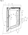
FIG. 1 is a cross-sectional view illustrating a refrigerator according to the present invention, -
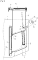
FIG. 2 is a cross-sectional view illustrating the state that the bin is pulled out of the refrigerator inFIG. 1 , -
FIG. 3 is a cross-sectional view illustrating the state that the bin is completely pulled out of the refrigerator inFIG. 1 . - Embodiments will now be described in detail with reference to the accompanying drawings. The idea of the present invention is, however, not limited to the above-mentioned embodiments, and new preferred embodiments included in the scope of the claims can be proposed.
- Referring to
FIG. 1 , acasing 10 is arranged in thebody 1 of the refrigerator. Thecasing 10 forms a sort of storage space 20 in substance. Thecasing 10 contains abin 30 that can be pulled out and pushed in. agrip 31 that users can grip and pull is formed on the front of thebin 30. Thebin 30 is formed in shape of a box that the top is opened. It is possible for this kind of shape of thebin 30 to be changed in various ways in accordance with the shape of the storage space formed bycasing 10. - A
cover 40 is arranged on the top of thebin 30. Thecover 40 is arranged to cover the opened top of thebin 30. Apath 41 is formed in thecover 40. Cool air flows through thepath 41 to cool the foods stored in thebin 30. -
Guide devices 100 are arranged in the storage space 20. Here, it is possible for theguide devices 100 to be arranged at the both sides of the storage space 20. Theguide device 100 includes aguide rail 110 and aguide rib 120. - The
guide rail 110 is arranged at the both sides of the storage space 20. The guide rail is arranged as drawing long along the pulling direction of thebin 30. Here, it is possible for theguide rail 100 to be formed in a single structure with the storage space 20, or to be coupled with the both sides of the storage space 20 by separate coupling members. - It is possible for the
guide rail 100 to be composed of anupper guide rail 111 and alower guide rail 112. Here, it is possible for the upper and lower guide rails to be arranged as adjacent to each other in the up and down positions with a predetermined interval. Further, it is possible that a reinforcingreeve 120 are formed the upper andlower guide rails 112 to reinforce the strength. - A moving
guide rib 120 is coupled with theguide rail 110. Theguide rib 120 is formed at the external of thebin 30. It is possible for theguide rib 120 to be formed as drawing long along the pulling direction of thebin 30. - It is possible for the
guide rib 120 to be formed as unified with thebin 30 or to be coupled at the external of the bin by separate coupling members. Here, theguide rib 120 is arranged only at a side of thebin 30 when theguide rail 110 is arranged only at a side of the storage space 20. Further, theguide rib 120 is arranged at both sides of thebin 30 when theguide rail 110 is arranged at both sides of the storage space 20. Furthermore, though it is not illustrated, it is possible that aseparate roller 130 is arranged at each of the upper andlower guide rail 112. - The
guide device 100 is arranged as inclined against the pulling direction of thebin 30. Theguide rail 110 and theguide rib 120 are arranged as being inclined as the front of thebody 1 is relatively higher than the rear of thebody 1. Therefore, it is possible to minimize the drooping of the bin when thebin 30 is pulled out of the storage space 20. Furthermore, it is convenient to push thebin 30 into the storage space 20, since thebin 30 is not drooping down. - It is possible that a
roller 130 is arranged at the both sides of the storage space 20. Here, it is possible for theroller 130 to be arranged at the front of theguide rail 110 to support the bottom of theguide rib 120 when thebin 30 is pulled out. The roller is installed to be rotated with therotating shaft 131 as centering. It is possible for therotating shaft 131 to be arranged at the position almost same to the front end of thelower guide rail 112. - A
stopper 140 is arranged at the storage space 20 to support the rear of thebin 30 at the state that the bin is pulled out. Thestopper 140 is arranged to support the rear top of thebin 30 at the state that the bin is pulled out. Further, it is also possible for thestopper 140 to be arranged to support both rear sides of thebin 30 at the state that thebin 30 is pulled out. Thestopper 140 as above prevents the drooping down of thebin 30 at the state that thebin 30 is pulled out. - It is possible that an
protrusion 141 is formed at the front of thestopper 140. Theprotrusion 141 restricts the top of thebin 30 when thebin 30 pulled out of the storage space 20 is about to be drooping down. Therefore, theprotrusion 141 prevents the drooping of thebin 30 even when thebin 30 is pulled out, and also prevents the separation of theguide rib 120 from theguide rail 110. - An inclined part 142 is formed at the front of the
protrusion 141. The inclined part 142 let thebin 30 be smoothly moved when pushing thebin 30 into the storage space 20 after washing the bin. - Further, a supporting
unit 143 is formed at the rear of thestopper 140. The supportingunit 143 supports the rear top of thebin 30 at the state that thebin 30 is pulled out. - Furthermore, it is possible for the
roller 130 to be arranged before the stopper at the front. Here, thestopper 140 restricts the top of thebin 30 after the rotating shaft of the bin at the rear, when thebin 30 is about to be rotated with theroller 130 as the rotating center at the state that thebin 30 is pulled out. Therefore, it is prevented that the bin is drooping down as rotated. - Further, it is possible that a
restriction portion 121 is formed at theguide rail 110 to prevent the bottom of thebin 30 going backward at the state that thebin 30 is pulled out. It is possible for therestriction portion 121 to be protruded at the lower side of theguide rail 110. Therefore, therestriction portion 121 is arranged at the front of theroller 130 when the bin is completely pulled out. It is possible for therestriction portion 121 to be rounded so as to cross along theroller 130 when thebin 30 is pulled out. Afirst guide unit 125 is formed at the front end of therestriction portion 121. Thefirst guide unit 125 leads theroller 130 to cross along therestriction portion 121 when thebin 30 is pulled out of the storage space 20. - Further, a
second guide unit 126 is formed at the rear of therestriction portion 121. Thesecond guide unit 126 leads theroller 130 to cross along therestriction portion 121 when thebin 30 is pushed into the storage space 20. Furthermore, theroller 130 prevents that thesecond guiding unit 126 is pushed back, since theroller 130 is engaged with thesecond guiding unit 126 when thebin 30 is pulled out of the storage space 20. Therefore, the bin stays as inclined upwardly. - It is advisable for the first and the
second guide units 126 to be formed as symmetrized against each other. Therefore, it is minimized that the roller is interfered byrestriction portion 121 at the process that thebin 30 is pulled out. - It is possible for the bottom of the
bin 30 to be adjacent to the bottom of the storage space 20 at the state that thebin 30 is arranged in the inside of the storage space 20. - Reference will now be made in detail as for the operation of the preferred embodiment of a refrigerator according to the present invention.
- The process that the
bin 30 is pulled out is illustrated inFIGS. 3 and 4. - Referring to
FIG. 3 , thebin 30 is pulled out toward the front of the storage space 20 when a user pulls the grip of thebin 30. Theguide rib 120 moves along theguide rail 110 as sliding with thebin 30. Theroller 130 supporting theguide rib 120 is rotated as theguide rib 120 is moved. Here, thebin 30 is pulled out as a little inclined upwardly, since theguide rail 110 and theguide rib 120 are arranged to be inclined upwardly. - Referring to
FIG 3 , theguide rib 120 completely separated from theguide rail 110 when thebin 30 keeps pulled out of the storage space 20. Here, theroller 130 is rotated along thefirst guide unit 125 of therestriction portion 121. Therestriction portion 121 is engaged with theroller 130 when thebin 30 is pulled out till the roller contacts thesecond guide unit 126 of therestriction portion 121. At the same time, the rear top of thebin 30 is engaged with theprotrusion 141 of thestopper 140. Here, a rotating torque with the roller as rotating center by the weight of bin and the weight of foods contained is engaged with thebin 30. However, thebin 30 is not rotated with the roller as centering, but is maintained as inclined upwardly, since therestriction portion 121 arranged at the lower side of thebin 30 is at the state engaged withroller 130 and the rear top of thebin 30 is engaged with theprotrusion 141 of thestopper 140. Therefore, it is prevented that thebin 30 is drooping down when it is pulled out of the storage space 20. Further, the inconvenience suiting theguide rib 120 on theguide rail 110 when users push thebin 30 back into the storage space 20 is overcome, since it is prevented that thebin 30 is completely pulled out and separated from theguide device 100. - The industrial applicability of the refrigerator according to the present invention configured as above is very high as the bin of the refrigerator is effectively pulled out.
Claims (5)
- A refrigerator comprising:a body (1) having a storage space (20);a bin (30) arranged in the storage space to be pulled out;a guide rail (110) arranged at the storage space;a guide rib (120) arranged at a side of the bin, and coupled with the guide rail so as to be capable of moving;a roller (130) arranged at the storage space;a stopper (140) preventing the top of the bin from being pulled toward the front at a state that the bin is pulled out; anda restriction portion (121) formed at the guide rib and preventing a lower part of the bin from returning backwards in order to prevent the drooping of the bin (30) when the bin is pulled out,characterized in that:the guide rail (110) and the guide rib (120) are inclined upwardly against the direction that the bin is pulled out; andthe restriction portion (121) comprises a first guide unit (125) formed at a front end of the restriction portion and a second guide unit (126) formed at a rear end of the restriction portion, such that as the bin (30) is pulled out of the storage space (2), the roller (130) is rotated along the first guide unit (125), and at the state that the bin is pulled out, the roller (130) contacts the second guide unit (126) and the stopper (140) supports a rear top of the bin (30).
- The refrigerator according to claim 1, wherein the roller (130) is arranged before the stopper (140) at the front.
- The refrigerator according to claim 1, wherein the stopper (140) is arranged at the upper side of the bin.
- The refrigerator according to claim 1, wherein a protrusion (141) is formed at the stopper (140) so as to restrict the top of the bin at the state that the bin is pulled out.
- The refrigerator according to claim 1, wherein the restriction portion (121) protrudes from the lower side of the guide rib (120).
Applications Claiming Priority (2)
| Application Number | Priority Date | Filing Date | Title |
|---|---|---|---|
| KR1020060034219A KR101233200B1 (en) | 2006-04-14 | 2006-04-14 | A drawing/accepting structure of storage receptacle for refrigerator |
| PCT/KR2007/001804 WO2007119976A1 (en) | 2006-04-14 | 2007-04-13 | Refrigerator |
Publications (3)
| Publication Number | Publication Date |
|---|---|
| EP2010843A1 EP2010843A1 (en) | 2009-01-07 |
| EP2010843A4 EP2010843A4 (en) | 2017-04-05 |
| EP2010843B1 true EP2010843B1 (en) | 2018-12-19 |
Family
ID=38609703
Family Applications (1)
| Application Number | Title | Priority Date | Filing Date |
|---|---|---|---|
| EP07745967.5A Active EP2010843B1 (en) | 2006-04-14 | 2007-04-13 | Refrigerator |
Country Status (7)
| Country | Link |
|---|---|
| US (2) | US8226182B2 (en) |
| EP (1) | EP2010843B1 (en) |
| KR (1) | KR101233200B1 (en) |
| CN (1) | CN101421573B (en) |
| AU (1) | AU2007239194B2 (en) |
| MX (1) | MX2008013247A (en) |
| WO (1) | WO2007119976A1 (en) |
Families Citing this family (23)
| Publication number | Priority date | Publication date | Assignee | Title |
|---|---|---|---|---|
| KR101233200B1 (en) * | 2006-04-14 | 2013-02-15 | 엘지전자 주식회사 | A drawing/accepting structure of storage receptacle for refrigerator |
| DE102009029142A1 (en) * | 2009-09-02 | 2011-03-03 | BSH Bosch und Siemens Hausgeräte GmbH | Refrigeration unit with pull-out shell |
| DE102010002416A1 (en) * | 2010-02-26 | 2011-09-01 | BSH Bosch und Siemens Hausgeräte GmbH | Refrigerating appliance with removable container |
| DE102010039644A1 (en) * | 2010-08-23 | 2012-02-23 | BSH Bosch und Siemens Hausgeräte GmbH | Refrigerating appliance with an extendable refrigerated goods container |
| KR101880098B1 (en) * | 2011-10-13 | 2018-07-23 | 삼성전자주식회사 | Refrigerator |
| EP2629034A1 (en) * | 2012-02-17 | 2013-08-21 | Indesit Company S.p.A. | Refrigerating apparatus for foodstuff products |
| ITRN20120010A1 (en) * | 2012-02-17 | 2013-08-18 | Indesit Co Spa | FOOD REFRIGERATION APPARATUS. |
| CN103795877A (en) * | 2012-10-29 | 2014-05-14 | 殷程 | Intelligent voice |
| CN103112401B (en) * | 2012-12-31 | 2016-02-03 | 佛吉亚内饰系统有限公司 | Hutch equipment |
| US9039110B2 (en) | 2013-03-15 | 2015-05-26 | Whirlpool Corporation | Under mount roller for crisper system |
| KR102028022B1 (en) * | 2013-04-05 | 2019-10-04 | 삼성전자주식회사 | Refrigerator |
| US9194622B2 (en) * | 2013-08-21 | 2015-11-24 | BSH Hausgeräte GmbH | Cooling device having a movable container |
| AU2014330095B2 (en) * | 2013-10-03 | 2017-02-23 | Arcelik Anonim Sirketi | A refrigerator comprising a crisper |
| DE102014219664A1 (en) * | 2014-09-29 | 2016-03-31 | BSH Hausgeräte GmbH | Refrigerating appliance with pull-out box |
| EP3032201B1 (en) * | 2014-12-09 | 2020-02-05 | Liebherr-Hausgeräte Ochsenhausen GmbH | Refrigeration and/or freezer device |
| WO2017057995A1 (en) | 2015-10-02 | 2017-04-06 | 엘지전자 주식회사 | Refrigerator |
| KR102373219B1 (en) | 2015-12-10 | 2022-03-17 | 삼성전자주식회사 | Refrigerator |
| CN108204708B (en) * | 2018-03-02 | 2020-05-26 | 青岛海尔股份有限公司 | Refrigerator and drawer assembly thereof |
| KR102550259B1 (en) * | 2018-08-29 | 2023-07-03 | 엘지전자 주식회사 | Refrigerator |
| US20200224959A1 (en) * | 2019-01-11 | 2020-07-16 | Haier Us Appliance Solutions, Inc. | Soft close drawer assembly for a refrigerator appliance |
| KR102629953B1 (en) * | 2019-03-21 | 2024-01-30 | 삼성전자주식회사 | Refrigrator |
| US11519664B2 (en) | 2020-07-16 | 2022-12-06 | Haler US Appliance Solutions, Inc. | Retractable soft-close shelf system |
| DE102020210280A1 (en) * | 2020-08-13 | 2022-02-17 | BSH Hausgeräte GmbH | Food receiving tray with guide rail tapered towards the rear, as well as guide device and household refrigeration appliance |
Family Cites Families (22)
| Publication number | Priority date | Publication date | Assignee | Title |
|---|---|---|---|---|
| US843194A (en) * | 1906-11-19 | 1907-02-05 | Moses W Coolbaugh | Bin. |
| US1716242A (en) * | 1928-01-10 | 1929-06-04 | Ritsche Theodore | Household bin |
| US1861123A (en) * | 1930-08-27 | 1932-05-31 | Kuckel Herbert | Refrigerator construction |
| US1975327A (en) * | 1933-12-20 | 1934-10-02 | Ralph E Adamson | Refrigerator shelf |
| US2254832A (en) * | 1940-02-23 | 1941-09-02 | Wilmer H Weight | Bookholder for cabinets |
| US2573272A (en) * | 1947-07-21 | 1951-10-30 | Gen Motors Corp | Storage drawer for refrigerating apparatus |
| US2755158A (en) | 1953-11-25 | 1956-07-17 | Gen Electric | Support means for a meat container |
| US3106072A (en) * | 1961-10-03 | 1963-10-08 | Muffly Glenn | Refrigerator-freezer |
| US3722975A (en) * | 1972-01-03 | 1973-03-27 | Rubbermaid Inc | Tilt-open drawer construction |
| US3846001A (en) * | 1973-06-21 | 1974-11-05 | Gutner K | Plastic guide for drawer |
| KR0109836Y1 (en) * | 1994-02-15 | 1995-09-18 | Samsung Electronics Co Ltd | Refrigerator |
| KR100206914B1 (en) | 1996-06-25 | 1999-07-01 | 구본준 | Multi-preset impedance matching apparatus |
| US5820239A (en) * | 1997-06-04 | 1998-10-13 | Maytag Corporation | Storage bin supporting system |
| CN1079531C (en) | 1997-06-11 | 2002-02-20 | 海尔集团公司 | Drawer of under located freezing chamber of electric refrigerator |
| KR100260914B1 (en) * | 1998-03-11 | 2000-07-01 | 윤종용 | Apparatus for withdrawing of vegetables box of refrigerator |
| IL126297A (en) * | 1998-09-18 | 2001-03-19 | Shilav | Safety device for drawers |
| US6193340B1 (en) * | 1999-08-03 | 2001-02-27 | Geographics, Inc. | Snap-together file storage system |
| US20050162054A1 (en) * | 2004-01-26 | 2005-07-28 | Royal Alliance Inc. | Cabinet with shelf supported plastic drawer |
| WO2005083339A1 (en) * | 2004-02-27 | 2005-09-09 | Matsushita Electric Industrial Co., Ltd. | Refrigerator |
| KR200406024Y1 (en) * | 2005-11-03 | 2006-01-11 | 설승원 | Refrigerator |
| KR101233200B1 (en) * | 2006-04-14 | 2013-02-15 | 엘지전자 주식회사 | A drawing/accepting structure of storage receptacle for refrigerator |
| KR101313552B1 (en) * | 2007-02-26 | 2013-10-01 | 삼성전자주식회사 | Refrigerator |
-
2006
- 2006-04-14 KR KR1020060034219A patent/KR101233200B1/en active IP Right Grant
-
2007
- 2007-04-13 AU AU2007239194A patent/AU2007239194B2/en active Active
- 2007-04-13 CN CN2007800134076A patent/CN101421573B/en active Active
- 2007-04-13 US US12/296,823 patent/US8226182B2/en active Active
- 2007-04-13 EP EP07745967.5A patent/EP2010843B1/en active Active
- 2007-04-13 MX MX2008013247A patent/MX2008013247A/en active IP Right Grant
- 2007-04-13 WO PCT/KR2007/001804 patent/WO2007119976A1/en active Application Filing
-
2012
- 2012-06-25 US US13/532,196 patent/US8814285B2/en active Active
Non-Patent Citations (1)
| Title |
|---|
| None * |
Also Published As
| Publication number | Publication date |
|---|---|
| EP2010843A1 (en) | 2009-01-07 |
| US20090309472A1 (en) | 2009-12-17 |
| US8814285B2 (en) | 2014-08-26 |
| MX2008013247A (en) | 2008-10-21 |
| CN101421573B (en) | 2010-06-09 |
| EP2010843A4 (en) | 2017-04-05 |
| AU2007239194B2 (en) | 2010-02-11 |
| CN101421573A (en) | 2009-04-29 |
| WO2007119976A1 (en) | 2007-10-25 |
| KR101233200B1 (en) | 2013-02-15 |
| AU2007239194A1 (en) | 2007-10-25 |
| US8226182B2 (en) | 2012-07-24 |
| KR20070102282A (en) | 2007-10-18 |
| US20120262046A1 (en) | 2012-10-18 |
Similar Documents
| Publication | Publication Date | Title |
|---|---|---|
| EP2010843B1 (en) | Refrigerator | |
| US10935306B2 (en) | Refrigerator | |
| KR102595327B1 (en) | A refrigerator | |
| JP4824371B2 (en) | Refrigerator double drawer | |
| EP2792978B1 (en) | Food container | |
| EP2572149B1 (en) | Refrigerator | |
| EP2532996A1 (en) | Door basket and refrigerator including same | |
| KR102421854B1 (en) | refrigerator | |
| KR101627935B1 (en) | Refrigerator | |
| KR20200025512A (en) | Refrigerator | |
| EP3152502B1 (en) | Refrigerator | |
| KR20140109035A (en) | Refrigerator | |
| KR20080095355A (en) | A drawing out/in structure of container box for refrigerator | |
| KR20140074520A (en) | A refrigerator | |
| KR20100032178A (en) | A shelf of refrigerator and refrigerator including the same | |
| KR100785117B1 (en) | The auto-opening vessel | |
| KR101350056B1 (en) | Refrigerator | |
| KR102421453B1 (en) | A refrigerator | |
| KR200393556Y1 (en) | Structure for preventing fall off of drawer for Kimchi refrigerator | |
| KR20080066452A (en) | Open and close structure of inner door for refrigerator | |
| KR20060032686A (en) | A withdrawal shelf for refrigerator | |
| CN113074490B (en) | A kind of refrigerator | |
| KR200340653Y1 (en) | A home bar of side by side type refrigerator | |
| KR101271893B1 (en) | A Drawing home-bar for refrigerator | |
| KR20110009347A (en) | A refrigerator |
Legal Events
| Date | Code | Title | Description |
|---|---|---|---|
| PUAI | Public reference made under article 153(3) epc to a published international application that has entered the european phase |
Free format text: ORIGINAL CODE: 0009012 |
|
| 17P | Request for examination filed |
Effective date: 20081105 |
|
| AK | Designated contracting states |
Kind code of ref document: A1 Designated state(s): AT BE BG CH CY CZ DE DK EE ES FI FR GB GR HU IE IS IT LI LT LU LV MC MT NL PL PT RO SE SI SK TR |
|
| AX | Request for extension of the european patent |
Extension state: AL BA HR MK RS |
|
| DAX | Request for extension of the european patent (deleted) | ||
| RBV | Designated contracting states (corrected) |
Designated state(s): DE GB IT |
|
| RIC1 | Information provided on ipc code assigned before grant |
Ipc: F25D 25/02 20060101ALI20161122BHEP Ipc: F25D 25/00 20060101AFI20161122BHEP |
|
| RA4 | Supplementary search report drawn up and despatched (corrected) |
Effective date: 20170308 |
|
| RIC1 | Information provided on ipc code assigned before grant |
Ipc: F25D 25/00 20060101AFI20170302BHEP Ipc: F25D 25/02 20060101ALI20170302BHEP |
|
| GRAP | Despatch of communication of intention to grant a patent |
Free format text: ORIGINAL CODE: EPIDOSNIGR1 |
|
| INTG | Intention to grant announced |
Effective date: 20180709 |
|
| GRAS | Grant fee paid |
Free format text: ORIGINAL CODE: EPIDOSNIGR3 |
|
| GRAA | (expected) grant |
Free format text: ORIGINAL CODE: 0009210 |
|
| AK | Designated contracting states |
Kind code of ref document: B1 Designated state(s): DE GB IT |
|
| REG | Reference to a national code |
Ref country code: GB Ref legal event code: FG4D |
|
| REG | Reference to a national code |
Ref country code: DE Ref legal event code: R096 Ref document number: 602007057165 Country of ref document: DE |
|
| PG25 | Lapsed in a contracting state [announced via postgrant information from national office to epo] |
Ref country code: IT Free format text: LAPSE BECAUSE OF FAILURE TO SUBMIT A TRANSLATION OF THE DESCRIPTION OR TO PAY THE FEE WITHIN THE PRESCRIBED TIME-LIMIT Effective date: 20181219 |
|
| REG | Reference to a national code |
Ref country code: DE Ref legal event code: R097 Ref document number: 602007057165 Country of ref document: DE |
|
| PLBE | No opposition filed within time limit |
Free format text: ORIGINAL CODE: 0009261 |
|
| STAA | Information on the status of an ep patent application or granted ep patent |
Free format text: STATUS: NO OPPOSITION FILED WITHIN TIME LIMIT |
|
| 26N | No opposition filed |
Effective date: 20190920 |
|
| GBPC | Gb: european patent ceased through non-payment of renewal fee |
Effective date: 20190413 |
|
| PG25 | Lapsed in a contracting state [announced via postgrant information from national office to epo] |
Ref country code: GB Free format text: LAPSE BECAUSE OF NON-PAYMENT OF DUE FEES Effective date: 20190413 |
|
| PGFP | Annual fee paid to national office [announced via postgrant information from national office to epo] |
Ref country code: DE Payment date: 20230306 Year of fee payment: 17 |