EP2010766B1 - Beheizte harnstoffleitung für abgasnachbehandlungsanlagen von brennkraftmaschinen - Google Patents
Beheizte harnstoffleitung für abgasnachbehandlungsanlagen von brennkraftmaschinen Download PDFInfo
- Publication number
- EP2010766B1 EP2010766B1 EP07726519A EP07726519A EP2010766B1 EP 2010766 B1 EP2010766 B1 EP 2010766B1 EP 07726519 A EP07726519 A EP 07726519A EP 07726519 A EP07726519 A EP 07726519A EP 2010766 B1 EP2010766 B1 EP 2010766B1
- Authority
- EP
- European Patent Office
- Prior art keywords
- hose
- conduit
- heated
- internal combustion
- combustion engines
- Prior art date
- Legal status (The legal status is an assumption and is not a legal conclusion. Google has not performed a legal analysis and makes no representation as to the accuracy of the status listed.)
- Active
Links
Images

Classifications
-
- F—MECHANICAL ENGINEERING; LIGHTING; HEATING; WEAPONS; BLASTING
- F16—ENGINEERING ELEMENTS AND UNITS; GENERAL MEASURES FOR PRODUCING AND MAINTAINING EFFECTIVE FUNCTIONING OF MACHINES OR INSTALLATIONS; THERMAL INSULATION IN GENERAL
- F16L—PIPES; JOINTS OR FITTINGS FOR PIPES; SUPPORTS FOR PIPES, CABLES OR PROTECTIVE TUBING; MEANS FOR THERMAL INSULATION IN GENERAL
- F16L59/00—Thermal insulation in general
- F16L59/14—Arrangements for the insulation of pipes or pipe systems
- F16L59/153—Arrangements for the insulation of pipes or pipe systems for flexible pipes
-
- F—MECHANICAL ENGINEERING; LIGHTING; HEATING; WEAPONS; BLASTING
- F16—ENGINEERING ELEMENTS AND UNITS; GENERAL MEASURES FOR PRODUCING AND MAINTAINING EFFECTIVE FUNCTIONING OF MACHINES OR INSTALLATIONS; THERMAL INSULATION IN GENERAL
- F16L—PIPES; JOINTS OR FITTINGS FOR PIPES; SUPPORTS FOR PIPES, CABLES OR PROTECTIVE TUBING; MEANS FOR THERMAL INSULATION IN GENERAL
- F16L53/00—Heating of pipes or pipe systems; Cooling of pipes or pipe systems
- F16L53/30—Heating of pipes or pipe systems
- F16L53/32—Heating of pipes or pipe systems using hot fluids
-
- F—MECHANICAL ENGINEERING; LIGHTING; HEATING; WEAPONS; BLASTING
- F01—MACHINES OR ENGINES IN GENERAL; ENGINE PLANTS IN GENERAL; STEAM ENGINES
- F01N—GAS-FLOW SILENCERS OR EXHAUST APPARATUS FOR MACHINES OR ENGINES IN GENERAL; GAS-FLOW SILENCERS OR EXHAUST APPARATUS FOR INTERNAL-COMBUSTION ENGINES
- F01N2610/00—Adding substances to exhaust gases
- F01N2610/02—Adding substances to exhaust gases the substance being ammonia or urea
-
- F—MECHANICAL ENGINEERING; LIGHTING; HEATING; WEAPONS; BLASTING
- F01—MACHINES OR ENGINES IN GENERAL; ENGINE PLANTS IN GENERAL; STEAM ENGINES
- F01N—GAS-FLOW SILENCERS OR EXHAUST APPARATUS FOR MACHINES OR ENGINES IN GENERAL; GAS-FLOW SILENCERS OR EXHAUST APPARATUS FOR INTERNAL-COMBUSTION ENGINES
- F01N2610/00—Adding substances to exhaust gases
- F01N2610/10—Adding substances to exhaust gases the substance being heated, e.g. by heating tank or supply line of the added substance
-
- F—MECHANICAL ENGINEERING; LIGHTING; HEATING; WEAPONS; BLASTING
- F01—MACHINES OR ENGINES IN GENERAL; ENGINE PLANTS IN GENERAL; STEAM ENGINES
- F01N—GAS-FLOW SILENCERS OR EXHAUST APPARATUS FOR MACHINES OR ENGINES IN GENERAL; GAS-FLOW SILENCERS OR EXHAUST APPARATUS FOR INTERNAL-COMBUSTION ENGINES
- F01N2610/00—Adding substances to exhaust gases
- F01N2610/14—Arrangements for the supply of substances, e.g. conduits
-
- F—MECHANICAL ENGINEERING; LIGHTING; HEATING; WEAPONS; BLASTING
- F01—MACHINES OR ENGINES IN GENERAL; ENGINE PLANTS IN GENERAL; STEAM ENGINES
- F01N—GAS-FLOW SILENCERS OR EXHAUST APPARATUS FOR MACHINES OR ENGINES IN GENERAL; GAS-FLOW SILENCERS OR EXHAUST APPARATUS FOR INTERNAL-COMBUSTION ENGINES
- F01N2610/00—Adding substances to exhaust gases
- F01N2610/14—Arrangements for the supply of substances, e.g. conduits
- F01N2610/1473—Overflow or return means for the substances, e.g. conduits or valves for the return path
-
- Y—GENERAL TAGGING OF NEW TECHNOLOGICAL DEVELOPMENTS; GENERAL TAGGING OF CROSS-SECTIONAL TECHNOLOGIES SPANNING OVER SEVERAL SECTIONS OF THE IPC; TECHNICAL SUBJECTS COVERED BY FORMER USPC CROSS-REFERENCE ART COLLECTIONS [XRACs] AND DIGESTS
- Y02—TECHNOLOGIES OR APPLICATIONS FOR MITIGATION OR ADAPTATION AGAINST CLIMATE CHANGE
- Y02T—CLIMATE CHANGE MITIGATION TECHNOLOGIES RELATED TO TRANSPORTATION
- Y02T10/00—Road transport of goods or passengers
- Y02T10/10—Internal combustion engine [ICE] based vehicles
- Y02T10/12—Improving ICE efficiencies
Definitions
- the invention relates to a heated urea line for an exhaust aftertreatment system of internal combustion engines.
- aqueous urea solution is used, which is carried in a separate reservoir.
- the hose lines between the reservoir and the exhaust pipe must be heatable, since the risk of freezing the aqueous urea solution from -11 ° C consists. It is known to use electrically heatable hoses.
- the invention has for its object to provide a heated urea line, which acts sufficiently and safely without the use of electrical energy.
- the object is achieved in that a hose leading the aqueous urea solution runs parallel to a hose leading to heating water and that both hoses are closely embraced by a shrinking tube when heated.
- the hose leading the urea solution is laid in parallel with a hose leading to heating water, preferably made of thermally conductive Elastomer exists.
- the shrink tube is a tissue shrink tube.
- the fabric may be, for example, polyester coated with a polyolefin.
- the fabric shrink tubing causes a close contact between two parallel tubes, which ensures a good heat transfer.
- the fabric shrink tube is sewn together paraxial and has sufficient structural elongation. This leads to a flexibility that is needed for good laying properties of the hose package within the engine compartment.
- the tissue shrinks, so that the two hoses forming the hose package run constantly adjacent to each other, whereby the line contact is held securely.
- the hose pair combined by the shrink tubing is surrounded by an insulating foam tube.
- the heat emitted by the heating water is thus purposefully fed to the hose leading the urea solution.
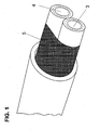
- aqueous urea solution leading hose 3 is arranged in parallel next to a heating water leading hose 4.
- Both hoses 3 and 4 are comprised of a fabric shrink tubing 5 which exhibits shrinkage properties upon heating.
- the two media-carrying tubes 3 and 4 enclosed by the tissue shrink tubing 5 are pressed against each other under line contact. This creates a kind of heat exchanger effect.
- the heat present in the heating water of the one hose 4 is delivered to the hose 3 carrying the urea solution. The heat transfer is sufficient that the urea solution does not freeze.
- the tube pair 3 and 4 enclosed by the tissue shrink tubing 5 run in an insulating foam tube 7.
Landscapes
- Engineering & Computer Science (AREA)
- General Engineering & Computer Science (AREA)
- Mechanical Engineering (AREA)
- Rigid Pipes And Flexible Pipes (AREA)
- Exhaust Gas After Treatment (AREA)
- Exhaust Gas Treatment By Means Of Catalyst (AREA)
- Thermal Insulation (AREA)
- Pipe Accessories (AREA)
Description
- Die Erfindung betrifft eine beheizte Harnstoffleitung für eine Abgasnachbehandlungsanlage von Brennkraftmaschinen.
- Zur Verminderung von Stickoxidemissionen einer Brennkraftmaschine ist es bekannt, mit Hilfe der Selektiv-Catalytic-Reduktion-Technologie (SCR) Stickoxid in Luftstickstoff und Wasserdampf umzuwandeln. Als Reduktionsmittel wird wässrige Harnstofflösung verwandt, die in einem separaten Vorratsbehälter mitgeführt wird.
- Die Schlauchleitungen zwischen dem Vorratsbehälter und der Abgasleitung müssen beheizbar sein, da die Gefahr des Einfrierens der wässrigen Harnstofflösung ab -11°C besteht. Es ist bekannt, elektrisch beheizbare Schläuche einzusetzen.
- Der Erfindung liegt die Aufgabe zugrunde, eine beheizte Harnstoffleitung zu schaffen, die ohne die Verwendung elektrischer Energie ausreichend und sicher wirkt.
- Dokument
US6845611 B2 offenbart eine beheizte Harnstoffleitung wobei eine die Harnstofflösung führende Schlauchleitung parallel mit einem Brennstoffführende Schlauch verläuft. - Die Aufgabe wird erfindungsgemäß dadurch gelöst, dass eine die wässrige Harnstofflösung führende Schlauchleitung parallel mit einem Heizwasser führenden Schlauch verläuft und dass beide Schläuche von einem bei Erwärmung schrumpfenden Schlauch eng umfasst sind.
- Durch die Erfindung wird der die Harnstofflösung führende Schlauch parallel mit einem Heizwasser führenden Schlauch verlegt, der vorzugsweise aus wärmeleitfähigem Elastomer besteht. Der bei Erwärmung schrumpfende Schlauch (Schrumpfschlauch) presst die beiden Schläuche zusammen, wodurch ein guter Wärmeübergang erreicht wird.
- In vorteilhafter Ausgestaltung der Erfindung ist der Schrumpfschlauch ein Gewebeschrumpfschlauch. Das Gewebe kann beispielsweise aus Polyester sein, dass mit einem Polyolefin beschichtet ist.
- Der Gewebeschrumpfschlauch bewirkt eine enge Berührung zwischen beiden parallel verlaufenden Schläuchen, was für einen guten Wärmeübergang sorgt. Der Gewebeschrumpfschlauch ist achsparallel zusammengenäht und weist eine ausreichende konstruktive Dehnung auf. Dieses führt zu einer Flexibilität, die für gute Verlegeeigenschaften des Schlauchpaketes innerhalb des Motorraumes benötigt werden.
- Durch Erwärmen schrumpft das Gewebe, so dass die beiden das Schlauchpaket bildenden Schläuche konstant aneinander liegend verlaufen, wobei die Linienberührung sicher gehalten wird.
- In weiterer vorteilhafter Ausgestaltung der Erfindung ist das durch den Schrumpfschlauch zusammengefasste Schlauchpaar von einem isolierenden Schaumstoffschlauch umgeben. Die vom Heizwasser abgegebene Wärme wird so zielgerichtet dem die Harnstofflösung führenden Schlauch zugeführt.
- Anhand der Zeichnung wird ein Ausführungsbeispiel der Erfindung näher erläutert.
- Es zeigt
- Fig. 1
- in perspektivischer Darstellung das von einem Gewebeschrumpfschlauch zusammengefasste Schlauchpaar;
- Fig. 2
- einen Querschnitt der in
Fig. 1 gezeigten Anordnung. - Ein wässrige Harnstofflösung führender Schlauch 3 ist parallel neben einem Heizwasser führenden Schlauch 4 angeordnet. Beide Schläuche 3 und 4 sind von einem Gewebeschrumpfschlauch 5 umfasst, der bei Erwärmen Schrumpfeigenschaften aufweist. Die beiden von dem Gewebeschrumpfschlauch 5 umfassten medienführenden Schläuche 3 und 4 werden unter Linienberührung aneinander gepresst. Dadurch entsteht eine Art Wärmetauschereffekt. Die in dem Heizwasser des einen Schlauches 4 vorhandene Wärme wird an den die Harnstofflösung führenden Schlauch 3 abgegeben. Der Wärmeübergang reicht aus, dass die Harnstofflösung nicht einfriert.
- Das von dem Gewebeschrumpfschlauch 5 umfasste Schlauchpaar 3 und 4 verläuft in einem isolierenden Schaumstoffschlauch 7.
Claims (4)
- Beheizte Harnstoffleitung für Abgasnachbehandlungsanlagen von Brennkraftmaschinen,
dadurch gekennzeichnet,
dass eine die wässrige Harnstofflösung führende Schlauchleitung (3) parallel mit einem Heizwasser führenden Schlauch (4) verläuft und dass beide Schläuche (3 und 4) von einem bei Erwärmung schrumpfenden Schlauch (5) umfasst sind. - Beheizte Harnstoffleitung nach Anspruch 1, dadurch gekennzeichnet,
dass der Schrumpfschlauch (5) aus einem schrumpffähigen, flexiblen Gewebe besteht. - Beheizte Harnstoffleitung nach Anspruch 2, dadurch gekennzeichnet, dass das Gewebe ein mit Polyolefin beschichtetes Gewebe ist.
- Harnstoffleitung nach einem der Ansprüche 1 bis 3, dadurch gekennzeichnet, dass das durch den Schrumpfschlauch (5) zusammengefasste Schlauchpaar (3 und 4) von einem isolierenden Schaumstoffschlauch (7) umgeben ist.
Applications Claiming Priority (2)
| Application Number | Priority Date | Filing Date | Title |
|---|---|---|---|
| DE102006017414A DE102006017414A1 (de) | 2006-04-13 | 2006-04-13 | Beheizte Harnstoffleitung für Abgasnachbehandlungsanlagen von Brennkraftmaschinen |
| PCT/EP2007/051820 WO2007118728A1 (de) | 2006-04-13 | 2007-02-27 | Beheizte harnstoffleitung für abgasnachbehandlungsanlagen von brennkraftmaschinen |
Publications (2)
| Publication Number | Publication Date |
|---|---|
| EP2010766A1 EP2010766A1 (de) | 2009-01-07 |
| EP2010766B1 true EP2010766B1 (de) | 2010-08-18 |
Family
ID=37986788
Family Applications (1)
| Application Number | Title | Priority Date | Filing Date |
|---|---|---|---|
| EP07726519A Active EP2010766B1 (de) | 2006-04-13 | 2007-02-27 | Beheizte harnstoffleitung für abgasnachbehandlungsanlagen von brennkraftmaschinen |
Country Status (5)
| Country | Link |
|---|---|
| US (1) | US20090071132A1 (de) |
| EP (1) | EP2010766B1 (de) |
| AT (1) | ATE478243T1 (de) |
| DE (2) | DE102006017414A1 (de) |
| WO (1) | WO2007118728A1 (de) |
Families Citing this family (12)
| Publication number | Priority date | Publication date | Assignee | Title |
|---|---|---|---|---|
| DE102008057258A1 (de) | 2008-11-13 | 2010-05-20 | Albonair Gmbh | Komponententräger für ein Dosiersystem |
| US9719395B2 (en) | 2011-05-10 | 2017-08-01 | Albonair Gmbh | Component carrier for a dosing system |
| CN103046986B (zh) * | 2012-12-26 | 2016-08-10 | 潍柴动力股份有限公司 | 一种scr系统及其尿素加热装置、尿素加热方法 |
| JP2016070189A (ja) * | 2014-09-30 | 2016-05-09 | ニッタ株式会社 | 断熱配管 |
| FR3053731B1 (fr) * | 2016-07-05 | 2020-05-15 | Renault S.A.S | Systeme de chauffage passif d'un systeme scr |
| GB2554850A (en) * | 2016-07-12 | 2018-04-18 | Ramfoam Ltd | Conduit formation and use |
| DE102017108532A1 (de) * | 2017-04-21 | 2018-10-25 | Norma Germany Gmbh | Leitungsanordnung |
| DE102017125104A1 (de) | 2017-10-26 | 2019-05-02 | Elmeric Gmbh | Beheizbarer flexibler Schlauch mit aufgebrachtem Heizelement |
| DE202017106495U1 (de) | 2017-10-26 | 2017-11-13 | Elmeric Gmbh | Beheizbarer flexibler Schlauch mit aufgebrachtem Heizelement |
| DE102018113632A1 (de) * | 2018-06-07 | 2019-12-12 | Norma Germany Gmbh | Führungskanal und Leitungsanordnung |
| IT202300021264A1 (it) * | 2023-10-12 | 2025-04-12 | Bosch Gmbh Robert | Connettore per alimentare fluido per gas di scarico diesel |
| CN118959772B (zh) * | 2024-10-21 | 2024-12-13 | 永忠工程管理(集团)有限公司 | 一种高寒地区厕所用防堵塞管道 |
Family Cites Families (22)
| Publication number | Priority date | Publication date | Assignee | Title |
|---|---|---|---|---|
| US3151633A (en) * | 1961-03-29 | 1964-10-06 | Owens Corning Fiberglass Corp | Shaped thermal insulation for pipe |
| US3269422A (en) * | 1963-01-09 | 1966-08-30 | Moore & Co Samuel | Composite tubing product and apparatus and method for manufacturing the same |
| BE667728A (de) * | 1964-08-28 | |||
| NL6414630A (de) * | 1964-12-16 | 1966-06-17 | ||
| US3853149A (en) * | 1970-05-14 | 1974-12-10 | Moore & Co Samuel | Composite tubing |
| US3669157A (en) * | 1970-06-01 | 1972-06-13 | Carolina Narrow Fabric Co | Shrinkable tubular fabric |
| US3955601A (en) * | 1972-11-29 | 1976-05-11 | Moore Business Forms, Inc. | Heat insulating jacket for a conduit equipped with self-locking seam |
| US4123837A (en) * | 1976-02-12 | 1978-11-07 | Exxon Research & Engineering Co. | Heat transfer method |
| US4194536A (en) * | 1976-12-09 | 1980-03-25 | Eaton Corporation | Composite tubing product |
| US4461347A (en) * | 1981-01-27 | 1984-07-24 | Interlab, Inc. | Heat exchange assembly for ultra-pure water |
| US4399319A (en) * | 1981-11-18 | 1983-08-16 | Bio-Energy Systems, Inc. | Thermally insulated composite flexible hose |
| US4631098A (en) * | 1983-01-06 | 1986-12-23 | Raychem Limited | Heat-recoverable article |
| GB8528966D0 (en) * | 1985-11-25 | 1986-01-02 | Raychem Ltd | Wrap-around fabric articles |
| DE3925704A1 (de) * | 1989-08-03 | 1991-02-21 | Wieland Werke Ag | Waermeaustauscher |
| DE4438093C1 (de) * | 1994-10-25 | 1996-03-28 | Continental Ag | Be- und Entlüftungseinrichtung für Teile von Kraftfahrzeugmotoren |
| JP2001240414A (ja) * | 2000-02-28 | 2001-09-04 | Miura Co Ltd | アンモニア生成装置 |
| DE20119514U1 (de) * | 2001-12-03 | 2002-02-28 | PUREM Abgassysteme GmbH & Co. KG, 58706 Menden | Reduktionsmitteldosiereinrichtung |
| US6810916B2 (en) * | 2003-01-24 | 2004-11-02 | Dt Search & Designs, Llc | Heated drain line apparatus |
| JP3751962B2 (ja) * | 2003-09-05 | 2006-03-08 | 日産ディーゼル工業株式会社 | エンジンの排気浄化装置 |
| GB2418478A (en) * | 2004-09-24 | 2006-03-29 | Ti Group Automotive Sys Ltd | A heat exchanger |
| JP4730216B2 (ja) * | 2005-09-26 | 2011-07-20 | 株式会社デンソー | 還元剤改質装置およびこれを用いた排気ガス浄化装置 |
| DE102006017399A1 (de) * | 2006-04-13 | 2007-10-18 | Contitech Techno-Chemie Gmbh | Beheizbares Schlauchleitungssystem für Abgasnachbehandlungsanlagen von Brennkraftmaschinen |
-
2006
- 2006-04-13 DE DE102006017414A patent/DE102006017414A1/de not_active Withdrawn
-
2007
- 2007-02-27 DE DE502007004789T patent/DE502007004789D1/de active Active
- 2007-02-27 EP EP07726519A patent/EP2010766B1/de active Active
- 2007-02-27 AT AT07726519T patent/ATE478243T1/de active
- 2007-02-27 WO PCT/EP2007/051820 patent/WO2007118728A1/de not_active Ceased
-
2008
- 2008-10-09 US US12/285,584 patent/US20090071132A1/en not_active Abandoned
Also Published As
| Publication number | Publication date |
|---|---|
| WO2007118728A1 (de) | 2007-10-25 |
| DE502007004789D1 (de) | 2010-09-30 |
| US20090071132A1 (en) | 2009-03-19 |
| ATE478243T1 (de) | 2010-09-15 |
| EP2010766A1 (de) | 2009-01-07 |
| DE102006017414A1 (de) | 2007-10-18 |
Similar Documents
| Publication | Publication Date | Title |
|---|---|---|
| WO2007118728A1 (de) | Beheizte harnstoffleitung für abgasnachbehandlungsanlagen von brennkraftmaschinen | |
| EP2167860B1 (de) | Anschlussvorrichtung für medienführende, elektrisch beheizbare schläuche | |
| EP2655950B1 (de) | Konfektionierte medienleitung sowie verwendung in einem scr-katalysator-system | |
| US20100175469A1 (en) | Electrically heated fluid tube | |
| US20100209085A1 (en) | Heated fluid conduits, systems and methods | |
| EP1519098A1 (de) | Elektrisch beheizbare Flüssigkeitsleitung | |
| WO2007118772A1 (de) | Beheizbares schlauchleitungssystem für abgasnachbehandlungsanlagen von brennkraftmaschinen | |
| CN109139203A (zh) | 用于排气处理的碰撞式混合器 | |
| EP2462371A1 (de) | Beheizbares schlauchsystem | |
| EP2652382B1 (de) | Beheizbare anschlussvorrichtung für medienführende, elektrisch beheizbare schläuche | |
| WO2009095941A1 (en) | Multilayer hose for conveying an aqueous solution containing urea | |
| EP1770251B1 (de) | Beheizbarer Schlauchleitungsmodul für Abgasnachbehandlungsanlagen von Brennkraftmaschinen | |
| WO2018114330A1 (de) | Leitungsstrang zur temperierten führung eines reduktionsmittels für die abgasnachbehandlung einer brennkraftmaschine | |
| DE102011053053A1 (de) | Schlauchleitung | |
| DE112020002964B4 (de) | Auslasssystem und Schalldämpfer | |
| EP2619495B1 (de) | Leitungsystem für ein scr system in einem kraftfahrzeug | |
| EP3198121A1 (de) | Abgasnachbehandlungssystem für verbrennungsmotoren | |
| US20080041841A1 (en) | Piping with heater and connecting method of the piping | |
| DE102020116485A1 (de) | Abgasanlagenbauteil mit schraubenförmiger heizeinrichtung | |
| EP2662606B1 (de) | Schutzrohr für eine zu temperierende Medienleitung und Leitungsaggregat | |
| DE102019209792A1 (de) | System und Verfahren zur Abgasnachbehandlung | |
| EP3612759A1 (de) | Leitungsanordnung | |
| DE102014112731B4 (de) | Temperierte SCR-Leitung und temperiertes SCR-Leitungsbündel | |
| EP3543580B1 (de) | Beheizte medienleitung | |
| DE202008013048U1 (de) | Mediumkupplung mit elektrischem Anschluss |
Legal Events
| Date | Code | Title | Description |
|---|---|---|---|
| PUAI | Public reference made under article 153(3) epc to a published international application that has entered the european phase |
Free format text: ORIGINAL CODE: 0009012 |
|
| 17P | Request for examination filed |
Effective date: 20081113 |
|
| AK | Designated contracting states |
Kind code of ref document: A1 Designated state(s): AT BE BG CH CY CZ DE DK EE ES FI FR GB GR HU IE IS IT LI LT LU LV MC NL PL PT RO SE SI SK TR |
|
| AX | Request for extension of the european patent |
Extension state: AL BA HR MK RS |
|
| GRAP | Despatch of communication of intention to grant a patent |
Free format text: ORIGINAL CODE: EPIDOSNIGR1 |
|
| GRAS | Grant fee paid |
Free format text: ORIGINAL CODE: EPIDOSNIGR3 |
|
| GRAA | (expected) grant |
Free format text: ORIGINAL CODE: 0009210 |
|
| AK | Designated contracting states |
Kind code of ref document: B1 Designated state(s): AT BE BG CH CY CZ DE DK EE ES FI FR GB GR HU IE IS IT LI LT LU LV MC NL PL PT RO SE SI SK TR |
|
| REG | Reference to a national code |
Ref country code: GB Ref legal event code: FG4D Free format text: NOT ENGLISH |
|
| REG | Reference to a national code |
Ref country code: CH Ref legal event code: EP |
|
| REG | Reference to a national code |
Ref country code: IE Ref legal event code: FG4D Free format text: LANGUAGE OF EP DOCUMENT: GERMAN |
|
| REF | Corresponds to: |
Ref document number: 502007004789 Country of ref document: DE Date of ref document: 20100930 Kind code of ref document: P |
|
| REG | Reference to a national code |
Ref country code: SE Ref legal event code: TRGR |
|
| REG | Reference to a national code |
Ref country code: NL Ref legal event code: VDEP Effective date: 20100818 |
|
| LTIE | Lt: invalidation of european patent or patent extension |
Effective date: 20100818 |
|
| PG25 | Lapsed in a contracting state [announced via postgrant information from national office to epo] |
Ref country code: LT Free format text: LAPSE BECAUSE OF FAILURE TO SUBMIT A TRANSLATION OF THE DESCRIPTION OR TO PAY THE FEE WITHIN THE PRESCRIBED TIME-LIMIT Effective date: 20100818 Ref country code: FI Free format text: LAPSE BECAUSE OF FAILURE TO SUBMIT A TRANSLATION OF THE DESCRIPTION OR TO PAY THE FEE WITHIN THE PRESCRIBED TIME-LIMIT Effective date: 20100818 |
|
| PG25 | Lapsed in a contracting state [announced via postgrant information from national office to epo] |
Ref country code: SI Free format text: LAPSE BECAUSE OF FAILURE TO SUBMIT A TRANSLATION OF THE DESCRIPTION OR TO PAY THE FEE WITHIN THE PRESCRIBED TIME-LIMIT Effective date: 20100818 Ref country code: PT Free format text: LAPSE BECAUSE OF FAILURE TO SUBMIT A TRANSLATION OF THE DESCRIPTION OR TO PAY THE FEE WITHIN THE PRESCRIBED TIME-LIMIT Effective date: 20101220 Ref country code: IS Free format text: LAPSE BECAUSE OF FAILURE TO SUBMIT A TRANSLATION OF THE DESCRIPTION OR TO PAY THE FEE WITHIN THE PRESCRIBED TIME-LIMIT Effective date: 20101218 Ref country code: CY Free format text: LAPSE BECAUSE OF FAILURE TO SUBMIT A TRANSLATION OF THE DESCRIPTION OR TO PAY THE FEE WITHIN THE PRESCRIBED TIME-LIMIT Effective date: 20100818 Ref country code: BG Free format text: LAPSE BECAUSE OF FAILURE TO SUBMIT A TRANSLATION OF THE DESCRIPTION OR TO PAY THE FEE WITHIN THE PRESCRIBED TIME-LIMIT Effective date: 20101118 Ref country code: PL Free format text: LAPSE BECAUSE OF FAILURE TO SUBMIT A TRANSLATION OF THE DESCRIPTION OR TO PAY THE FEE WITHIN THE PRESCRIBED TIME-LIMIT Effective date: 20100818 |
|
| REG | Reference to a national code |
Ref country code: IE Ref legal event code: FD4D |
|
| PG25 | Lapsed in a contracting state [announced via postgrant information from national office to epo] |
Ref country code: NL Free format text: LAPSE BECAUSE OF FAILURE TO SUBMIT A TRANSLATION OF THE DESCRIPTION OR TO PAY THE FEE WITHIN THE PRESCRIBED TIME-LIMIT Effective date: 20100818 Ref country code: LV Free format text: LAPSE BECAUSE OF FAILURE TO SUBMIT A TRANSLATION OF THE DESCRIPTION OR TO PAY THE FEE WITHIN THE PRESCRIBED TIME-LIMIT Effective date: 20100818 Ref country code: GR Free format text: LAPSE BECAUSE OF FAILURE TO SUBMIT A TRANSLATION OF THE DESCRIPTION OR TO PAY THE FEE WITHIN THE PRESCRIBED TIME-LIMIT Effective date: 20101119 |
|
| PG25 | Lapsed in a contracting state [announced via postgrant information from national office to epo] |
Ref country code: IE Free format text: LAPSE BECAUSE OF FAILURE TO SUBMIT A TRANSLATION OF THE DESCRIPTION OR TO PAY THE FEE WITHIN THE PRESCRIBED TIME-LIMIT Effective date: 20100818 Ref country code: DK Free format text: LAPSE BECAUSE OF FAILURE TO SUBMIT A TRANSLATION OF THE DESCRIPTION OR TO PAY THE FEE WITHIN THE PRESCRIBED TIME-LIMIT Effective date: 20100818 |
|
| PG25 | Lapsed in a contracting state [announced via postgrant information from national office to epo] |
Ref country code: RO Free format text: LAPSE BECAUSE OF FAILURE TO SUBMIT A TRANSLATION OF THE DESCRIPTION OR TO PAY THE FEE WITHIN THE PRESCRIBED TIME-LIMIT Effective date: 20100818 Ref country code: CZ Free format text: LAPSE BECAUSE OF FAILURE TO SUBMIT A TRANSLATION OF THE DESCRIPTION OR TO PAY THE FEE WITHIN THE PRESCRIBED TIME-LIMIT Effective date: 20100818 Ref country code: SK Free format text: LAPSE BECAUSE OF FAILURE TO SUBMIT A TRANSLATION OF THE DESCRIPTION OR TO PAY THE FEE WITHIN THE PRESCRIBED TIME-LIMIT Effective date: 20100818 Ref country code: EE Free format text: LAPSE BECAUSE OF FAILURE TO SUBMIT A TRANSLATION OF THE DESCRIPTION OR TO PAY THE FEE WITHIN THE PRESCRIBED TIME-LIMIT Effective date: 20100818 |
|
| PLBE | No opposition filed within time limit |
Free format text: ORIGINAL CODE: 0009261 |
|
| STAA | Information on the status of an ep patent application or granted ep patent |
Free format text: STATUS: NO OPPOSITION FILED WITHIN TIME LIMIT |
|
| PG25 | Lapsed in a contracting state [announced via postgrant information from national office to epo] |
Ref country code: ES Free format text: LAPSE BECAUSE OF FAILURE TO SUBMIT A TRANSLATION OF THE DESCRIPTION OR TO PAY THE FEE WITHIN THE PRESCRIBED TIME-LIMIT Effective date: 20101129 |
|
| 26N | No opposition filed |
Effective date: 20110519 |
|
| BERE | Be: lapsed |
Owner name: CONTITECH TECHNO-CHEMIE G.M.B.H. Effective date: 20110228 |
|
| REG | Reference to a national code |
Ref country code: DE Ref legal event code: R097 Ref document number: 502007004789 Country of ref document: DE Effective date: 20110519 |
|
| PG25 | Lapsed in a contracting state [announced via postgrant information from national office to epo] |
Ref country code: MC Free format text: LAPSE BECAUSE OF NON-PAYMENT OF DUE FEES Effective date: 20110228 |
|
| REG | Reference to a national code |
Ref country code: CH Ref legal event code: PL |
|
| PG25 | Lapsed in a contracting state [announced via postgrant information from national office to epo] |
Ref country code: CH Free format text: LAPSE BECAUSE OF NON-PAYMENT OF DUE FEES Effective date: 20110228 Ref country code: LI Free format text: LAPSE BECAUSE OF NON-PAYMENT OF DUE FEES Effective date: 20110228 |
|
| PG25 | Lapsed in a contracting state [announced via postgrant information from national office to epo] |
Ref country code: BE Free format text: LAPSE BECAUSE OF NON-PAYMENT OF DUE FEES Effective date: 20110228 |
|
| REG | Reference to a national code |
Ref country code: AT Ref legal event code: MM01 Ref document number: 478243 Country of ref document: AT Kind code of ref document: T Effective date: 20120227 |
|
| PG25 | Lapsed in a contracting state [announced via postgrant information from national office to epo] |
Ref country code: LU Free format text: LAPSE BECAUSE OF NON-PAYMENT OF DUE FEES Effective date: 20110227 |
|
| PG25 | Lapsed in a contracting state [announced via postgrant information from national office to epo] |
Ref country code: AT Free format text: LAPSE BECAUSE OF NON-PAYMENT OF DUE FEES Effective date: 20120227 |
|
| PG25 | Lapsed in a contracting state [announced via postgrant information from national office to epo] |
Ref country code: HU Free format text: LAPSE BECAUSE OF FAILURE TO SUBMIT A TRANSLATION OF THE DESCRIPTION OR TO PAY THE FEE WITHIN THE PRESCRIBED TIME-LIMIT Effective date: 20100818 |
|
| REG | Reference to a national code |
Ref country code: FR Ref legal event code: PLFP Year of fee payment: 10 |
|
| REG | Reference to a national code |
Ref country code: FR Ref legal event code: PLFP Year of fee payment: 11 |
|
| REG | Reference to a national code |
Ref country code: FR Ref legal event code: PLFP Year of fee payment: 12 |
|
| P01 | Opt-out of the competence of the unified patent court (upc) registered |
Effective date: 20230602 |
|
| PGFP | Annual fee paid to national office [announced via postgrant information from national office to epo] |
Ref country code: DE Payment date: 20240229 Year of fee payment: 18 Ref country code: GB Payment date: 20240219 Year of fee payment: 18 |
|
| PGFP | Annual fee paid to national office [announced via postgrant information from national office to epo] |
Ref country code: TR Payment date: 20240220 Year of fee payment: 18 Ref country code: SE Payment date: 20240219 Year of fee payment: 18 Ref country code: IT Payment date: 20240228 Year of fee payment: 18 Ref country code: FR Payment date: 20240220 Year of fee payment: 18 |
|
| REG | Reference to a national code |
Ref country code: DE Ref legal event code: R119 Ref document number: 502007004789 Country of ref document: DE |
|
| REG | Reference to a national code |
Ref country code: SE Ref legal event code: EUG |
|
| GBPC | Gb: european patent ceased through non-payment of renewal fee |
Effective date: 20250227 |
|
| PG25 | Lapsed in a contracting state [announced via postgrant information from national office to epo] |
Ref country code: DE Free format text: LAPSE BECAUSE OF NON-PAYMENT OF DUE FEES Effective date: 20250902 |
|
| PG25 | Lapsed in a contracting state [announced via postgrant information from national office to epo] |
Ref country code: GB Free format text: LAPSE BECAUSE OF NON-PAYMENT OF DUE FEES Effective date: 20250227 |
|
| PG25 | Lapsed in a contracting state [announced via postgrant information from national office to epo] |
Ref country code: IT Free format text: LAPSE BECAUSE OF NON-PAYMENT OF DUE FEES Effective date: 20250227 Ref country code: FR Free format text: LAPSE BECAUSE OF NON-PAYMENT OF DUE FEES Effective date: 20250228 |