EP2010765B1 - Verfahren zur steuerung einer einrichtung zur behandlung von abgasen aus einer brennkraftmaschine - Google Patents
Verfahren zur steuerung einer einrichtung zur behandlung von abgasen aus einer brennkraftmaschine Download PDFInfo
- Publication number
- EP2010765B1 EP2010765B1 EP07731716A EP07731716A EP2010765B1 EP 2010765 B1 EP2010765 B1 EP 2010765B1 EP 07731716 A EP07731716 A EP 07731716A EP 07731716 A EP07731716 A EP 07731716A EP 2010765 B1 EP2010765 B1 EP 2010765B1
- Authority
- EP
- European Patent Office
- Prior art keywords
- reformate
- ref
- temperature
- cons
- flow rate
- Prior art date
- Legal status (The legal status is an assumption and is not a legal conclusion. Google has not performed a legal analysis and makes no representation as to the accuracy of the status listed.)
- Not-in-force
Links
Images
Classifications
-
- F—MECHANICAL ENGINEERING; LIGHTING; HEATING; WEAPONS; BLASTING
- F01—MACHINES OR ENGINES IN GENERAL; ENGINE PLANTS IN GENERAL; STEAM ENGINES
- F01N—GAS-FLOW SILENCERS OR EXHAUST APPARATUS FOR MACHINES OR ENGINES IN GENERAL; GAS-FLOW SILENCERS OR EXHAUST APPARATUS FOR INTERNAL-COMBUSTION ENGINES
- F01N3/00—Exhaust or silencing apparatus having means for purifying, rendering innocuous, or otherwise treating exhaust
- F01N3/02—Exhaust or silencing apparatus having means for purifying, rendering innocuous, or otherwise treating exhaust for cooling, or for removing solid constituents of, exhaust
- F01N3/021—Exhaust or silencing apparatus having means for purifying, rendering innocuous, or otherwise treating exhaust for cooling, or for removing solid constituents of, exhaust by means of filters
- F01N3/023—Exhaust or silencing apparatus having means for purifying, rendering innocuous, or otherwise treating exhaust for cooling, or for removing solid constituents of, exhaust by means of filters using means for regenerating the filters, e.g. by burning trapped particles
- F01N3/029—Exhaust or silencing apparatus having means for purifying, rendering innocuous, or otherwise treating exhaust for cooling, or for removing solid constituents of, exhaust by means of filters using means for regenerating the filters, e.g. by burning trapped particles by adding non-fuel substances to exhaust
- F01N3/0293—Exhaust or silencing apparatus having means for purifying, rendering innocuous, or otherwise treating exhaust for cooling, or for removing solid constituents of, exhaust by means of filters using means for regenerating the filters, e.g. by burning trapped particles by adding non-fuel substances to exhaust injecting substances in exhaust stream
-
- F—MECHANICAL ENGINEERING; LIGHTING; HEATING; WEAPONS; BLASTING
- F01—MACHINES OR ENGINES IN GENERAL; ENGINE PLANTS IN GENERAL; STEAM ENGINES
- F01N—GAS-FLOW SILENCERS OR EXHAUST APPARATUS FOR MACHINES OR ENGINES IN GENERAL; GAS-FLOW SILENCERS OR EXHAUST APPARATUS FOR INTERNAL-COMBUSTION ENGINES
- F01N3/00—Exhaust or silencing apparatus having means for purifying, rendering innocuous, or otherwise treating exhaust
- F01N3/02—Exhaust or silencing apparatus having means for purifying, rendering innocuous, or otherwise treating exhaust for cooling, or for removing solid constituents of, exhaust
- F01N3/021—Exhaust or silencing apparatus having means for purifying, rendering innocuous, or otherwise treating exhaust for cooling, or for removing solid constituents of, exhaust by means of filters
- F01N3/033—Exhaust or silencing apparatus having means for purifying, rendering innocuous, or otherwise treating exhaust for cooling, or for removing solid constituents of, exhaust by means of filters in combination with other devices
- F01N3/035—Exhaust or silencing apparatus having means for purifying, rendering innocuous, or otherwise treating exhaust for cooling, or for removing solid constituents of, exhaust by means of filters in combination with other devices with catalytic reactors
-
- F—MECHANICAL ENGINEERING; LIGHTING; HEATING; WEAPONS; BLASTING
- F01—MACHINES OR ENGINES IN GENERAL; ENGINE PLANTS IN GENERAL; STEAM ENGINES
- F01N—GAS-FLOW SILENCERS OR EXHAUST APPARATUS FOR MACHINES OR ENGINES IN GENERAL; GAS-FLOW SILENCERS OR EXHAUST APPARATUS FOR INTERNAL-COMBUSTION ENGINES
- F01N3/00—Exhaust or silencing apparatus having means for purifying, rendering innocuous, or otherwise treating exhaust
- F01N3/02—Exhaust or silencing apparatus having means for purifying, rendering innocuous, or otherwise treating exhaust for cooling, or for removing solid constituents of, exhaust
- F01N3/021—Exhaust or silencing apparatus having means for purifying, rendering innocuous, or otherwise treating exhaust for cooling, or for removing solid constituents of, exhaust by means of filters
- F01N3/023—Exhaust or silencing apparatus having means for purifying, rendering innocuous, or otherwise treating exhaust for cooling, or for removing solid constituents of, exhaust by means of filters using means for regenerating the filters, e.g. by burning trapped particles
- F01N3/029—Exhaust or silencing apparatus having means for purifying, rendering innocuous, or otherwise treating exhaust for cooling, or for removing solid constituents of, exhaust by means of filters using means for regenerating the filters, e.g. by burning trapped particles by adding non-fuel substances to exhaust
-
- F—MECHANICAL ENGINEERING; LIGHTING; HEATING; WEAPONS; BLASTING
- F01—MACHINES OR ENGINES IN GENERAL; ENGINE PLANTS IN GENERAL; STEAM ENGINES
- F01N—GAS-FLOW SILENCERS OR EXHAUST APPARATUS FOR MACHINES OR ENGINES IN GENERAL; GAS-FLOW SILENCERS OR EXHAUST APPARATUS FOR INTERNAL-COMBUSTION ENGINES
- F01N3/00—Exhaust or silencing apparatus having means for purifying, rendering innocuous, or otherwise treating exhaust
- F01N3/08—Exhaust or silencing apparatus having means for purifying, rendering innocuous, or otherwise treating exhaust for rendering innocuous
- F01N3/0807—Exhaust or silencing apparatus having means for purifying, rendering innocuous, or otherwise treating exhaust for rendering innocuous by using absorbents or adsorbents
- F01N3/0821—Exhaust or silencing apparatus having means for purifying, rendering innocuous, or otherwise treating exhaust for rendering innocuous by using absorbents or adsorbents combined with particulate filter
-
- F—MECHANICAL ENGINEERING; LIGHTING; HEATING; WEAPONS; BLASTING
- F01—MACHINES OR ENGINES IN GENERAL; ENGINE PLANTS IN GENERAL; STEAM ENGINES
- F01N—GAS-FLOW SILENCERS OR EXHAUST APPARATUS FOR MACHINES OR ENGINES IN GENERAL; GAS-FLOW SILENCERS OR EXHAUST APPARATUS FOR INTERNAL-COMBUSTION ENGINES
- F01N9/00—Electrical control of exhaust gas treating apparatus
- F01N9/002—Electrical control of exhaust gas treating apparatus of filter regeneration
-
- F—MECHANICAL ENGINEERING; LIGHTING; HEATING; WEAPONS; BLASTING
- F01—MACHINES OR ENGINES IN GENERAL; ENGINE PLANTS IN GENERAL; STEAM ENGINES
- F01N—GAS-FLOW SILENCERS OR EXHAUST APPARATUS FOR MACHINES OR ENGINES IN GENERAL; GAS-FLOW SILENCERS OR EXHAUST APPARATUS FOR INTERNAL-COMBUSTION ENGINES
- F01N2240/00—Combination or association of two or more different exhaust treating devices, or of at least one such device with an auxiliary device, not covered by indexing codes F01N2230/00 or F01N2250/00, one of the devices being
- F01N2240/30—Combination or association of two or more different exhaust treating devices, or of at least one such device with an auxiliary device, not covered by indexing codes F01N2230/00 or F01N2250/00, one of the devices being a fuel reformer
-
- F—MECHANICAL ENGINEERING; LIGHTING; HEATING; WEAPONS; BLASTING
- F01—MACHINES OR ENGINES IN GENERAL; ENGINE PLANTS IN GENERAL; STEAM ENGINES
- F01N—GAS-FLOW SILENCERS OR EXHAUST APPARATUS FOR MACHINES OR ENGINES IN GENERAL; GAS-FLOW SILENCERS OR EXHAUST APPARATUS FOR INTERNAL-COMBUSTION ENGINES
- F01N2560/00—Exhaust systems with means for detecting or measuring exhaust gas components or characteristics
- F01N2560/06—Exhaust systems with means for detecting or measuring exhaust gas components or characteristics the means being a temperature sensor
-
- F—MECHANICAL ENGINEERING; LIGHTING; HEATING; WEAPONS; BLASTING
- F01—MACHINES OR ENGINES IN GENERAL; ENGINE PLANTS IN GENERAL; STEAM ENGINES
- F01N—GAS-FLOW SILENCERS OR EXHAUST APPARATUS FOR MACHINES OR ENGINES IN GENERAL; GAS-FLOW SILENCERS OR EXHAUST APPARATUS FOR INTERNAL-COMBUSTION ENGINES
- F01N2900/00—Details of electrical control or of the monitoring of the exhaust gas treating apparatus
- F01N2900/06—Parameters used for exhaust control or diagnosing
- F01N2900/16—Parameters used for exhaust control or diagnosing said parameters being related to the exhaust apparatus, e.g. particulate filter or catalyst
- F01N2900/1631—Heat amount provided to exhaust apparatus
-
- Y—GENERAL TAGGING OF NEW TECHNOLOGICAL DEVELOPMENTS; GENERAL TAGGING OF CROSS-SECTIONAL TECHNOLOGIES SPANNING OVER SEVERAL SECTIONS OF THE IPC; TECHNICAL SUBJECTS COVERED BY FORMER USPC CROSS-REFERENCE ART COLLECTIONS [XRACs] AND DIGESTS
- Y02—TECHNOLOGIES OR APPLICATIONS FOR MITIGATION OR ADAPTATION AGAINST CLIMATE CHANGE
- Y02T—CLIMATE CHANGE MITIGATION TECHNOLOGIES RELATED TO TRANSPORTATION
- Y02T10/00—Road transport of goods or passengers
- Y02T10/10—Internal combustion engine [ICE] based vehicles
- Y02T10/40—Engine management systems
Definitions
- the invention relates to a method for controlling an exhaust gas treatment plant of an internal combustion engine, in particular a motor vehicle engine.
- the heterogeneity of combustion processes in lean-burn engines, especially in diesel engines, has the effect of generating carbon particles, which can not be burned efficiently in the engine. This is reflected for example by the appearance, at the exit of the exhaust line, black smoke. This phenomenon is a source of pollution that we are trying to reduce.
- Soot particles are essentially carbonaceous elements, and their combustion consumes oxygen to form carbon dioxide.
- the combustion of soot in the particulate filter is caused by raising the temperature of the gases exhaust system within the particle filter to a temperature of the order of 550 to 650 ° C, the temperature at which the combustion of the carbon particles retained in the filter is initiated.
- the control of the regeneration of the filter is carried out by a calculator which determines whether the regeneration should take place and, when it is in progress, whether it can continue.
- a process is frequently used which consists in modifying the operating conditions of the engine to increase the temperature of the exhaust gases before they pass through the particulate filter.
- These changes often involve fuel injection, which can be delayed for at least one engine combustion chamber.
- a post-fuel injection is performed during the final phase of the relaxation time. This last injection does not bring any additional mechanical power to the engine, but increases the temperature of the exhaust gases.
- Exhaust gas treatment plants also sometimes have traps nitrogen oxides (NOx) that capture the nitrogen oxides generated during combustion. During a desorption operation under reducing conditions, the nitrogen oxides are reduced to nitrogen and released.
- NOx nitrogen oxides
- the document US2005 / 0103001-A1 proposes an exhaust gas treatment plant of an internal combustion engine comprising a first oxidation catalyst, followed by a nitrogen oxide trap and a particulate filter, in the direction of circulation of the exhaust gas .
- the installation further includes a reformer for generating reformate from the vehicle fuel.
- the reformate is injected on command upstream of one of the elements mentioned above.
- the reformate is rich in hydrogen (H2) and carbon monoxide (CO).
- H2 hydrogen
- CO carbon monoxide
- the reformate When injected upstream of the nitrogen oxide trap, the reformate is also oxidized by the oxygen of the exhaust gas, as on an oxidation catalyst.
- the nitrogen oxide trap comprises, as the oxidation catalyst, metals capable of oxidizing hydrogen, carbon monoxide in the presence of oxygen.
- the temperature reached upstream of the particulate filter will be insufficient to prime and maintain regeneration. If, on the contrary, it is excessive, the temperature of the installation may rise to a destructive level for the installation.
- the document EP 1 607 133 A1 shows an exhaust gas treatment system in which gas containing hydrogen is injected upstream of an oxidation catalyst and a particulate filter, to obtain a reduction of nitrogen oxides.
- the document FR 2 849 468 A1 shows an exhaust gas treatment system in which a reformate is stored for injection into a catalytic converter in order to prime it by a rise in temperature.
- the invention applies to an exhaust gas treatment plant of an internal combustion engine, the installation comprising catalytic oxidation means, a particulate filter placed downstream of the means catalytic oxidation, means for measuring a temperature T m / s gas upstream of the particulate filter, and a reformer for producing reformate.
- the subject of the invention is a control method according to which the reformate is introduced with the exhaust gases upstream of the catalytic oxidation means in order to obtain a predetermined set temperature T cons of the gases heated upstream of the particulate filter, of
- a calculated reformate flow rate is determined as a function of the setpoint temperature T cons
- a difference coefficient is determined as a function of the difference between the set temperature T cons and the measured temperature T mes upstream of the particulate filter, and controlling the reformer with a reformate setpoint flow rate according to the difference coefficient and the calculated flow rate of reforming.
- the calculated flow rate is determined according to the enthalpy variation of the gases due to the energy supply of the oxidation of the reformate.
- the temperature model is based solely on the energy input of the reformate to the exhaust gas. This model is simple to implement and gives satisfactory results.
- the corrected flow rate is the ratio of the reference flow rate to the deviation coefficient.
- the difference coefficient is 1, so that no correction is applied to the setpoint flow. If the measured temperature is lower than the set temperature, the difference coefficient is less than 1, so that the setpoint flow is greater than the calculated flow rate.
- the setpoint flow is the calculated flow rate. In this way, it is possible to limit possible setpoint excursions which could generate oscillatory phenomena or large amplitudes of temperature variation.
- the measured temperature is very different from the set temperature if the deviation coefficient is less than 0.7.
- the corrected flow rate is capped at a predetermined maximum flow rate value. This avoids giving the reformer a debit instruction that he could not follow.
- the catalytic oxidation means are a nitrogen oxide trap.
- the nitrogen oxide trap contains catalyst metals capable of causing the desired reformation oxidation reactions.
- the energy exchanges during the desorption at the nitrogen oxide trap are negligible and do not disturb the application of the method according to the invention.
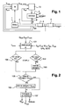
- the installation comprises an internal combustion engine 1, an exhaust manifold 2 channeling the exhaust gases to a nitrogen oxide trap 3, and a particulate filter 4 receiving the gases from the nitrogen oxide trap. 3.
- the installation further comprises a reformer 5 producing reformate from air and vehicle fuel such as diesel.
- a reformate pipe 8 channels the reformate to the exhaust manifold 2 upstream of the nitrogen oxide trap 3.
- the reformer 5 may be of any known type such as a steam reformer, by partial oxidation or by auto-thermal reforming.
- the reformer 5 includes a reformer calculator 10 which drives the reformer 5 to generate the desired rate of reformate with the desired richness.
- the installation also comprises an engine computer 9 which controls the engine 1, and in particular the fuel injection.
- the engine computer 9 receives information on the state or operation of the engine 1 from sensors. It further receives temperature information by temperature sensors such as thermocouples: an exhaust temperature Tech , measured in the exhaust manifold 2, a mixing temperature Tam upstream of the nitrogen oxide trap 3 and downstream of the reformate pipe inlet 8 in the exhaust manifold 2, and a temperature of the heated gases Tmes upstream of the particulate filter.
- the reformer calculator receives a reformate temperature Tref, measured in the reformate line 8.
- the reformer calculator 10 determines it is necessary to regenerate the particulate filter 4, it drives the reformer 5 for the latter to generate the reformate to be injected into the exhaust gas.
- the reformate passes through the nitrogen oxide trap 3 and undergoes oxidation with the oxygen contained in the exhaust gas.
- the oxidation is caused by the presence of catalysts in the nitrogen oxide trap 3, in a manner known per se.
- the oxidation causes the release of an amount of energy which serves to raise the temperature of the exhaust gas upstream of the particulate filter.
- the gases thus heated pass into the particle filter 4 and, because of their temperature, causes the regeneration of the particulate filter by the combustion of the soot trapped in the filter.
- a set temperature Tcons for the heated gases is predetermined, which makes it possible to obtain the regeneration without damaging the installation.
- ⁇ CO , ⁇ H2 , M ref can be determined by the reformer calculator 10 via stored mappings and taking as input the operating point of the reformer 5 as defined by the richness of the air / fuel mixture to be reformed and the reformate flow rate. It is the same for the heat capacities C ech , C ref of the exhaust gases and the reformate.
- step 102 determines whether the deviation coefficient is greater than a predetermined threshold value, for example 0.7.
- step 105 is directly entered. It also passes to this step after step 103. During step 105, it is determined whether the target flow rate exceeds a predetermined maximum flow rate Qmax according to the capacities of the installation. If this is the case, the flow rate calculated by the maximum flow rate Qmax is replaced in step 106 so as to limit the value of the setpoint.
- step 107 the setpoint flow is declined into a richness control and an airflow control for the reformer 5.
- one of the preceding commands can be combined with a fuel flow control, depending on the type of control accepted by the reformer 5.
- steps 101 to 107 are repeated in cycle as the regeneration is necessary.
- the invention is not limited to the embodiment described above solely by way of example.
- the nitrogen oxide trap may be replaced by other catalytic reformate oxidation means such as an oxidation catalyst.
- the set temperature Tcons may change during the regeneration.
Landscapes
- Engineering & Computer Science (AREA)
- Chemical & Material Sciences (AREA)
- Combustion & Propulsion (AREA)
- Mechanical Engineering (AREA)
- General Engineering & Computer Science (AREA)
- Chemical Kinetics & Catalysis (AREA)
- Exhaust Gas After Treatment (AREA)
- Processes For Solid Components From Exhaust (AREA)
- Exhaust-Gas Circulating Devices (AREA)
- Filtering Of Dispersed Particles In Gases (AREA)
- Output Control And Ontrol Of Special Type Engine (AREA)
Claims (8)
- Verfahren zum Steuern einer Anlage zum Behandeln der Abgase einer Brennkraftmaschine (1), wobei die Anlage Oxidationskatalysatormittel (3), einen stromabseitig der Oxidationskatalysatormittel (3) angeordneten Partikelfilter (4), Mittel zum Messen einer Temperatur Tmes der erwärmten Gase stromaufseitig des Partikelfilters (4), und einen Reformer (5), um ein Reformat zu erzeugen, enthält, wobei in dem Verfahren das Reformat zusammen mit den Abgasen stromaufseitig der Oxidationskatalysatormittel eingeleitet wird, um einen vorgegebenen Temperatursollwert Tcons der erwärmten Gase stromaufseitig des Partikelfilters (4) zu erhalten, derart, dass der Partikelfilter (4) durch Erhöhen der Temperatur regeneriert wird, dadurch gekennzeichnet, dass ein berechneter Durchsatz Qref_calc des Reformats als Funktion der Solltemperatur Tcons bestimmt wird, ein Abstandskoeffizient als Funktion der Differenz zwischen der Solltemperatur Tcons und der gemessenen Temperatur Tmes stromaufseitig des Partikelfilters bestimmt wird und der Reformer (5) mit einem Solldurchsatz Qref_cons des Reformats als Funktion des Abstandskoeffizienten α und des berechneten Durchsatzes Qref_calc des Reformats gesteuert wird, wobei der berechnete Durchsatz Qref_calc als Funktion der Veränderung der Enthalpie der Gase, die durch den Energieeintrag die Oxidation des Reformats bedingt ist, bestimmt wird.
- Verfahren nach Anspruch 1, wobei der berechnete Durchsatz durch die folgende Formel bestimmt wird:

worin:Qéch der Massendurchsatz der Abgase am Ausgang des Motors ist;Téch die Temperatur der Abgase ist;Céch die Massenwärmekapazität der Abgase ist;Tref die Temperatur des Reformats ist;Cref die Massenwärmekapazität des Reformats ist;ΔHH2 die Veränderung der Enthalpie bei der Oxidation eines Mols Wasserstoff ist;ΔHCO die Veränderung der Enthalpie bei der Oxidation eines Mols Kohlenstoffmonoxid ist;Tcons die Solltemperatur stromaufseitig des Partikelfilters ist;ηCO der molare Anteil von Kohlenstoffmonoxid im Reformat ist;ηH2 der molare Anteil von Wasserstoff im Reformat ist;Mref die molare Masse des Reformats ist. - Verfahren nach Anspruch 1, wobei der Abstandskoeffizient durch die folgende Formel bestimmt wird:
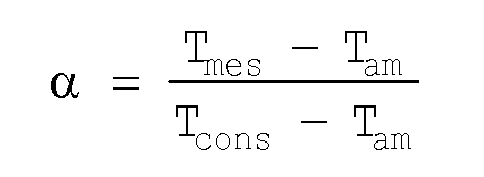
worin Tam die Temperatur des Gasgemisches stromaufseitig der Oxidationskatalysatormittel (3) ist. - Verfahren nach Anspruch 3, wobei der Solldurchsatz Qref_cons das Verhältnis des berechneten Durchsatzes Qref_calc zu dem Abstandkoeffizienten α ist.
- Verfahren nach Anspruch 4, wobei dann, wenn die gemessene Temperatur Tmes von der Solltemperatur Tcons stark abweicht, der Solldurchsatz der berechnete Durchsatz ist.
- Verfahren nach Anspruch 5, wobei davon ausgegangen wird, dass die gemessene Temperatur Tmes von der Solltemperatur Tcons stark abweicht, wenn der Abstandskoeffizient α kleiner als 0,7 ist.
- Verfahren nach Anspruch 1, wobei der Solldurchsatz Qref_cons durch einen vorgegebenen maximalen Durchsatzwert Qmax gedeckelt ist.
- Verfahren nach Anspruch 1, wobei die Oxidationskatalysatormittel einen Stickoxidabscheider (3) sind.
Applications Claiming Priority (2)
| Application Number | Priority Date | Filing Date | Title |
|---|---|---|---|
| FR0603632A FR2900196B1 (fr) | 2006-04-25 | 2006-04-25 | Procede de commande d'une installation de traitement des gaz d'echappement d'un moteur a combustion interne. |
| PCT/FR2007/050900 WO2007125228A1 (fr) | 2006-04-25 | 2007-03-09 | Procédé de commande d'une installation de traitement des gaz d'échappement d'un moteur à combustion interne |
Publications (2)
| Publication Number | Publication Date |
|---|---|
| EP2010765A1 EP2010765A1 (de) | 2009-01-07 |
| EP2010765B1 true EP2010765B1 (de) | 2011-01-05 |
Family
ID=37507331
Family Applications (1)
| Application Number | Title | Priority Date | Filing Date |
|---|---|---|---|
| EP07731716A Not-in-force EP2010765B1 (de) | 2006-04-25 | 2007-03-09 | Verfahren zur steuerung einer einrichtung zur behandlung von abgasen aus einer brennkraftmaschine |
Country Status (8)
| Country | Link |
|---|---|
| US (1) | US8156735B2 (de) |
| EP (1) | EP2010765B1 (de) |
| JP (1) | JP2009534586A (de) |
| KR (1) | KR20090014356A (de) |
| AT (1) | ATE494464T1 (de) |
| DE (1) | DE602007011742D1 (de) |
| FR (1) | FR2900196B1 (de) |
| WO (1) | WO2007125228A1 (de) |
Families Citing this family (7)
| Publication number | Priority date | Publication date | Assignee | Title |
|---|---|---|---|---|
| SG152955A1 (en) * | 2007-12-07 | 2009-06-29 | Inc Pte Ltd Agni | Integration of fuel cells, hydrogen reformer, fuel processor, absorption chiller, heat recovery steam generator and internal combustion engines |
| CN101878353B (zh) * | 2007-12-26 | 2012-09-05 | 丰田自动车株式会社 | 内燃机的排气净化装置 |
| EP2246534B1 (de) * | 2008-01-08 | 2013-10-16 | Honda Motor Co., Ltd. | Abgasreinigungsvorrichtung für einen verbrennungsmotor |
| JP5470136B2 (ja) * | 2010-03-31 | 2014-04-16 | 株式会社クボタ | ディーゼルエンジンの排気処理装置 |
| US20130139504A1 (en) * | 2011-12-01 | 2013-06-06 | GM Global Technology Operations LLC | Exahust system and method for controlling temperature of exhaust gas |
| KR20180102335A (ko) * | 2017-03-07 | 2018-09-17 | 주식회사 아모그린텍 | 배기가스를 이용하는 수소 개질기 |
| DE102018204456A1 (de) * | 2017-11-24 | 2019-05-29 | Fraunhofer-Gesellschaft zur Förderung der angewandten Forschung e.V. | Verfahren zum Betrieb eines katalytischen Verdampfers und Anwendungen des Verfahrens |
Family Cites Families (8)
| Publication number | Priority date | Publication date | Assignee | Title |
|---|---|---|---|---|
| JP3685052B2 (ja) * | 2000-11-30 | 2005-08-17 | 日産自動車株式会社 | 内燃機関の排気浄化装置 |
| DE10128414A1 (de) * | 2001-06-12 | 2002-12-19 | Daimler Chrysler Ag | Abgasreinigungsanlage mit Reduktionsmittelversorgung |
| US7021048B2 (en) * | 2002-01-25 | 2006-04-04 | Arvin Technologies, Inc. | Combination emission abatement assembly and method of operating the same |
| US6832473B2 (en) | 2002-11-21 | 2004-12-21 | Delphi Technologies, Inc. | Method and system for regenerating NOx adsorbers and/or particulate filters |
| FR2849468B1 (fr) * | 2002-12-30 | 2007-02-23 | Renault Sa | Systeme de depollution des gaz d'echappement pour un vehicule a moteur thermique |
| US7188469B2 (en) * | 2003-12-29 | 2007-03-13 | Delphi Technologies, Inc. | Exhaust system and methods of reducing contaminants in an exhaust stream |
| US20050274104A1 (en) * | 2004-06-15 | 2005-12-15 | Leslie Bromberg | Optimum regeneration of diesel particulate filters and NOx traps using fuel reformers |
| DE102004031321C5 (de) * | 2004-06-29 | 2020-06-25 | Robert Bosch Gmbh | Verfahren zum Dosieren eines Brennstoffs in einen Abgaskanal einer Brennkraftmaschine und Vorrichtung zur Durchführung des Verfahrens |
-
2006
- 2006-04-25 FR FR0603632A patent/FR2900196B1/fr not_active Expired - Fee Related
-
2007
- 2007-03-09 US US12/298,363 patent/US8156735B2/en not_active Expired - Fee Related
- 2007-03-09 KR KR1020087028688A patent/KR20090014356A/ko not_active Withdrawn
- 2007-03-09 EP EP07731716A patent/EP2010765B1/de not_active Not-in-force
- 2007-03-09 DE DE602007011742T patent/DE602007011742D1/de active Active
- 2007-03-09 AT AT07731716T patent/ATE494464T1/de not_active IP Right Cessation
- 2007-03-09 JP JP2009507121A patent/JP2009534586A/ja not_active Ceased
- 2007-03-09 WO PCT/FR2007/050900 patent/WO2007125228A1/fr not_active Ceased
Also Published As
| Publication number | Publication date |
|---|---|
| KR20090014356A (ko) | 2009-02-10 |
| FR2900196A1 (fr) | 2007-10-26 |
| ATE494464T1 (de) | 2011-01-15 |
| JP2009534586A (ja) | 2009-09-24 |
| US8156735B2 (en) | 2012-04-17 |
| DE602007011742D1 (de) | 2011-02-17 |
| FR2900196B1 (fr) | 2008-06-27 |
| US20090320455A1 (en) | 2009-12-31 |
| EP2010765A1 (de) | 2009-01-07 |
| WO2007125228A1 (fr) | 2007-11-08 |
Similar Documents
| Publication | Publication Date | Title |
|---|---|---|
| EP2010765B1 (de) | Verfahren zur steuerung einer einrichtung zur behandlung von abgasen aus einer brennkraftmaschine | |
| FR2899932A1 (fr) | Procede et dispositif de controle de la regeneration d'un systeme de depollution | |
| EP2106498B1 (de) | Verfahren zur steuerung der temperatur von abgasen in einem verbrennungsmotor | |
| EP2032811A1 (de) | Abgasleitung eines dieselmotors und entschwefelungsverfahren | |
| WO2008050051A1 (fr) | Procede de controle de la temperature des gaz dans un circuit d'echappement de moteur a combustion interne | |
| EP1836380A1 (de) | Verfahren und vorrichtung zur regeneration eines in einer abgasleitung eines verbrennungsmotors integrierten teilchenfilters | |
| EP2423477B1 (de) | Verfahren zur Feststellung des physikalischen Zustandes eines Partikelfilters | |
| FR2832184A1 (fr) | Systeme et procede de commande d'emission d'un moteur a combustion interne | |
| FR2879657A1 (fr) | Procede de gestion d'un moteur a combustion interne et dispositif pour la mise en oeuvre du procede | |
| EP2238334B1 (de) | Verfahren und vorrichtung zur wiederherstellung einer abgasnachbearbeitungsvorrichtung | |
| EP2877720B1 (de) | Abgasnachbehandlungssystem mit einem katalytischen partikelfilter und entsprechendes verfahren | |
| EP1277930B1 (de) | Verfahren und Vorrichtung zur Abgasemissionsreduzierung | |
| EP1413720B1 (de) | Verfahren zum Ermitteln der Innentemperatur eines Partikelfilters, Verfahren zur Steuerung der Regeneration des Partikelfilters, sowie Steuerungssystem und Partikelfilter | |
| FR2859240A1 (fr) | Procede de traitement d'un filtre a particules pour l'epuration de gaz d'echappement d'un moteur a combustion et dispositif de traitement d'un filtre a particules | |
| EP2718552B1 (de) | Verfahren zur regenerierung eines partikelfilters für ein kraftfahrfahrzeug | |
| FR2943095A1 (fr) | Procede de regeneration d'un filtre a particules | |
| EP1757353A1 (de) | Oxidationsverfahren zur Reinigung der Abgase eines Verbrennungsmotors und Vorrichtung zur Leistungsunterstützung eines Oxidationskatalysators | |
| FR3066704B1 (fr) | Procede de post-traitement des oxydes d'azote dans un moteur a combustion interne | |
| WO2009136029A1 (fr) | Procede de regeneration d'un systeme de post traitement par fractionnement de la richesse | |
| FR2943382A1 (fr) | Procede de gestion d'un piege a oxydes d'azote et dispositif de piege associe | |
| EP2084376A1 (de) | Mit verschmutzungsreduktionssystemen ausgestattetes verbrennungsmotorsystem | |
| FR2995638A1 (fr) | Alimentation en mode riche d'un moteur a combustion interne a derivation des gaz de suralimentation | |
| FR2856730A1 (fr) | Dispositif de postraitement de gaz d'echappement de moteur a allumage commande ou de bruleur par catalyse en deux etapes reduction puis oxydation | |
| FR2935020A1 (fr) | Procede pour la desulfuration d'un catalyseur d'oxydation apte a pieger des oxydes d'azote | |
| FR2948418A3 (fr) | Procede de gestion de la purge d'un piege a oxydes d'azote. |
Legal Events
| Date | Code | Title | Description |
|---|---|---|---|
| PUAI | Public reference made under article 153(3) epc to a published international application that has entered the european phase |
Free format text: ORIGINAL CODE: 0009012 |
|
| 17P | Request for examination filed |
Effective date: 20081023 |
|
| AK | Designated contracting states |
Kind code of ref document: A1 Designated state(s): AT BE BG CH CY CZ DE DK EE ES FI FR GB GR HU IE IS IT LI LT LU LV MC MT NL PL PT RO SE SI SK TR |
|
| AX | Request for extension of the european patent |
Extension state: AL BA HR MK RS |
|
| 17Q | First examination report despatched |
Effective date: 20100119 |
|
| GRAP | Despatch of communication of intention to grant a patent |
Free format text: ORIGINAL CODE: EPIDOSNIGR1 |
|
| GRAS | Grant fee paid |
Free format text: ORIGINAL CODE: EPIDOSNIGR3 |
|
| GRAA | (expected) grant |
Free format text: ORIGINAL CODE: 0009210 |
|
| AK | Designated contracting states |
Kind code of ref document: B1 Designated state(s): AT BE BG CH CY CZ DE DK EE ES FI FR GB GR HU IE IS IT LI LT LU LV MC MT NL PL PT RO SE SI SK TR |
|
| REG | Reference to a national code |
Ref country code: GB Ref legal event code: FG4D Free format text: NOT ENGLISH |
|
| REG | Reference to a national code |
Ref country code: CH Ref legal event code: EP |
|
| REG | Reference to a national code |
Ref country code: IE Ref legal event code: FG4D Free format text: LANGUAGE OF EP DOCUMENT: FRENCH |
|
| REF | Corresponds to: |
Ref document number: 602007011742 Country of ref document: DE Date of ref document: 20110217 Kind code of ref document: P |
|
| REG | Reference to a national code |
Ref country code: DE Ref legal event code: R096 Ref document number: 602007011742 Country of ref document: DE Effective date: 20110217 |
|
| REG | Reference to a national code |
Ref country code: NL Ref legal event code: VDEP Effective date: 20110105 |
|
| PG25 | Lapsed in a contracting state [announced via postgrant information from national office to epo] |
Ref country code: SI Free format text: LAPSE BECAUSE OF FAILURE TO SUBMIT A TRANSLATION OF THE DESCRIPTION OR TO PAY THE FEE WITHIN THE PRESCRIBED TIME-LIMIT Effective date: 20110105 |
|
| LTIE | Lt: invalidation of european patent or patent extension |
Effective date: 20110105 |
|
| PG25 | Lapsed in a contracting state [announced via postgrant information from national office to epo] |
Ref country code: GR Free format text: LAPSE BECAUSE OF FAILURE TO SUBMIT A TRANSLATION OF THE DESCRIPTION OR TO PAY THE FEE WITHIN THE PRESCRIBED TIME-LIMIT Effective date: 20110406 Ref country code: LV Free format text: LAPSE BECAUSE OF FAILURE TO SUBMIT A TRANSLATION OF THE DESCRIPTION OR TO PAY THE FEE WITHIN THE PRESCRIBED TIME-LIMIT Effective date: 20110105 Ref country code: PT Free format text: LAPSE BECAUSE OF FAILURE TO SUBMIT A TRANSLATION OF THE DESCRIPTION OR TO PAY THE FEE WITHIN THE PRESCRIBED TIME-LIMIT Effective date: 20110505 Ref country code: SE Free format text: LAPSE BECAUSE OF FAILURE TO SUBMIT A TRANSLATION OF THE DESCRIPTION OR TO PAY THE FEE WITHIN THE PRESCRIBED TIME-LIMIT Effective date: 20110105 Ref country code: LT Free format text: LAPSE BECAUSE OF FAILURE TO SUBMIT A TRANSLATION OF THE DESCRIPTION OR TO PAY THE FEE WITHIN THE PRESCRIBED TIME-LIMIT Effective date: 20110105 Ref country code: ES Free format text: LAPSE BECAUSE OF FAILURE TO SUBMIT A TRANSLATION OF THE DESCRIPTION OR TO PAY THE FEE WITHIN THE PRESCRIBED TIME-LIMIT Effective date: 20110416 Ref country code: IS Free format text: LAPSE BECAUSE OF FAILURE TO SUBMIT A TRANSLATION OF THE DESCRIPTION OR TO PAY THE FEE WITHIN THE PRESCRIBED TIME-LIMIT Effective date: 20110505 |
|
| REG | Reference to a national code |
Ref country code: IE Ref legal event code: FD4D |
|
| PG25 | Lapsed in a contracting state [announced via postgrant information from national office to epo] |
Ref country code: NL Free format text: LAPSE BECAUSE OF FAILURE TO SUBMIT A TRANSLATION OF THE DESCRIPTION OR TO PAY THE FEE WITHIN THE PRESCRIBED TIME-LIMIT Effective date: 20110105 Ref country code: BG Free format text: LAPSE BECAUSE OF FAILURE TO SUBMIT A TRANSLATION OF THE DESCRIPTION OR TO PAY THE FEE WITHIN THE PRESCRIBED TIME-LIMIT Effective date: 20110405 Ref country code: CY Free format text: LAPSE BECAUSE OF FAILURE TO SUBMIT A TRANSLATION OF THE DESCRIPTION OR TO PAY THE FEE WITHIN THE PRESCRIBED TIME-LIMIT Effective date: 20110105 Ref country code: FI Free format text: LAPSE BECAUSE OF FAILURE TO SUBMIT A TRANSLATION OF THE DESCRIPTION OR TO PAY THE FEE WITHIN THE PRESCRIBED TIME-LIMIT Effective date: 20110105 Ref country code: AT Free format text: LAPSE BECAUSE OF FAILURE TO SUBMIT A TRANSLATION OF THE DESCRIPTION OR TO PAY THE FEE WITHIN THE PRESCRIBED TIME-LIMIT Effective date: 20110105 Ref country code: PL Free format text: LAPSE BECAUSE OF FAILURE TO SUBMIT A TRANSLATION OF THE DESCRIPTION OR TO PAY THE FEE WITHIN THE PRESCRIBED TIME-LIMIT Effective date: 20110105 |
|
| BERE | Be: lapsed |
Owner name: RENAULT S.A.S. Effective date: 20110331 |
|
| PG25 | Lapsed in a contracting state [announced via postgrant information from national office to epo] |
Ref country code: IE Free format text: LAPSE BECAUSE OF FAILURE TO SUBMIT A TRANSLATION OF THE DESCRIPTION OR TO PAY THE FEE WITHIN THE PRESCRIBED TIME-LIMIT Effective date: 20110105 Ref country code: DK Free format text: LAPSE BECAUSE OF FAILURE TO SUBMIT A TRANSLATION OF THE DESCRIPTION OR TO PAY THE FEE WITHIN THE PRESCRIBED TIME-LIMIT Effective date: 20110105 Ref country code: MC Free format text: LAPSE BECAUSE OF NON-PAYMENT OF DUE FEES Effective date: 20110331 Ref country code: EE Free format text: LAPSE BECAUSE OF FAILURE TO SUBMIT A TRANSLATION OF THE DESCRIPTION OR TO PAY THE FEE WITHIN THE PRESCRIBED TIME-LIMIT Effective date: 20110105 |
|
| REG | Reference to a national code |
Ref country code: CH Ref legal event code: PL |
|
| PLBE | No opposition filed within time limit |
Free format text: ORIGINAL CODE: 0009261 |
|
| STAA | Information on the status of an ep patent application or granted ep patent |
Free format text: STATUS: NO OPPOSITION FILED WITHIN TIME LIMIT |
|
| PG25 | Lapsed in a contracting state [announced via postgrant information from national office to epo] |
Ref country code: SK Free format text: LAPSE BECAUSE OF FAILURE TO SUBMIT A TRANSLATION OF THE DESCRIPTION OR TO PAY THE FEE WITHIN THE PRESCRIBED TIME-LIMIT Effective date: 20110105 Ref country code: RO Free format text: LAPSE BECAUSE OF FAILURE TO SUBMIT A TRANSLATION OF THE DESCRIPTION OR TO PAY THE FEE WITHIN THE PRESCRIBED TIME-LIMIT Effective date: 20110105 Ref country code: CZ Free format text: LAPSE BECAUSE OF FAILURE TO SUBMIT A TRANSLATION OF THE DESCRIPTION OR TO PAY THE FEE WITHIN THE PRESCRIBED TIME-LIMIT Effective date: 20110105 |
|
| 26N | No opposition filed |
Effective date: 20111006 |
|
| PG25 | Lapsed in a contracting state [announced via postgrant information from national office to epo] |
Ref country code: BE Free format text: LAPSE BECAUSE OF NON-PAYMENT OF DUE FEES Effective date: 20110331 Ref country code: MT Free format text: LAPSE BECAUSE OF FAILURE TO SUBMIT A TRANSLATION OF THE DESCRIPTION OR TO PAY THE FEE WITHIN THE PRESCRIBED TIME-LIMIT Effective date: 20110105 Ref country code: IT Free format text: LAPSE BECAUSE OF FAILURE TO SUBMIT A TRANSLATION OF THE DESCRIPTION OR TO PAY THE FEE WITHIN THE PRESCRIBED TIME-LIMIT Effective date: 20110105 |
|
| PG25 | Lapsed in a contracting state [announced via postgrant information from national office to epo] |
Ref country code: LI Free format text: LAPSE BECAUSE OF NON-PAYMENT OF DUE FEES Effective date: 20110331 Ref country code: CH Free format text: LAPSE BECAUSE OF NON-PAYMENT OF DUE FEES Effective date: 20110331 |
|
| REG | Reference to a national code |
Ref country code: DE Ref legal event code: R097 Ref document number: 602007011742 Country of ref document: DE Effective date: 20111006 |
|
| PG25 | Lapsed in a contracting state [announced via postgrant information from national office to epo] |
Ref country code: LU Free format text: LAPSE BECAUSE OF NON-PAYMENT OF DUE FEES Effective date: 20110309 |
|
| PG25 | Lapsed in a contracting state [announced via postgrant information from national office to epo] |
Ref country code: TR Free format text: LAPSE BECAUSE OF FAILURE TO SUBMIT A TRANSLATION OF THE DESCRIPTION OR TO PAY THE FEE WITHIN THE PRESCRIBED TIME-LIMIT Effective date: 20110105 |
|
| PG25 | Lapsed in a contracting state [announced via postgrant information from national office to epo] |
Ref country code: HU Free format text: LAPSE BECAUSE OF FAILURE TO SUBMIT A TRANSLATION OF THE DESCRIPTION OR TO PAY THE FEE WITHIN THE PRESCRIBED TIME-LIMIT Effective date: 20110105 |
|
| REG | Reference to a national code |
Ref country code: FR Ref legal event code: PLFP Year of fee payment: 9 |
|
| REG | Reference to a national code |
Ref country code: FR Ref legal event code: PLFP Year of fee payment: 10 |
|
| PGFP | Annual fee paid to national office [announced via postgrant information from national office to epo] |
Ref country code: GB Payment date: 20160321 Year of fee payment: 10 Ref country code: FR Payment date: 20160321 Year of fee payment: 10 |
|
| PGFP | Annual fee paid to national office [announced via postgrant information from national office to epo] |
Ref country code: DE Payment date: 20160330 Year of fee payment: 10 |
|
| REG | Reference to a national code |
Ref country code: DE Ref legal event code: R119 Ref document number: 602007011742 Country of ref document: DE |
|
| GBPC | Gb: european patent ceased through non-payment of renewal fee |
Effective date: 20170309 |
|
| REG | Reference to a national code |
Ref country code: FR Ref legal event code: ST Effective date: 20171130 |
|
| PG25 | Lapsed in a contracting state [announced via postgrant information from national office to epo] |
Ref country code: DE Free format text: LAPSE BECAUSE OF NON-PAYMENT OF DUE FEES Effective date: 20171003 Ref country code: FR Free format text: LAPSE BECAUSE OF NON-PAYMENT OF DUE FEES Effective date: 20170331 |
|
| PG25 | Lapsed in a contracting state [announced via postgrant information from national office to epo] |
Ref country code: GB Free format text: LAPSE BECAUSE OF NON-PAYMENT OF DUE FEES Effective date: 20170309 |