EP2010757B1 - Turbinenschaufel - Google Patents
Turbinenschaufel Download PDFInfo
- Publication number
- EP2010757B1 EP2010757B1 EP07726359.8A EP07726359A EP2010757B1 EP 2010757 B1 EP2010757 B1 EP 2010757B1 EP 07726359 A EP07726359 A EP 07726359A EP 2010757 B1 EP2010757 B1 EP 2010757B1
- Authority
- EP
- European Patent Office
- Prior art keywords
- turbine blade
- blade
- medium
- trailing edge
- turbine
- Prior art date
- Legal status (The legal status is an assumption and is not a legal conclusion. Google has not performed a legal analysis and makes no representation as to the accuracy of the status listed.)
- Not-in-force
Links
- 238000002156 mixing Methods 0.000 claims description 43
- 239000000446 fuel Substances 0.000 claims description 18
- 238000007664 blowing Methods 0.000 claims description 8
- 238000011144 upstream manufacturing Methods 0.000 claims description 3
- 238000001816 cooling Methods 0.000 description 26
- 239000000203 mixture Substances 0.000 description 26
- 238000002485 combustion reaction Methods 0.000 description 15
- 239000002184 metal Substances 0.000 description 6
- 238000005266 casting Methods 0.000 description 5
- 206010016754 Flashback Diseases 0.000 description 3
- 230000000712 assembly Effects 0.000 description 3
- 238000000429 assembly Methods 0.000 description 3
- 238000004891 communication Methods 0.000 description 3
- 239000012530 fluid Substances 0.000 description 3
- 238000011065 in-situ storage Methods 0.000 description 3
- 239000000376 reactant Substances 0.000 description 3
- 239000000243 solution Substances 0.000 description 3
- 230000015572 biosynthetic process Effects 0.000 description 2
- 238000006243 chemical reaction Methods 0.000 description 2
- 239000002826 coolant Substances 0.000 description 2
- 238000013461 design Methods 0.000 description 2
- 210000003734 kidney Anatomy 0.000 description 2
- 238000000034 method Methods 0.000 description 2
- 230000010355 oscillation Effects 0.000 description 2
- 238000003303 reheating Methods 0.000 description 2
- 238000005476 soldering Methods 0.000 description 2
- 238000003466 welding Methods 0.000 description 2
- 239000000654 additive Substances 0.000 description 1
- 239000003795 chemical substances by application Substances 0.000 description 1
- 230000003247 decreasing effect Effects 0.000 description 1
- 238000009826 distribution Methods 0.000 description 1
- 230000000694 effects Effects 0.000 description 1
- 239000003344 environmental pollutant Substances 0.000 description 1
- 230000009969 flowable effect Effects 0.000 description 1
- 238000010438 heat treatment Methods 0.000 description 1
- 239000008240 homogeneous mixture Substances 0.000 description 1
- 238000002347 injection Methods 0.000 description 1
- 239000007924 injection Substances 0.000 description 1
- 238000003780 insertion Methods 0.000 description 1
- 230000037431 insertion Effects 0.000 description 1
- 238000009434 installation Methods 0.000 description 1
- 238000012423 maintenance Methods 0.000 description 1
- 238000004519 manufacturing process Methods 0.000 description 1
- 239000000463 material Substances 0.000 description 1
- 231100000719 pollutant Toxicity 0.000 description 1
- 238000002360 preparation method Methods 0.000 description 1
- 238000010926 purge Methods 0.000 description 1
- 230000035484 reaction time Effects 0.000 description 1
- 239000007787 solid Substances 0.000 description 1
- 125000006850 spacer group Chemical group 0.000 description 1
- 238000004804 winding Methods 0.000 description 1
Images


Classifications
-
- F—MECHANICAL ENGINEERING; LIGHTING; HEATING; WEAPONS; BLASTING
- F01—MACHINES OR ENGINES IN GENERAL; ENGINE PLANTS IN GENERAL; STEAM ENGINES
- F01D—NON-POSITIVE DISPLACEMENT MACHINES OR ENGINES, e.g. STEAM TURBINES
- F01D5/00—Blades; Blade-carrying members; Heating, heat-insulating, cooling or antivibration means on the blades or the members
- F01D5/12—Blades
- F01D5/14—Form or construction
- F01D5/141—Shape, i.e. outer, aerodynamic form
- F01D5/145—Means for influencing boundary layers or secondary circulations
-
- F—MECHANICAL ENGINEERING; LIGHTING; HEATING; WEAPONS; BLASTING
- F01—MACHINES OR ENGINES IN GENERAL; ENGINE PLANTS IN GENERAL; STEAM ENGINES
- F01D—NON-POSITIVE DISPLACEMENT MACHINES OR ENGINES, e.g. STEAM TURBINES
- F01D5/00—Blades; Blade-carrying members; Heating, heat-insulating, cooling or antivibration means on the blades or the members
- F01D5/12—Blades
- F01D5/14—Form or construction
- F01D5/18—Hollow blades, i.e. blades with cooling or heating channels or cavities; Heating, heat-insulating or cooling means on blades
- F01D5/186—Film cooling
-
- F—MECHANICAL ENGINEERING; LIGHTING; HEATING; WEAPONS; BLASTING
- F01—MACHINES OR ENGINES IN GENERAL; ENGINE PLANTS IN GENERAL; STEAM ENGINES
- F01D—NON-POSITIVE DISPLACEMENT MACHINES OR ENGINES, e.g. STEAM TURBINES
- F01D5/00—Blades; Blade-carrying members; Heating, heat-insulating, cooling or antivibration means on the blades or the members
- F01D5/12—Blades
- F01D5/14—Form or construction
- F01D5/18—Hollow blades, i.e. blades with cooling or heating channels or cavities; Heating, heat-insulating or cooling means on blades
- F01D5/187—Convection cooling
-
- F—MECHANICAL ENGINEERING; LIGHTING; HEATING; WEAPONS; BLASTING
- F01—MACHINES OR ENGINES IN GENERAL; ENGINE PLANTS IN GENERAL; STEAM ENGINES
- F01D—NON-POSITIVE DISPLACEMENT MACHINES OR ENGINES, e.g. STEAM TURBINES
- F01D9/00—Stators
- F01D9/06—Fluid supply conduits to nozzles or the like
- F01D9/065—Fluid supply or removal conduits traversing the working fluid flow, e.g. for lubrication-, cooling-, or sealing fluids
-
- F—MECHANICAL ENGINEERING; LIGHTING; HEATING; WEAPONS; BLASTING
- F02—COMBUSTION ENGINES; HOT-GAS OR COMBUSTION-PRODUCT ENGINE PLANTS
- F02C—GAS-TURBINE PLANTS; AIR INTAKES FOR JET-PROPULSION PLANTS; CONTROLLING FUEL SUPPLY IN AIR-BREATHING JET-PROPULSION PLANTS
- F02C3/00—Gas-turbine plants characterised by the use of combustion products as the working fluid
- F02C3/14—Gas-turbine plants characterised by the use of combustion products as the working fluid characterised by the arrangement of the combustion chamber in the plant
- F02C3/16—Gas-turbine plants characterised by the use of combustion products as the working fluid characterised by the arrangement of the combustion chamber in the plant the combustion chambers being formed at least partly in the turbine rotor or in an other rotating part of the plant
-
- F—MECHANICAL ENGINEERING; LIGHTING; HEATING; WEAPONS; BLASTING
- F02—COMBUSTION ENGINES; HOT-GAS OR COMBUSTION-PRODUCT ENGINE PLANTS
- F02K—JET-PROPULSION PLANTS
- F02K3/00—Plants including a gas turbine driving a compressor or a ducted fan
- F02K3/08—Plants including a gas turbine driving a compressor or a ducted fan with supplementary heating of the working fluid; Control thereof
-
- F—MECHANICAL ENGINEERING; LIGHTING; HEATING; WEAPONS; BLASTING
- F01—MACHINES OR ENGINES IN GENERAL; ENGINE PLANTS IN GENERAL; STEAM ENGINES
- F01D—NON-POSITIVE DISPLACEMENT MACHINES OR ENGINES, e.g. STEAM TURBINES
- F01D5/00—Blades; Blade-carrying members; Heating, heat-insulating, cooling or antivibration means on the blades or the members
- F01D5/12—Blades
- F01D5/14—Form or construction
- F01D5/18—Hollow blades, i.e. blades with cooling or heating channels or cavities; Heating, heat-insulating or cooling means on blades
- F01D5/187—Convection cooling
- F01D5/188—Convection cooling with an insert in the blade cavity to guide the cooling fluid, e.g. forming a separation wall
- F01D5/189—Convection cooling with an insert in the blade cavity to guide the cooling fluid, e.g. forming a separation wall the insert having a tubular cross-section, e.g. airfoil shape
-
- F—MECHANICAL ENGINEERING; LIGHTING; HEATING; WEAPONS; BLASTING
- F05—INDEXING SCHEMES RELATING TO ENGINES OR PUMPS IN VARIOUS SUBCLASSES OF CLASSES F01-F04
- F05D—INDEXING SCHEME FOR ASPECTS RELATING TO NON-POSITIVE-DISPLACEMENT MACHINES OR ENGINES, GAS-TURBINES OR JET-PROPULSION PLANTS
- F05D2240/00—Components
- F05D2240/10—Stators
- F05D2240/12—Fluid guiding means, e.g. vanes
- F05D2240/122—Fluid guiding means, e.g. vanes related to the trailing edge of a stator vane
-
- F—MECHANICAL ENGINEERING; LIGHTING; HEATING; WEAPONS; BLASTING
- F05—INDEXING SCHEMES RELATING TO ENGINES OR PUMPS IN VARIOUS SUBCLASSES OF CLASSES F01-F04
- F05D—INDEXING SCHEME FOR ASPECTS RELATING TO NON-POSITIVE-DISPLACEMENT MACHINES OR ENGINES, GAS-TURBINES OR JET-PROPULSION PLANTS
- F05D2240/00—Components
- F05D2240/10—Stators
- F05D2240/12—Fluid guiding means, e.g. vanes
- F05D2240/124—Fluid guiding means, e.g. vanes related to the suction side of a stator vane
-
- F—MECHANICAL ENGINEERING; LIGHTING; HEATING; WEAPONS; BLASTING
- F05—INDEXING SCHEMES RELATING TO ENGINES OR PUMPS IN VARIOUS SUBCLASSES OF CLASSES F01-F04
- F05D—INDEXING SCHEME FOR ASPECTS RELATING TO NON-POSITIVE-DISPLACEMENT MACHINES OR ENGINES, GAS-TURBINES OR JET-PROPULSION PLANTS
- F05D2250/00—Geometry
- F05D2250/20—Three-dimensional
- F05D2250/25—Three-dimensional helical
-
- F—MECHANICAL ENGINEERING; LIGHTING; HEATING; WEAPONS; BLASTING
- F05—INDEXING SCHEMES RELATING TO ENGINES OR PUMPS IN VARIOUS SUBCLASSES OF CLASSES F01-F04
- F05D—INDEXING SCHEME FOR ASPECTS RELATING TO NON-POSITIVE-DISPLACEMENT MACHINES OR ENGINES, GAS-TURBINES OR JET-PROPULSION PLANTS
- F05D2260/00—Function
- F05D2260/20—Heat transfer, e.g. cooling
- F05D2260/204—Heat transfer, e.g. cooling by the use of microcircuits
Definitions
- the invention relates to a turbine blade with a profiled, of a working gas flow around the airfoil, which has an approachable by the working gas leading edge and a trailing edge, at which the working gas can flow, and with a first channel system and with a second channel system for separately guiding two different, the Turbine blade separately fed media, wherein the first channel system in at least a first, arranged in the region of the trailing edge of the outlet opening for blowing out the first medium opens into the working gas.
- Such a turbine blade is for example from the WO 2005/3517 A1 known.
- the blade walls forming the airfoil surround an interior cavity in which cooling air can flow.
- further channels for guiding a second medium, namely fuel are provided in the blade wall of the turbine blade. Run through the blade wall of the turbine blade bores through which the flowing inside the turbine blade coolant can escape to the outside in a hot gas space.
- connecting channels are provided in the blade wall, which connect the fuel-carrying channels with the through-holes.
- both the hot gas flowing through the turbine and the cooling air flowing out of the turbine blade can be reheated by burning the mixture, which is generally used to increase the efficiency of the gas turbine, to reduce pollutant emissions and Improvement of the efficiency of the gas turbine is performed and is known as a form of Carnottician.
- a combustion chamber with a plurality of porous heat shield elements known by a combustible mixture subsequently, ie outside of burners of the gas turbine, can be introduced into the combustion chamber of a gas turbine.
- a turbine blade with a plurality of cooling channels arranged in the interior is known, which extend from the blade root to the blade tip and are also formed meander-shaped.
- the cooling channels are connected to a total of three foot-side openings for supplying cooling air of different quality.
- One of the openings is connected to a rectilinear, extending from the blade root to approximately the blade tip cavity. This cavity is immediately adjacent the trailing edge of the airfoil of the turbine blade and in fluid communication with the exit orifices located at the trailing edge.
- the coolant supplied through the corresponding foot-side opening can flow through the cavity and, via the outlet openings, leave it cooling over the approximately entire length of the trailing edge.
- the turbine blade has a further cavity, at the end of which a shovel tip is provided, a cooling channel extending transversely to the longitudinal extent of the blade is provided. This opens in the trailing edge only in the schaufelspitz solutionem area.
- in-situ blade reheat A disadvantage of the concepts known as "in-situ blade reheat" is that the mixing of cooling air and fuel in the components can ignite the reactants by autoignition or flashback. As a result, under certain circumstances, stable combustion processes are formed in the interior of the turbine blade, so that the cooling effect of the fuel-air mixture is lost or the component can be damaged by the internal combustion.
- the invention is based on the recognition that it is primarily necessary to separate the reactants, ie the two media, within the turbine blade and to avoid mixing within the volumes of the component, in order to prevent any occurring inside the turbine blade to prevent unwanted combustion safely. Likewise, it must be reliably avoided that the pressure prevailing in the working gas and possibly also the flow direction of the working gas can cause a flashback into the component. For this reason, the outlet openings, from which on the one hand the first medium, for example cooling air, and on the other hand the second medium, for example fuel, emerge, not transversely or open to the flow direction of the working gas, but they are arranged at the trailing edge of the turbine blade, so that the outflowing media have at least one rectified flow component in three-dimensional space as the working gas.
- the first medium for example cooling air
- the second medium for example fuel
- the reactants can only be mixed outside the turbine blade to form a possibly combustible mixture.
- the proposed solution also allows the rapid mixing of a first medium with a second medium, which thus resulting mixture is in turn mixed with the working gas of the turbine.
- the risk of flashback of a possibly combustible mixture is thus effectively prevented, since inside the turbine blade no combustible mixture of first and second medium occurs or can be blown back into the turbine blade due to the pressure in the working gas and / or its flow direction. Consequently, with the specified invention, a particularly safe turbine blade can be specified, in which a combustible mixture of the first medium and the second medium is not traceable.
- the working gas flowing in the turbine can be reheated reliably and without risk for a fire occurring in the interior of the turbine blade.
- the proposed turbine blade also for adding other fluid media as fuel or air within a turbine, regardless of whether gas or steam turbine, are used.
- one of the first outlet openings each with one of the second outlet openings forms - as seen along the blade main axis - overlapping pair of openings.
- Particularly preferred is the configuration of a turbine blade according to the invention, in which a plurality of pairs of juxtaposed openings follow one another along the trailing edge, so that over the entire height of the airfoil of the turbine blade, the two media can be blown out side by side.
- the first and the second outlet openings can also extend in each case over the entire height of the trailing edge.
- a first embodiment it is proposed that means are provided in the region of the trailing edge, which bring about a mixing of the first medium with the second medium immediately downstream of the outlet openings.
- the purging of both media takes place in a manner that causes a rapid mixing after their entry into the working gas space after the shortest distance and after a short time. This ensures that in the working gas chamber, an extremely homogeneous mixing of the two media takes place first and only then the after-heating of the working gas flowing through the turbine is mixed with this and ignited automatically due to the prevailing temperature in the working gas. This enables a particularly low-emission combustion of the combustible mixture produced in the first mixing step by premixing flames.
- the overall length of the turbine can also be shortened. Therefore, with the invention, a particularly compact and inexpensive to produce gas turbine can be specified, which is equipped with the turbine blades according to the invention.
- the agent causes a backflow-free mixing of the first medium with the second medium by at least one of the two or both media is at least approximately blown out at a sharp edge.
- the sharp edge generates backflow-free vortices, which due to their flow direction prevent the mixture from flowing back into the turbine blade.
- a return of the present in the working gas space mixture should be avoided anyway by pressure conditions in which the pressure prevailing at the outlet opening in the two media pressure is greater than the pressure of the working gas. A possibly taking place inside the turbine blade combustion process of the mixture can thus be effectively avoided, which maintains the life of the turbine blade.
- the means arranged in the trailing edge of the airfoil comprises at least one connection passage which connects at least one of the two duct systems with their associated outlet opening, the connection passage being such that it forms a swirl or vortex for the medium flowing through it impresses.
- the connecting passage connecting the channel system with the corresponding outlet opening therefore has a spatial shape which imparts to the medium flowing through it a swirl or vortex which continues after it leaves the outlet opening.
- the directions of the swirl or the vortices are chosen so that immediately after emerging from the outlet opening, the two media flow into one another and thus bring about their effective mixing. This results in a particularly homogeneous mixture and its particularly efficient and low-emission Combustion by a self-ignited premix flame. Consequently, the pollution caused by the gas turbine, in particular the NOx emissions, can be kept low.
- the connecting passages are coiled in the manner of a corkscrew, so that the media emerging through the outlet openings, this screw movement, d. H. their flow direction, after exiting trying to maintain.
- d. H. in a staggered arrangement of the corkscrew-like connecting passages in the manner of a double-threaded screw, two media can thus each be imparted with a swirl which, after their exit from the connecting passages, enables them to mix with each other in a particularly efficient manner.
- the means is provided in the outlet openings. Consequently, turbulators, dimples or the like may be provided in the outlet openings, and not only in the upstream connection channels, as the means which impart to the medium flowing through them a swirl or non-return vortex.
- a nozzle with a star-shaped circumferential contour is used as a separating element for the two media in a circular opening.
- One of the two media can flow out of the center of the nozzle and the other of the two media out of the cross-sectional area between the circular opening and the star-shaped contour. This nozzle-like design brings about a further improved mixing of the two outflowing media.
- the means for mixing the first medium with the second medium are provided on an inner side of the suction side and / or on an inner side of the pressure-side trailing edge wall of the blade, which trailing edge walls can flow around the working gas.
- the means provided in the outlet openings may also be a free-swinging tongue clamped on one side, which mixes the two media with each other in a particularly efficient manner due to their flow-excited oscillations.
- the blowing out of the two media takes place substantially or approximately parallel to the flow direction of the working gas, thorough mixing of the two media can still take place slightly within the turbine blade in the region of the trailing edge, without jeopardizing the non-return safety of the component.
- the mixing of the two media can be achieved by a field of pins and / or turbulators.
- the airfoil is cast and the means for mixing the two media is mounted as a separately produced insert in the airfoil.
- the structural features of the turbine blade proposed by the invention are particularly complicated to produce in the casting process. Therefore, the invention proposes to prefabricate these structures as a separately produced insert and then to fix it in the cast airfoil. As a result, a particularly inexpensive turbine blade can be specified.
- the invention also proposes a gas turbine which is equipped with a turbine blade according to the invention, wherein the advantages associated with the turbine blade can also be transferred to the gas turbine.
- FIG. 1 shows a schematic representation of a turbine blade, as used for example in one of the front stages of the turbine, for example, a stationary axial gas turbine.
- the turbine blade 10 is shown as a guide blade and, based on its installation position in the gas turbine, comprises an inner platform 12, an outer platform 14 and an airfoil 16 extending therebetween in the radial direction of the gas turbine.
- the outer platform 14 represents a foot region 13, where the turbine blade 10, for example on a vane carrier, can be attached.
- a head region 15 lying opposite the foot region 13 comprises the inner platform 12.
- the airfoil 16 is how FIG 2a to FIG 2c represent a curved in cross-section drop-shaped and extending from a front edge 18 to a trailing edge 20.
- a blade main axis 21 extends substantially parallel to the trailing edge 21 and along the radial direction of the gas turbine.
- the airfoil 16 having a height H is flowed around by a working gas 22, which first flows against the turbine blade 10 at the leading edge 18 and leaves the trailing edge 20 after the airfoil 16 flows around. Meanwhile, it flows along a ring-shaped working gas space 24, which is at least partially bounded radially inward by the inner platforms 12 and radially outward by the outer platforms 14 of the turbine blades 10.
- the airfoil 16 is hollow in its interior and has therein at least a first channel system 30 and a second channel system 40, which are formed separately from each other. In each channel system 30, 40 thus a medium M1 or M2 is separately feasible.
- the first medium M1 is supplied from the outside of the first channel system 30, for example, through the housing of the turbine from radially outside.
- the second medium M2, which is preferably not to mix within the turbine blade 10 with the first medium M1 is supplied via a separate feed line 32 of the turbine blade 10.
- the turbine blade 10 has a connection 34, to which the supply line 32 is connected in a gastight manner, for example by means of a seal 36 known from steam cooling.
- a pipe system 37 branches from the connection 34 in the interior.
- the second channel system 40 provided in the interior of the airfoil 16 for guiding the second medium M2 can be configured in different ways.
- Airfoil 16 shown in cross-section has a central cavity 38 provided as part of the first channel system 30 for guiding the first medium.
- the first channel system 30 comprises the entire cavity 38 of the turbine blade 10.
- Alternative embodiments are conceivable in which the cavity 38 can be subdivided into a plurality of regions by extending, for example, a rib 45 from the pressure-side wall 44 to the suction-side wall 42. This rib 45 is in FIG. 2a indicated in the region of the leading edge 18 by dashed lines.
- the first medium M1 flowing inside the first channel system 30, preferably cooling air, serves to cool the turbine blade 10, which after cooling has been blown out of the trailing edge 20 of the turbine blade 10 in the manner of an open cooling and is thus blown into the working gas 22 flowing approximately parallel ,
- the turbine blade 10 has a first connection passage 46, which opens into the first outlet opening 48 provided in the region of the trailing edge 20.
- the cavity 38 passes without an abutment into the first connection passage 46 and this into the first outlet opening 48 via.
- the second channel system 40 provided for carrying on the second medium M2 comprises a cavity 40 provided in the suction-side blade wall 42.
- the second channel system 40 was produced by means of a suitable casting core directly during the casting of the blade 16 and is fluidic via second connection passages 50 with second outlet openings 52 connected.
- the first channel system 30 and the second channel system 40 each extend over the radial direction of the gas turbine extending height H of the airfoil 16. At the trailing edge 20 of the turbine blade 10 is over the entire height H of the airfoil 16 extending first outlet opening 48 for the first medium M1 and a plurality of, along the height H uniformly distributed second outlet openings 52 provided for the second medium M2. It is also conceivable that a plurality of first outlet openings 48 and / or only a second outlet opening 52 are provided or is.
- both the first and second outlet openings 48, 52 are at least partially at the same radial height of the trailing edge 20 and thus overlap to a blowing of the two media M1, M2 as close to each other as possible to reach.
- FIG. 2b shows an alternative embodiment of the turbine blade 10 in cross section, in which the second channel system 40 for guiding the second medium M2 comprises a tube 60 inserted in the cavity 38 of the turbine blade 10.
- the tube 60 is connected via the height H of the airfoil 16 with the inner side 74 of the suction-side blade wall 42.
- FIG. 2b not shown connecting passages are analogous to those in.
- FIG. 2a shown turbine blade 10 for blowing out the medium M2 in the suction-side blade wall 42 already produced during casting or subsequently drilled and open on the one hand in the tube 60 and on the other hand in the outlet opening 52nd
- An impact cooling insert 62 required for impingement cooling of the blade walls 42, 44 is spaced from the inside 74 of the blade profile 16 by means of spacers 66 and shaped in cross-section so that it contributes to the formation of the first channel system 30 and the second channel system 40 inside the cavity 38 while the channels 30, 40 hermetically separated from each other.
- the second communication passages 50 may have been molded in the suction-side blade wall 42 of the turbine blade 10.
- the fuel guide is carried out in the embodiments described so far that parts of the second channel system 40, which may also be referred to as a fuel channel system, penetrate the turbine blade 10 in the radial direction and thereby either as cast into the blade wall 42, 44 channel ( FIG. 2a ), as a separate single or multiwalled tube ( FIG. 2b ) or as a separate fuel channel from the impact chiller ( 2c ) is formed.
- a fuel channel system which may also be referred to as a fuel channel system
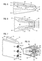
- FIG. 3 shows the perspective view of the trailing edge 20 of the airfoil 16 while blanking the outer and inner platform.
- the cavity 38 arranged inside the turbine blade 10, as part of the first channel system 30, merges into the first connection passage 46, which in turn merges into the first outlet opening 48, which is arranged in the trailing edge 22 of the turbine blade 10.
- second channels 40 are provided, which extend over the height of the blade 16.
- the second channels 40 are connected via second connecting passages 50 to the second outlet openings 52.
- mixer assemblies 70 for better mixing of the two outflowing media M1, M2.
- the mixing internals 70 are pyramid-shaped, designed as wedges or as tetrahedron 72, in whose rear, ie downstream, triangular surface in each case the second outlet opening 52 is provided.
- two tetrahedrons 72a, 72c are provided on the inner side 74 of the suction-side blade wall 42, the free tips of which face the inner side 76 of the pressure-side blade wall 44.
- the first medium M1 preferably cooling air, in a known manner, for example meandering, flowable, in the meantime to protect the material forming the blade 16 from thermal overloading. From there, it passes via the first connecting passages 46 to the first outlet opening 48.
- the second medium M2, preferably fuel, supplied to the second channels 40 is guided to the second outlet openings 52.
- FIG. 4 shows the cross section through the configuration of a turbine blade according to FIG. 3 in which the mutually offset tetrahedron 72, the suction-side blade wall 42, the pressure-side blade wall 44, the two first channels 30 and the two second channels 40 are shown.
- the tetrahedron 72 instead of the tetrahedron 72, other geometric shapes than mixer assemblies 70 are conceivable.
- FIG. 5 An alternative embodiment of the invention shows FIG. 5 in that the cavity 38 provided inside the turbine blade 10 for guiding cooling air is provided as the first medium M1.
- the second channel 40 is provided for guiding the second medium M2.
- At the trailing edge 20 are distributed over the height of the turbine blade 10 each outlet openings 48, 52 provided in pairs.
- Each first and each second outlet opening 48, 52 is connected in each case via its associated helical connection passage 50, 46 with the associated channel system 30, 40. In this case, two connection channels 46, 50 are always entwined in the manner of a double helix.
- the media M1, M2 flowing through the helically winding connecting passages 46, 50 also continue to flow after leaving the turbine blade 10 with the swirl imposed thereby.
- the connecting passages 46, 50 are aligned with one another such that after the exit of the two media M1, M2 from the outlet openings 48, 52 they flow into one another and thus bring about particularly efficient mixing within a particularly short mixing section and mixing time.
- This particularly efficient mixing is a prerequisite for the low-emission burning of the mixture with a short burn-out time after autoignition due to the temperature prevailing in the working gas 22 temperature.
- the working gas 22 or the cooling air flowing into the turbine is reheated, as a result of which its energy content can be increased and utilized as mechanical energy provided by the turbine. Furthermore, this increases the efficiency of the turbine.
- FIG. 6 shows a cross section through the trailing edge 20 of a modified turbine blade 10.
- the means of producing a particularly efficient mixing is one-sided
- the sheet metal element 80 is attached either to the inside 76 of the pressure-side paddle wall 44 or to the inside 74 of the suction-side wall 42, for example by welding or soldering, and vibrates during operation on the basis of FIG media M1, M2 flowing therealong between the two opposite inner sides 74, 76 of the pressure-side blade wall 44 and the suction-side blade wall 42 periodically back and forth, so that the outlet openings 48 and 52 mutually larger and smaller.
- the outflowing media M1, M2 swirl, so that downstream of the sheet metal element 80 a particularly efficient mixing of the two media M1, M2 takes place while achieving the aforementioned advantages.
- the free end 82 of the sheet metal part 80 is slightly thickened in cross section, so that it has an increased mass at this point. On the one hand, this facilitates the maintenance of the oscillation of the sheet metal element 80 and, on the other hand, serves to facilitate the generation of vertebrae, for example for producing Kármán vertebrae. It is not necessary that the free end 82 of the sheet metal element 80 comes to rest on the inner sides 74, 76 of the blade walls 42, 44 during the vibration process.
- FIG. 6 Another advantage of in FIG. 6 As shown, when the medium M2 is suppressed, the channel system 40 is separable from the working gas space 24, since the pressure prevailing in the working gas 22 or in the medium M1 presses the sheet metal element 80 against the inside 74 of the suction side vane wall 42. The otherwise caused by the medium M2 back pressure is missing in this case. The outlet opening 52 is then closed and thus protected against prestigegaseinzug.
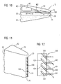
- FIG. 9 show in different views, the trailing edge 20 of the turbine blade 10 with nozzle-shaped outlet openings 48, 52.
- the insert 90 has, as in FIG. 9 represented on the outflow side - with respect to the flow direction of the two media M1, M2 - a circumferential contour 96 in the manner of a star.
- a substantially simpler contour 98 for example that of a rectangle, is provided.
- the area enclosed by the star-shaped circumferential contour 96 of the insert 90 forms the first outlet opening 48.
- the area lying between the circular contour 93 of the opening 92 and the area outside the star-shaped contour 96 then forms the second outlet opening 52.
- the turbine blade 10 in the region of the trailing edge 20 according to FIG. 8 with two respectively provided in the blade walls 42, 44 second channels 40 and with the introduced in the trailing edge opening 92 can with a according to FIG. 9 configured and inserted into the opening 92 insert 90 a particularly simple turbulence of the two flowing out of the trailing edge 20 of the turbine blade 10 media M1, M2 can be achieved.
- the first medium M1 preferably cooling air, and is guided due to the changing along the flow direction contour of the insert 90 according to this.
- the outflow-side contour 96 of the insert 90 with fingers 94 protruding in a star shape causes the medium M2, which is supplied from the second connection passages 50, to flow into the intermediate spaces 99 lying between the fingers 94.
- This design also referred to as a flower mixer, also has extremely intensive mixing rates.
- FIG. 10 to FIG. 12 show a further embodiment of the invention, in which in the region of the trailing edge 20 over the height H a wave-like insert 100 for generating turbulence in the outflowing media M1, M2 is provided.
- the trailing edge 20 has a rectangular slot 102 extending over its height H, which is bisected by an insert 100 inserted therein over its height.
- the insert 100 is spaced from the two inner sides 74, 76 of the blade walls 42, 44, with the spacing between each inner wall 74, 76 and insert 10 periodically increasing and decreasing due to the waveform of the insert 100 as seen along the trailing edge 20.
- the wavefront 104 of the insert 100 which is provided as means for generating swirls, is inclined with respect to the flow direction of the media M1, M2, so that the media M1, M2 guided on both sides of the insert 100 flow across the swirls of the insert 100 and are swirled by them; so that a homogeneous mixing of the two media M1, M2 takes place downstream of the insert 100.
- the resulting mixture heats working gas 22 after or can also serve for the emission treatment of the working gas 22.
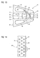
- FIG. 13 and FIG. 14 10 show an alternative embodiment in which only the first medium M1 guided through the first connection passages 46 form a series of vortex streets due to staggered pins 110 which extend from the inside 76 of the pressure-side blade wall 44 to the inside 74 of the suction-side blade wall 42 is swirled.
- the blowing out of the second medium M2 from the turbine blade 10 into the swirling first medium M1 is effected by second outlet openings 52 provided at the trailing edge 20 whose upstream second connecting passages 50 are rectilinear but inclined towards the outer or inner platform.
- the means for generating turbulence in the medium M1 is the field of pins 110 provided in the first connection passage 46.
- the pins 110 may be provided on the inner sides 74, 76 and dimples, turbulators or grooves.
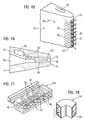
- a further embodiment of the invention is in the FIG. 15 to FIG. 17 4, in which a substantially solid and in its dimensions rectangular insert 120 is inserted into a slot 122 provided in the trailing edge 20 of the turbine blade 10, with which the turbulence of the two media M1, M2 flowing out at this point is brought about.
- the in FIG. 17 insert 120 shown in perspective is equipped with a plurality of mutually parallel first connecting passages 46, which extend transversely to the second connecting passages 50.
- First and second communication passages 46, 50 intersect each other without being connected to each other at the intersections and open into pairs coincident outlets 48, 52, where the mixing of the two media M1, M2 takes place. Due to the obliquely lying outflow directions of the two media M1, M2 they are efficiently swirled and mixed with each other within a short mixing section.
- Parallel to the outwardly and inwardly inclined to the platforms connecting passages 46, 50 may be provided on the working gas 22 facing surface of the blade walls 42, 44, preferably in the region of the trailing edge 20 as well as swirling elements in the form of grooves or dimples that the working gas 22 additionally swirl.
- FIG. 18 shows a perspective view of a tubular, rectangular in flow cross-section insert 130, which has means for the production of kidney vertebrae 132 inside.
- the introduced into the kidney fluid stream other medium is mixed particularly evenly with the one medium due to the turbulence.
- a turbine equipped with such a turbine blade is particularly suitable for manipulating the working medium flowing into it by supplying additional media.
- the energy content of the working medium can be increased by "in-situ blade reheat" or the emission load of the working medium can be lowered by the addition of additives.
- the invention proposes a trailing edge of a turbine blade, by means of which two media guided inside the turbine blade are added to the working gas in such a way that they first mix with one another before the mixture or one of the media reacts only partially with the working gas.
- means for swirling or twisting of the flows are provided, whereby, in the case of a combustible mixture, a particularly low-emission combustion of the mixture for reheating the working gas due to a particularly short mixing section and a short Mixing time in time, even before leaving the turbine, can be achieved.
Landscapes
- Engineering & Computer Science (AREA)
- Mechanical Engineering (AREA)
- General Engineering & Computer Science (AREA)
- Chemical & Material Sciences (AREA)
- Combustion & Propulsion (AREA)
- Physics & Mathematics (AREA)
- Fluid Mechanics (AREA)
- Turbine Rotor Nozzle Sealing (AREA)
Description
- Die Erfindung betrifft eine Turbinenschaufel mit einem profilierten, von einem Arbeitsgas umströmbaren Schaufelblatt, welches eine vom Arbeitsgas anströmbare Vorderkante aufweist sowie eine Hinterkante, an der das Arbeitsgas abströmbar ist, und mit einem ersten Kanalsystem und mit einem zweiten Kanalsystem zum getrennten Führen zweier unterschiedlicher, der Turbinenschaufel getrennt zuführbaren Medien, wobei das erste Kanalsystem in mindestens einer ersten, im Bereich der Hinterkante angeordneten Austrittsöffnung zum Ausblasen des ersten Mediums in das Arbeitsgas mündet.
- Eine derartige Turbinenschaufel ist beispielsweise aus der
WO 2005/3517 A1 - Außerdem ist aus der
WO 99/46540 A1 - Aus der
EP 0 896 127 A2 ist eine Turbinenschaufel mit einer Vielzahl von im Inneren angeordneten Kühlkanälen bekannt, die sich vom Schaufelfuß zur Schaufelspitze hin erstrecken und dabei auch mäanderförmig ausgebildet sind. Die Kühlkanäle sind mit insgesamt drei fußseitigen Öffnungen zum Zuführen von Kühlluft unterschiedlicher Qualität verbunden. Eine der Öffnungen ist mit einem geradlinigen, sich vom Schaufelfuß bis annähernd zur Schaufelspitze erstreckenden Hohlraum verbunden. Dieser Hohlraum ist unmittelbar zur Hinterkante des Schaufelblatts der Turbinenschaufel benachbart und steht mit den an der Hinterkante angeordneten Austrittsöffnungen in Strömungsverbindung. Das durch die entsprechende fußseitige Öffnung zugeführte Kühlmittel kann den Hohlraum durchströmen und über die Austrittsöffnungen über die annähernd gesamte Länge der Hinterkante diese dabei kühlend verlassen. Zugleich weist die Turbinenschaufel einen weiteren Hohlraum auf, an dessen schaufelspitzseitigem Ende sich ein quer zur Längserstreckung des Schaufelblatts erstreckender Kühlkanal vorgesehen ist. Dieser mündet in der Hinterkante lediglich in dessen schaufelspitzseitigem Bereich. - Des Weiteren ist aus der
US 6,551,063 bekannt, die Hinterkante einer Turbinenschaufel modular auszuführen, indem bei einer Turbinenschaufel mit einer so genannten "cut back"-Hinterkante eine die Hinterkantenrippen überdeckendes blechartiges Element angelötet oder angeschweißt wird. - Nachteilig an den auch als "in-situ blade reheat" bekannten Konzepten ist, dass durch die Vermischung von Kühlluft und Brennstoff in den Bauteilen sich die Reaktionspartner durch Selbstzündung oder Flammenrückschlag entzünden können. Hierdurch bilden sich unter Umständen stabile Verbrennungsvorgänge in Inneren der Turbinenschaufel aus, so dass die Kühlwirkung des Brennstoff-Luftgemisches verloren geht, bzw. das Bauteil durch die intern auftretende Verbrennung Schaden nehmen kann.
- Es ist daher die Aufgabe der Erfindung, eine Turbinenschaufel für eine Gasturbine bereitzustellen, bei der eine im Inneren stattfindende Verbrennung zur Erhaltung der Lebensdauer der Turbinenschaufel und zur Vermeidung von Schäden in der Gasturbine sicher vermieden wird.
- Die Lösung dieser Aufgabe wird mit einer gattungsgemäßen Turbinenschaufel gemäß Anspruch 1 erzielt.
- Die Erfindung geht von der Erkenntnis aus, dass es primär notwendig ist, die Reaktionspartner, d. h. die beiden Medien, innerhalb der Turbinenschaufel getrennt zu führen und eine Vermischung innerhalb des Volumina des Bauteils zu vermeiden, um eine im Inneren der Turbinenschaufel ggf. stattfindende ungewollte Verbrennung sicher zu verhindern. Ebenso muss sicher vermieden werden, dass der im Arbeitsgas herrschende Druck und ggf. auch die Strömungsrichtung des Arbeitsgases einen Flammenrückschlag ins Bauteil herbeiführen können. Aus diesem Grund sind die Austrittsöffnungen, aus denen einerseits das erste Medium, beispielsweise Kühlluft, und andererseits das zweite Medium, beispielsweise Brennstoff, austreten, nicht quer oder zur Strömungsrichtung des Arbeitsgases hin geöffnet, sondern sie sind an der Hinterkante der Turbinenschaufel angeordnet, so dass die ausströmenden Medien mindestens eine gleichgerichtete Strömungskomponente im dreidimensionalen Raum aufweisen wie das Arbeitsgas.
- Da beide Medien an der Hinterkante aus dem Bauteil ausgeblasen und in das Arbeitsgas eingeblasen werden, können sich die Reaktionspartner erst außerhalb der Turbinenschaufel zu einem ggf. brennbaren Gemisch vermischen. Die vorgeschlagene Lösung ermöglicht außerdem die schnelle Vermischung von einem ersten Medium mit einem zweiten Medium, welches so entstandene Gemisch wiederum dem Arbeitsgas der Turbine untergemischt wird. Die Gefahr von Rückzündungen eines evtl. brennbaren Gemisches wird somit wirksam verhindert, da im Inneren der Turbinenschaufel kein brennbares Gemisch aus erstem und zweitem Medium auftritt oder aufgrund des Druckes im Arbeitsgas und/oder dessen Strömungsrichtung zurück in die Turbinenschaufel eingeblasen werden kann. Folglich kann mit der angegebenen Erfindung eine besonders sichere Turbinenschaufel angegeben werden, in welche ein brennbares Gemisch aus erstem Medium und zweitem Medium nicht zurückführbar ist. Eine Selbstzündung des Gemischs innerhalb der Turbinenschaufel kann unter Aufrechterhaltung der Lebensdauer der Turbinenschaufel sicher vermieden werden. In einer mit der erfindungsgemäßen Turbinenschaufel ausgestatteten Turbine kann das in der Turbine strömende Arbeitsgas zuverlässig und risikolos im Hinblick auf einen durch im Inneren der Turbinenschaufel stattfindenden Brand nachgeheizt werden.
- Die Rückschlagssicherheit wird vor allen Dingen dadurch sichergestellt, dass der Brennstoff nahe der Hinterkante im Bereich gerichteter Arbeitgasströmung, d.h. mit zwei identischen Strömungsrichtungskomponenten und ohne Ausbildung von Rückströmzonen eingedüst wird. Es treten somit keine durch Strömungswirbel verursachten Verweilzeitverteilungen auf, die eine Verbrennung im Inneren der Turbineschaufel hervorgerufen können.
- Selbstverständlich kann die vorgeschlagene Turbinenschaufel auch zur Zugabe anderer fluider Medien als Brennstoff oder Luft innerhalb einer Turbine, unabhängig davon ob Gas- oder Dampfturbine, eingesetzt werden.
- Eine äußerst effiziente, emissionsarme Verbrennung des Brennstoff im Arbeitsgas kann erreicht werden, wenn sich die Hinterkante entlang einer Schaufelblatthauptachse von einem Fußbereich des Schaufelblattes zu einem diesem gegenüberliegenden Kopfbereich erstreckt, wobei entlang der Schaufel-blatthauptachse betrachtet die zweite Austrittsöffnung zumindest teilweise auf der gleichen Höhe angeordnet ist wie die erste Austrittsöffnung. Somit ist es erstmalig möglich, dass durch die Hinterkante auf einer radialen Höhe des ringkanalförmigen Arbeitsgasraumes der Gasturbine sowohl Brennstoff als auch Verbrennungsluft gleichzeitig in das Arbeits-gas eindüsbar ist, um eine besonders effiziente Verbrennung zu erreichen. Folglich liegen die erste Austrittsöffnung und die zweite Austrittsöffnung in Richtung der Schaufelblatthauptachse gesehen, nicht hintereinander, sondern überlappend nebeneinander.
- Um eine besonders gut aufeinander abgestimmte Menge von erstem und zweitem Medium innerhalb eines vergleichsweise schmalen Abschnittes der Hinterkante in das Arbeitsgas einzudüsen, bildet jeweils eine der ersten Austrittsöffnungen mit jeweils einer der zweiten Austrittsöffnungen ein - entlang der Schaufelblatthauptachse gesehen - sich überlappendes Paar von Öffnungen. Besonders bevorzugt ist dabei die Ausgestaltung einer erfindungsgemäßen Turbinenschaufel, bei der mehrere Paare von nebeneinander angeordneten Öffnungen entlang der Hinterkante aufeinander folgen, so dass über die gesamte Höhe des Schaufelblattes der Turbinenschaufel das nebeneinander Ausblasen der beiden Medien erfolgen kann. Um dies zu erreichen, können sich alternativ zur vorgenannten Lösung die erste und die zweite Austrittsöffnung auch jeweils über die gesamte Höhe der Hinterkante erstrecken.
- In einer ersten Ausgestaltung wird vorgeschlagen, dass im Bereich der Hinterkante Mittel vorgesehen sind, welche eine Vermischung des ersten Mediums mit dem zweiten Medium unmittelbar stromab der Austrittsöffnungen herbeiführen. Die Ausblasung beider Medien erfolgt in einer Art und Weise, die eine schleunigste Vermischung nach ihrem Eintritt in den Arbeitsgasraum nach kürzester Strecke und nach kürzester Zeit bedingt. Damit wird sichergestellt, dass im Arbeitsgasraum zuerst eine äußerst homogene Vermischung der beiden Medien erfolgt und erst im Anschluss daran das zur Nachheizung des die Turbine durchströmenden Arbeitsgases mit diesem vermischt und aufgrund der im Arbeitsgas herrschenden Temperatur selbsttätig entzündet wird. Dies ermöglicht eine besonders emissionsarme Verbrennung des im ersten Vermischungsschritt hergestellten brennbaren Gemischs durch Vormischflammen.
- Durch die Vermischung innerhalb einer kurzen Reaktionsstrecke und Reaktionszeit wird außerdem erreicht, dass das Gemisch noch vor dem Verlassen des ringkanalförmigen Arbeitsgasraumes verbrennt, da die durch die Nachheizung des Arbeitsgases stattfindende Energieerhöhung des Arbeitsgases nur dann zur Leistungssteigerung und Wirkungsgradsteigerung der Turbine beträgt, wenn das nachgeheizte Arbeitsgas noch an den Laufschaufeln der Turbine zur Umsetzung der Strömungsenergie in mechanische Energie vorbeiströmt.
- Durch die kurze Reaktionsstrecke kann sich ferner die Baulänge der Turbine verkürzen. Daher kann mit der Erfindung auch eine besonders kompakte als auch kostengünstig herzustellende Gasturbine angegeben werden, welche mit den erfindungsgemäßen Turbinenschaufeln ausgestattet ist.
- Darüber hinaus wird vorgeschlagen, dass das Mittel eine rückströmfreie Vermischung des ersten Mediums mit dem zweiten Medium hervorruft, indem mindestens eines der beiden oder beide Medien zumindest annähernd an einer scharfen Kante ausgeblasen wird. Durch die scharfe Kante werden rückströmfreie Wirbel erzeugt, die aufgrund ihrer Strömungsrichtung verhindern, dass das Gemisch in die Turbinenschaufel zurückströmt. Außerdem soll ein Zurückführen des im Arbeitsgasraum vorliegenden Gemischs ohnehin durch Druckverhältnisse vermieden werden, bei denen der an der Austrittsöffnung in den beiden Medien herrschende Druck größer ist als der Druck des Arbeitsgases. Ein im Inneren der Turbinenschaufel möglicherweise stattfindender Verbrennungsvorgang des Gemischs kann somit wirksam vermieden werden, was die Lebensdauer der Turbinenschaufel aufrechterhält.
- Es wird ferner vorgeschlagen, dass das in der Hinterkante des Schaufelblatts angeordnete Mittel mindestens eine Verbindungspassage umfasst, welche mindestens eines der beiden Kanalsysteme mit der ihr zugeordneten Austrittsöffnung verbindet, wobei die Verbindungspassage der Gestalt ist, dass diese dem durch sie strömenden Medium einen Drall oder Wirbel aufprägt. Die das Kanalsystem mit der korrespondierenden Austrittsöffnung verbindende Verbindungspassage weist somit eine räumliche Gestalt auf, die dem durch sie strömendem Medium einen Drall oder Wirbel aufprägt, der sich nach ihrem Austreten aus der Austrittsöffnung fortsetzt. Die Richtungen des Dralls bzw. der Wirbel sind so gewählt, dass unmittelbar nach dem Austreten aus der Austrittsöffnung die beiden Medien ineinander strömen und so ihre wirksame Vermischung herbeiführen. Dies führt zu einem besonders homogenen Gemisch und zu dessen besonders effizienten und emissionsarmen Verbrennung durch eine sich selbst entzündete Vormischflamme. Folglich kann die durch die Gasturbine hervorgerufene Schadstoffbelastung, insbesondere die NOx-Emissionen, gering gehalten werden.
- Beispielsweise sind die Verbindungspassagen nach Art eines Korkenziehers gewendelt, so dass die durch die Austrittsöffnungen austretenden Medien diese Schraubenbewegung, d. h. ihre Strömungsrichtung, nach dem Austritt versuchen aufrecht zu erhalten. Bei geeigneter, d. h. bei versetzter Anordnung der korkenziehartig ausgeprägten Verbindungspassagen nach Art einer zweigängigen Schraube, kann beiden Medien somit jeweils ein Drall aufgeprägt werden, der diesen nach ihrem Austritt aus den Verbindungspassagen eine besonders effiziente Durchmischung miteinander ermöglicht.
- In einer weiteren vorteilhaften Ausgestaltung wird vorgeschlagen, dass das Mittel in den Austrittsöffnungen vorgesehen ist. Folglich können selber in den Austrittsöffnungen, und nicht nur in den vorgeordneten Verbindungskanälen, Turbulatoren, Dimpel oder ähnliches als das Mittel vorgesehen sein, die dem durch sie ausströmenden Medium einen Drall oder rückströmfreien Wirbel aufprägen. Vorzugsweise ist in einer kreisrunden Öffnung eine Düse mit einer sternförmig umlaufenden Kontur als Trennelement für die beiden Medien eingesetzt. Aus dem Zentrum der Düse kann eines der beiden Medien ausströmen und aus der Querschnittsfläche zwischen der kreisrunden Öffnung und der sternförmigen Kontur das andere der beiden Medien. Diese düsenartige Ausgestaltung führt eine weiter verbesserte Durchmischung der beiden ausströmenden Medien herbei.
- Ferner wird mit der Erfindung vorgeschlagen, dass die Mittel zum Vermischen des ersten Mediums mit dem zweiten Medium an einer Innenseite der saugseitigen und/oder an einer Innenseite der druckseitigen Hinterkantenwand des Schaufelblatts vorgesehen sind, welche Hinterkantenwände vom Arbeitsgas umströmbar ist/sind.
- Das in den Austrittsöffnungen vorgesehene Mittel kann auch eine frei schwingende, einseitig eingespannte Zunge sein, die durch ihre strömungsangeregten Schwingungen die beiden Medien miteinander besonders effizient vermischt.
- Wenn die Ausblasung der beiden Medien im Wesentlichen oder annähernd parallel zur Strömungsrichtung des Arbeitsgases erfolgt, kann eine Durchmischung der beiden Medien noch geringfügig innerhalb der Turbinenschaufel im Bereich der Hinterkante stattfinden, ohne die Rückschlagsicherheit des Bauteils zu gefährden. Beispielsweise kann die Durchmischung der beiden Medien durch ein Feld von Pins und/oder Turbulatoren erreicht werden.
- Es wird ferner vorgeschlagen, dass das Schaufelblatt gegossen ist und das Mittel zum Vermischen der beiden Medien als separat hergestellter Einsatz in dem Schaufelblatt befestigt ist. Üblicherweise sind die mit der Erfindung vorgeschlagenen strukturellen Merkmale der Turbinenschaufel im Gussverfahren besonders aufwendig herzustellen. Daher schlägt die Erfindung vor, diese Strukturen als separat hergestellter Einsatz vorzufertigen und anschließend in dem gegossenen Schaufelblatt zu befestigen. Hierdurch kann eine besonders kostengünstige Turbinenschaufel angegeben werden.
- Die Erfindung schlägt auch eine Gasturbine vor, welche mit einer erfindungsgemäßen Turbinenschaufel ausgestattet ist, wobei sich die mit der Turbinenschaufel einhergehenden Vorteile auch auf die Gasturbine übertragen lassen.
- Weitere Vorteile und Merkmale sind der folgenden Beschreibung von Ausführungsbeispielen zu entnehmen. Im Wesentlichen gleich bleibende Elemente sind mit den gleichen Bezugszeichen bezeichnet. Ferner wird bezüglich gleicher Merkmale und Funktionen auf die Beschreibung zum Ausführungsbeispiel verwiesen. Es zeigen:
- FIG 1
- eine schematische Darstellung einer Turbinenschaufel mit einer Zuleitung für Brennstoff,
- FIG 2a
- einen Querschnitt durch das Schaufelblatt der Turbinenschaufel mit einem in einer Schaufelwand eingegossenen Kanalsystem zum Führen eines zweiten Mediums,
- FIG 2b
- einen Querschnitt durch das Schaufelblatt der Turbinenschaufel mit einem von einem rohrartigen Einsatz gebildeten Kanalsystem zum Führen des zweiten Mediums,
- FIG 2c
- einen Querschnitt durch das Schaufelblatt der Turbinenschaufel mit einem von einem Prallkühlblech umschlossenen Kanalsystem zum Führen des zweiten Mediums,
- FIG 3
- eine perspektivische Ansicht auf die Hinterkante des Schaufelblatts der Turbinenschaufel,
- FIG 4
- den Querschnitt durch die Schaufelhinterkante gemäß
FIG 3 , - FIG 5
- den Querschnitt durch die Hinterkante der Turbinenschaufel mit sich nach Art einer Doppelhelix ineinander windenden Verbindungspassagen,
- FIG 6
- den Querschnitt durch die Hinterkante der Turbinenschaufel mit einem in der Hinterkante befestigten beweglichen Element,
- FIG 7
- die perspektivische Ansicht der Hinterkante der Turbinenschaufel mit im Bereich der Hinterkante angeordneten Düsen,
- FIG 8
- den Querschnitt durch die Hinterkante der Turbinenschaufel gemäß
FIG 7 mit der daran angeordneten düsenförmigen Austrittsöffnung, - FIG 9
- die in der Hinterkante der Turbinenschaufel gemäß
FIG 7 befestigbare Düse in perspektivischer Darstellung, - FIG 10
- den Querschnitt durch die Hinterkante der Turbinenschaufel mit einem wellenartigen Einsatz,
- FIG 11
- die Hinterkante der Turbinenschaufel mit dem wellenartigen Einsatz,
- FIG 12
- den wellenartigen Einsatz für eine Turbinenschaufel gemäß
FIG 11 , - FIG 13
- einen Querschnitt durch die Hinterkante der Turbinenschaufel mit einem in der Hinterkante angeordnetem Feld aus Pins,
- FIG 14
- den Längsschnitt durch die Turbinenschaufel gemäß
FIG 13 im Bereich der Hinterkante, - FIG 15
- in perspektivischer Darstellung die Hinterkante der Turbinenschaufel mit einer kreuzweisen Ausblasung,
- FIG 16
- den Querschnitt durch die Hinterkante der Turbinenschaufel mit einer kreuzweisen Ausblasung gemäß
FIG 15 , - FIG 17
- den zur Herstellung der kreuzweisen Ausblasung im Bereich der Hinterkante einsetzbaren Einsatz in einer perspektivischen Darstellung und
- FIG 18
- einen Einsatz zur Herstellung von gegenläufig strömenden Wirbeln im Bereich der Hinterkante der Turbinenschaufel.
-
FIG 1 zeigt eine schematische Darstellung einer Turbinenschaufel, wie sie beispielsweise in einer der vorderen Stufen der Turbine einer beispielsweise stationären Axial-Gasturbine eingesetzt wird. Die Turbinenschaufel 10 ist als Leitschaufel dargestellt und umfasst, bezogen auf ihre Einbaulage in der Gasturbine, eine innere Plattform 12, eine äußere Plattform 14 und ein dazwischen sich in Radialrichtung der Gasturbine erstreckendes Schaufelblatt 16. Die äußere Plattform 14 stellt dabei einen Fußbereich 13 dar, an dem die Turbinenschaufel 10, beispielsweise an einem Leitschaufelträger, befestigt werden kann. Ein dem Fußbereich 13 gegenüberliegender Kopfbereich 15 umfasst dabei die innere Plattform 12. - Das Schaufelblatt 16 ist, wie
FIG 2a bis FIG 2c darstellen, im Querschnitt tropfenförmig gebogen und erstreckt sich von einer Vorderkante 18 zu einer Hinterkante 20. Eine Schaufelblatthauptachse 21 erstreckt sich dabei im Wesentlichen parallel zur Hinterkante 21 bzw. entlang der Radialrichtung der Gasturbine. Beim Betrieb der Gasturbine wird das eine Höhe H aufweisende Schaufelblatt 16 von einem Arbeitsgas 22 umströmt, welches die Turbinenschaufel 10 zuerst an der Vorderkante 18 anströmt und nach der Umströmung des Schaufelblattes 16 an der Hinterkante 20 verlässt. Es strömt währenddessen entlang eines ringkanalförmigen Arbeitsgasraums 24, welcher zumindest teilweise radial innen von den inneren Plattformen 12 und radial außen von den äußeren Plattformen 14 der Turbinenschaufeln 10 begrenzt ist. - Das Schaufelblatt 16 ist in seinem Inneren hohl ausgebildet und weist darin mindestens ein erstes Kanalsystem 30 und ein zweites Kanalsystem 40 auf, welche voneinander getrennt ausgebildet sind. In jedem Kanalsystem 30, 40 ist somit ein Medium M1 bzw. M2 getrennt führbar. Das erste Medium M1 wird beispielsweise durch das Gehäuse der Turbine von radial außen dem ersten Kanalsystem 30 zugeführt. Das zweite Medium M2, welches sich vorzugsweise nicht innerhalb der Turbinenschaufel 10 mit dem ersten Medium M1 vermischen soll, wird über eine separate Zuleitung 32 der Turbinenschaufel 10 zugeführt. Die Turbinenschaufel 10 weist hierzu einen Anschluss 34 auf, an dem die Zuleitung 32, beispielsweise mittels einer aus der Dampfkühlung bekannten Dichtung 36, gasdicht angeschlossen wird. Zum Weiterführen des zweiten Mediums M2 im Schaufelblatt 16 verzweigt vom Anschluss 34 aus im Inneren ein Rohrsystem 37.
- Das im Inneren des Schaufelblatts 16 zur Führung des zweiten Mediums M2 vorgesehene zweite Kanalsystem 40 kann in unterschiedlicher Weise ausgestaltet sein.
- Das in
FIG 2a , im Querschnitt gezeigte Schaufelblatt 16 weist einen zentralen Hohlraum 38 auf, welcher als Teil des ersten Kanalsystems 30 zum Führen des ersten Mediums vorgesehen ist. Das erste Kanalsystem 30 umfasst im gezeigten Beispiel den gesamten Hohlraum 38 der Turbinenschaufel 10. Alternative Ausgestaltungen sind denkbar, bei denen der Hohlraum 38 in mehrere Bereiche unterteilt sein kann, indem sich von der druckseitigen Wand 44 zur saugseitigen Wand 42 beispielsweise eine Rippe 45 erstreckt. Diese Rippe 45 ist inFIG 2a im Bereich der Anströmkante 18 durch gestrichelte Linien angedeutet. - Das im Inneren des ersten Kanalssystems 30 strömende erste Medium M1, vorzugsweise Kühlluft, dient zur Kühlung der Turbinenschaufel 10, welches nach erfolgter Kühlung nach Art einer offenen Kühlung aus der Hinterkante 20 der Turbinenschaufel 10 ausgeblasen und so in das annähernd parallel strömende Arbeitsgas 22 eingeblasen wird. Hierzu weist die Turbinenschaufel 10 eine erste Verbindungspassage 46 auf, welcher in die im Bereich der Hinterkante 20 vorgesehene erste Austrittsöffnung 48 mündet. In den dargestellten
Figuren 2a, 2b und 2c geht der Hohlraum 38 ansatzlos in die erste Verbindungspassage 46 und dieser in die erste Austrittöffnung 48 über. - Gemäß
FIG 2a umfasst das zum Weiterführen des zweiten Mediums M2 vorgesehene zweite Kanalsystem 40 einen in der saugseitigen Schaufelwand 42 vorgesehenen Hohlraum 40. Das zweite Kanalsystem 40 wurde mittels eines geeigneten Gusskerns unmittelbar beim Gießen des Schaufelblattes 16 mit hergestellt und ist über zweite Verbindungspassagen 50 mit zweiten Austrittsöffnungen 52 strömungstechnisch verbunden. - Das erste Kanalsystem 30 sowie das zweite Kanalsystem 40 erstrecken sich jeweils über die in radialer Richtung der Gasturbine erstreckende Höhe H des Schaufelblattes 16. An der Hinterkante 20 der Turbinenschaufel 10 ist eine sich über die gesamte Höhe H des Schaufelblattes 16 erstreckende erste Austrittsöffnung 48 für das erste Medium M1 und mehrere, entlang der Höhe H gleichmäßig verteilte zweite Austrittsöffnungen 52 für das zweite Medium M2 vorgesehen. Es ist auch denkbar, dass mehrere erste Austrittsöffnungen 48 und/oder lediglich eine zweite Austrittsöffnung 52 vorgesehen sind bzw. ist. Wichtig ist für diese und die nachfolgend beschriebenen Ausgestaltungen, dass sowohl erste als auch zweite Austrittsöffnungen 48, 52 zumindest teilweise auf der gleichen radialen Höhe der Hinterkante 20 liegen und sich somit überlappen, um eine möglichst nah beieinander liegende Ausblasung der beiden Medien M1, M2 zu erreichen.
-
FIG 2b zeigt eine alternative Ausgestaltung der Turbinenschaufel 10 im Querschnitt, bei der das zweite Kanalsystem 40 zum Führen des zweiten Mediums M2 ein im Hohlraum 38 der Turbinenschaufel 10 eingesetztes Rohr 60 umfasst. Das Rohr 60 ist über die Höhe H des Schaufelblattes 16 mit der Innenseite 74 der saugseitigen Schaufelwand 42 verbunden. Die inFIG 2b nicht dargestellten Verbindungspassagen sind in analoger Weise zu der in.FIG 2a dargestellten Turbinenschaufel 10 zum Ausblasen des Mediums M2 in der saugseitigen Schaufelwand 42 bereits beim Guss mit hergestellt oder nachträglich gebohrt worden und münden einerseits im Rohr 60 und andererseits in der Austrittsöffnung 52. -
FIG 2c zeig eine weitere Variante. Ein zur Prallkühlung der Schaufelwände 42, 44 benötigter Prallkühleinsatz 62 ist zur Innenseite 74 des Schaufelprofils 16 mittels Abstandshaltern 66 beabstandet und im Querschnitt so geformt, dass dieser im Inneren des Hohlraums 38 sowohl zur Bildung des ersten Kanalsystems 30 als auch das zweiten Kanalsystems 40 beiträgt und dabei die Kanäle 30, 40 hermetisch voneinander trennt. - In gleichartiger Weise zu
FIG 2b können die zweiten Verbindungspassagen 50 in der saugseitigen Schaufelwand 42 der Turbinenschaufel 10 mit gegossen worden sein. - Die Brennstoffführung erfolgt bei den bisher beschriebenen Ausgestaltungen derart, dass Teile des zweiten Kanalsystems 40, welches auch als Brennstoff-Kanalsystem bezeichnet werden kann, die Turbinenschaufel 10 in Radialrichtung durchdringen und dabei entweder als in die Schaufelwand 42, 44 eingegossener Kanal (
FIG 2a ), als separat ausgeführtes ein - oder mehrwandiges Röhrchen (FIG 2b ) oder als separater Brennstoff-Kanal vom Prallkühleinsatz (FIG 2c ) gebildet wird. Jede der vorgeschlagenen Ausgestaltungen ermöglicht eine Führung von Brennstoff nahe der Hinterkante 20, so dass eine konstruktiv einfache Eindüsung des Brennstoffs in einen Bereich gerichteter Arbeitsgasströmung möglich ist. - Die in
FIG 2a bis FIG 2c dargestellten Ausgestaltungen ermöglichen es, zur Durchführung des "in-situ blade reheat" Verfahrens den Brennstoff in der Turbine zu führen und diesen dem dort strömenden Arbeitsgas 22 zuzugeben, ohne die Kühlung, die Festigkeit oder die Aerodynamik der Turbinenschaufel 10 negativ zu beeinflussen, wobei aufgrund der hermetisch getrennten Führungen der beiden Medien M1, M2 eine Vermischung innerhalb der Turbinenschaufel 10 stets zuverlässig unterdrückt wird. -
FIG 3 zeigt die perspektivische Darstellung der Hinterkante 20 des Schaufelblattes 16 unter Ausblendung der äußeren und inneren Plattform. Der im Inneren der Turbinenschaufel 10 angeordnete Hohlraum 38 geht als Teil des ersten Kanalsystems 30 in die erste Verbindungspassage 46 über, die ihrerseits in die erste Austrittöffnung 48, welche in der Hinterkante 22 der Turbinenschaufel 10 angeordnet sind, ansatzlos übergeht. - Sowohl in der saugseitigen Schaufelwand 42 als auch in der druckseitigen Schaufelwand 44 sind jeweils eingegossene zweite Kanäle 40 vorgesehen, welche sich über die Höhe des Schaufelblattes 16 erstrecken. Die zweiten Kanäle 40 sind über zweite Verbindungspassagen 50 mit den zweiten Austrittsöffnungen 52 verbunden.
- Aufgrund der gezeigten Ausgestaltung ist eine Vermischung der beiden Medien M1, M2 innerhalb der Turbinenschaufel 10 wirksam vermieden.
- Im Bereich der Hinterkante 20 sind Mittel vorgesehen, die eine Verdrallung bzw. Verwirbelung der beiden aus der Turbinenschaufel 10 ausströmenden Medien M1, M2 bewirken. Die in
FIG 3 gezeigten Mittel sind sog. Mischereinbauten 70 zur besseren Vermischung der beiden ausströmenden Medien M1, M2. Die Mischeinbauten 70 sind pyramidenförmig, als Keile oder auch als Tetraeder 72 ausgebildet, in deren hinteren, d.h. stromabwärtigen, Dreiecksfläche jeweils die zweite Austrittsöffnung 52 vorgesehen ist. Beispielsweise sind an der Innenseite 74 der saugseitigen Schaufelwand 42 zwei Tetraeder 72a, 72c vorgesehen, deren freie Spitzen der Innenseite 76 der druckseitigen Schaufelwand 44 zugewandt sind. Zwischen den beiden Tetraedern 72a, 72c, jedoch an der Innenseite 76 der druckseitigen Schaufelwand 44 angeordnet, ist ein weiterer Tetraeder 72b vorgesehen, so dass sich für die erste Austrittsöffnung 48 ein mäanderförmiger Spalt entlang der Hinterkante 20 vom äußeren Ende zum inneren Ende ergibt. - Im Inneren der Turbinenschaufel 10 ist im Hohlraum 38 das erste Medium M1, vorzugsweise Kühlluft, in bekannter Art und Weise, beispielsweise mäanderförmig, strömbar, um währenddessen das das Schaufelblatt 16 bildende Material vor thermischer Überbelastung zu schützen. Von dort aus gelangt es über die ersten Verbindungspassagen 46 zur ersten Austrittsöffnung 48. Analog dazu wird das den zweiten Kanälen 40 zugeführte zweite Medium M2, vorzugsweise Brennstoff, zu den zweiten Austrittöffnungen 52 geführt.
- Aufgrund der in ihrer Kontur scharfkantigen Mischereinbauten 70, insbesondere der kantigen Tetraeder 72, kann eine rückströmfreie Verwirbelung der durch die erste Austrittsöffnung 48 ausströmenden Kühlluft erzielt werden. Der währenddessen in die verwirbelte Kühlluft einströmende Brennstoff wird dann besonders effizient mit der Kühlluft vermischt.
- Trotz der getrennten Zufuhr beider Medien M1, M2 ist es so möglich, eine effiziente Vermischung mit einer geringen Mischzeit und einer kurzen Mischstrecke zu erreichen, um das sich selbst entzündende Gemischs emissionsarm unter Bildung kleiner Vormischflammen zu verbrennen. Hierdurch kann auch die Baulänge der Turbine verringert werden. Außerdem kann aufgrund der gewählten Ausströmrichtungen der die Turbinenschaufel 10 verlassenden Medien M1, M2 gewährleistet werden, dass eine Rückströmung des Gemischs in die Austrittsöffnungen 48, 50 sicher vermieden wird. Dementsprechend kann kein Brand im Inneren, in den Kanälen 30, 40, 46, 50 der Turbinenschaufel 10 auftreten, so dass die Lebensdauer der Turbinenschaufel 10 aufrechterhalten bleibt.
-
FIG 4 zeigt den Querschnitt durch die Ausgestaltung einer Turbinenschaufel gemäßFIG 3 , bei der die einander versetzt gegenüberliegenden Tetraeder 72, die saugseitige Schaufelwand 42, die druckseitige Schaufelwand 44, die beiden ersten Kanäle 30 sowie die beiden zweiten Kanäle 40 dargestellt sind. Anstelle der Tetraeder 72 sind auch andere geometrische Formen als Mischereinbauten 70 denkbar. - Eine alternative Ausgestaltung der Erfindung zeigt
FIG 5 , bei der der im Inneren der Turbinenschaufel 10 vorgesehene Hohlraum 38 zum Führen von Kühlluft als erstes Medium M1 vorgesehen ist. In der druckseitigen Schaufelwand 42 ist der zweite Kanal 40 zum Führen des zweiten Mediums M2 vorgesehen. An der Hinterkante 20 sind über die Höhe der Turbinenschaufel 10 verteilt jeweils Austrittsöffnungen 48, 52 paarweise vorgesehen. Jede erste und jede zweite Austrittsöffnung 48, 52 ist jeweils über die ihr zugeordnete wendelförmige Verbindungspassage 50, 46 mit dem zugehörigen Kanalsystem 30, 40 verbunden. Dabei sind immer zwei Verbindungskanäle 46, 50 nach Art einer Doppelhelix miteinander verschlungen. Die durch die sich schraubenförmig windenden Verbindungspassagen 46, 50 strömenden Medien M1, M2 strömen aufgrund der Schraubenform auch nach dem Verlassen der Turbinenschaufel 10 mit dem dadurch aufgeprägten Drall weiter. Die Verbindungspassagen 46, 50 sind so zueinander ausgerichtet, dass nach dem Austreten der beiden Medien M1, M2 aus den Austrittsöffnungen 48, 52 diese ineinander strömen und so eine besonders effiziente Vermischung innerhalb einer besonders kurzen Vermischungsstrecke und Vermischungszeit herbeiführen. Diese besonders effiziente Vermischung ist Voraussetzung für das emissionsarme Verbrennen des Gemischs mit kurzer Ausbranddauer nach erfolgter Selbstzündung aufgrund der im Arbeitsgas 22 herrschenden Temperatur. Durch das Verbrennen des Gemisches wird das in die Turbine strömende Arbeitsgas 22 bzw. die Kühlluft nacherhitzt, wodurch sich dessen Energiegehalt erhöht und als von der Turbine bereitgestellte mechanische Energie genutzt werden kann. Ferner erhöht sich dadurch der Wirkungsgrad der Turbine. - Eine weitere Variante zur Erzeugung einer besonders effizienten Vermischung der beiden, in der Turbinenschaufel 10 getrennt geführten Medien M1, M2 ist in der
FIG 6 dargestellt, die einen Querschnitt durch die Hinterkante 20 einer modifizierten Turbinenschaufel 10 zeigt. Das Mittel zur Erzeugung einer besonders effizienten Vermischung ist ein einseitig fest eingespanntes bewegliches Blechelement 80 mit einem dem festen Ende gegenüberliegendem freien Ende 82. Das Blechelement 80 ist entweder an der Innenseite 76 der druckseitigen Schaufelwand 44 oder an der Innenseite 74 der saugseitigen Wand 42 beispielsweise durch Schweißen oder Löten befestigt und schwingt während des Betriebes aufgrund der daran entlang strömenden Medien M1, M2 zwischen den beiden gegenüberliegenden Innenseiten 74, 76 der druckseitigen Schaufelwand 44 und saugseitigen Schaufelwand 42 periodisch hin und her, so dass die Austrittsöffnungen 48 und 52 wechselseitig größer und kleiner werden. Dabei verwirbeln die ausströmenden Medien M1, M2, so dass stromabwärts des Blechelements 80 eine besonders effiziente Vermischung der beiden Medien M1, M2 unter Erzielung der vorgenannten Vorteile stattfindet. GemäßFIG 6 ist das freie Ende 82 des Blechteils 80 im Querschnitt geringfügig aufgedickt, so dass es eine vergrößerte Masse an dieser Stelle aufweist. Dies erleichtert einerseits die Aufrechterhaltung der Schwingung des Blechelements 80 und dient andererseits zur erleichterten Erzeugung von Wirbeln, beispielsweise zur Erzeugung von Kármán-Wirbeln. Es ist nicht erforderlich, dass das freie Ende 82 des Blechelements 80 während des Schwingungsvorganges an den Innenseiten 74, 76 der Schaufelwände 42, 44 zum Anliegen kommt. - Weiterer Vorteil der in
FIG 6 gezeigten Ausgestaltung ist, dass, wenn das das Ausströmen des Mediums M2 unterdrückt wird, das Kanalsystem 40 vom Arbeitsgasraum 24 abtrennbar ist, da der im Arbeitsgas 22 oder im Medium M1 herrschende Druck das Blechelement 80 an die Innenseite 74 der saugseitigen Schaufelwand 42 anpresst. Der sonst vom Medium M2 hervorgerufene Gegendruck fehlt in diesem Fall. Die Austrittsöffnung 52 ist dann verschlossen und somit gegen Arbeitsgaseinzug geschützt. -
FIG 7 bis FIG 9 zeigen in verschiedenen Ansichten die Hinterkante 20 der Turbinenschaufel 10 mit daran düsenförmig ausgebildeten Austrittsöffnungen 48, 52. Entlang der Hinterkante 20 sind parallel zur Strömungsrichtung des Arbeitsgases 22 verlaufende Öffnungen 92 mit einer kreisrunden Kontur 93 verteilt, in welche jeweils ein sternförmiger Einsatz 90 als Mittel zur Erzeugung von Verwirbelungen in den ausströmenden Medien M1, M2 eingesetzt ist. Der Einsatz 90 weist, wie inFIG 9 dargestellt, ausströmseitig - bezogen auf die Strömungsrichtung der beiden Medien M1, M2 - eine umlaufende Kontur 96 nach Art eines Sternes auf. Einströmseitig ist eine wesentliche einfachere Kontur 98, beispielsweise die eines Rechtecks vorgesehen. - Eingesetzt in der Öffnung 92 bildet die vom der sternförmig umlaufenden Kontur 96 des Einsatzes 90 eingeschlossene Fläche die erste Austrittsöffnung 48. Die zwischen der Kreiskontur 93 der Öffnung 92 und der außerhalb der sternförmigen Kontur 96 liegende Fläche bildet dann die zweite Austrittsöffnung 52.
- Sofern die Turbinenschaufel 10 im Bereich der Hinterkante 20 gemäß
FIG 8 mit zwei jeweils in den Schaufelwänden 42, 44 vorgesehenen zweiten Kanälen 40 sowie mit der in der Hinterkante eingebrachten Öffnung 92 (vgl.FIG 7 ) versehen ist, kann mit einem gemäßFIG 9 ausgestalteten und in die Öffnung 92 eingesetzten Einsatz 90 eine besonders einfache Verwirbelung der beiden an der Hinterkante 20 der Turbinenschaufel 10 ausströmenden Medien M1, M2 erreicht werden. Im Inneren des Einsatzes 90 strömt dann durch die rechteckige Querschnittsfläche das erste Medium M1, vorzugsweise Kühlluft, ein und wird aufgrund der sich entlang der Strömungsrichtung verändernden Kontur des Einsatzes 90 entsprechend dieser geführt. Die ausströmseitige Kontur 96 des Einsatzes 90 mit sternförmig hervorstehenden Fingern 94 bedingt, dass in den zwischen den Fingern 94 liegenden Zwischenräumen 99 das Medium M2 strömen kann, welches aus den zweiten Verbindungspassagen 50 zugeführt wird. Mit einer Hinterkante 20 mit mehreren düsenartigen Austrittsöffnungen 48, 52 können auch die mit der Erfindung einhergehenden Vorteile erreicht werden. Diese auch als Blütenmischer bezeichnete Ausgestaltung weist zudem äußerst intensive Vermischungsraten auf. -
FIG 10 bis FIG 12 zeigen eine weitere Ausgestaltung der Erfindung, bei der im Bereich der Hinterkante 20 über deren Höhe H ein wellenartiger Einsatz 100 zur Erzeugung von Verwirbelungen in den ausströmenden Medien M1, M2 vorgesehen ist. Die Hinterkante 20 weist dazu einen sich über ihre Höhe H erstreckenden rechteckigen Schlitz 102 auf, der durch einen darin eingesetzten Einsatz 100 über seine Höhe zweigeteilt ist. Der Einsatz 100 ist zur beiden Innenseiten 74, 76 der Schaufelwände 42, 44 beabstandet, wobei der Abstand zwischen jeder Innenwand 74, 76 und Einsatz 10 aufgrund der Wellenform des Einsatzes 100, entlang der Hinterkante 20 betrachtet, periodisch zu- und abnimmt. Die als Mittel zur Erzeugung von Verwirbelungen vorgesehene Wellenfront 104 des Einsatzes 100 ist gegenüber der Strömungsrichtung der Medien M1, M2 geneigt, so dass die beiderseits des Einsatzes 100 geführten Medien M1, M2 quer über die Wellen des Einsatzes 100 strömen und von diesen verwirbelt werden, so dass eine homogene Vermischung der beiden Medien M1, M2 stromab des Einsatzes 100 erfolgt. Das entstehende Gemisch heizt Arbeitsgas 22 nach oder kann auch zur Emissionsbehandlung des Arbeitsgases 22 dienen. -
FIG 13 und FIG 14 zeigen eine alternative Ausgestaltung, bei der lediglich das durch die erste Verbindungspassagen 46 geführte erste Medium M1 aufgrund von versetzt angeordneten Pins 110, welche sich von der Innenseite 76 der druckseitigen Schaufelwand 44 zur Innenseite 74 der saugseitigen Schaufelwand 42 erstrecken, unter Bildung einer Serie von Wirbelstraßen verwirbelt wird. Zur besonders effizienten Vermischung erfolgt die Ausblasung des zweiten Mediums M2 aus der Turbinenschaufel 10 in das verwirbelt strömenden erste Medium M1 durch an der Hinterkante 20 vorgesehene zweite Austrittöffnungen 52, deren vorgeschaltete zweite Verbindungspassagen 50 geradlinig verlaufen, aber zur äußeren oder inneren Plattform hin geneigt sind. Demnach ist das Mittel zur Erzeugung von Verwirbelungen im Medium M1 das in der ersten Verbindungspassage 46 vorgesehene Feld von Pins 110. Anstelle der Pins 110 können auf den Innenseiten 74, 76 auch Dimpels, Turbulatoren oder Rillen vorgesehen sein. - Eine weitere Ausgestaltung der Erfindung ist in den
FIG 15 bis FIG 17 gezeigt, bei denen ein im Wesentlichen massiver und in seinen Ausmaßen rechteckiger Einsatz 120 in einen in der Hinterkante 20 der Turbinenschaufel 10 vorgesehenen Schlitz 122 eingesetzt ist, mit dem die Verwirbelung der beiden an dieser Stelle ausströmenden Medien M1, M2 herbeiführt wird. Der inFIG 17 in perspektivischer Darstellung gezeigte Einsatz 120 ist mit mehreren parallel zueinander verlaufenden ersten Verbindungspassagen 46 ausgestattet, welche quer zu den zweiten Verbindungspassagen 50 verlaufen. Erste und zweite Verbindungspassagen 46, 50 kreuzen einander, ohne an den Kreuzungsstellen miteinander verbunden zu sein und münden in paarweise zusammenfallende Austrittsöffnungen 48, 52, wo die Vermischung der beiden Medien M1, M2 stattfindet. Durch die schräg zueinander liegenden Ausströmrichtungen der beiden Medien M1, M2 werden diese innerhalb einer kurzen Mischstrecke effizient miteinander verwirbelt und vermischt. - Parallel zu den nach außen und nach innen zu den Plattformen geneigten Verbindungspassagen 46, 50 kann auf der dem Arbeitsgas 22 zugewandten Oberfläche der Schaufelwände 42, 44, vorzugsweise im Bereich der Hinterkante 20 ebenso Verwirbelungselemente in Form von Rillen oder Dimpels vorgesehen sein, die das Arbeitsgas 22 zusätzlich verwirbeln.
-
FIG 18 zeigt in perspektivischer Darstellung einen rohrförmigen, im Strömungsquerschnitt rechteckigen Einsatz 130, welcher im Inneren Mittel zur Erzeugung von Nierenwirbel 132 aufweist. Das in den Nierenwirbelstrom eingebrachte andere Medium wird aufgrund der Verwirbelung besonders gleichmäßig mit dem einen Medium vermischt. - Anstelle des nachträglichen Einsetzen der Einsätze 90, 100, 120, 130 in ein gegossenes Schaufelblatt 16 und deren Verlötung oder Verschweißung können diese auch als im Schaufelblatt 16 zurückbleibender Bestandteil eines Gusskerns mit in der Turbinenschaufel 10 eingegossen werden.
- Eine mit einer solchen Turbinenschaufel ausgestattete Turbine ist in besonderem Maße geeignet, das in ihr strömende Arbeitsmedium durch Zuführen weiterer Medien zu manipulieren. Beispielsweise kann der Energiegehalt des Arbeitsmediums durch "in-situ blade reheat" erhöht oder die Emissionsbelastung des Arbeitsmediums durch die Zugabe von Additiven gesenkt werden.
- Insgesamt wird mit der Erfindung eine Hinterkante einer Turbinenschaufel vorgeschlagen, durch die zwei im Inneren der Turbinenschaufel getrennt geführte Medien derartig dem Arbeitsgas zugegeben werden, dass diese sich zuerst miteinander vermischen, bevor das Gemisch oder eines der Medien lediglich teilweise mit dem Arbeitsgas reagiert. Um eine besonders effiziente Vermischung beider Medien innerhalb einer kurzen Mischstrecke zu erreichen, sind Mittel zum Verwirbeln oder Verdrallen der Strömungen vorgesehen, wodurch, im Falle eines brennbaren Gemisches, eine besonders emissionsarme Verbrennung der Gemisches zum Nachheizen des Arbeitsgases aufgrund einer besonders kurzen Mischstrecke und einer kurzen Mischzeit rechtzeitig, noch vor Verlassen der Turbine, erzielt werden kann.
Claims (14)
- Turbinenschaufel (10),
mit einem profilierten, von einem Arbeitsgas (22) umströmbaren Schaufelblatt (16),
welches eine vom Arbeitsgas (22) anströmbare Vorderkante (18) aufweist sowie
eine sich entlang einer Schaufelblatthauptachse (21) von einem Fußbereich (13) des Schaufelblattes (16) zu einem diesem gegenüberliegenden Kopfbereich (15) erstreckenden Hinterkante (20), an der das Arbeitsgas (22) abströmbar ist, und
mit einem ersten Kanalsystem (30) und mit einem zweiten Kanalsystem (40) zum getrennten Führen zweier unterschiedlicher, der Turbinenschaufel (10) getrennt zuführbaren Medien (M1, M2), von denen eines ein Brennstoff ist,
wobei das erste Kanalsystem (30) in mindestens einer ersten, im Bereich der Hinterkante (20) angeordnete Austrittsöffnung (48) zum Ausblasen des ersten Mediums (M1) in das Arbeitsgas (22) mündet, und
wobei mindestens eine im Bereich der Hinterkante (20) angeordnete, zweite Austrittsöffnung (52) zum Ausblasen des zweiten Mediums (M2) mit dem zweiten Kanalsystem (40) verbunden ist,
dadurch gekennzeichnet, dass
entlang der Schaufelblatthauptachse (21) betrachtet die zweite Austrittsöffnung (52) zumindest teilweise auf der gleichen Höhe angeordnet ist wie die erste Austrittsöffnung (48). - Turbinenschaufel (10) nach Anspruch 1,
bei der jeweils eine der ersten Austrittsöffnungen (48) mit jeweils einer der zweiten Austrittsöffnungen (52) ein entlang der Schaufelblatthauptachse (21) gesehen sich überlappendes Paar von Öffnungen bildet. - Turbinenschaufel (10) nach Anspruch 1 oder 2,
mit einer Vielzahl von ersten Austrittsöffnungen (48) und/oder einer Vielzahl von zweiten Austrittsöffnungen (52). - Turbinenschaufeln (10) nach einem der Ansprüche 2 oder 3,
bei der entlang der Hinterkante (20) Paare von Öffnungen aufeinander folgen. - Turbinenschaufel (10) nach einem der Ansprüche 1 bis 4,
bei der im Bereich der Hinterkante (20) ein Mittel vorgesehen ist, welches eine Vermischung des ersten Mediums (M1) mit dem zweiten Medium (M2) unmittelbar stromab der Austrittsöffnungen (48, 52) herbeiführt. - Turbinenschaufel (10) nach Anspruch 5,
bei der das Mittel eine rückströmfreie Vermischung des ersten Mediums (M1) mit dem zweiten Medium (M2) hervorruft, indem eines der beiden Medium (M1, M2) oder beide Medien (M1, M2) im Bereich einer scharfen Kante in das Arbeitsgas (22) ausblasbar ist. - Turbinenschaufel (10) nach Anspruch 5 oder 6, bei der das Mittel in der Hinterkante (20) des Schaufelblatts (16) angeordnete Verbindungspassagen (46, 50) umfasst,
welche mindestens einen der beiden Kanälen (30, 40) mit den ihm (ihr) zugeordneten Austrittsöffnungen (48, 52) verbinden,
wobei die Verbindungspassagen (46, 50) dergestalt sind, dass diese dem durch sie strömenden Medium (M1, M2) einen Drall oder Wirbel aufprägen. - Turbinenschaufel (10) nach Anspruch 6,
bei der das Mittel in den Austrittsöffnungen (48, 52) vorgesehen ist. - Turbinenschaufel (10) nach Anspruch 5 oder 6,
bei der das Mittel zum Vermischen des ersten Mediums (M1) mit dem zweiten Medium (M2) an einer Innenseite der saugseitigen und/oder an einer Innenseite der druckseitigen Schaufelwand (42, 44) des Schaufelblatts (16) vorgesehen ist. - Turbinenschaufel (10) nach Anspruch 9,
bei der als Mittel tetraeder-förmige Mischereinbauten, Dimpels, Turbulatoren oder Pin-Felder in einer der Austrittsöffnungen (48, 52) oder stromauf davon vorgesehen sind. - Turbinenschaufel (10) nach einem der Ansprüche 1 bis 10,
bei der an dem vom Arbeitsgas (22) umströmbaren Schaufelblatt (16) heißgasseitig Turbulenzelemente vorgesehen sind. - Mehrteilige Turbinenschaufel (10) nach einem der Ansprüche 5 bis 11,
bei der das Schaufelblatt (16) gegossen ist und das Mittel zum Vermischen der beiden Medien (M1, M2) als separat hergestellter Einsatz (90, 100, 110, 120) im Schaufelblatt (16) befestigt ist. - Turbinenschaufel (10) nach Anspruch 12,
bei der der Einsatz (90, 100, 110, 120) wellblechartig oder düsenförmig ausgebildet und zur Bildung der Austrittsöffnungen (48, 52) in eine Bohrung (90) oder in einen Schlitz (102, 122) eingesetzt ist. - Gasturbine mit einer Turbinenschaufel (16) nach einem der vorangehenden Ansprüche.
Priority Applications (2)
| Application Number | Priority Date | Filing Date | Title |
|---|---|---|---|
| PL07726359T PL2010757T3 (pl) | 2006-04-21 | 2007-02-13 | Łopatka turbiny |
| EP07726359.8A EP2010757B1 (de) | 2006-04-21 | 2007-02-13 | Turbinenschaufel |
Applications Claiming Priority (3)
| Application Number | Priority Date | Filing Date | Title |
|---|---|---|---|
| EP06008319A EP1847684A1 (de) | 2006-04-21 | 2006-04-21 | Turbinenschaufel |
| EP07726359.8A EP2010757B1 (de) | 2006-04-21 | 2007-02-13 | Turbinenschaufel |
| PCT/EP2007/051403 WO2007122022A1 (de) | 2006-04-21 | 2007-02-13 | Turbinenschaufel |
Publications (2)
| Publication Number | Publication Date |
|---|---|
| EP2010757A1 EP2010757A1 (de) | 2009-01-07 |
| EP2010757B1 true EP2010757B1 (de) | 2013-06-19 |
Family
ID=37395964
Family Applications (2)
| Application Number | Title | Priority Date | Filing Date |
|---|---|---|---|
| EP06008319A Withdrawn EP1847684A1 (de) | 2006-04-21 | 2006-04-21 | Turbinenschaufel |
| EP07726359.8A Not-in-force EP2010757B1 (de) | 2006-04-21 | 2007-02-13 | Turbinenschaufel |
Family Applications Before (1)
| Application Number | Title | Priority Date | Filing Date |
|---|---|---|---|
| EP06008319A Withdrawn EP1847684A1 (de) | 2006-04-21 | 2006-04-21 | Turbinenschaufel |
Country Status (7)
| Country | Link |
|---|---|
| US (1) | US8092175B2 (de) |
| EP (2) | EP1847684A1 (de) |
| JP (1) | JP5027871B2 (de) |
| ES (1) | ES2426349T3 (de) |
| PL (1) | PL2010757T3 (de) |
| RU (1) | RU2399771C2 (de) |
| WO (1) | WO2007122022A1 (de) |
Families Citing this family (65)
| Publication number | Priority date | Publication date | Assignee | Title |
|---|---|---|---|---|
| EP1847696A1 (de) * | 2006-04-21 | 2007-10-24 | Siemens Aktiengesellschaft | Bauteil für eine gestufte Verbrennung in einer Gasturbine und entsprechende Gasturbine. |
| US10156143B2 (en) * | 2007-12-06 | 2018-12-18 | United Technologies Corporation | Gas turbine engines and related systems involving air-cooled vanes |
| US9163518B2 (en) | 2008-03-18 | 2015-10-20 | United Technologies Corporation | Full coverage trailing edge microcircuit with alternating converging exits |
| US8291705B2 (en) * | 2008-08-13 | 2012-10-23 | General Electric Company | Ultra low injection angle fuel holes in a combustor fuel nozzle |
| EP2163726A1 (de) * | 2008-09-11 | 2010-03-17 | Siemens Aktiengesellschaft | Turbinenschaufel mit einer modularen, gestuften Hinterkante |
| GB2465337B (en) | 2008-11-12 | 2012-01-11 | Rolls Royce Plc | A cooling arrangement |
| US8671696B2 (en) * | 2009-07-10 | 2014-03-18 | Leonard M. Andersen | Method and apparatus for increasing thrust or other useful energy output of a device with a rotating element |
| DE102009045950A1 (de) * | 2009-10-23 | 2011-04-28 | Man Diesel & Turbo Se | Drallerzeuger |
| US8608429B2 (en) * | 2010-05-28 | 2013-12-17 | General Electric Company | System and method for enhanced turbine wake mixing via fluidic-generated vortices |
| EP2392775A1 (de) * | 2010-06-07 | 2011-12-07 | Siemens Aktiengesellschaft | Rotationsschaufel zur Verwendung in einem Fluidstrom einer Turbine und zugehörige Turbine |
| US8608443B2 (en) * | 2010-06-11 | 2013-12-17 | Siemens Energy, Inc. | Film cooled component wall in a turbine engine |
| US8984859B2 (en) * | 2010-12-28 | 2015-03-24 | Rolls-Royce North American Technologies, Inc. | Gas turbine engine and reheat system |
| US8764394B2 (en) | 2011-01-06 | 2014-07-01 | Siemens Energy, Inc. | Component cooling channel |
| US9376933B2 (en) * | 2011-04-29 | 2016-06-28 | Leonard M. Andersen | Apparatus for distributing fluid into a gas turbine |
| US20130195650A1 (en) * | 2012-01-27 | 2013-08-01 | Adebukola O. Benson | Gas Turbine Pattern Swirl Film Cooling |
| US9752441B2 (en) | 2012-01-31 | 2017-09-05 | United Technologies Corporation | Gas turbine rotary blade with tip insert |
| US9011087B2 (en) | 2012-03-26 | 2015-04-21 | United Technologies Corporation | Hybrid airfoil for a gas turbine engine |
| EP2895718A4 (de) * | 2012-09-14 | 2016-07-20 | Purdue Research Foundation | Miteinander verwobene kanäle zur internen kühlung einer tragfläcjhe |
| US9404654B2 (en) | 2012-09-26 | 2016-08-02 | United Technologies Corporation | Gas turbine engine combustor with integrated combustor vane |
| US9482432B2 (en) * | 2012-09-26 | 2016-11-01 | United Technologies Corporation | Gas turbine engine combustor with integrated combustor vane having swirler |
| US9995150B2 (en) | 2012-10-23 | 2018-06-12 | Siemens Aktiengesellschaft | Cooling configuration for a gas turbine engine airfoil |
| US8936067B2 (en) | 2012-10-23 | 2015-01-20 | Siemens Aktiengesellschaft | Casting core for a cooling arrangement for a gas turbine component |
| US8951004B2 (en) | 2012-10-23 | 2015-02-10 | Siemens Aktiengesellschaft | Cooling arrangement for a gas turbine component |
| US9394797B2 (en) | 2012-12-04 | 2016-07-19 | General Electric Company | Turbomachine nozzle having fluid conduit and related turbomachine |
| US9790801B2 (en) * | 2012-12-27 | 2017-10-17 | United Technologies Corporation | Gas turbine engine component having suction side cutback opening |
| US9458767B2 (en) | 2013-03-18 | 2016-10-04 | General Electric Company | Fuel injection insert for a turbine nozzle segment |
| US8985949B2 (en) * | 2013-04-29 | 2015-03-24 | Siemens Aktiengesellschaft | Cooling system including wavy cooling chamber in a trailing edge portion of an airfoil assembly |
| ES2695723T3 (es) | 2013-06-14 | 2019-01-10 | United Technologies Corp | Alabe de turbina con radio interior variable de borde posterior |
| JP6245740B2 (ja) * | 2013-11-20 | 2017-12-13 | 三菱日立パワーシステムズ株式会社 | ガスタービン翼 |
| US9810072B2 (en) * | 2014-05-28 | 2017-11-07 | General Electric Company | Rotor blade cooling |
| US10145246B2 (en) | 2014-09-04 | 2018-12-04 | United Technologies Corporation | Staggered crossovers for airfoils |
| US10107498B2 (en) * | 2014-12-11 | 2018-10-23 | General Electric Company | Injection systems for fuel and gas |
| US10094570B2 (en) | 2014-12-11 | 2018-10-09 | General Electric Company | Injector apparatus and reheat combustor |
| US10094569B2 (en) | 2014-12-11 | 2018-10-09 | General Electric Company | Injecting apparatus with reheat combustor and turbomachine |
| US10094571B2 (en) | 2014-12-11 | 2018-10-09 | General Electric Company | Injector apparatus with reheat combustor and turbomachine |
| US10502066B2 (en) | 2015-05-08 | 2019-12-10 | United Technologies Corporation | Turbine engine component including an axially aligned skin core passage interrupted by a pedestal |
| US10323524B2 (en) * | 2015-05-08 | 2019-06-18 | United Technologies Corporation | Axial skin core cooling passage for a turbine engine component |
| FR3038343B1 (fr) * | 2015-07-02 | 2017-07-21 | Snecma | Aube de turbine a bord de fuite ameliore |
| FR3039228B1 (fr) * | 2015-07-22 | 2020-01-03 | Safran Aircraft Engines | Aeronef comprenant un propulseur arriere carene avec stator d'entree comprenant une fonction soufflage |
| DE102015215144B4 (de) * | 2015-08-07 | 2017-11-09 | MTU Aero Engines AG | Vorrichtung und Verfahren zum Beeinflussen der Temperaturen in Innenringsegmenten einer Gasturbine |
| US10174620B2 (en) | 2015-10-15 | 2019-01-08 | General Electric Company | Turbine blade |
| US10443398B2 (en) | 2015-10-15 | 2019-10-15 | General Electric Company | Turbine blade |
| US10208605B2 (en) | 2015-10-15 | 2019-02-19 | General Electric Company | Turbine blade |
| US10370978B2 (en) | 2015-10-15 | 2019-08-06 | General Electric Company | Turbine blade |
| US10370979B2 (en) | 2015-11-23 | 2019-08-06 | United Technologies Corporation | Baffle for a component of a gas turbine engine |
| US20170176012A1 (en) * | 2015-12-22 | 2017-06-22 | General Electric Company | Fuel injectors and staged fuel injection systems in gas turbines |
| US10436447B2 (en) * | 2016-08-01 | 2019-10-08 | United Technologies Corporation | Augmentor vane assembly of a gas turbine engine with an additively manufactured augmentor vane |
| US10337341B2 (en) | 2016-08-01 | 2019-07-02 | United Technologies Corporation | Additively manufactured augmentor vane of a gas turbine engine with additively manufactured fuel line extending therethrough |
| US10598025B2 (en) * | 2016-11-17 | 2020-03-24 | United Technologies Corporation | Airfoil with rods adjacent a core structure |
| US10619499B2 (en) * | 2017-01-23 | 2020-04-14 | General Electric Company | Component and method for forming a component |
| US10583489B2 (en) | 2017-04-26 | 2020-03-10 | General Electric Company | Method of providing cooling structure for a component |
| DE102017207487A1 (de) * | 2017-05-04 | 2018-11-08 | Siemens Aktiengesellschaft | Brennkammer |
| US10570751B2 (en) * | 2017-11-22 | 2020-02-25 | General Electric Company | Turbine engine airfoil assembly |
| CN111406146B (zh) * | 2017-12-01 | 2023-03-14 | 西门子能源美国公司 | 用于冷却的涡轮机部件的钎焊入的传热特征件 |
| KR102048863B1 (ko) * | 2018-04-17 | 2019-11-26 | 두산중공업 주식회사 | 인서트 지지부를 구비한 터빈 베인 |
| US10753210B2 (en) * | 2018-05-02 | 2020-08-25 | Raytheon Technologies Corporation | Airfoil having improved cooling scheme |
| US11753944B2 (en) * | 2018-11-09 | 2023-09-12 | Raytheon Technologies Corporation | Airfoil with wall that tapers in thickness |
| US11078844B2 (en) * | 2018-11-21 | 2021-08-03 | Raytheon Technologies Corporation | Thermal gradient reducing device for gas turbine engine component |
| FR3099522B1 (fr) * | 2019-07-30 | 2021-08-20 | Safran Aircraft Engines | Aube mobile de turbomachine à circuit de refroidissement ayant une double rangée de fentes d’évacuation |
| US11732594B2 (en) * | 2019-11-27 | 2023-08-22 | General Electric Company | Cooling assembly for a turbine assembly |
| US11814965B2 (en) | 2021-11-10 | 2023-11-14 | General Electric Company | Turbomachine blade trailing edge cooling circuit with turn passage having set of obstructions |
| CN115247575B (zh) * | 2022-05-12 | 2024-05-03 | 中国航发四川燃气涡轮研究院 | 一种螺旋状涡轮叶片冷却单元及冷却结构 |
| US20250283417A1 (en) * | 2023-08-09 | 2025-09-11 | Ge Infrastructure Technology Llc | Trailing edge cooling circuit for turbomachine airfoil |
| US12286899B2 (en) * | 2023-08-09 | 2025-04-29 | Ge Infrastructure Technology Llc | Trailing edge cooling circuit |
| EP4711584A1 (de) * | 2024-09-12 | 2026-03-18 | Doosan Enerbility Co., Ltd. | Kühlsegment und gasturbine |
Family Cites Families (25)
| Publication number | Priority date | Publication date | Assignee | Title |
|---|---|---|---|---|
| US3191908A (en) * | 1961-05-02 | 1965-06-29 | Rolls Royce | Blades for fluid flow machines |
| US3527543A (en) * | 1965-08-26 | 1970-09-08 | Gen Electric | Cooling of structural members particularly for gas turbine engines |
| US3574481A (en) * | 1968-05-09 | 1971-04-13 | James A Pyne Jr | Variable area cooled airfoil construction for gas turbines |
| GB1361256A (en) * | 1971-08-25 | 1974-07-24 | Rolls Royce | Gas turbine engine blades |
| US3934322A (en) * | 1972-09-21 | 1976-01-27 | General Electric Company | Method for forming cooling slot in airfoil blades |
| US4080095A (en) * | 1976-09-02 | 1978-03-21 | Westinghouse Electric Corporation | Cooled turbine vane |
| US4297077A (en) * | 1979-07-09 | 1981-10-27 | Westinghouse Electric Corp. | Cooled turbine vane |
| GB2163219B (en) * | 1981-10-31 | 1986-08-13 | Rolls Royce | Cooled turbine blade |
| SU1238465A2 (ru) * | 1983-08-05 | 1996-02-27 | Уфимский авиационный институт им.Серго Орджоникидзе | Охлаждаемая лопатка турбины |
| SU1332933A2 (ru) * | 1985-04-29 | 2005-12-10 | К.С. Нетесов | Рабочая лопатка газовой турбины |
| SU1489248A2 (ru) * | 1987-10-30 | 2005-12-10 | Г.П. Нагога | Рабочая лопатка газовой турбины |
| US5690472A (en) * | 1992-02-03 | 1997-11-25 | General Electric Company | Internal cooling of turbine airfoil wall using mesh cooling hole arrangement |
| US5931638A (en) * | 1997-08-07 | 1999-08-03 | United Technologies Corporation | Turbomachinery airfoil with optimized heat transfer |
| EP1062461B1 (de) | 1998-03-10 | 2003-12-03 | Siemens Aktiengesellschaft | Brennkammer und verfahren zum betrieb einer brennkammer |
| EP1445423B1 (de) * | 1999-04-21 | 2006-08-02 | Alstom Technology Ltd | Kühlbare Turbomaschinenschaufel |
| US6298667B1 (en) * | 2000-06-22 | 2001-10-09 | General Electric Company | Modular combustor dome |
| US6551063B1 (en) * | 2001-12-20 | 2003-04-22 | General Electric Company | Foil formed structure for turbine airfoil trailing edge |
| US7014424B2 (en) * | 2003-04-08 | 2006-03-21 | United Technologies Corporation | Turbine element |
| US7658076B2 (en) * | 2003-07-04 | 2010-02-09 | Siemens Aktiengesellschaft | Open cooled component for a gas turbine, combustion chamber, and gas turbine |
| EP1580399B1 (de) | 2004-03-25 | 2006-11-15 | Rolls-Royce Deutschland Ltd & Co KG | Verdichter für ein Flugzeugtriebwerk |
| GB2428749B (en) * | 2005-08-02 | 2007-11-28 | Rolls Royce Plc | A component comprising a multiplicity of cooling passages |
| US7296973B2 (en) * | 2005-12-05 | 2007-11-20 | General Electric Company | Parallel serpentine cooled blade |
| US7563072B1 (en) * | 2006-09-25 | 2009-07-21 | Florida Turbine Technologies, Inc. | Turbine airfoil with near-wall spiral flow cooling circuit |
| US7731481B2 (en) * | 2006-12-18 | 2010-06-08 | United Technologies Corporation | Airfoil cooling with staggered refractory metal core microcircuits |
| US7753650B1 (en) * | 2006-12-20 | 2010-07-13 | Florida Turbine Technologies, Inc. | Thin turbine rotor blade with sinusoidal flow cooling channels |
-
2006
- 2006-04-21 EP EP06008319A patent/EP1847684A1/de not_active Withdrawn
-
2007
- 2007-02-13 RU RU2008145903/06A patent/RU2399771C2/ru not_active IP Right Cessation
- 2007-02-13 PL PL07726359T patent/PL2010757T3/pl unknown
- 2007-02-13 EP EP07726359.8A patent/EP2010757B1/de not_active Not-in-force
- 2007-02-13 US US12/226,537 patent/US8092175B2/en not_active Expired - Fee Related
- 2007-02-13 WO PCT/EP2007/051403 patent/WO2007122022A1/de not_active Ceased
- 2007-02-13 JP JP2009505808A patent/JP5027871B2/ja not_active Expired - Fee Related
- 2007-02-13 ES ES07726359T patent/ES2426349T3/es active Active
Also Published As
| Publication number | Publication date |
|---|---|
| EP1847684A1 (de) | 2007-10-24 |
| ES2426349T3 (es) | 2013-10-22 |
| WO2007122022A1 (de) | 2007-11-01 |
| US20090185903A1 (en) | 2009-07-23 |
| JP5027871B2 (ja) | 2012-09-19 |
| EP2010757A1 (de) | 2009-01-07 |
| US8092175B2 (en) | 2012-01-10 |
| RU2399771C2 (ru) | 2010-09-20 |
| PL2010757T3 (pl) | 2013-11-29 |
| RU2008145903A (ru) | 2010-05-27 |
| JP2009534570A (ja) | 2009-09-24 |
Similar Documents
| Publication | Publication Date | Title |
|---|---|---|
| EP2010757B1 (de) | Turbinenschaufel | |
| DE19533055B4 (de) | Doppelbrennstoffmischer für eine Gasturbinenbrennkammer | |
| EP3087323B1 (de) | Brennstoffdüse, brenner mit einer solchen brennstoffdüse, und gasturbine mit einem solchen brenner | |
| DE102005024062B4 (de) | Brennerrohr und Verfahren zum Mischen von Luft und Gas in einem Gasturbinentriebwerk | |
| DE102007004394B4 (de) | Brenner zum Verbrennen eines Vorgemischs für eine Gasturbine | |
| DE2338673C2 (de) | Nachbrenneranordnung für ein Gasturbinenstrahltriebwerk | |
| DE4426351B4 (de) | Brennkammer für eine Gasturbine | |
| DE112004002704B4 (de) | Verbrennungsanlage | |
| DE2143012C3 (de) | Brenneranordnung bei einer Gasturbinen-Brennkammer | |
| DE60310170T2 (de) | Brennstoffinjektionsvorrichtung | |
| DE69312362T2 (de) | Brennkammer mit Verdünnungsleitschaufeln | |
| EP2233836B1 (de) | Drallerzeuger, Verfahren zum Vermeiden von Flammenrückschlag in einem Brenner mit wenigstens einem Drallerzeuger und Brenner | |
| DE69617290T2 (de) | Verbrennungsgerät für Gasturbinenmotor | |
| DE69919764T2 (de) | Brennkammer | |
| EP2156095B1 (de) | Drallfreie stabilisierung der flamme eines vormischbrenners | |
| DE102010036488B4 (de) | Gasturbinenbrenner | |
| DE112014004695B4 (de) | Brennstoffeinspritzvorrichtung für eine Gasturbine | |
| DE19510744A1 (de) | Brennkammer mit Zweistufenverbrennung | |
| CH699760A2 (de) | Brennstoffdüse mit einem Brennstoff-Luft-Vormischer für eine Gasturbinenbrennkammer. | |
| EP2423597B1 (de) | Vormischbrenner für eine Gasturbine | |
| DE3821078A1 (de) | Ringvergasungsbrenner fuer gasturbine | |
| EP2307806B1 (de) | Brenneranordnung für fluidische brennstoffe und verfahren zum herstellen der brenneranordnung | |
| EP0718561A2 (de) | Brennkammer | |
| DE4446611A1 (de) | Brennkammer | |
| CH707760A2 (de) | Gasturbine mit einer stromabwärtigen Brennstoff- und Luftinjektion. |
Legal Events
| Date | Code | Title | Description |
|---|---|---|---|
| PUAI | Public reference made under article 153(3) epc to a published international application that has entered the european phase |
Free format text: ORIGINAL CODE: 0009012 |
|
| 17P | Request for examination filed |
Effective date: 20080919 |
|
| AK | Designated contracting states |
Kind code of ref document: A1 Designated state(s): AT BE BG CH CY CZ DE DK EE ES FI FR GB GR HU IE IS IT LI LT LU LV MC NL PL PT RO SE SI SK TR |
|
| AX | Request for extension of the european patent |
Extension state: AL BA HR MK RS |
|
| DAX | Request for extension of the european patent (deleted) | ||
| GRAP | Despatch of communication of intention to grant a patent |
Free format text: ORIGINAL CODE: EPIDOSNIGR1 |
|
| RAP1 | Party data changed (applicant data changed or rights of an application transferred) |
Owner name: SIEMENS AKTIENGESELLSCHAFT |
|
| GRAS | Grant fee paid |
Free format text: ORIGINAL CODE: EPIDOSNIGR3 |
|
| GRAA | (expected) grant |
Free format text: ORIGINAL CODE: 0009210 |
|
| AK | Designated contracting states |
Kind code of ref document: B1 Designated state(s): AT BE BG CH CY CZ DE DK EE ES FI FR GB GR HU IE IS IT LI LT LU LV MC NL PL PT RO SE SI SK TR |
|
| REG | Reference to a national code |
Ref country code: GB Ref legal event code: FG4D Free format text: NOT ENGLISH |
|
| REG | Reference to a national code |
Ref country code: CH Ref legal event code: EP |
|
| REG | Reference to a national code |
Ref country code: AT Ref legal event code: REF Ref document number: 617769 Country of ref document: AT Kind code of ref document: T Effective date: 20130715 |
|
| REG | Reference to a national code |
Ref country code: IE Ref legal event code: FG4D Free format text: LANGUAGE OF EP DOCUMENT: GERMAN Ref country code: CH Ref legal event code: NV Representative=s name: SIEMENS SCHWEIZ AG, CH |
|
| REG | Reference to a national code |
Ref country code: DE Ref legal event code: R096 Ref document number: 502007011921 Country of ref document: DE Effective date: 20130814 |
|
| REG | Reference to a national code |
Ref country code: ES Ref legal event code: FG2A Ref document number: 2426349 Country of ref document: ES Kind code of ref document: T3 Effective date: 20131022 |
|
| REG | Reference to a national code |
Ref country code: NL Ref legal event code: T3 |
|
| PG25 | Lapsed in a contracting state [announced via postgrant information from national office to epo] |
Ref country code: LT Free format text: LAPSE BECAUSE OF FAILURE TO SUBMIT A TRANSLATION OF THE DESCRIPTION OR TO PAY THE FEE WITHIN THE PRESCRIBED TIME-LIMIT Effective date: 20130619 Ref country code: SE Free format text: LAPSE BECAUSE OF FAILURE TO SUBMIT A TRANSLATION OF THE DESCRIPTION OR TO PAY THE FEE WITHIN THE PRESCRIBED TIME-LIMIT Effective date: 20130619 Ref country code: SI Free format text: LAPSE BECAUSE OF FAILURE TO SUBMIT A TRANSLATION OF THE DESCRIPTION OR TO PAY THE FEE WITHIN THE PRESCRIBED TIME-LIMIT Effective date: 20130619 Ref country code: FI Free format text: LAPSE BECAUSE OF FAILURE TO SUBMIT A TRANSLATION OF THE DESCRIPTION OR TO PAY THE FEE WITHIN THE PRESCRIBED TIME-LIMIT Effective date: 20130619 Ref country code: GR Free format text: LAPSE BECAUSE OF FAILURE TO SUBMIT A TRANSLATION OF THE DESCRIPTION OR TO PAY THE FEE WITHIN THE PRESCRIBED TIME-LIMIT Effective date: 20130920 |
|
| REG | Reference to a national code |
Ref country code: LT Ref legal event code: MG4D |
|
| PG25 | Lapsed in a contracting state [announced via postgrant information from national office to epo] |
Ref country code: BG Free format text: LAPSE BECAUSE OF FAILURE TO SUBMIT A TRANSLATION OF THE DESCRIPTION OR TO PAY THE FEE WITHIN THE PRESCRIBED TIME-LIMIT Effective date: 20130919 |
|
| REG | Reference to a national code |
Ref country code: PL Ref legal event code: T3 |
|
| PG25 | Lapsed in a contracting state [announced via postgrant information from national office to epo] |
Ref country code: LV Free format text: LAPSE BECAUSE OF FAILURE TO SUBMIT A TRANSLATION OF THE DESCRIPTION OR TO PAY THE FEE WITHIN THE PRESCRIBED TIME-LIMIT Effective date: 20130619 |
|
| PG25 | Lapsed in a contracting state [announced via postgrant information from national office to epo] |
Ref country code: EE Free format text: LAPSE BECAUSE OF FAILURE TO SUBMIT A TRANSLATION OF THE DESCRIPTION OR TO PAY THE FEE WITHIN THE PRESCRIBED TIME-LIMIT Effective date: 20130619 Ref country code: CZ Free format text: LAPSE BECAUSE OF FAILURE TO SUBMIT A TRANSLATION OF THE DESCRIPTION OR TO PAY THE FEE WITHIN THE PRESCRIBED TIME-LIMIT Effective date: 20130619 Ref country code: SK Free format text: LAPSE BECAUSE OF FAILURE TO SUBMIT A TRANSLATION OF THE DESCRIPTION OR TO PAY THE FEE WITHIN THE PRESCRIBED TIME-LIMIT Effective date: 20130619 Ref country code: PT Free format text: LAPSE BECAUSE OF FAILURE TO SUBMIT A TRANSLATION OF THE DESCRIPTION OR TO PAY THE FEE WITHIN THE PRESCRIBED TIME-LIMIT Effective date: 20131021 Ref country code: IS Free format text: LAPSE BECAUSE OF FAILURE TO SUBMIT A TRANSLATION OF THE DESCRIPTION OR TO PAY THE FEE WITHIN THE PRESCRIBED TIME-LIMIT Effective date: 20131019 Ref country code: CY Free format text: LAPSE BECAUSE OF FAILURE TO SUBMIT A TRANSLATION OF THE DESCRIPTION OR TO PAY THE FEE WITHIN THE PRESCRIBED TIME-LIMIT Effective date: 20130619 |
|
| PG25 | Lapsed in a contracting state [announced via postgrant information from national office to epo] |
Ref country code: RO Free format text: LAPSE BECAUSE OF FAILURE TO SUBMIT A TRANSLATION OF THE DESCRIPTION OR TO PAY THE FEE WITHIN THE PRESCRIBED TIME-LIMIT Effective date: 20130619 |
|
| PLBE | No opposition filed within time limit |
Free format text: ORIGINAL CODE: 0009261 |
|
| STAA | Information on the status of an ep patent application or granted ep patent |
Free format text: STATUS: NO OPPOSITION FILED WITHIN TIME LIMIT |
|
| PG25 | Lapsed in a contracting state [announced via postgrant information from national office to epo] |
Ref country code: DK Free format text: LAPSE BECAUSE OF FAILURE TO SUBMIT A TRANSLATION OF THE DESCRIPTION OR TO PAY THE FEE WITHIN THE PRESCRIBED TIME-LIMIT Effective date: 20130619 |
|
| PGFP | Annual fee paid to national office [announced via postgrant information from national office to epo] |
Ref country code: NL Payment date: 20140204 Year of fee payment: 8 |
|
| 26N | No opposition filed |
Effective date: 20140320 |
|
| PGFP | Annual fee paid to national office [announced via postgrant information from national office to epo] |
Ref country code: PL Payment date: 20140123 Year of fee payment: 8 Ref country code: ES Payment date: 20140305 Year of fee payment: 8 Ref country code: IT Payment date: 20140227 Year of fee payment: 8 Ref country code: FR Payment date: 20140212 Year of fee payment: 8 |
|
| REG | Reference to a national code |
Ref country code: DE Ref legal event code: R097 Ref document number: 502007011921 Country of ref document: DE Effective date: 20140320 |
|
| PGFP | Annual fee paid to national office [announced via postgrant information from national office to epo] |
Ref country code: GB Payment date: 20140210 Year of fee payment: 8 |
|
| BERE | Be: lapsed |
Owner name: SIEMENS A.G. Effective date: 20140228 |
|
| REG | Reference to a national code |
Ref country code: DE Ref legal event code: R119 Ref document number: 502007011921 Country of ref document: DE |
|
| PG25 | Lapsed in a contracting state [announced via postgrant information from national office to epo] |
Ref country code: MC Free format text: LAPSE BECAUSE OF FAILURE TO SUBMIT A TRANSLATION OF THE DESCRIPTION OR TO PAY THE FEE WITHIN THE PRESCRIBED TIME-LIMIT Effective date: 20130619 Ref country code: LU Free format text: LAPSE BECAUSE OF FAILURE TO SUBMIT A TRANSLATION OF THE DESCRIPTION OR TO PAY THE FEE WITHIN THE PRESCRIBED TIME-LIMIT Effective date: 20140213 |
|
| REG | Reference to a national code |
Ref country code: CH Ref legal event code: PL |
|
| PG25 | Lapsed in a contracting state [announced via postgrant information from national office to epo] |
Ref country code: LI Free format text: LAPSE BECAUSE OF NON-PAYMENT OF DUE FEES Effective date: 20140228 Ref country code: CH Free format text: LAPSE BECAUSE OF NON-PAYMENT OF DUE FEES Effective date: 20140228 |
|
| REG | Reference to a national code |
Ref country code: DE Ref legal event code: R119 Ref document number: 502007011921 Country of ref document: DE Effective date: 20140902 |
|
| REG | Reference to a national code |
Ref country code: IE Ref legal event code: MM4A |
|
| PG25 | Lapsed in a contracting state [announced via postgrant information from national office to epo] |
Ref country code: DE Free format text: LAPSE BECAUSE OF NON-PAYMENT OF DUE FEES Effective date: 20140902 Ref country code: IE Free format text: LAPSE BECAUSE OF NON-PAYMENT OF DUE FEES Effective date: 20140213 Ref country code: BE Free format text: LAPSE BECAUSE OF NON-PAYMENT OF DUE FEES Effective date: 20140228 |
|
| REG | Reference to a national code |
Ref country code: AT Ref legal event code: MM01 Ref document number: 617769 Country of ref document: AT Kind code of ref document: T Effective date: 20140213 |
|
| PG25 | Lapsed in a contracting state [announced via postgrant information from national office to epo] |
Ref country code: AT Free format text: LAPSE BECAUSE OF NON-PAYMENT OF DUE FEES Effective date: 20140213 |
|
| REG | Reference to a national code |
Ref country code: NL Ref legal event code: V1 Effective date: 20150901 |
|
| PG25 | Lapsed in a contracting state [announced via postgrant information from national office to epo] |
Ref country code: NL Free format text: LAPSE BECAUSE OF NON-PAYMENT OF DUE FEES Effective date: 20150901 |
|
| GBPC | Gb: european patent ceased through non-payment of renewal fee |
Effective date: 20150213 |
|
| REG | Reference to a national code |
Ref country code: FR Ref legal event code: ST Effective date: 20151030 |
|
| PG25 | Lapsed in a contracting state [announced via postgrant information from national office to epo] |
Ref country code: IT Free format text: LAPSE BECAUSE OF NON-PAYMENT OF DUE FEES Effective date: 20150213 |
|
| PG25 | Lapsed in a contracting state [announced via postgrant information from national office to epo] |
Ref country code: GB Free format text: LAPSE BECAUSE OF NON-PAYMENT OF DUE FEES Effective date: 20150213 |
|
| PG25 | Lapsed in a contracting state [announced via postgrant information from national office to epo] |
Ref country code: FR Free format text: LAPSE BECAUSE OF NON-PAYMENT OF DUE FEES Effective date: 20150302 |
|
| PG25 | Lapsed in a contracting state [announced via postgrant information from national office to epo] |
Ref country code: PL Free format text: LAPSE BECAUSE OF NON-PAYMENT OF DUE FEES Effective date: 20150213 |
|
| PG25 | Lapsed in a contracting state [announced via postgrant information from national office to epo] |
Ref country code: HU Free format text: LAPSE BECAUSE OF FAILURE TO SUBMIT A TRANSLATION OF THE DESCRIPTION OR TO PAY THE FEE WITHIN THE PRESCRIBED TIME-LIMIT; INVALID AB INITIO Effective date: 20070213 Ref country code: TR Free format text: LAPSE BECAUSE OF FAILURE TO SUBMIT A TRANSLATION OF THE DESCRIPTION OR TO PAY THE FEE WITHIN THE PRESCRIBED TIME-LIMIT Effective date: 20130619 |
|
| PG25 | Lapsed in a contracting state [announced via postgrant information from national office to epo] |
Ref country code: ES Free format text: LAPSE BECAUSE OF NON-PAYMENT OF DUE FEES Effective date: 20150214 |
|
| REG | Reference to a national code |
Ref country code: ES Ref legal event code: FD2A Effective date: 20180710 |