EP0896127A2 - Airfoil cooling - Google Patents
Airfoil cooling Download PDFInfo
- Publication number
- EP0896127A2 EP0896127A2 EP98306351A EP98306351A EP0896127A2 EP 0896127 A2 EP0896127 A2 EP 0896127A2 EP 98306351 A EP98306351 A EP 98306351A EP 98306351 A EP98306351 A EP 98306351A EP 0896127 A2 EP0896127 A2 EP 0896127A2
- Authority
- EP
- European Patent Office
- Prior art keywords
- airfoil
- conduit
- medial
- chordwisely
- coolant
- Prior art date
- Legal status (The legal status is an assumption and is not a legal conclusion. Google has not performed a legal analysis and makes no representation as to the accuracy of the status listed.)
- Granted
Links
Images


Classifications
-
- F—MECHANICAL ENGINEERING; LIGHTING; HEATING; WEAPONS; BLASTING
- F01—MACHINES OR ENGINES IN GENERAL; ENGINE PLANTS IN GENERAL; STEAM ENGINES
- F01D—NON-POSITIVE DISPLACEMENT MACHINES OR ENGINES, e.g. STEAM TURBINES
- F01D5/00—Blades; Blade-carrying members; Heating, heat-insulating, cooling or antivibration means on the blades or the members
- F01D5/12—Blades
- F01D5/14—Form or construction
- F01D5/18—Hollow blades, i.e. blades with cooling or heating channels or cavities; Heating, heat-insulating or cooling means on blades
- F01D5/187—Convection cooling
-
- F—MECHANICAL ENGINEERING; LIGHTING; HEATING; WEAPONS; BLASTING
- F01—MACHINES OR ENGINES IN GENERAL; ENGINE PLANTS IN GENERAL; STEAM ENGINES
- F01D—NON-POSITIVE DISPLACEMENT MACHINES OR ENGINES, e.g. STEAM TURBINES
- F01D5/00—Blades; Blade-carrying members; Heating, heat-insulating, cooling or antivibration means on the blades or the members
- F01D5/12—Blades
- F01D5/14—Form or construction
- F01D5/18—Hollow blades, i.e. blades with cooling or heating channels or cavities; Heating, heat-insulating or cooling means on blades
- F01D5/186—Film cooling
-
- F—MECHANICAL ENGINEERING; LIGHTING; HEATING; WEAPONS; BLASTING
- F05—INDEXING SCHEMES RELATING TO ENGINES OR PUMPS IN VARIOUS SUBCLASSES OF CLASSES F01-F04
- F05D—INDEXING SCHEME FOR ASPECTS RELATING TO NON-POSITIVE-DISPLACEMENT MACHINES OR ENGINES, GAS-TURBINES OR JET-PROPULSION PLANTS
- F05D2260/00—Function
- F05D2260/20—Heat transfer, e.g. cooling
- F05D2260/204—Heat transfer, e.g. cooling by the use of microcircuits
Definitions
- the blades and vanes used in the turbine section of a gas turbine engine each have an airfoil section that extends radially across an engine flowpath.
- the turbine blades and vanes are exposed to elevated temperatures that can lead to mechanical failure and corrosion. Therefore, it is common practice to make the blades and vanes from a temperature tolerant alloy and to apply corrosion resistant and thermally insulating coatings to the airfoil and other flowpath exposed surfaces. It is also widespread practice to cool the airfoils by flowing a coolant through the interior of the airfoils.
- a trailing edge cooling circuit includes a radially extending feed passage, a pair of radially extending ribs and a series of radially distributed pedestals. Coolant flows radially into the feed passage and then chordwisely through apertures in the ribs and through slots between the pedestals to convectively cool the trailing edge region of the airfoil.
- Each of the above described internal passages usually includes a series of turbulence generators referred to as trip strips.
- the trip strips extend laterally into each passage, are distributed along the length of the passage, and typically have a height of no more than about 10% of the lateral dimension of the passage. Turbulence induced by the trip strips enhances convective heat transfer into the coolant.
- One shortcoming of a conventionally cooled airfoil is its possible unsuitability for applications in which the operational temperatures are excessive over only a portion of the airfoil's surface, despite being tolerable on average. Locally excessive temperatures can degrade the mechanical properties of the airfoil and increase its susceptibility to oxidation and corrosion. Moreover, extreme temperature gradients around the periphery of an airfoil can lead to cracking and subsequent mechanical failure.
- a third shortcoming is related to the desirability of maintaining a high coolant flow velocity, and therefore a high Reynolds Number, in internal cooling passages perforated by a series of coolant discharge holes.
- the accumulative discharge of coolant through the holes is accompanied by a reduction in the velocity and Reynolds Number of the coolant stream and a corresponding reduction in convective heat transfer into the stream.
- the reduction in Reynolds Number and heat transfer effectiveness can be mitigated if the cross sectional flow area of the passage is made progressively smaller in the direction of coolant flow.
- a reduction in the passage flow area also increases the distance between the perimeter of the passage and the airfoil surface, thereby inhibiting heat transfer and possibly neutralizing any benefit attributable to the area reduction.
- a fourth shortcoming affects the airfoils of blades, but not those of vanes.
- Blades extend radially outwardly from a rotatable turbine hub and, unlike vanes, rotate about the engine's longitudinal centerline during engine operation.
- the rotary motion of the blade urges the coolant flowing through any of the radially extending passages to accumulate against one of the surfaces (the advancing surface) that bounds the passage. This results in a thin boundary layer that promotes good heat transfer.
- this rotational effect also causes the coolant to become partially disassociated from the laterally opposite passage surface (the receding surface) resulting in a correspondingly thick boundary layer that impairs effective heat transfer.
- the receding passage surface may be proximate to a portion of the airfoil that is subjected to the highest temperatures and therefore requires the most potent heat transfer.
- chordwise dimension of the auxiliary conduits is no more than a predetermined multiple of the distance from the conduits to the external surface of the airfoil so that thermal stresses arising from the presence of the conduits are minimized.
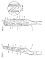
- a coolable turbine blade 10 for a gas turbine engine has an airfoil section 12 that extends radially across an engine flowpath 14.
- a peripheral wall 16 extends radially from the root 18 to the tip 22 of the airfoil 12 and chordwisely from a leading edge 24 to a trailing edge 26.
- the peripheral wall 16 has an external surface 28 that includes a concave or pressure surface 32 and a convex or suction surface 34 laterally spaced from the pressure surface.
- a mean camber line MCL extends chordwisely from the leading edge to the trailing edge midway between the pressure and suction surfaces.
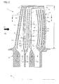
- the blade has a primary cooling system 42 comprising one or more radially extending medial passages 44, 46a, 46b, 46c and 48 bounded at least in part by the peripheral wall 16. Near the leading edge of the airfoil, feed passage 44 is in communication with impingement cavity 52 through a series of radially distributed impingement holes 54. An array of "showerhead” holes 56 extends from the impingement cavity to the airfoil surface 28 in the vicinity of the airfoil leading edge.
- Midchord medial passages 46a, 46b and 46c cool the midchord region of the airfoil.
- Passage 46a which is bifurcated by a radially extending rib 62, and chordwisely adjacent passage 46b are interconnected by an elbow 64 at their radially outermost extremities.
- Chordwisely adjacent passages 46b and 46c are similarly interconnected at their radially innermost extremities by elbow 66.
- each of the medial passages 46a, 46b and 46c is a leg of a serpentine passage 68.
- Judiciously oriented cooling holes 72 are distributed along the length of the serpentine, each hole extending from the serpentine to the airfoil external surface.
- An auxiliary cooling system 92 includes one or more radially continuous conduits, 94a - 94h (collectively designated 94), substantially parallel to and radially coextensive with the medial passages.
- Each conduit includes a series of radially spaced film cooling holes 96 and a series of exhaust vents 98.
- the conduits are disposed in the peripheral wall 16 laterally between the medial passages and the airfoil external surface 28, and are chordwisely situated within the zone of high heat load, i.e.
- Coolant C PS, C SS flows through the conduits thereby promoting more heat transfer from the peripheral wall than would be possible with the medial passages alone.
- a portion of the coolant discharges into the flowpath by way of the film cooling holes 96 to transpiration cool the airfoil and establish a thermally protective film along the external surface 28. Coolant that reaches the end of a conduit exhausts into the flowpath through exhaust vents 98.
- conduits 94 are substantially chordwisely coextensive with at least one of the medial passages so that coolant C PS and C SS absorbs heat from the peripheral wall 16 thereby thermally shielding or insulating the coolant in the chordwisely coextensive medial passages.
- conduits 94d - 94h along the pressure surface 32 are chordwisely coextensive with both the trailing edge feed passage 48 and with legs 46a and 46b of the serpentine passage 68. The chordwise coextensivity between the conduits and the trailing edge feed passage helps to reduce heat transfer into coolant C TE in the feed passage 48.
- conduits may be distributed over only a portion of either or both of the subzones.
- the extent to which the conduits of the auxiliary cooling system are present or absent is governed by a number of factors including the local intensity of the heat load and the desirability of mitigating the rise of coolant temperature in one or more of the medial passages.
- each auxiliary conduit 94 has a lateral dimension H and a chordwise dimension C and is bounded by a perimeter surface 108, a portion 112 of which is proximate to the external surface 28.
- the chordwise dimension exceeds the lateral dimension so that the cooling benefits of each individual conduit extend chordwisely as far as possible.
- the chordwise dimension is constrained, however, because each conduit divides the peripheral wall into a relatively cool inner portion 16a and a relatively hot outer portion 16b. If a conduit's chordwise dimension is too long, the temperature difference between the two wall portions 16a, 16b may cause thermally induced cracking of the airfoil.
- each conduit is limited to no more than about two and one half to three times the lateral distance D from the proximate perimeter surface 112 to the external surface 28.
- Adjacent conduits such as those in the illustrated embodiment, are separated by radially extending ribs 114 so that the inter-conduit distance I is at least about equal to lateral distance D.
- the inter-conduit ribs ensure sufficient heat transfer from wall portion 16a to wall portion 16b to attenuate the temperature difference and minimize the potential for cracking.
- An array of trip strips 116 extends laterally from the proximate surface 112 of each conduit. Because the conduit lateral dimension H is small relative to the lateral dimension of the medial passages, the conduit trip strips can be proportionately larger than the trip strips 116' employed in the medial passages without contributing inordinately to the weight of the airfoil.
- the lateral dimension or height H TS of the conduit trip strips exceeds 20% of the conduit lateral dimension H, and preferably is about 50% of the conduit lateral dimension.
- the trip strips are distributed so that the radial separation s ts (Fig. 4) between adjacent trip strips is between five and ten times the lateral dimension (e.g. H TS ) of the trip strips and preferably between five and seven times the lateral dimension. This trip strip density maximizes the heat transfer effectiveness of the trip strip array without imposing undue pressure loss on the stream of coolant.
- the replenishment passageways 122 are aligned with the interstices 124 distributed along the inter-conduit ribs 114 rather than with the conduits themselves. This alignment is advantageous since the replenishment coolant is expelled from the passageway as a high velocity jet of fluid. The fluid jet, if expelled directly into a conduit, could impede the radial flow of coolant through the conduit thereby interfering with effective heat transfer into the coolant.
- conduits are situated exclusively within the high heat load zone, rather than being distributed indiscriminately around the entire periphery of the airfoil, the benefit of the conduits can be concentrated wherever the demand for aggressive heat transfer is the greatest. Discriminate distribution of the conduits also facilitates selective shielding of coolant in the medial passages, thereby preserving the coolant's heat absorption capacity for use in other parts of the cooling circuit. Such sparing use of the conduits also helps minimize manufacturing costs since an airfoil having the small auxiliary conduits is more costly to manufacture than an airfoil having only the much larger medial passages. The small size of the conduits also permits the use of trip strips whose height, in proportion to the conduit lateral dimension, is sufficient to promote excellent heat transfer.
- the cooling conduits also ameliorate the problem of diminished coolant stream Reynold's Number due to the discharge of coolant along the length of a medial passage.
- suction surface conduits 94a, 94b, 94c allows the peripheral wall thickness t (Fig. 1) between leading edge feed passage 44 and airfoil suction surface 34 to be greater than the corresponding thickness in a prior art airfoil.
- the radial reduction in flow area A of the leading edge feed passage 44 is proportionally greater in the present airfoil than in a similar leading edge feed channel in a prior art airfoil.
- a similar compensatory effect could, if desired, be obtained adjacent to the midchord and trailing edge passages 46a, 46b, 46c and 48.
- the coolant in these passages is subjected to a lower heat load than the coolant in passage 44 and is adequately protected by the cooling film dispersed by film cooling holes 72.
- midchord medial passages are shown as being interconnected to form a serpentine, the invention also embraces an airfoil having independent or substantially independent midchord medial passages.
- individual designations have been assigned to the coolant supplied to the passages and conduits since each passage and conduit may each be supplied from its own dedicated source of coolant. In practice, however, a common coolant source may be used to supply more than one, or even all of the passages and conduits. A common coolant source for all the passages and conduits is, in fact, envisioned as the preferred embodiment.
- the invention provides a coolable airfoil for a turbine blade or vane that requires a minimum of coolant but is nevertheless capable of long duration service at high temperatures; a coolable airfoil whose heat transfer features are customized to the temperature distribution over the airfoil surface; a coolable airfoil that enjoys the heat absorption benefits of a serpentine cooling passage without experiencing excessive coolant temperature rise; a coolable airfoil whose coolant passages diminish in cross sectional area to maintain a high Reynolds Number in the coolant stream, but without inhibiting heat transfer due to increased distance between the perimeter of the passage and the airfoil surface; and a coolable airfoil having features that compensate for locally impaired heat transfer arising from rotational effects.
Landscapes
- Engineering & Computer Science (AREA)
- Mechanical Engineering (AREA)
- General Engineering & Computer Science (AREA)
- Turbine Rotor Nozzle Sealing (AREA)
Abstract
Description
Claims (14)
- A coolable airfoil (12), comprising:a peripheral wall (16) having an external surface (28) comprising a suction surface (34) and a pressure surface (32) laterally spaced from the suction surface (34), the surfaces extending chordwisely from a leading edge (24) to a trailing edge (26) and radially from an airfoil root (18) to an airfoil tip (22);a primary cooling system (42) comprising at least one radially extending medial passage (44, 46a, 46b, 46c, 48) bounded at least in part by the peripheral wall (16); andan auxiliary cooling system (92) comprising at least one cooling conduit (94) substantially parallel to and radially substantially coextensive with the medial passage, the conduit disposed in the wall between the medial passage and the external surface and chordwisely situated exclusively within a zone of high heat load (104, 106), the high heat load zone being from about 0% to 20% of the chordwise distance from the leading edge (24) to the trailing edge (26) along the suction surface (34) and about 10% to 75% of the chordwise distance from the leading edge (24) to the trailing edge (26) along the pressure surface (32).
- A coolable airfoil (12), comprising:a peripheral wall (16) having an external surface (28) comprising a suction surface (34) and a pressure surface (32) laterally spaced from the suction surface (34), the surfaces extending chordwisely from a leading edge (24) to a trailing edge (26) and radially from an airfoil root (18) to an airfoil tip (22);a primary cooling system (42) comprising chordwisely adjacent radially extending medial passages (42, 46a, 46b, 46c, 48), at least two of the medial passages (46a, 46b, 46c) being interconnected to form a cooling serpentine (68); andan auxiliary cooling system (92) comprising at least one cooling conduit (94) substantially parallel to and radially substantially coextensive with the medial passages, the conduit disposed in the wall between the medial passages and the external surface, the conduit (94) being chordwisely coextensive with at least one of the interconnected medial passages (46a, 46b, 46c) so that coolant flowing through the conduit (94) absorbs heat from the peripheral wall (16) thereby thermally insulating coolant flowing through the at least one medial passage (46a, 46b, 46c).
- A coolable airfoil (12), comprising:a peripheral wall (16) having an external surface (28) comprising a suction surface (34) and a pressure surface (32) laterally spaced from the suction surface (34), the surfaces extending chordwisely from a leading edge (24) to a trailing edge (26) and radially from an airfoil root (18) to an airfoil tip (22);a primary cooling system (42) comprising at least one radially extending medial passage (44, 46a, 46b, 46c, 48) bounded at least in part by the peripheral wall (16); andan auxiliary cooling system (92) comprising at least one cooling conduit (94) substantially parallel to and radially substantially coextensive with the medial passage, the conduit disposed in the wall between the medial passage and the external surface, the conduit having a chordwise dimension (C) and a lateral dimension (H), the chordwise dimension (C) being no more than about three times the distance from the conduit (94) to the external surface (28).
- A coolable airfoil as claimed in claim 1, wherein the primary cooling system comprises an array of chordwisely adjacent radially extending medial passages, at least two of the medial passages (46a, 46b, 46c) being interconnected to form a cooling serpentine (68), the conduit (94) being chordwisely coextensive with at least one of the interconnected medial passages (46a, 46b, 46c).
- A coolable airfoil as claimed in claim 1 or claim 4, wherein the conduit has a chordwise dimension (C) and a lateral dimension (H), the chordwise dimension (C) being no more than about three times the distance from the conduit (94) to the external surface (28).
- A coolable airfoil as claimed in claim 2, wherein the conduit has a chordwise dimension (C) and a lateral dimension (H), the chordwise dimension (C) being no more than about three times the distance from the conduit (94) to the external surface (28).
- A coolable airfoil as claimed in any of claims 1, 4 or 5, wherein cooling conduits (94) are chordwisely distributed over substantially the entire high heat load zone (104, 106).
- A coolable airfoil as claimed in any of claims 1, 4 or 5, wherein cooling conduits (94) are chordwisely distributed over substantially the entire high heat load zone (106) along the pressure surface (32) of the airfoil (12).
- A coolable airfoil as claimed in any of claims 1, 4 or 5, wherein cooling conduits (94) are chordwisely distributed over substantially the entire high heat load zone (104) along the suction surface (34) of the airfoil (12).
- A coolable airfoil as claimed in any preceding claim, wherein chordwisely adjacent cooling conduits (94) are separated by a radially extending rib (114) interrupted by one or more interstices (124).
- A coolable airfoil as claimed in claim 10 comprising one or more radially distributed replenishment passageways (122) extending from a medial passage to the auxiliary cooling system (92), the passageways (122) being aligned with the interstices (124).
- A coolable airfoil as claimed in any preceding claim, wherein each conduit has a lateral dimension (H) and a chordwise dimension (C) that exceeds the lateral dimension (H).
- A coolable airfoil as claimed in any preceding claim, wherein the conduits each have a lateral dimension (H) and a chordwise dimension (C) and are each bounded by a perimeter surface (108), a portion of the perimeter surface (112) being proximate the external surface (28), the proximate portion (112) having an array of trip strips (116) extending laterally therefrom, the trip strips (116) having a height (HTS) exceeds about 20% of the conduit lateral dimension (H) and preferably is about 50% of the conduit lateral dimension (H).
- A coolable airfoil as claimed in claim 13 wherein the trip strips (116) are spaced apart by a radial separation (sts) and the ratio of the radial separation (sts) to the trip strip height (HTS) is between about five and ten and preferably is between about five and seven.
Priority Applications (2)
| Application Number | Priority Date | Filing Date | Title |
|---|---|---|---|
| EP03029371A EP1420142B1 (en) | 1997-08-07 | 1998-08-07 | Cooled airfoil for turbine |
| EP03029372A EP1420143B1 (en) | 1997-08-07 | 1998-08-07 | Cooled airfoil for turbine |
Applications Claiming Priority (2)
| Application Number | Priority Date | Filing Date | Title |
|---|---|---|---|
| US08/908,403 US5931638A (en) | 1997-08-07 | 1997-08-07 | Turbomachinery airfoil with optimized heat transfer |
| US908403 | 1997-08-07 |
Related Child Applications (2)
| Application Number | Title | Priority Date | Filing Date |
|---|---|---|---|
| EP03029371A Division EP1420142B1 (en) | 1997-08-07 | 1998-08-07 | Cooled airfoil for turbine |
| EP03029372A Division EP1420143B1 (en) | 1997-08-07 | 1998-08-07 | Cooled airfoil for turbine |
Publications (3)
| Publication Number | Publication Date |
|---|---|
| EP0896127A2 true EP0896127A2 (en) | 1999-02-10 |
| EP0896127A3 EP0896127A3 (en) | 2000-05-24 |
| EP0896127B1 EP0896127B1 (en) | 2007-07-04 |
Family
ID=25425748
Family Applications (3)
| Application Number | Title | Priority Date | Filing Date |
|---|---|---|---|
| EP03029371A Expired - Lifetime EP1420142B1 (en) | 1997-08-07 | 1998-08-07 | Cooled airfoil for turbine |
| EP98306351A Expired - Lifetime EP0896127B1 (en) | 1997-08-07 | 1998-08-07 | Airfoil cooling |
| EP03029372A Expired - Lifetime EP1420143B1 (en) | 1997-08-07 | 1998-08-07 | Cooled airfoil for turbine |
Family Applications Before (1)
| Application Number | Title | Priority Date | Filing Date |
|---|---|---|---|
| EP03029371A Expired - Lifetime EP1420142B1 (en) | 1997-08-07 | 1998-08-07 | Cooled airfoil for turbine |
Family Applications After (1)
| Application Number | Title | Priority Date | Filing Date |
|---|---|---|---|
| EP03029372A Expired - Lifetime EP1420143B1 (en) | 1997-08-07 | 1998-08-07 | Cooled airfoil for turbine |
Country Status (4)
| Country | Link |
|---|---|
| US (1) | US5931638A (en) |
| EP (3) | EP1420142B1 (en) |
| JP (1) | JP4128662B2 (en) |
| DE (3) | DE69832116T2 (en) |
Cited By (35)
| Publication number | Priority date | Publication date | Assignee | Title |
|---|---|---|---|---|
| EP1001135A3 (en) * | 1998-11-16 | 2001-12-05 | General Electric Company | Airfoil with serial impingement cooling |
| GB2366600A (en) * | 2000-09-09 | 2002-03-13 | Rolls Royce Plc | Cooling arrangement for trailing edge of aerofoil |
| RU2188323C1 (en) * | 2001-02-21 | 2002-08-27 | "МАТИ" - Российский государственный технологический университет им. К.Э.Циолковского | Gas turbine cooled blade |
| EP1267039A1 (en) * | 2001-06-11 | 2002-12-18 | ALSTOM (Switzerland) Ltd | Cooling configuration for an airfoil trailing edge |
| GB2381298A (en) * | 2001-10-26 | 2003-04-30 | Rolls Royce Plc | A turbine blade having a greater thickness to chord ratio |
| RU2208683C1 (en) * | 2002-01-08 | 2003-07-20 | Ульяновский государственный технический университет | Cooled blade of turbine |
| EP1362982A1 (en) * | 2002-05-09 | 2003-11-19 | General Electric Company | Turbine airfoil with single aft flowing three pass serpentine cooling circuit |
| EP1091091A3 (en) * | 1999-10-05 | 2004-03-24 | United Technologies Corporation | Method and apparatus for cooling a wall within a gas turbine engine |
| EP1288437A3 (en) * | 2001-08-30 | 2004-06-09 | General Electric Company | Turbine airfoil for gas turbine engine |
| EP1605136A2 (en) | 2004-05-27 | 2005-12-14 | United Technologies Corporation | Cooled rotor blade |
| EP1607577A2 (en) | 2004-06-17 | 2005-12-21 | United Technologies Corporation | Turbine engine blades with drillable film cooling holes |
| RU2286464C2 (en) * | 2000-11-28 | 2006-10-27 | Нуово Пиньоне Холдинг С.П.А. | Cooling system of gas-turbine stator nozzles |
| EP1728970A2 (en) | 2005-05-31 | 2006-12-06 | United Technologies Corporation | Turbine blade cooling system |
| RU2297537C2 (en) * | 2001-12-10 | 2007-04-20 | Снекма Моторс | Rotor blade and high-pressure turbine of turbomachine |
| EP1600605A3 (en) * | 2004-05-27 | 2007-10-03 | United Technologies Corporation | Cooled rotor blade |
| EP1847684A1 (en) * | 2006-04-21 | 2007-10-24 | Siemens Aktiengesellschaft | Turbine blade |
| EP2078823A2 (en) | 2008-01-10 | 2009-07-15 | United Technologies Corporation | Cooling arrangement for turbine components |
| EP1640563A3 (en) * | 2004-09-20 | 2009-10-21 | United Technologies Corporation | Heat transfer augmentation in a compact heat exchanger pedestral array |
| EP1533480A3 (en) * | 2003-11-19 | 2009-10-28 | General Electric Company | Hot gas path component with mesh and turbulated cooling |
| EP1533475A3 (en) * | 2003-11-19 | 2009-11-04 | General Electric Company | Hot gas path component with mesh and dimpled cooling |
| EP1533481A3 (en) * | 2003-11-19 | 2009-11-04 | General Electric Company | Hot gas path component with a meshed and dimpled cooling structure |
| RU2374458C1 (en) * | 2008-03-28 | 2009-11-27 | Федеральное государственное унитарное предприятие "Московское машиностроительное производственное предприятие "САЛЮТ" (ФГУП "ММПП "САЛЮТ") | Gas turbine cooled blade |
| EP1801351A3 (en) * | 2005-12-22 | 2010-11-24 | United Technologies Corporation | Turbine blade tip cooling |
| WO2014055259A1 (en) * | 2012-10-04 | 2014-04-10 | General Electric Company | Air cooled turbine blade and corresponding method of cooling a turbine blade |
| WO2014137470A1 (en) * | 2013-03-05 | 2014-09-12 | Vandervaart Peter L | Gas turbine engine component arrangement |
| WO2015171145A1 (en) * | 2014-05-08 | 2015-11-12 | Siemens Energy, Inc. | Airfoil cooling with internal cavity displacement features |
| EP3044416A4 (en) * | 2013-09-09 | 2017-06-07 | United Technologies Corporation | Incidence tolerant engine component |
| EP3184742A1 (en) * | 2015-12-22 | 2017-06-28 | General Electric Company | Turbine airfoil with trailing edge cooling circuit |
| US9874110B2 (en) | 2013-03-07 | 2018-01-23 | Rolls-Royce North American Technologies Inc. | Cooled gas turbine engine component |
| EP3533971A1 (en) * | 2018-03-02 | 2019-09-04 | United Technologies Corporation | Airfoil with varying wall thickness |
| US10662781B2 (en) | 2012-12-28 | 2020-05-26 | Raytheon Technologies Corporation | Gas turbine engine component having vascular engineered lattice structure |
| EP3667023A1 (en) * | 2018-12-13 | 2020-06-17 | United Technologies Corporation | Airfoil with cooling passage network having flow guides |
| US10722735B2 (en) | 2005-11-18 | 2020-07-28 | Mevion Medical Systems, Inc. | Inner gantry |
| US10731473B2 (en) | 2012-12-28 | 2020-08-04 | Raytheon Technologies Corporation | Gas turbine engine component having engineered vascular structure |
| US10774653B2 (en) | 2018-12-11 | 2020-09-15 | Raytheon Technologies Corporation | Composite gas turbine engine component with lattice structure |
Families Citing this family (147)
| Publication number | Priority date | Publication date | Assignee | Title |
|---|---|---|---|---|
| DE19921644B4 (en) * | 1999-05-10 | 2012-01-05 | Alstom | Coolable blade for a gas turbine |
| US6190120B1 (en) * | 1999-05-14 | 2001-02-20 | General Electric Co. | Partially turbulated trailing edge cooling passages for gas turbine nozzles |
| JP3794868B2 (en) * | 1999-06-15 | 2006-07-12 | 三菱重工業株式会社 | Gas turbine stationary blade |
| US6179565B1 (en) * | 1999-08-09 | 2001-01-30 | United Technologies Corporation | Coolable airfoil structure |
| US6273682B1 (en) * | 1999-08-23 | 2001-08-14 | General Electric Company | Turbine blade with preferentially-cooled trailing edge pressure wall |
| US6283708B1 (en) * | 1999-12-03 | 2001-09-04 | United Technologies Corporation | Coolable vane or blade for a turbomachine |
| US6270317B1 (en) * | 1999-12-18 | 2001-08-07 | General Electric Company | Turbine nozzle with sloped film cooling |
| DE10001109B4 (en) * | 2000-01-13 | 2012-01-19 | Alstom Technology Ltd. | Cooled shovel for a gas turbine |
| US6325593B1 (en) * | 2000-02-18 | 2001-12-04 | General Electric Company | Ceramic turbine airfoils with cooled trailing edge blocks |
| EP1167689A1 (en) * | 2000-06-21 | 2002-01-02 | Siemens Aktiengesellschaft | Configuration of a coolable turbine blade |
| US6431832B1 (en) * | 2000-10-12 | 2002-08-13 | Solar Turbines Incorporated | Gas turbine engine airfoils with improved cooling |
| DE10064269A1 (en) * | 2000-12-22 | 2002-07-04 | Alstom Switzerland Ltd | Component of a turbomachine with an inspection opening |
| DE10064271A1 (en) * | 2000-12-22 | 2002-07-04 | Alstom Switzerland Ltd | Device for impingement cooling of a component which is exposed to heat in a turbo engine and method therefor |
| US6609891B2 (en) | 2001-08-30 | 2003-08-26 | General Electric Company | Turbine airfoil for gas turbine engine |
| WO2003054356A1 (en) * | 2001-12-10 | 2003-07-03 | Alstom Technology Ltd | Thermally loaded component |
| US7593030B2 (en) * | 2002-07-25 | 2009-09-22 | Intouch Technologies, Inc. | Tele-robotic videoconferencing in a corporate environment |
| US6918742B2 (en) * | 2002-09-05 | 2005-07-19 | Siemens Westinghouse Power Corporation | Combustion turbine with airfoil having multi-section diffusion cooling holes and methods of making same |
| US6805533B2 (en) | 2002-09-27 | 2004-10-19 | Siemens Westinghouse Power Corporation | Tolerant internally-cooled fluid guide component |
| US6808367B1 (en) * | 2003-06-09 | 2004-10-26 | Siemens Westinghouse Power Corporation | Cooling system for a turbine blade having a double outer wall |
| US6902372B2 (en) * | 2003-09-04 | 2005-06-07 | Siemens Westinghouse Power Corporation | Cooling system for a turbine blade |
| US6981840B2 (en) * | 2003-10-24 | 2006-01-03 | General Electric Company | Converging pin cooled airfoil |
| US6984103B2 (en) * | 2003-11-20 | 2006-01-10 | General Electric Company | Triple circuit turbine blade |
| US7021893B2 (en) * | 2004-01-09 | 2006-04-04 | United Technologies Corporation | Fanned trailing edge teardrop array |
| US7011502B2 (en) * | 2004-04-15 | 2006-03-14 | General Electric Company | Thermal shield turbine airfoil |
| US7665968B2 (en) * | 2004-05-27 | 2010-02-23 | United Technologies Corporation | Cooled rotor blade |
| US7186082B2 (en) * | 2004-05-27 | 2007-03-06 | United Technologies Corporation | Cooled rotor blade and method for cooling a rotor blade |
| US7118325B2 (en) * | 2004-06-14 | 2006-10-10 | United Technologies Corporation | Cooling passageway turn |
| US7195458B2 (en) * | 2004-07-02 | 2007-03-27 | Siemens Power Generation, Inc. | Impingement cooling system for a turbine blade |
| US7066716B2 (en) * | 2004-09-15 | 2006-06-27 | General Electric Company | Cooling system for the trailing edges of turbine bucket airfoils |
| EP1655451B1 (en) | 2004-11-09 | 2010-06-30 | Rolls-Royce Plc | A cooling arrangement |
| US7217095B2 (en) * | 2004-11-09 | 2007-05-15 | United Technologies Corporation | Heat transferring cooling features for an airfoil |
| US7478994B2 (en) * | 2004-11-23 | 2009-01-20 | United Technologies Corporation | Airfoil with supplemental cooling channel adjacent leading edge |
| US7150601B2 (en) * | 2004-12-23 | 2006-12-19 | United Technologies Corporation | Turbine airfoil cooling passageway |
| US7377746B2 (en) * | 2005-02-21 | 2008-05-27 | General Electric Company | Airfoil cooling circuits and method |
| US7413407B2 (en) * | 2005-03-29 | 2008-08-19 | Siemens Power Generation, Inc. | Turbine blade cooling system with bifurcated mid-chord cooling chamber |
| JP5039837B2 (en) * | 2005-03-30 | 2012-10-03 | 三菱重工業株式会社 | High temperature components for gas turbines |
| US7270515B2 (en) * | 2005-05-26 | 2007-09-18 | Siemens Power Generation, Inc. | Turbine airfoil trailing edge cooling system with segmented impingement ribs |
| US7296973B2 (en) * | 2005-12-05 | 2007-11-20 | General Electric Company | Parallel serpentine cooled blade |
| US7322795B2 (en) | 2006-01-27 | 2008-01-29 | United Technologies Corporation | Firm cooling method and hole manufacture |
| EP1881157B1 (en) * | 2006-07-18 | 2014-02-12 | United Technologies Corporation | Serpentine microcircuits for local heat removal |
| US7581928B1 (en) | 2006-07-28 | 2009-09-01 | United Technologies Corporation | Serpentine microcircuits for hot gas migration |
| US7481623B1 (en) | 2006-08-11 | 2009-01-27 | Florida Turbine Technologies, Inc. | Compartment cooled turbine blade |
| US7866948B1 (en) | 2006-08-16 | 2011-01-11 | Florida Turbine Technologies, Inc. | Turbine airfoil with near-wall impingement and vortex cooling |
| US7722324B2 (en) * | 2006-09-05 | 2010-05-25 | United Technologies Corporation | Multi-peripheral serpentine microcircuits for high aspect ratio blades |
| US7607891B2 (en) * | 2006-10-23 | 2009-10-27 | United Technologies Corporation | Turbine component with tip flagged pedestal cooling |
| US7556476B1 (en) | 2006-11-16 | 2009-07-07 | Florida Turbine Technologies, Inc. | Turbine airfoil with multiple near wall compartment cooling |
| US8413709B2 (en) * | 2006-12-06 | 2013-04-09 | General Electric Company | Composite core die, methods of manufacture thereof and articles manufactured therefrom |
| US7938168B2 (en) * | 2006-12-06 | 2011-05-10 | General Electric Company | Ceramic cores, methods of manufacture thereof and articles manufactured from the same |
| US7624787B2 (en) * | 2006-12-06 | 2009-12-01 | General Electric Company | Disposable insert, and use thereof in a method for manufacturing an airfoil |
| US20080135721A1 (en) * | 2006-12-06 | 2008-06-12 | General Electric Company | Casting compositions for manufacturing metal casting and methods of manufacturing thereof |
| US20100034647A1 (en) * | 2006-12-07 | 2010-02-11 | General Electric Company | Processes for the formation of positive features on shroud components, and related articles |
| US8884182B2 (en) | 2006-12-11 | 2014-11-11 | General Electric Company | Method of modifying the end wall contour in a turbine using laser consolidation and the turbines derived therefrom |
| US7487819B2 (en) * | 2006-12-11 | 2009-02-10 | General Electric Company | Disposable thin wall core die, methods of manufacture thereof and articles manufactured therefrom |
| US7780414B1 (en) * | 2007-01-17 | 2010-08-24 | Florida Turbine Technologies, Inc. | Turbine blade with multiple metering trailing edge cooling holes |
| US7819629B2 (en) * | 2007-02-15 | 2010-10-26 | Siemens Energy, Inc. | Blade for a gas turbine |
| US7780415B2 (en) * | 2007-02-15 | 2010-08-24 | Siemens Energy, Inc. | Turbine blade having a convergent cavity cooling system for a trailing edge |
| US7837441B2 (en) * | 2007-02-16 | 2010-11-23 | United Technologies Corporation | Impingement skin core cooling for gas turbine engine blade |
| US7775768B2 (en) * | 2007-03-06 | 2010-08-17 | United Technologies Corporation | Turbine component with axially spaced radially flowing microcircuit cooling channels |
| US7862299B1 (en) | 2007-03-21 | 2011-01-04 | Florida Turbine Technologies, Inc. | Two piece hollow turbine blade with serpentine cooling circuits |
| US7946815B2 (en) * | 2007-03-27 | 2011-05-24 | Siemens Energy, Inc. | Airfoil for a gas turbine engine |
| US7789625B2 (en) * | 2007-05-07 | 2010-09-07 | Siemens Energy, Inc. | Turbine airfoil with enhanced cooling |
| US8202054B2 (en) * | 2007-05-18 | 2012-06-19 | Siemens Energy, Inc. | Blade for a gas turbine engine |
| US7762775B1 (en) | 2007-05-31 | 2010-07-27 | Florida Turbine Technologies, Inc. | Turbine airfoil with cooled thin trailing edge |
| US7806659B1 (en) * | 2007-07-10 | 2010-10-05 | Florida Turbine Technologies, Inc. | Turbine blade with trailing edge bleed slot arrangement |
| US8257035B2 (en) * | 2007-12-05 | 2012-09-04 | Siemens Energy, Inc. | Turbine vane for a gas turbine engine |
| US8292581B2 (en) * | 2008-01-09 | 2012-10-23 | Honeywell International Inc. | Air cooled turbine blades and methods of manufacturing |
| EP2096261A1 (en) | 2008-02-28 | 2009-09-02 | Siemens Aktiengesellschaft | Turbine blade for a stationary gas turbine |
| US8172533B2 (en) * | 2008-05-14 | 2012-05-08 | United Technologies Corporation | Turbine blade internal cooling configuration |
| US8177507B2 (en) * | 2008-05-14 | 2012-05-15 | United Technologies Corporation | Triangular serpentine cooling channels |
| JP5717627B2 (en) * | 2008-06-12 | 2015-05-13 | アルストム テクノロジー リミテッドALSTOM Technology Ltd | Blades used in gas turbines and methods for producing such blades by casting technology |
| US8096770B2 (en) * | 2008-09-25 | 2012-01-17 | Siemens Energy, Inc. | Trailing edge cooling for turbine blade airfoil |
| US8096771B2 (en) * | 2008-09-25 | 2012-01-17 | Siemens Energy, Inc. | Trailing edge cooling slot configuration for a turbine airfoil |
| US8303252B2 (en) * | 2008-10-16 | 2012-11-06 | United Technologies Corporation | Airfoil with cooling passage providing variable heat transfer rate |
| US8137068B2 (en) * | 2008-11-21 | 2012-03-20 | United Technologies Corporation | Castings, casting cores, and methods |
| US8171978B2 (en) | 2008-11-21 | 2012-05-08 | United Technologies Corporation | Castings, casting cores, and methods |
| US8113780B2 (en) * | 2008-11-21 | 2012-02-14 | United Technologies Corporation | Castings, casting cores, and methods |
| US8109726B2 (en) * | 2009-01-19 | 2012-02-07 | Siemens Energy, Inc. | Turbine blade with micro channel cooling system |
| US8070443B1 (en) * | 2009-04-07 | 2011-12-06 | Florida Turbine Technologies, Inc. | Turbine blade with leading edge cooling |
| US8079821B2 (en) * | 2009-05-05 | 2011-12-20 | Siemens Energy, Inc. | Turbine airfoil with dual wall formed from inner and outer layers separated by a compliant structure |
| US8353669B2 (en) * | 2009-08-18 | 2013-01-15 | United Technologies Corporation | Turbine vane platform leading edge cooling holes |
| US8398370B1 (en) * | 2009-09-18 | 2013-03-19 | Florida Turbine Technologies, Inc. | Turbine blade with multi-impingement cooling |
| US8511994B2 (en) * | 2009-11-23 | 2013-08-20 | United Technologies Corporation | Serpentine cored airfoil with body microcircuits |
| US8535004B2 (en) * | 2010-03-26 | 2013-09-17 | Siemens Energy, Inc. | Four-wall turbine airfoil with thermal strain control for reduced cycle fatigue |
| US8894363B2 (en) | 2011-02-09 | 2014-11-25 | Siemens Energy, Inc. | Cooling module design and method for cooling components of a gas turbine system |
| US9334741B2 (en) * | 2010-04-22 | 2016-05-10 | Siemens Energy, Inc. | Discreetly defined porous wall structure for transpirational cooling |
| US8613597B1 (en) * | 2011-01-17 | 2013-12-24 | Florida Turbine Technologies, Inc. | Turbine blade with trailing edge cooling |
| US9011077B2 (en) | 2011-04-20 | 2015-04-21 | Siemens Energy, Inc. | Cooled airfoil in a turbine engine |
| US9033652B2 (en) | 2011-09-30 | 2015-05-19 | General Electric Company | Method and apparatus for cooling gas turbine rotor blades |
| US8858159B2 (en) | 2011-10-28 | 2014-10-14 | United Technologies Corporation | Gas turbine engine component having wavy cooling channels with pedestals |
| ITMI20120010A1 (en) * | 2012-01-05 | 2013-07-06 | Gen Electric | TURBINE AERODYNAMIC PROFILE IN SLIT |
| US9228437B1 (en) | 2012-03-22 | 2016-01-05 | Florida Turbine Technologies, Inc. | Turbine airfoil with pressure side trailing edge cooling slots |
| US9175569B2 (en) | 2012-03-30 | 2015-11-03 | General Electric Company | Turbine airfoil trailing edge cooling slots |
| US9017026B2 (en) | 2012-04-03 | 2015-04-28 | General Electric Company | Turbine airfoil trailing edge cooling slots |
| CA2870740C (en) | 2012-04-23 | 2017-06-13 | General Electric Company | Turbine airfoil with local wall thickness control |
| US9145773B2 (en) | 2012-05-09 | 2015-09-29 | General Electric Company | Asymmetrically shaped trailing edge cooling holes |
| DE102012212289A1 (en) * | 2012-07-13 | 2014-01-16 | Siemens Aktiengesellschaft | Turbine blade for a gas turbine |
| US10100646B2 (en) | 2012-08-03 | 2018-10-16 | United Technologies Corporation | Gas turbine engine component cooling circuit |
| US9157329B2 (en) * | 2012-08-22 | 2015-10-13 | United Technologies Corporation | Gas turbine engine airfoil internal cooling features |
| US9393620B2 (en) | 2012-12-14 | 2016-07-19 | United Technologies Corporation | Uber-cooled turbine section component made by additive manufacturing |
| US8920123B2 (en) | 2012-12-14 | 2014-12-30 | Siemens Aktiengesellschaft | Turbine blade with integrated serpentine and axial tip cooling circuits |
| US9850762B2 (en) | 2013-03-13 | 2017-12-26 | General Electric Company | Dust mitigation for turbine blade tip turns |
| US9638057B2 (en) | 2013-03-14 | 2017-05-02 | Rolls-Royce North American Technologies, Inc. | Augmented cooling system |
| EP2863010A1 (en) * | 2013-10-21 | 2015-04-22 | Siemens Aktiengesellschaft | Turbine blade |
| EP3060760B1 (en) | 2013-10-24 | 2018-12-05 | United Technologies Corporation | Airfoil with skin core cooling |
| US9039371B2 (en) | 2013-10-31 | 2015-05-26 | Siemens Aktiengesellschaft | Trailing edge cooling using angled impingement on surface enhanced with cast chevron arrangements |
| US10370981B2 (en) | 2014-02-13 | 2019-08-06 | United Technologies Corporation | Gas turbine engine component cooling circuit with respirating pedestal |
| EP2910887B1 (en) | 2014-02-21 | 2019-06-26 | Rolls-Royce Corporation | Microchannel heat exchangers for gas turbine intercooling and condensing as well as corresponding method |
| EP2910765B1 (en) * | 2014-02-21 | 2017-10-25 | Rolls-Royce Corporation | Single phase micro/mini channel heat exchangers for gas turbine intercooling and corresponding method |
| EP2937511B1 (en) | 2014-04-23 | 2022-06-01 | Raytheon Technologies Corporation | Gas turbine engine airfoil cooling passage configuration |
| FR3021697B1 (en) * | 2014-05-28 | 2021-09-17 | Snecma | OPTIMIZED COOLING TURBINE BLADE |
| US20170074116A1 (en) * | 2014-07-17 | 2017-03-16 | United Technologies Corporation | Method of creating heat transfer features in high temperature alloys |
| US10316751B2 (en) | 2014-08-28 | 2019-06-11 | United Technologies Corporation | Shielded pass through passage in a gas turbine engine structure |
| US10094287B2 (en) | 2015-02-10 | 2018-10-09 | United Technologies Corporation | Gas turbine engine component with vascular cooling scheme |
| CN107429569B (en) | 2015-04-03 | 2019-09-24 | 西门子公司 | Turbine bucket trailing edge with low flow framed channels |
| US10443398B2 (en) | 2015-10-15 | 2019-10-15 | General Electric Company | Turbine blade |
| US10208605B2 (en) * | 2015-10-15 | 2019-02-19 | General Electric Company | Turbine blade |
| US10370978B2 (en) | 2015-10-15 | 2019-08-06 | General Electric Company | Turbine blade |
| US10174620B2 (en) | 2015-10-15 | 2019-01-08 | General Electric Company | Turbine blade |
| JP6671149B2 (en) * | 2015-11-05 | 2020-03-25 | 三菱日立パワーシステムズ株式会社 | Turbine blade and gas turbine, intermediate product of turbine blade, and method of manufacturing turbine blade |
| US10563518B2 (en) * | 2016-02-15 | 2020-02-18 | General Electric Company | Gas turbine engine trailing edge ejection holes |
| US10221694B2 (en) | 2016-02-17 | 2019-03-05 | United Technologies Corporation | Gas turbine engine component having vascular engineered lattice structure |
| US10337332B2 (en) * | 2016-02-25 | 2019-07-02 | United Technologies Corporation | Airfoil having pedestals in trailing edge cavity |
| FR3048718B1 (en) * | 2016-03-10 | 2020-01-24 | Safran | OPTIMIZED COOLING TURBOMACHINE BLADE |
| US10508552B2 (en) | 2016-04-11 | 2019-12-17 | United Technologies Corporation | Internally cooled airfoil |
| US10208604B2 (en) | 2016-04-27 | 2019-02-19 | United Technologies Corporation | Cooling features with three dimensional chevron geometry |
| FR3056631B1 (en) * | 2016-09-29 | 2018-10-19 | Safran | IMPROVED COOLING CIRCUIT FOR AUBES |
| US10450950B2 (en) * | 2016-10-26 | 2019-10-22 | General Electric Company | Turbomachine blade with trailing edge cooling circuit |
| US10697301B2 (en) | 2017-04-07 | 2020-06-30 | General Electric Company | Turbine engine airfoil having a cooling circuit |
| US10767490B2 (en) * | 2017-09-08 | 2020-09-08 | Raytheon Technologies Corporation | Hot section engine components having segment gap discharge holes |
| US10526898B2 (en) * | 2017-10-24 | 2020-01-07 | United Technologies Corporation | Airfoil cooling circuit |
| US10989067B2 (en) | 2018-07-13 | 2021-04-27 | Honeywell International Inc. | Turbine vane with dust tolerant cooling system |
| US10787932B2 (en) | 2018-07-13 | 2020-09-29 | Honeywell International Inc. | Turbine blade with dust tolerant cooling system |
| US10669862B2 (en) | 2018-07-13 | 2020-06-02 | Honeywell International Inc. | Airfoil with leading edge convective cooling system |
| US11073023B2 (en) * | 2018-08-21 | 2021-07-27 | Raytheon Technologies Corporation | Airfoil having improved throughflow cooling scheme and damage resistance |
| US11377964B2 (en) * | 2018-11-09 | 2022-07-05 | Raytheon Technologies Corporation | Airfoil with cooling passage network having arced leading edge |
| US11499433B2 (en) | 2018-12-18 | 2022-11-15 | General Electric Company | Turbine engine component and method of cooling |
| US11566527B2 (en) | 2018-12-18 | 2023-01-31 | General Electric Company | Turbine engine airfoil and method of cooling |
| US11352889B2 (en) | 2018-12-18 | 2022-06-07 | General Electric Company | Airfoil tip rail and method of cooling |
| US10767492B2 (en) | 2018-12-18 | 2020-09-08 | General Electric Company | Turbine engine airfoil |
| US11174736B2 (en) | 2018-12-18 | 2021-11-16 | General Electric Company | Method of forming an additively manufactured component |
| JP7206129B2 (en) * | 2019-02-26 | 2023-01-17 | 三菱重工業株式会社 | wings and machines equipped with them |
| US10844728B2 (en) | 2019-04-17 | 2020-11-24 | General Electric Company | Turbine engine airfoil with a trailing edge |
| US11230929B2 (en) | 2019-11-05 | 2022-01-25 | Honeywell International Inc. | Turbine component with dust tolerant cooling system |
| US11952911B2 (en) * | 2019-11-14 | 2024-04-09 | Rtx Corporation | Airfoil with connecting rib |
| US11203947B2 (en) | 2020-05-08 | 2021-12-21 | Raytheon Technologies Corporation | Airfoil having internally cooled wall with liner and shell |
| US11814965B2 (en) | 2021-11-10 | 2023-11-14 | General Electric Company | Turbomachine blade trailing edge cooling circuit with turn passage having set of obstructions |
| KR102953259B1 (en) * | 2023-12-26 | 2026-04-17 | 두산에너빌리티 주식회사 | Airfoil and gas turbine comprising it |
Family Cites Families (22)
| Publication number | Priority date | Publication date | Assignee | Title |
|---|---|---|---|---|
| US3240468A (en) * | 1964-12-28 | 1966-03-15 | Curtiss Wright Corp | Transpiration cooled blades for turbines, compressors, and the like |
| US3810711A (en) * | 1972-09-22 | 1974-05-14 | Gen Motors Corp | Cooled turbine blade and its manufacture |
| US4025226A (en) * | 1975-10-03 | 1977-05-24 | United Technologies Corporation | Air cooled turbine vane |
| US4118146A (en) * | 1976-08-11 | 1978-10-03 | United Technologies Corporation | Coolable wall |
| US4775296A (en) * | 1981-12-28 | 1988-10-04 | United Technologies Corporation | Coolable airfoil for a rotary machine |
| US4627480A (en) * | 1983-11-07 | 1986-12-09 | General Electric Company | Angled turbulence promoter |
| US4770608A (en) * | 1985-12-23 | 1988-09-13 | United Technologies Corporation | Film cooled vanes and turbines |
| US4767268A (en) * | 1987-08-06 | 1988-08-30 | United Technologies Corporation | Triple pass cooled airfoil |
| US5720431A (en) * | 1988-08-24 | 1998-02-24 | United Technologies Corporation | Cooled blades for a gas turbine engine |
| US5405242A (en) * | 1990-07-09 | 1995-04-11 | United Technologies Corporation | Cooled vane |
| FR2678318B1 (en) * | 1991-06-25 | 1993-09-10 | Snecma | COOLED VANE OF TURBINE DISTRIBUTOR. |
| US5356265A (en) * | 1992-08-25 | 1994-10-18 | General Electric Company | Chordally bifurcated turbine blade |
| US5403159A (en) * | 1992-11-30 | 1995-04-04 | United Technoligies Corporation | Coolable airfoil structure |
| US5328331A (en) * | 1993-06-28 | 1994-07-12 | General Electric Company | Turbine airfoil with double shell outer wall |
| US5472316A (en) * | 1994-09-19 | 1995-12-05 | General Electric Company | Enhanced cooling apparatus for gas turbine engine airfoils |
| US5702232A (en) * | 1994-12-13 | 1997-12-30 | United Technologies Corporation | Cooled airfoils for a gas turbine engine |
| US5626462A (en) * | 1995-01-03 | 1997-05-06 | General Electric Company | Double-wall airfoil |
| US5669759A (en) * | 1995-02-03 | 1997-09-23 | United Technologies Corporation | Turbine airfoil with enhanced cooling |
| US5498133A (en) * | 1995-06-06 | 1996-03-12 | General Electric Company | Pressure regulated film cooling |
| US5813836A (en) * | 1996-12-24 | 1998-09-29 | General Electric Company | Turbine blade |
| EP0964981B1 (en) * | 1997-02-20 | 2002-12-04 | Siemens Aktiengesellschaft | Turbine blade and its use in a gas turbine system |
| JP4170400B2 (en) * | 1997-04-07 | 2008-10-22 | シーメンス アクチエンゲゼルシヤフト | Turbine blade, its use and cooling method of turbine blade |
-
1997
- 1997-08-07 US US08/908,403 patent/US5931638A/en not_active Expired - Lifetime
-
1998
- 1998-08-07 DE DE69832116T patent/DE69832116T2/en not_active Expired - Lifetime
- 1998-08-07 DE DE69838015T patent/DE69838015T2/en not_active Expired - Lifetime
- 1998-08-07 EP EP03029371A patent/EP1420142B1/en not_active Expired - Lifetime
- 1998-08-07 JP JP22391698A patent/JP4128662B2/en not_active Expired - Fee Related
- 1998-08-07 EP EP98306351A patent/EP0896127B1/en not_active Expired - Lifetime
- 1998-08-07 DE DE69836156T patent/DE69836156T2/en not_active Expired - Lifetime
- 1998-08-07 EP EP03029372A patent/EP1420143B1/en not_active Expired - Lifetime
Cited By (54)
| Publication number | Priority date | Publication date | Assignee | Title |
|---|---|---|---|---|
| EP1001135A3 (en) * | 1998-11-16 | 2001-12-05 | General Electric Company | Airfoil with serial impingement cooling |
| EP1617043A1 (en) * | 1999-10-05 | 2006-01-18 | United Technologies Corporation | Method for cooling a wall within a gas turbine engine |
| EP1091091A3 (en) * | 1999-10-05 | 2004-03-24 | United Technologies Corporation | Method and apparatus for cooling a wall within a gas turbine engine |
| GB2366600A (en) * | 2000-09-09 | 2002-03-13 | Rolls Royce Plc | Cooling arrangement for trailing edge of aerofoil |
| RU2286464C2 (en) * | 2000-11-28 | 2006-10-27 | Нуово Пиньоне Холдинг С.П.А. | Cooling system of gas-turbine stator nozzles |
| RU2188323C1 (en) * | 2001-02-21 | 2002-08-27 | "МАТИ" - Российский государственный технологический университет им. К.Э.Циолковского | Gas turbine cooled blade |
| US6616406B2 (en) | 2001-06-11 | 2003-09-09 | Alstom (Switzerland) Ltd | Airfoil trailing edge cooling construction |
| EP1267039A1 (en) * | 2001-06-11 | 2002-12-18 | ALSTOM (Switzerland) Ltd | Cooling configuration for an airfoil trailing edge |
| CH695788A5 (en) * | 2001-06-11 | 2006-08-31 | Alstom Technology Ltd | Airfoil for a gas turbine having a cooling structure for its airfoil trailing edge. |
| EP1288437A3 (en) * | 2001-08-30 | 2004-06-09 | General Electric Company | Turbine airfoil for gas turbine engine |
| GB2381298A (en) * | 2001-10-26 | 2003-04-30 | Rolls Royce Plc | A turbine blade having a greater thickness to chord ratio |
| RU2297537C2 (en) * | 2001-12-10 | 2007-04-20 | Снекма Моторс | Rotor blade and high-pressure turbine of turbomachine |
| RU2208683C1 (en) * | 2002-01-08 | 2003-07-20 | Ульяновский государственный технический университет | Cooled blade of turbine |
| EP1362982A1 (en) * | 2002-05-09 | 2003-11-19 | General Electric Company | Turbine airfoil with single aft flowing three pass serpentine cooling circuit |
| EP1533481A3 (en) * | 2003-11-19 | 2009-11-04 | General Electric Company | Hot gas path component with a meshed and dimpled cooling structure |
| EP1533480A3 (en) * | 2003-11-19 | 2009-10-28 | General Electric Company | Hot gas path component with mesh and turbulated cooling |
| EP1533475A3 (en) * | 2003-11-19 | 2009-11-04 | General Electric Company | Hot gas path component with mesh and dimpled cooling |
| EP1600605A3 (en) * | 2004-05-27 | 2007-10-03 | United Technologies Corporation | Cooled rotor blade |
| EP1605136A2 (en) | 2004-05-27 | 2005-12-14 | United Technologies Corporation | Cooled rotor blade |
| EP1605136A3 (en) * | 2004-05-27 | 2009-01-21 | United Technologies Corporation | Cooled rotor blade |
| EP1607577A2 (en) | 2004-06-17 | 2005-12-21 | United Technologies Corporation | Turbine engine blades with drillable film cooling holes |
| EP1607577A3 (en) * | 2004-06-17 | 2009-07-22 | United Technologies Corporation | Turbine engine blades with drillable film cooling holes |
| US7775053B2 (en) | 2004-09-20 | 2010-08-17 | United Technologies Corporation | Heat transfer augmentation in a compact heat exchanger pedestal array |
| EP1640563A3 (en) * | 2004-09-20 | 2009-10-21 | United Technologies Corporation | Heat transfer augmentation in a compact heat exchanger pedestral array |
| EP1728970A2 (en) | 2005-05-31 | 2006-12-06 | United Technologies Corporation | Turbine blade cooling system |
| EP1728970A3 (en) * | 2005-05-31 | 2009-12-09 | United Technologies Corporation | Turbine blade cooling system |
| US10722735B2 (en) | 2005-11-18 | 2020-07-28 | Mevion Medical Systems, Inc. | Inner gantry |
| EP1801351A3 (en) * | 2005-12-22 | 2010-11-24 | United Technologies Corporation | Turbine blade tip cooling |
| WO2007122022A1 (en) * | 2006-04-21 | 2007-11-01 | Siemens Aktiengesellschaft | Turbine blade |
| US8092175B2 (en) | 2006-04-21 | 2012-01-10 | Siemens Aktiengesellschaft | Turbine blade |
| EP1847684A1 (en) * | 2006-04-21 | 2007-10-24 | Siemens Aktiengesellschaft | Turbine blade |
| RU2399771C2 (en) * | 2006-04-21 | 2010-09-20 | Сименс Акциенгезелльшафт | Turbine blade |
| EP2078823A3 (en) * | 2008-01-10 | 2012-11-07 | United Technologies Corporation | Cooling arrangement for turbine components |
| EP2078823A2 (en) | 2008-01-10 | 2009-07-15 | United Technologies Corporation | Cooling arrangement for turbine components |
| RU2374458C1 (en) * | 2008-03-28 | 2009-11-27 | Федеральное государственное унитарное предприятие "Московское машиностроительное производственное предприятие "САЛЮТ" (ФГУП "ММПП "САЛЮТ") | Gas turbine cooled blade |
| WO2014055259A1 (en) * | 2012-10-04 | 2014-04-10 | General Electric Company | Air cooled turbine blade and corresponding method of cooling a turbine blade |
| US9995148B2 (en) | 2012-10-04 | 2018-06-12 | General Electric Company | Method and apparatus for cooling gas turbine and rotor blades |
| US10662781B2 (en) | 2012-12-28 | 2020-05-26 | Raytheon Technologies Corporation | Gas turbine engine component having vascular engineered lattice structure |
| US10731473B2 (en) | 2012-12-28 | 2020-08-04 | Raytheon Technologies Corporation | Gas turbine engine component having engineered vascular structure |
| WO2014137470A1 (en) * | 2013-03-05 | 2014-09-12 | Vandervaart Peter L | Gas turbine engine component arrangement |
| US9879601B2 (en) | 2013-03-05 | 2018-01-30 | Rolls-Royce North American Technologies Inc. | Gas turbine engine component arrangement |
| US9874110B2 (en) | 2013-03-07 | 2018-01-23 | Rolls-Royce North American Technologies Inc. | Cooled gas turbine engine component |
| EP3044416A4 (en) * | 2013-09-09 | 2017-06-07 | United Technologies Corporation | Incidence tolerant engine component |
| WO2015171145A1 (en) * | 2014-05-08 | 2015-11-12 | Siemens Energy, Inc. | Airfoil cooling with internal cavity displacement features |
| US10428686B2 (en) | 2014-05-08 | 2019-10-01 | Siemens Energy, Inc. | Airfoil cooling with internal cavity displacement features |
| EP3184742A1 (en) * | 2015-12-22 | 2017-06-28 | General Electric Company | Turbine airfoil with trailing edge cooling circuit |
| US9909427B2 (en) | 2015-12-22 | 2018-03-06 | General Electric Company | Turbine airfoil with trailing edge cooling circuit |
| EP3533971A1 (en) * | 2018-03-02 | 2019-09-04 | United Technologies Corporation | Airfoil with varying wall thickness |
| US10731474B2 (en) | 2018-03-02 | 2020-08-04 | Raytheon Technologies Corporation | Airfoil with varying wall thickness |
| US10774653B2 (en) | 2018-12-11 | 2020-09-15 | Raytheon Technologies Corporation | Composite gas turbine engine component with lattice structure |
| US11168568B2 (en) | 2018-12-11 | 2021-11-09 | Raytheon Technologies Corporation | Composite gas turbine engine component with lattice |
| EP3667023A1 (en) * | 2018-12-13 | 2020-06-17 | United Technologies Corporation | Airfoil with cooling passage network having flow guides |
| US11028702B2 (en) | 2018-12-13 | 2021-06-08 | Raytheon Technologies Corporation | Airfoil with cooling passage network having flow guides |
| EP4471256A3 (en) * | 2018-12-13 | 2025-03-05 | RTX Corporation | Airfoil with cooling passages network having flow guides |
Also Published As
| Publication number | Publication date |
|---|---|
| US5931638A (en) | 1999-08-03 |
| DE69832116T2 (en) | 2006-04-20 |
| EP1420142B1 (en) | 2005-10-26 |
| DE69832116D1 (en) | 2005-12-01 |
| DE69836156T2 (en) | 2007-02-01 |
| EP1420143A1 (en) | 2004-05-19 |
| EP0896127A3 (en) | 2000-05-24 |
| JP4128662B2 (en) | 2008-07-30 |
| JPH11107702A (en) | 1999-04-20 |
| DE69838015T2 (en) | 2008-03-13 |
| EP0896127B1 (en) | 2007-07-04 |
| EP1420143B1 (en) | 2006-10-11 |
| DE69836156D1 (en) | 2006-11-23 |
| EP1420142A1 (en) | 2004-05-19 |
| DE69838015D1 (en) | 2007-08-16 |
Similar Documents
| Publication | Publication Date | Title |
|---|---|---|
| EP0896127B1 (en) | Airfoil cooling | |
| US10669896B2 (en) | Dirt separator for internally cooled components | |
| US7442008B2 (en) | Cooled gas turbine aerofoil | |
| US5813836A (en) | Turbine blade | |
| US6955522B2 (en) | Method and apparatus for cooling an airfoil | |
| US8096767B1 (en) | Turbine blade with serpentine cooling circuit formed within the tip shroud | |
| US5902093A (en) | Crack arresting rotor blade | |
| US6607355B2 (en) | Turbine airfoil with enhanced heat transfer | |
| EP1469164B1 (en) | Complementary cooled turbine nozzle | |
| US7901183B1 (en) | Turbine blade with dual aft flowing triple pass serpentines | |
| US6283708B1 (en) | Coolable vane or blade for a turbomachine | |
| US9151173B2 (en) | Use of multi-faceted impingement openings for increasing heat transfer characteristics on gas turbine components | |
| US7527475B1 (en) | Turbine blade with a near-wall cooling circuit | |
| US7967566B2 (en) | Thermally balanced near wall cooling for a turbine blade | |
| EP2860359B1 (en) | Arrangement for cooling a component in the hot gas path of a gas turbine | |
| US8585365B1 (en) | Turbine blade with triple pass serpentine cooling | |
| JP4527848B2 (en) | Airfoil with insulated tip | |
| EP0852284A1 (en) | Turbulator configuration for cooling passages of an airfoil in a gas turbine engine | |
| JP2010261460A (en) | Turbine nozzle with sidewall cooling plenum | |
| JP5090686B2 (en) | Cooled turbine shroud | |
| JP2008025567A (en) | Turbine engine component having airfoil portion having pressure side and suction side | |
| US6224329B1 (en) | Method of cooling a combustion turbine | |
| EP3196423B1 (en) | Stator heat shield for a gas turbine and corresponding gas turbine | |
| JP2015132266A (en) | Cooled stator heat shield | |
| JP4057573B2 (en) | Turbine engine parts |
Legal Events
| Date | Code | Title | Description |
|---|---|---|---|
| PUAI | Public reference made under article 153(3) epc to a published international application that has entered the european phase |
Free format text: ORIGINAL CODE: 0009012 |
|
| AK | Designated contracting states |
Kind code of ref document: A2 Designated state(s): DE FR GB |
|
| AX | Request for extension of the european patent |
Free format text: AL;LT;LV;MK;RO;SI |
|
| PUAL | Search report despatched |
Free format text: ORIGINAL CODE: 0009013 |
|
| AK | Designated contracting states |
Kind code of ref document: A3 Designated state(s): AT BE CH CY DE DK ES FI FR GB GR IE IT LI LU MC NL PT SE |
|
| AX | Request for extension of the european patent |
Free format text: AL;LT;LV;MK;RO;SI |
|
| 17P | Request for examination filed |
Effective date: 20000628 |
|
| AKX | Designation fees paid |
Free format text: DE FR GB |
|
| 17Q | First examination report despatched |
Effective date: 20030612 |
|
| GRAP | Despatch of communication of intention to grant a patent |
Free format text: ORIGINAL CODE: EPIDOSNIGR1 |
|
| GRAS | Grant fee paid |
Free format text: ORIGINAL CODE: EPIDOSNIGR3 |
|
| GRAA | (expected) grant |
Free format text: ORIGINAL CODE: 0009210 |
|
| AK | Designated contracting states |
Kind code of ref document: B1 Designated state(s): DE FR GB |
|
| REG | Reference to a national code |
Ref country code: GB Ref legal event code: FG4D |
|
| REF | Corresponds to: |
Ref document number: 69838015 Country of ref document: DE Date of ref document: 20070816 Kind code of ref document: P |
|
| ET | Fr: translation filed | ||
| PLBE | No opposition filed within time limit |
Free format text: ORIGINAL CODE: 0009261 |
|
| STAA | Information on the status of an ep patent application or granted ep patent |
Free format text: STATUS: NO OPPOSITION FILED WITHIN TIME LIMIT |
|
| 26N | No opposition filed |
Effective date: 20080407 |
|
| REG | Reference to a national code |
Ref country code: FR Ref legal event code: ST Effective date: 20080630 |
|
| PG25 | Lapsed in a contracting state [announced via postgrant information from national office to epo] |
Ref country code: FR Free format text: LAPSE BECAUSE OF NON-PAYMENT OF DUE FEES Effective date: 20070831 |
|
| PGFP | Annual fee paid to national office [announced via postgrant information from national office to epo] |
Ref country code: GB Payment date: 20090728 Year of fee payment: 12 |
|
| GBPC | Gb: european patent ceased through non-payment of renewal fee |
Effective date: 20100807 |
|
| PG25 | Lapsed in a contracting state [announced via postgrant information from national office to epo] |
Ref country code: GB Free format text: LAPSE BECAUSE OF NON-PAYMENT OF DUE FEES Effective date: 20100807 |
|
| PGFP | Annual fee paid to national office [announced via postgrant information from national office to epo] |
Ref country code: DE Payment date: 20150722 Year of fee payment: 18 |
|
| REG | Reference to a national code |
Ref country code: DE Ref legal event code: R119 Ref document number: 69838015 Country of ref document: DE |
|
| PG25 | Lapsed in a contracting state [announced via postgrant information from national office to epo] |
Ref country code: DE Free format text: LAPSE BECAUSE OF NON-PAYMENT OF DUE FEES Effective date: 20170301 |