RU2286464C2 - Cooling system of gas-turbine stator nozzles - Google Patents
Cooling system of gas-turbine stator nozzles Download PDFInfo
- Publication number
- RU2286464C2 RU2286464C2 RU2001132142/06A RU2001132142A RU2286464C2 RU 2286464 C2 RU2286464 C2 RU 2286464C2 RU 2001132142/06 A RU2001132142/06 A RU 2001132142/06A RU 2001132142 A RU2001132142 A RU 2001132142A RU 2286464 C2 RU2286464 C2 RU 2286464C2
- Authority
- RU
- Russia
- Prior art keywords
- blade
- cooling
- concave surface
- blades
- cooling system
- Prior art date
Links
Images
Classifications
-
- F—MECHANICAL ENGINEERING; LIGHTING; HEATING; WEAPONS; BLASTING
- F01—MACHINES OR ENGINES IN GENERAL; ENGINE PLANTS IN GENERAL; STEAM ENGINES
- F01D—NON-POSITIVE DISPLACEMENT MACHINES OR ENGINES, e.g. STEAM TURBINES
- F01D5/00—Blades; Blade-carrying members; Heating, heat-insulating, cooling or antivibration means on the blades or the members
- F01D5/12—Blades
- F01D5/14—Form or construction
- F01D5/18—Hollow blades, i.e. blades with cooling or heating channels or cavities; Heating, heat-insulating or cooling means on blades
- F01D5/186—Film cooling
-
- F—MECHANICAL ENGINEERING; LIGHTING; HEATING; WEAPONS; BLASTING
- F01—MACHINES OR ENGINES IN GENERAL; ENGINE PLANTS IN GENERAL; STEAM ENGINES
- F01D—NON-POSITIVE DISPLACEMENT MACHINES OR ENGINES, e.g. STEAM TURBINES
- F01D5/00—Blades; Blade-carrying members; Heating, heat-insulating, cooling or antivibration means on the blades or the members
- F01D5/12—Blades
- F01D5/14—Form or construction
- F01D5/18—Hollow blades, i.e. blades with cooling or heating channels or cavities; Heating, heat-insulating or cooling means on blades
- F01D5/187—Convection cooling
-
- F—MECHANICAL ENGINEERING; LIGHTING; HEATING; WEAPONS; BLASTING
- F05—INDEXING SCHEMES RELATING TO ENGINES OR PUMPS IN VARIOUS SUBCLASSES OF CLASSES F01-F04
- F05D—INDEXING SCHEME FOR ASPECTS RELATING TO NON-POSITIVE-DISPLACEMENT MACHINES OR ENGINES, GAS-TURBINES OR JET-PROPULSION PLANTS
- F05D2240/00—Components
- F05D2240/10—Stators
- F05D2240/12—Fluid guiding means, e.g. vanes
-
- F—MECHANICAL ENGINEERING; LIGHTING; HEATING; WEAPONS; BLASTING
- F05—INDEXING SCHEMES RELATING TO ENGINES OR PUMPS IN VARIOUS SUBCLASSES OF CLASSES F01-F04
- F05D—INDEXING SCHEME FOR ASPECTS RELATING TO NON-POSITIVE-DISPLACEMENT MACHINES OR ENGINES, GAS-TURBINES OR JET-PROPULSION PLANTS
- F05D2250/00—Geometry
- F05D2250/30—Arrangement of components
- F05D2250/32—Arrangement of components according to their shape
- F05D2250/323—Arrangement of components according to their shape convergent
-
- F—MECHANICAL ENGINEERING; LIGHTING; HEATING; WEAPONS; BLASTING
- F05—INDEXING SCHEMES RELATING TO ENGINES OR PUMPS IN VARIOUS SUBCLASSES OF CLASSES F01-F04
- F05D—INDEXING SCHEME FOR ASPECTS RELATING TO NON-POSITIVE-DISPLACEMENT MACHINES OR ENGINES, GAS-TURBINES OR JET-PROPULSION PLANTS
- F05D2260/00—Function
- F05D2260/20—Heat transfer, e.g. cooling
- F05D2260/202—Heat transfer, e.g. cooling by film cooling
Abstract
Description
Настоящее изобретение относится к системе охлаждения для сопел статора газовых турбин.The present invention relates to a cooling system for gas turbine stator nozzles.
Как известно, газовые турбины представляют собой машины, которые состоят из компрессора и турбины с одной или более ступенями, при этом упомянутые компоненты соединены друг с другом посредством вращательного вала, а между компрессором и турбиной размещена камера сгорания.As is known, gas turbines are machines that consist of a compressor and a turbine with one or more stages, the above-mentioned components being connected to each other by means of a rotational shaft, and a combustion chamber is placed between the compressor and the turbine.
В этих машинах воздух, забираемый из внешней среды, поступает к компрессору, с тем чтобы последний обеспечивал повышенное давление воздуха.In these machines, air drawn from the external environment enters the compressor so that the latter provides increased air pressure.
Сжатый воздух проходит через ряд камер предварительного перемешивания, каждая из которых заканчивается сходящейся частью, в каждую из которых инжектор подает топливо, которое перемешивается с воздухом для формирования воздушно-топливной смеси, предназначенной для ее сжигания.Compressed air passes through a series of pre-mixing chambers, each of which ends with a converging part, into each of which an injector delivers fuel, which is mixed with air to form an air-fuel mixture intended for its combustion.
Внутрь камеры сгорания подводится топливо, которое воспламеняется посредством соответствующих свечей зажигания, чтобы вызвать горение, которое предназначено для того, чтобы повысить температуру и давление, и, следовательно, энтальпию газа.Inside the combustion chamber, fuel is supplied, which is ignited by the respective spark plugs, to cause combustion, which is intended to increase temperature and pressure, and therefore the enthalpy of the gas.
Одновременно компрессор подает сжатый воздух, который должен проходить как через горелки, так и жаровые трубы камеры сгорания, чтобы обеспечивался доступ сжатого воздуха для поддерживания горения.At the same time, the compressor delivers compressed air, which must pass both through the burners and the flame tubes of the combustion chamber, in order to ensure access of compressed air to maintain combustion.
После этого газ, имеющий высокую температуру и находящийся под высоким давлением, по соответствующим трубам доходит до разных ступеней турбины, преобразующей энтальпию газа в механическую энергию, которая может быть использована потребителем.After that, gas having a high temperature and under high pressure reaches the various stages of the turbine through the corresponding pipes, converting the enthalpy of the gas into mechanical energy, which can be used by the consumer.
При этом также известно, что для получения от определенной газовой турбины максимальных эксплуатационных показателей необходимо, чтобы температура газа была как можно большей, однако максимальные значения температуры, которые могут быть достигнуты при использовании турбины, ограничены стойкостью применяемых материалов.It is also known that in order to obtain maximum performance from a particular gas turbine, it is necessary that the gas temperature be as high as possible, however, the maximum temperatures that can be achieved using the turbine are limited by the durability of the materials used.
Чтобы яснее представить технические проблемы, которые решены посредством настоящего изобретения, ниже приведено краткое описание статора ступени высокого давления газовой турбины согласно известному уровню техники.To more clearly present the technical problems that have been solved by the present invention, a brief description of the stator of a high pressure stage of a gas turbine according to the prior art is given below.
Далее по ходу от камеры сгорания турбина содержит статор высокого давления и ротор, при этом статор используют для подачи потока отходящих газов в надлежащем состоянии к подводу ротора и, в частности, для их соответствующего переноса к крыльям лопаток ротора, так чтобы предотвратить непосредственное столкновение потока со спинной (дорсольной) или выпуклой поверхностью и с брюшной (вентральной) или вогнутой поверхностью лопаток.Further downstream of the combustion chamber, the turbine contains a high pressure stator and a rotor, and the stator is used to supply the exhaust gas stream in good condition to the rotor inlet and, in particular, for their corresponding transfer to the wings of the rotor blades, so as to prevent direct collision of the flow with the dorsal (dorsol) or convex surface and with the ventral (ventral) or concave surface of the shoulder blades.
Статор состоит из последовательности лопаток, между каждой парой которых предусмотрено соответствующее сопло.The stator consists of a series of blades, between each pair of which a corresponding nozzle is provided.
Группа лопаток статора выполнена в форме кольца и снаружи соединена с корпусом турбины, а внутри с соответствующей опорой.The group of stator vanes is made in the form of a ring and is connected externally to the turbine casing, and inside with a corresponding support.
При этом следует заметить, что первая техническая проблема, касающаяся статоров, в частности, в случае ступеней высокого давления, состоит в том, что статор подвергается нагрузкам высокого давления, вызываемым снижением давления текучей среды, которая расширяется в лопатках статора.It should be noted that the first technical problem regarding stators, in particular in the case of high pressure stages, is that the stator is subjected to high pressure loads caused by a decrease in the pressure of the fluid, which expands in the stator vanes.
Кроме того, статор подвергается воздействию высоких градиентов температуры, создаваемых потоком горячих газов, получаемых из камеры сгорания, и потоками холодного воздуха, которые вводят внутрь турбины, чтобы охлаждать детали, которые подвергаются наибольшим напряжениям с точки зрения теплового воздействия.In addition, the stator is exposed to high temperature gradients created by the flow of hot gases from the combustion chamber and by the flows of cold air that are introduced into the turbine in order to cool the parts that are exposed to the highest stresses in terms of thermal effects.
Вследствие таких высоких температур лопатки статора, используемые в той ступени турбин, где имеет место высокое давление, должны быть охлаждены, и с этой целью они имеют поверхность, которая соответствующим образом обеспечена отверстиями, используемыми для циркуляции воздуха внутри самих лопаток статора.Due to such high temperatures, the stator blades used in the turbine stage where high pressure is present must be cooled, and for this purpose they have a surface that is suitably provided with openings used for air circulation inside the stator blades themselves.
Однако в этом контексте следует отметить, что постоянно предъявляемое требование повышения эксплуатационных характеристик газовых турбин приводит к необходимости оптимизации всех потоков внутри турбинных двигателей.However, in this context, it should be noted that the constant requirement to improve the operational characteristics of gas turbines leads to the need to optimize all flows inside the turbine engines.
В частности, поскольку воздух, который поступает из ступеней сжателя, подвергается описанной обработке, причем со значительным увеличением термодинамического цикла, предпочтительно, чтобы этот воздух по возможности был бы использован для горения вместо функций охлаждения, что, более того, необходимо в наиболее важных горячих зонах.In particular, since the air that comes from the stages of the compressor undergoes the described treatment, and with a significant increase in the thermodynamic cycle, it is preferable that this air be used, if possible, instead of cooling functions, which, moreover, is necessary in the most important hot zones .
Таким образом, важная техническая проблема, которая возникает в этом контексте, состоит в правильном измерении этого воздуха в различных зонах, принимая во внимание тот факт, что количество требуемого воздуха изменяется в соответствии с функциональными условиями, сроком службы и уровнем износа или загрязненности турбинного двигателя и его частей, а также колебаний размеров его компонентов в течение состояний функционального перехода.Thus, an important technical problem that arises in this context is the correct measurement of this air in different zones, taking into account the fact that the amount of air required varies in accordance with the functional conditions, the service life and the level of wear or pollution of the turbine engine and its parts, as well as fluctuations in the size of its components during the states of the functional transition.
Деталями, которые подвергаются определенным термическим напряжениям, являются статорные сопла, конструкция которых должна отвечать требованиям механики текучей среды, что необходимо для получения высокого уровня эффективности машины с точки зрения механики текучей среды.Parts that are subject to certain thermal stresses are stator nozzles, the design of which must meet the requirements of fluid mechanics, which is necessary to obtain a high level of machine efficiency in terms of fluid mechanics.
Конструкция также должна отвечать термическим требованиям, чтобы, во-первых, ограничить температуру металла ниже определенной величины, которая определяется используемыми материалами (и может составлять 900°), и, во-вторых, ограничить градиенты температуры, которые имеют место в материале.The design must also meet thermal requirements in order, firstly, to limit the temperature of the metal below a certain value, which is determined by the materials used (and can be 900 °), and, secondly, to limit the temperature gradients that occur in the material.
Для того чтобы содействовать пониманию отличительных признаков согласно настоящему изобретению, следует сделать конкретную ссылку на фиг.1, на которой представлен вид в продольном сечении лопатки 20, которая принадлежит соплу газовой турбины согласно известному уровню техники.In order to facilitate an understanding of the features of the present invention, reference should be made specifically to FIG. 1, which is a longitudinal sectional view of a blade 20 that belongs to a gas turbine nozzle according to the prior art.
Лопатка 20 имеет вогнутую или брюшную поверхность 21 и противоположную выпуклую или спинную поверхность 22, которые совместно определяют наружную форму лопатки 20.The blade 20 has a concave or abdominal surface 21 and an opposite convex or dorsal surface 22, which together define the outer shape of the blade 20.
Также предусмотрено множество охлаждающих отверстий 23, показанных в соответствующих местах на поверхности лопатки 20.A plurality of cooling holes 23 are also provided, shown at respective locations on the surface of the blade 20.
Эти отверстия или прорези фактически служат для охлаждения концевой части самого сопла.These holes or slots actually serve to cool the end of the nozzle itself.
Внутри лопатки 20 также имеются небольшие вкладыши 24 и 25, то есть перфорационные пластинчатые элементы, которые увеличивают коэффициент теплообмена до величин, которые приемлемы в настоящее время (3000 Вт/м2К).Inside the blade 20 there are also small liners 24 and 25, that is, perforated plate elements that increase the heat transfer coefficient to the values that are currently acceptable (3000 W / m 2 K).
Фактически эта часть лопатки сопел должна сохранять ограниченные температуры, но в то же время потребление относительно холодного воздуха, получаемого от компрессора, должно быть ограничено (например, оно должно составлять 5-10%), чтобы не отклоняться в худшую сторону от уровней эксплуатационных характеристик машины в целом.In fact, this part of the nozzle blade should maintain limited temperatures, but at the same time, the consumption of relatively cold air received from the compressor should be limited (for example, it should be 5-10%) so as not to deviate for the worse from the performance levels of the machine generally.
У выходной кромки 26 лопатки 20 также находится охлаждающее отверстие 27, которое имеет входной участок 28 и выходной участок 29, показанные на фиг.1.At the outlet edge 26 of the blade 20 there is also a cooling hole 27, which has an inlet portion 28 and an outlet portion 29 shown in FIG.
Таким образом, в известном уровне техники существует проблема толщины материала, который находится в избытке или которого слишком много вблизи от охлаждающего отверстия выходной кромки лопатки 20.Thus, in the prior art there is a problem of the thickness of the material, which is in excess or which is too much near the cooling hole of the outlet edge of the blade 20.
Это количество материала, которое на фиг.1 указано позициями 30 и 30', обычно имеет внутри градиенты температуры, которые трудно исключить, хотя можно повысить коэффициенты местного теплообмена, чтобы довести их до величин, которые весьма высоки.This amount of material, which is indicated by 30 and 30 ′ in FIG. 1, usually has temperature gradients inside, which are difficult to eliminate, although local heat transfer coefficients can be increased to bring them to very high values.
Однако следует заметить, что когда входной участок отверстий увеличен у выходной кромки, исключается материал, который имеет высокие градиенты температуры, но в то же время происходит уменьшение скорости охлаждающего воздуха и, следовательно, коэффициента теплообмена, который имеет место в отверстиях или прорезях лопатки 20, причем необходимо иметь в виду, что это сравнение должно проводиться для одной и той же скорости потока охлаждающего воздуха.However, it should be noted that when the inlet portion of the holes is enlarged at the outlet edge, material that has high temperature gradients is excluded, but at the same time, the cooling air velocity and, consequently, the heat transfer coefficient that occurs in the holes or slots of the blade 20 are reduced. moreover, it must be borne in mind that this comparison should be carried out for the same flow rate of cooling air.
Следовательно, это указывает на опасность, создаваемую при чрезвычайно высокой температуре металла и связанную с физическими свойствами материала сопла.Therefore, this indicates a hazard created at extremely high metal temperatures and associated with the physical properties of the nozzle material.
Наиболее близкой к заявленному изобретению является система охлаждения для сопел статора газовой турбины, описанная в патенте US №5702232, которая содержит множество лопаток, образующих множество сопел газовой турбины, причем каждая из лопаток имеет вогнутую поверхность и противоположную выпуклую поверхность, которые объединены друг с другом для образования наружной формы лопатки, и в которой лопатка имеет множество охлаждающих отверстий, находящихся в связи с охлаждающей текучей средой внутри указанной лопатки и открывающихся через вогнутую поверхность лопатки, при этом каждое охлаждающее отверстие имеет входной участок внутри лопатки и выходной участок, открывающийся сквозь вогнутую поверхность.Closest to the claimed invention is a cooling system for stator nozzles of a gas turbine described in US patent No. 5702232, which contains many blades forming a plurality of nozzles of a gas turbine, each of the blades having a concave surface and an opposite convex surface, which are combined with each other for the formation of the external shape of the blade, and in which the blade has a plurality of cooling openings in communication with the cooling fluid inside said blade and opening through the vog the curved surface of the blade, with each cooling hole having an inlet portion inside the blade and an outlet portion opening through the concave surface.
С учетом вышеизложенного, задача изобретения заключается в создании системы охлаждения для сопел статора газовых турбин, которая обеспечивает возможность оптимального управления температурой лопаток этих сопел.In view of the foregoing, the object of the invention is to provide a cooling system for stator nozzles of gas turbines, which enables optimal control of the temperature of the blades of these nozzles.
Другая задача изобретения заключается в создании системы охлаждения для сопел статора газовых турбин, которая обеспечивает возможность исключения нежелательных градиентов температуры внутри лопаток.Another objective of the invention is to provide a cooling system for the stator nozzles of gas turbines, which makes it possible to eliminate undesirable temperature gradients inside the blades.
Еще одна задача настоящего изобретения заключается в том, чтобы создать систему охлаждения для сопел статора газовых турбин, которая позволяет уменьшить большую толщину материалов вблизи от охлаждающих отверстий выходной кромки лопаток.Another objective of the present invention is to provide a cooling system for the stator nozzles of gas turbines, which allows to reduce the greater thickness of the materials near the cooling holes of the outlet edge of the blades.
Эти и другие задачи согласно изобретению могут быть решены посредством системы охлаждения для сопел статора газовых турбин, которая может быть применена к лопаткам, принадлежащим к соплам газовой турбины, где каждая из упомянутых лопаток имеет вогнутую поверхность и противоположную выпуклую поверхность, которые совместно определяют наружную форму лопатки, а поверхность лопатки имеет множество охлаждающих отверстий, находящихся в соответствующих местах поверхности лопатки, отличающейся тем, что охлаждающее отверстие по отношению к выходной кромке упомянутой лопатки выполнено с входным участком и выходным участком, которым придана такая форма, что охлаждающее отверстие имеет форму поперечного сечения, изменяющуюся в направлении, которое является радиальным направлением по отношению к лопатке.These and other tasks according to the invention can be solved by means of a cooling system for gas turbine stator nozzles, which can be applied to blades belonging to gas turbine nozzles, where each of said blades has a concave surface and an opposite convex surface that together define the outer shape of the blade and the surface of the blade has a plurality of cooling holes located in corresponding places on the surface of the blade, characterized in that the cooling hole is relative to Khodnev edge of said blade is adapted to the input portion and output portion, which is shaped such that the cooling hole has a cross sectional shape that varies in a direction which is a radial direction with respect to the blade.
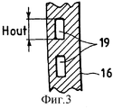
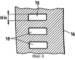
Согласно предпочтительному варианту осуществления настоящего изобретения высота входного участка (Hin на фиг.4) охлаждающего отверстия выходной кромки лопатки вдоль радиального направления лопатки меньше, чем относительная высота выходного участка (Hout на фиг.3).According to a preferred embodiment of the present invention, the height of the inlet portion (H in in FIG. 4) of the cooling hole of the outlet edge of the blade along the radial direction of the blade is less than the relative height of the outlet portion (H out in FIG. 3).
Согласно предпочтительному варианту осуществления настоящего изобретения с внутренней стороны лопатки имеются волнистые элементы, предназначенные для увеличения коэффициента теплообмена лопатки.According to a preferred embodiment of the present invention, wavy elements are provided on the inside of the blade to increase the heat transfer coefficient of the blade.
Система согласно изобретению имеет высокий коэффициент теплообмена вдоль всего охлаждающего отверстия, при этом внутри металла лопатки отсутствуют градиенты температуры.The system according to the invention has a high heat transfer coefficient along the entire cooling hole, with no temperature gradients inside the blade metal.
Согласно изобретению система охлаждения сопел имеет множество элементов для создания турбулентности вдоль стенок самих отверстий, с тем чтобы всегда гарантировать высокое значение коэффициента теплообмена.According to the invention, the nozzle cooling system has many elements for creating turbulence along the walls of the holes themselves, in order to always guarantee a high heat transfer coefficient.
Кроме того, система охлаждения сопел имеет пониженные потери нагрузки, отнесенные к устью отверстия, чтобы избежать потери части полного давления регулировочного воздуха в этой зоне, с оставлением охлаждающей текучей среде большей энергии для преодоления потерь нагрузки в охлаждающих отверстиях и в элементах для создания турбулентности.In addition, the nozzle cooling system has reduced load losses attributed to the mouth of the hole in order to avoid losing part of the total pressure of the control air in this area, leaving more energy to the cooling fluid to overcome the load loss in the cooling holes and in the elements to create turbulence.
Наконец, следует заметить, что геометрическая форма отверстия такова, чтобы облегчить введение сплава в расплавленном состоянии в течение литья лопатки.Finally, it should be noted that the geometrical shape of the hole is such as to facilitate the introduction of the alloy in the molten state during casting of the blade.
Дополнительные отличительные признаки изобретения определены в других пунктах формулы изобретения, прилагаемых к настоящей заявке на патент.Additional features of the invention are defined in other claims appended to this patent application.
Отличительные признаки и преимущества настоящего изобретения будут более очевидны из приведенного ниже описания примера типичного варианта осуществления изобретения, не налагающего каких-либо ограничений, со ссылками на прилагаемые схематические чертежи, на которых:Distinctive features and advantages of the present invention will be more apparent from the following description of an example of a typical embodiment of the invention, without imposing any restrictions, with reference to the accompanying schematic drawings, in which:
на фиг.1 в продольном сечении схематически представлена лопатка, которая принадлежит соплу газовой турбины согласно известному уровню техники;figure 1 in longitudinal section schematically shows a blade that belongs to a nozzle of a gas turbine according to the prior art;
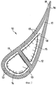
на фиг.2, с другой стороны, представлен вид в продольном сечении лопатки, принадлежащей соплу газовой турбины согласно настоящему изобретению;figure 2, on the other hand, is a view in longitudinal section of a blade belonging to the nozzle of a gas turbine according to the present invention;
на фиг.3 в радиальном поперечном сечении представлен выходной участок охлаждающих отверстий сопла газовой турбины согласно настоящему изобретению;figure 3 in radial cross section presents the output section of the cooling holes of the nozzles of a gas turbine according to the present invention;
на фиг.4 в радиальном поперечном сечении представлен входной участок охлаждающих отверстий сопла газовой турбины согласно настоящему изобретению.figure 4 in radial cross section presents the inlet portion of the cooling holes of the nozzles of a gas turbine according to the present invention.
В предлагаемом описании термин "радиальное направление", в частности, относится к направлению, перпендикулярному потоку газа, который расширяется в машине.In the proposed description, the term "radial direction", in particular, refers to the direction perpendicular to the flow of gas, which expands in the machine.
В некоторых случаях направление потока газа также представляет собой направление главной оси машины.In some cases, the direction of gas flow also represents the direction of the main axis of the machine.
Если прежде всего обратиться к фиг.2, то на ней показано продольное сечение лопатки, в целом обозначенной позицией 10, которая принадлежит соплу газовой турбины согласно настоящему изобретению.If you first turn to figure 2, then it shows a longitudinal section of the blade, generally indicated by 10, which belongs to the nozzle of a gas turbine according to the present invention.
Форма лопатки 10 главным образом предназначена для обеспечения требуемых аэродинамических свойств в случае газов, которые участвуют в процессе, происходящем в турбине, при этом лопатка имеет вогнутую или брюшную поверхность 11 и противоположную выпуклую или спинную поверхность 12, которые объединены для образования наружной формы лопатки 10.The shape of the
Также выполнено множество охлаждающих отверстий 13, которые находятся в соответствующих местах поверхности лопатки 10.Also made
Внутри лопатки 10 также имеются небольшие вкладыши 14 и 15, то есть перфорированные пластинчатые элементы, которые повышают коэффициент теплообмена до значений, которые приемлемы для применения в настоящее время.Inside the
Для задач предлагаемого изобретения особенно важна выходная кромка 16 лопатки 10, с внутренней стороны которой выполнено охлаждающее отверстие 17, имеющее входной участок 18, который увеличен по сравнению с известными техническими решениями.For the objectives of the invention, the
На фиг.2 также показан выходной участок 19 охлаждающего отверстия 17, в части которого лопатка 10 становится тоньше.Figure 2 also shows the
Следовательно, в случае этой конфигурации получается увеличение входного участка 18 охлаждающих отверстий 17 лопатки 10.Therefore, in the case of this configuration, an increase in the
Чтобы исключить этот недостаток, охлаждающие отверстия, которые обычно имеют постоянное поперечное сечение, могут иметь высоту, изменяющуюся в радиальном направлении.To eliminate this disadvantage, cooling holes, which usually have a constant cross section, can have a height that varies in the radial direction.
Фактически, если вход охлаждающего отверстия шире (зона 18 на фиг.2) в плоскости фигуры, размер под прямыми углами к самой плоскости (радиальное направление для машины) может быть меньше, чем в обычных случаях.In fact, if the inlet of the cooling hole is wider (
Фактически, входной участок 18 охлаждающего отверстия 17 выходной кромки 16 лопатки 10 имеет размер (обозначенный на фиг.4 как Hin), который меньше, чем соответствующий размер (указанный на фиг.3 как Hout) выходного участка 19.In fact, the
Если система охлаждения для сопла, выполненная согласно данному изобретению, также отличается таким же размером охлаждающего отверстия вблизи от выходной кромки лопатки (зона 29 на фиг.1 и зона 19 на фиг.2), то этим будет допущена исключительно трехразмерная форма с входным участком 18 и выходным участком 19, указанными на фиг.3-4.If the cooling system for the nozzle made according to this invention also differs in the same size of the cooling hole close to the outlet edge of the blade (zone 29 in figure 1 and
Следовательно, посредством этой геометрической формы можно получить высокие коэффициенты теплообмена вдоль всего охлаждающего отверстия 17 с исключением при этом градиентов температуры внутри металла лопатки.Therefore, through this geometric shape, high heat transfer coefficients can be obtained along the
Дальнейшее улучшение теплообмена также может быть достигнуто посредством использования элементов для создания турбулентности вдоль стенок самих отверстий, с тем чтобы всегда гарантировать высокое значение коэффициента теплообмена.Further improvement in heat transfer can also be achieved by using elements to create turbulence along the walls of the holes themselves, in order to always guarantee a high heat transfer coefficient.
Дополнительное преимущество изобретения заключается в уменьшении потери нагрузки, отнесенной к устью отверстия, что позволяет избежать излишне расходуемой части полного давления регулировочного воздуха в этой зоне, оставляя при этом охлаждающей текучей среде больше энергии для преодоления потерь нагрузки в охлаждающих отверстиях и элементах для создания турбулентности.An additional advantage of the invention is to reduce the load loss attributed to the mouth of the hole, which avoids the unnecessarily spent part of the total pressure of the control air in this zone, while leaving more cooling energy for the cooling fluid to overcome the load losses in the cooling holes and elements to create turbulence.
Еще одно преимущество изобретения обеспечивается в течение литья лопатки, в которой рассматриваемая геометрическая форма формирует тип воронки в зоне устья прорезей, которая облегчает вход расплавленного сплава.Another advantage of the invention is provided during casting of the blade, in which the geometric shape in question forms a type of funnel in the area of the mouth of the slots, which facilitates the entry of the molten alloy.
Теоретические и экспериментальные результаты, обеспечиваемые настоящим изобретением, настолько удовлетворительны, что система может быть использована для новых газовых турбин, которые имеют широкое применение.The theoretical and experimental results provided by the present invention are so satisfactory that the system can be used for new gas turbines that are widely used.
Составленное описание делает очевидными отличительные признаки и преимущества системы охлаждения сопел статора газовых турбин, выполненной согласно настоящему изобретению.The description made obvious the distinguishing features and advantages of the cooling system of the nozzles of the stator of gas turbines made according to the present invention.
Далее приведены заключительные комментарии и наблюдения, чтобы более точно и ясно охарактеризовать упомянутые преимущества.The following are concluding comments and observations to more accurately and clearly describe the benefits mentioned.
Задачей предложенного решения является уменьшение значительной толщины материала вблизи от охлаждающего отверстия выходной кромки лопатки.The objective of the proposed solution is to reduce a significant thickness of the material near the cooling hole of the outlet edge of the blade.
Таким образом, настоящее изобретение позволяет исключить упомянутые зоны большой толщины материала, одновременно исключая соответствующие градиенты температуры.Thus, the present invention eliminates the above-mentioned zones of large thickness of the material, while eliminating the corresponding temperature gradients.
Это приводит к предпочтительным результатам, ранее упомянутым с указанием на уменьшенные потери нагрузки, отнесенные к устью отверстия 17, чтобы избежать излишнего расходования части полного давления регулировочного воздуха в этой особенно критической зоне.This leads to the preferred results previously mentioned with reference to reduced load losses attributed to the mouth of the
Геометрия отверстия 17 такова, что она облегчает введение расплавленного сплава в течение литья лопатки 10.The geometry of the
Наконец, очевидно, что могут быть выполнены многие другие варианты системы охлаждения для сопел статора газовых турбин, которая составляет предмет настоящего изобретения, но без отклонения от принципов новизны, которые свойственны концепции, содержащей изобретательскую деятельность.Finally, it is obvious that many other cooling system options for gas turbine stator nozzles can be implemented, which is the subject of the present invention, but without deviating from the principles of novelty that are characteristic of the concept containing inventive activity.
Также очевидно, что в практическом варианте осуществления изобретения могут быть использованы любые материалы, размеры и формы, соответствующие предъявляемым требованиям, а сами компоненты могут быть заменены другими компонентами, которые в техническом отношении эквивалентны им.It is also obvious that in a practical embodiment of the invention, any materials, sizes and shapes that meet the requirements can be used, and the components themselves can be replaced by other components that are technically equivalent to them.
Объем настоящего изобретения определяется прилагаемыми пунктами формулы изобретения.The scope of the present invention is defined by the attached claims.
Claims (3)
Applications Claiming Priority (2)
| Application Number | Priority Date | Filing Date | Title |
|---|---|---|---|
| IT2000MI002555A IT1319140B1 (en) | 2000-11-28 | 2000-11-28 | REFRIGERATION SYSTEM FOR STATIC GAS TURBINE NOZZLES |
| ITMI2000A002555 | 2000-11-28 |
Publications (2)
| Publication Number | Publication Date |
|---|---|
| RU2001132142A RU2001132142A (en) | 2003-06-20 |
| RU2286464C2 true RU2286464C2 (en) | 2006-10-27 |
Family
ID=11446145
Family Applications (1)
| Application Number | Title | Priority Date | Filing Date |
|---|---|---|---|
| RU2001132142/06A RU2286464C2 (en) | 2000-11-28 | 2001-11-27 | Cooling system of gas-turbine stator nozzles |
Country Status (9)
| Country | Link |
|---|---|
| US (1) | US6530745B2 (en) |
| EP (1) | EP1209323B1 (en) |
| JP (1) | JP4154509B2 (en) |
| KR (1) | KR100705859B1 (en) |
| CA (1) | CA2363363C (en) |
| DE (1) | DE60117494T2 (en) |
| IT (1) | IT1319140B1 (en) |
| RU (1) | RU2286464C2 (en) |
| TW (1) | TW575711B (en) |
Cited By (2)
| Publication number | Priority date | Publication date | Assignee | Title |
|---|---|---|---|---|
| RU2740069C1 (en) * | 2017-12-01 | 2020-12-31 | Сименс Энерджи, Инк. | Soldered heat transfer element for cooled components of turbine |
| RU2767580C1 (en) * | 2021-11-29 | 2022-03-17 | Акционерное общество "Объединенная двигателестроительная корпорация" (АО "ОДК") | Cooled nozzle blade of a high-pressure turbine of a turbojet engine |
Families Citing this family (14)
| Publication number | Priority date | Publication date | Assignee | Title |
|---|---|---|---|---|
| KR100916354B1 (en) | 2009-02-27 | 2009-09-11 | 한국기계연구원 | Turbine blade and turbine using it |
| US9051842B2 (en) * | 2012-01-05 | 2015-06-09 | General Electric Company | System and method for cooling turbine blades |
| GB2502302A (en) * | 2012-05-22 | 2013-11-27 | Bhupendra Khandelwal | Gas turbine nozzle guide vane with dilution air exhaust ports |
| EP2733309A1 (en) * | 2012-11-16 | 2014-05-21 | Siemens Aktiengesellschaft | Turbine blade with cooling arrangement |
| US9394797B2 (en) | 2012-12-04 | 2016-07-19 | General Electric Company | Turbomachine nozzle having fluid conduit and related turbomachine |
| FR3021698B1 (en) * | 2014-05-28 | 2021-07-02 | Snecma | TURBINE BLADE, INCLUDING A CENTRAL COOLING DUCT THERMALLY INSULATED FROM THE BLADE WALLS BY TWO JOINT SIDE CAVITIES DOWNSTREAM FROM THE CENTRAL DUCT |
| US10436048B2 (en) * | 2016-08-12 | 2019-10-08 | General Electric Comapny | Systems for removing heat from turbine components |
| US10408062B2 (en) * | 2016-08-12 | 2019-09-10 | General Electric Company | Impingement system for an airfoil |
| US10364685B2 (en) * | 2016-08-12 | 2019-07-30 | Gneral Electric Company | Impingement system for an airfoil |
| US10443397B2 (en) * | 2016-08-12 | 2019-10-15 | General Electric Company | Impingement system for an airfoil |
| US20190071977A1 (en) * | 2017-09-07 | 2019-03-07 | General Electric Company | Component for a turbine engine with a cooling hole |
| US11261739B2 (en) * | 2018-01-05 | 2022-03-01 | Raytheon Technologies Corporation | Airfoil with rib communication |
| US11280201B2 (en) * | 2019-10-14 | 2022-03-22 | Raytheon Technologies Corporation | Baffle with tail |
| WO2023211485A2 (en) * | 2021-10-22 | 2023-11-02 | Raytheon Technologies Corporation | Gas turbine engine article with cooling holes for mitigating recession |
Family Cites Families (14)
| Publication number | Priority date | Publication date | Assignee | Title |
|---|---|---|---|---|
| FR2098558A5 (en) * | 1970-07-20 | 1972-03-10 | Onera (Off Nat Aerospatiale) | |
| US4303374A (en) * | 1978-12-15 | 1981-12-01 | General Electric Company | Film cooled airfoil body |
| US4297077A (en) * | 1979-07-09 | 1981-10-27 | Westinghouse Electric Corp. | Cooled turbine vane |
| GB2159585B (en) * | 1984-05-24 | 1989-02-08 | Gen Electric | Turbine blade |
| JPH03182602A (en) * | 1989-12-08 | 1991-08-08 | Hitachi Ltd | Gas turbine blade with cooling passage and cooling passage machining method thereof |
| US5681144A (en) * | 1991-12-17 | 1997-10-28 | General Electric Company | Turbine blade having offset turbulators |
| US5337805A (en) * | 1992-11-24 | 1994-08-16 | United Technologies Corporation | Airfoil core trailing edge region |
| US5368441A (en) * | 1992-11-24 | 1994-11-29 | United Technologies Corporation | Turbine airfoil including diffusing trailing edge pedestals |
| US5352091A (en) * | 1994-01-05 | 1994-10-04 | United Technologies Corporation | Gas turbine airfoil |
| US5503527A (en) * | 1994-12-19 | 1996-04-02 | General Electric Company | Turbine blade having tip slot |
| JP3786458B2 (en) * | 1996-01-19 | 2006-06-14 | 株式会社東芝 | Axial turbine blade |
| US6190120B1 (en) * | 1999-05-14 | 2001-02-20 | General Electric Co. | Partially turbulated trailing edge cooling passages for gas turbine nozzles |
| US6164913A (en) * | 1999-07-26 | 2000-12-26 | General Electric Company | Dust resistant airfoil cooling |
| US6179565B1 (en) * | 1999-08-09 | 2001-01-30 | United Technologies Corporation | Coolable airfoil structure |
-
2000
- 2000-11-28 IT IT2000MI002555A patent/IT1319140B1/en active
-
2001
- 2001-11-14 US US09/987,331 patent/US6530745B2/en not_active Expired - Fee Related
- 2001-11-15 CA CA002363363A patent/CA2363363C/en not_active Expired - Fee Related
- 2001-11-21 DE DE60117494T patent/DE60117494T2/en not_active Expired - Lifetime
- 2001-11-21 EP EP01309788A patent/EP1209323B1/en not_active Expired - Lifetime
- 2001-11-27 KR KR1020010074116A patent/KR100705859B1/en active IP Right Grant
- 2001-11-27 RU RU2001132142/06A patent/RU2286464C2/en active
- 2001-11-28 JP JP2001361874A patent/JP4154509B2/en not_active Expired - Lifetime
- 2001-11-28 TW TW90129416A patent/TW575711B/en not_active IP Right Cessation
Cited By (3)
| Publication number | Priority date | Publication date | Assignee | Title |
|---|---|---|---|---|
| RU2740069C1 (en) * | 2017-12-01 | 2020-12-31 | Сименс Энерджи, Инк. | Soldered heat transfer element for cooled components of turbine |
| US11346246B2 (en) | 2017-12-01 | 2022-05-31 | Siemens Energy, Inc. | Brazed in heat transfer feature for cooled turbine components |
| RU2767580C1 (en) * | 2021-11-29 | 2022-03-17 | Акционерное общество "Объединенная двигателестроительная корпорация" (АО "ОДК") | Cooled nozzle blade of a high-pressure turbine of a turbojet engine |
Also Published As
| Publication number | Publication date |
|---|---|
| EP1209323A2 (en) | 2002-05-29 |
| DE60117494T2 (en) | 2006-10-26 |
| US6530745B2 (en) | 2003-03-11 |
| JP2002195005A (en) | 2002-07-10 |
| KR100705859B1 (en) | 2007-04-09 |
| KR20020041756A (en) | 2002-06-03 |
| US20020064452A1 (en) | 2002-05-30 |
| TW575711B (en) | 2004-02-11 |
| DE60117494D1 (en) | 2006-04-27 |
| JP4154509B2 (en) | 2008-09-24 |
| CA2363363C (en) | 2008-06-17 |
| EP1209323A3 (en) | 2004-02-04 |
| EP1209323B1 (en) | 2006-03-01 |
| CA2363363A1 (en) | 2002-05-28 |
| IT1319140B1 (en) | 2003-09-23 |
| ITMI20002555A1 (en) | 2002-05-28 |
Similar Documents
| Publication | Publication Date | Title |
|---|---|---|
| RU2286464C2 (en) | Cooling system of gas-turbine stator nozzles | |
| US6428273B1 (en) | Truncated rib turbine nozzle | |
| CN105464714B (en) | Cooling scheme for turbine blades of a gas turbine | |
| US5394687A (en) | Gas turbine vane cooling system | |
| US6746209B2 (en) | Methods and apparatus for cooling gas turbine engine nozzle assemblies | |
| US10378380B2 (en) | Segmented micro-channel for improved flow | |
| US20110217179A1 (en) | Turbine airfoil fillet cooling system | |
| EP2412934B1 (en) | Turbine stage shroud segment | |
| GB2553663A (en) | A combustion chamber assembly and a combustion chamber segment | |
| US6224329B1 (en) | Method of cooling a combustion turbine | |
| EP3181825B1 (en) | Shroud segment with hook-shaped cooling channels | |
| EP3181826B1 (en) | Shroud segment with trailing edge cooling channels and hook-shaped side edge cooling channels | |
| EP3228821A1 (en) | System and method for cooling trailing edge and/or leading edge of hot gas flow path component | |
| JP2013139804A (en) | System and method for cooling turbine blade | |
| US20170175576A1 (en) | System and method for utilizing target features in forming inlet passages in micro-channel circuit | |
| US20170175574A1 (en) | Method for metering micro-channel circuit | |
| WO2019002274A1 (en) | A turbomachine component and method of manufacturing a turbomachine component | |
| EP3184736A1 (en) | Angled heat transfer pedestal | |
| KR101289613B1 (en) | Shroud for a gas turbine | |
| US11230931B1 (en) | Inserts for airfoils of gas turbine engines | |
| JPS6327524B2 (en) | ||
| WO2020050854A1 (en) | Angular cooling channels for improved mechanical life | |
| JPH08177529A (en) | Gas turbine |