EP2010402B1 - Vehicule a trois roues - Google Patents
Vehicule a trois roues Download PDFInfo
- Publication number
- EP2010402B1 EP2010402B1 EP07731187A EP07731187A EP2010402B1 EP 2010402 B1 EP2010402 B1 EP 2010402B1 EP 07731187 A EP07731187 A EP 07731187A EP 07731187 A EP07731187 A EP 07731187A EP 2010402 B1 EP2010402 B1 EP 2010402B1
- Authority
- EP
- European Patent Office
- Prior art keywords
- wheels
- wheel
- axle
- propulsion
- axles
- Prior art date
- Legal status (The legal status is an assumption and is not a legal conclusion. Google has not performed a legal analysis and makes no representation as to the accuracy of the status listed.)
- Not-in-force
Links
Images


Classifications
-
- B—PERFORMING OPERATIONS; TRANSPORTING
- B62—LAND VEHICLES FOR TRAVELLING OTHERWISE THAN ON RAILS
- B62D—MOTOR VEHICLES; TRAILERS
- B62D31/00—Superstructures for passenger vehicles
- B62D31/003—Superstructures for passenger vehicles compact cars, e.g. city cars
-
- B—PERFORMING OPERATIONS; TRANSPORTING
- B60—VEHICLES IN GENERAL
- B60G—VEHICLE SUSPENSION ARRANGEMENTS
- B60G3/00—Resilient suspensions for a single wheel
- B60G3/02—Resilient suspensions for a single wheel with a single pivoted arm
- B60G3/12—Resilient suspensions for a single wheel with a single pivoted arm the arm being essentially parallel to the longitudinal axis of the vehicle
- B60G3/14—Resilient suspensions for a single wheel with a single pivoted arm the arm being essentially parallel to the longitudinal axis of the vehicle the arm being rigid
-
- B—PERFORMING OPERATIONS; TRANSPORTING
- B62—LAND VEHICLES FOR TRAVELLING OTHERWISE THAN ON RAILS
- B62D—MOTOR VEHICLES; TRAILERS
- B62D61/00—Motor vehicles or trailers, characterised by the arrangement or number of wheels, not otherwise provided for, e.g. four wheels in diamond pattern
- B62D61/02—Motor vehicles or trailers, characterised by the arrangement or number of wheels, not otherwise provided for, e.g. four wheels in diamond pattern with two road wheels in tandem on the longitudinal centre line of the vehicle
- B62D61/04—Motor vehicles or trailers, characterised by the arrangement or number of wheels, not otherwise provided for, e.g. four wheels in diamond pattern with two road wheels in tandem on the longitudinal centre line of the vehicle with two other wheels which are coaxial
Definitions
- the present invention relates to a propulsion and its associated vehicle suspension.
- the invention particularly suitable for urban vehicles or small vehicles designed for one or two people.
- the invention having the objective of providing maneuverability, agility and flexibility of use.
- the invention finding a particular application for urban driving particularly suitable for developing countries.
- the document GB 122923 exposes a vehicle having a rear axle comprising three wheels.
- a main objective of the invention is to provide a vehicle propulsion that is practical, manageable, adaptable to different pavement quality.
- An object of the invention is to provide a lightweight propulsion that allows a minimum projected surface ground so as to make the vehicle as compact as possible.
- the compactness of this vehicle allows it to better sneak and evolve more easily on the road to other vehicles.
- An object of the invention is to propose a propulsion adapted for a single user. This solution offers obvious energy savings while providing the user with the same amenities as a traditional low-displacement car.
- An object of the invention is to provide a propulsion and motorization that is economical to manufacture.
- the invention proposing an engine that is manufactured in the scooter industry and proposes its adaptation on a four-wheeled vehicle. The assembly of parts between them requiring a minimum of human intervention.
- the vehicle and its propulsion having qualities of robustness and lightness for energy savings.
- An object of the invention is to provide a propulsion and its engine that meets the safety standards in force and has features of user protection.
- the invention proposes a three-wheel rear train with a motorized propulsion wheel and two balance wheels positioned on either side of the propulsion wheel.
- the rear wheel train comprises a shock absorber game and a linkage set articulated between the wheels. This game allows a great adaptability to the dented terrain.
- the motorization of a traditional scooter type 80 cm 3 or 125 cm3 or more can be adapted according to the invention to propel an urban vehicle one or two people at speeds and with a power that not less than that of a corresponding scooter.
- the invention thus making it possible to have a fast, agile and economical vehicle for one or two people, particularly adapted to the urban environment or to short or medium distances.
- the Figure 1 represents a rear view of the rear wheel train (11a, 11b, 12) made by a propulsion wheel (12) and two balance wheels (11a, 11b) which are neutral or non-motorized.
- a propulsion wheel (12) Preferably for balancing reasons, it is the central wheel which is the propulsion wheel (12), the two balance wheels (11) being positioned on either side symmetrically on each side of the propulsion wheel. (12).
- Each of the wheels (11a, 11b, 12) is retained to the frame by a wheel support (15) to the frame (10) more particularly described in Figures 2a , 2b .
- a main feature of the invention resides in the fact that the three wheels are aligned and connected between them two by two by an axle (14a, 14b). The two rear axles are each articulated with the wheel at its steering axis to adapt to the soil constraints as described.
- Each rear axle axle (14a, 14b) is connected to the chassis by a shock absorber (13a, 13b) of axles.
- the position of the two dampers being symmetrical about the propulsion wheel (12).
- the dampers slide adjustably along the axles (14a, 14b) and along the frame (10).
- the position of the dampers to increase or decrease the load borne by the propulsion wheel (12) so as to increase or decrease its adhesion to the ground. This adjustment is easy and can for example be adjusted by the user according to the driving characteristics he chooses, soil quality, driver weight, nature of driving.
- the figure 3 is a top view of the rear wheel set and its connection to the chassis (10) by the wheel retainers (15) to the chassis (10) and how the three wheels are aligned and connected in pairs by axles (14) the connection of the axles (14a, 14b) with the propulsion wheel (12) being an articulated connection (30a, 30b), as well as the connection of the axles (14a, 14b) with the balance wheels (12) according to the articulated links (31a, 31b).
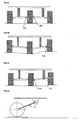
- the Figures 4a, 4b and 4c represent three views of damping situation of the rear wheel set according to three different ground conditions.
- Figure 4a positive elevation under the propulsion wheel (12), and thus compression of the axle dampers (13a, 13b) and rotation of the articulated links of axles (30a, 30b) propulsion wheel (12).
- Figure 4b slight negative drop under the propulsion wheel (12) and positive elevation under the right balance wheel (11b), and thus expansion of the left axle damper (13a) and compression of the right axle damper (13b) and rotation of the articulated axle links (30a, 30b) of the propulsion wheel (12) and rotation in one direction of the articulated axle connection (31b) of right balance wheel (11b) and rotation in an opposite direction of the articulated axle connection (3 1 a) of the left-hand balance wheel (11a).
- FIG 4c positive elevation under the right balance wheel (11b), and therefore compression of the right axle dampers (13b) and rotation of the right articulated axle connection (30b) of the propulsion wheel (12) and rotation of the articulated axle link (31b) of the right balance wheel (11b).
- the figure 5 represents a rear view of the rear wheel set with a particular engine (50, 51) which comprises a motor (50) and a muffler (51) of a shape asymmetrical to that of the motor (50).
- This connection is rigid while being articulated (30b, 31b) at each of its ends. This type of connection to adapt to any type of engine volume or equipment desired by the manufacturer.
- the figure 6 represents a view of a vehicle (1) one or two people particularly suitable for this three-wheeled rear wheel drive, one or two people, urban vehicle of small size, easy to handle and low in energy, and which adapts a known engine of scooter type.
- the invention thus relates to a rear wheel train for vehicle (1) one or two persons comprising a rear wheel train (11, 12) and a two-wheel front train mounted on a chassis (10) characterized in that the train of rear wheels (11, 12) comprises a motorized propulsion wheel (12) positioned between two balance wheels (11a, 11b)
- the invention therefore relates to a rear wheel train for a vehicle (1) one or two persons characterized in that the three wheels (11, 12) of the rear axle are aligned and connected between them two by two by two axles (14a, 14b ) of the rear axle, each axle (14a, 14b) of the rear axle being hinged in its connection (30, 31) with the wheel (11, 12)
- the invention therefore relates to a rear wheel train for vehicle (1) one or two persons characterized in that each axle train rear (14a, 14b) is connected to the chassis by an axle damper (13a, 13b)
- the invention therefore relates to a rear wheel train for a vehicle (1) one or two persons characterized in that the axle dampers (13a, 13b) are positioned on the rear axle axles (14a, 14b) at an adjustable distance between the two wheels that they connect
- the invention thus relates to a rear wheel train for a vehicle (1) one or two persons characterized in that the rear axle axles (14a, 14b) adopt a particular rigid form of U-shaped which marries the outer volume of the pot exhaust (51) or a motorization device while being articulated (30b, 31b) at each of its ends in contact with the two wheels that it joins (11, 12)
- the invention therefore relates to a rear wheel train for vehicle (1) one or two persons characterized in that the propulsion wheel is made from the propulsion mechanism of a scooter
Description
- La présente invention concerne une propulsion et sa suspension associée pour véhicule. L'invention s'adaptant particulièrement aux véhicules urbains ou aux véhicules de petites tailles conçues pour une ou deux personnes. L'invention ayant comme objectif de proposer maniabilité, agilité et souplesse d'utilisation. L'invention trouvant une application particulière pour la conduite urbaine particulièrement adapté pour les pays en voie de développement.
- Il est connu de nombreux véhicules de petites tailles pour un ou plusieurs passagers. Certains véhicules sportifs sont conçus pour le tout terrain, ils offrent presque la même ergonomie d'utilisation qu'une moto. Ces véhicules sont peu maniables en ville et leur ergonomie de conduite rappelle plus celle d'une moto que celle d'une voiture. Leur conduite est donc mal aisée pour des citadins lambda. Les véhicules du type voiturette électrique pour le golf offrent un habitacle et une motorisation inadaptée pour la conduite citadine ou de déplacement court. Les voitures à motorisation essence ou électrique traditionnelles présentent des solutions onéreuses et lourdes. Il n'existe pas encore de voiture une ou deux places qui soit positionnée sur au moins quatre roues et qui propose une motorisation avec sa propulsion et son châssis qui soit économique et robuste..
- Le Document
GB 122923 - Un objectif principal de l'invention est de proposer une propulsion de véhicule qui soit pratique, maniable, adaptable aux différentes qualité de chaussées.
- Un objectif de l'invention est de proposer une propulsion légère qui permette une surface projetée au sol minimum de façon à rendre le véhicule le plus compact possible. La compacité de ce véhicule lui permettant de mieux se faufiler et d'évoluer avec plus de facilité sur la route aux milieux des autres véhicules.
- Un objectif de l'invention est de proposer une propulsion adaptée pour un seul utilisateur. Cette solution offrant des économies d'énergie évidentes tout en procurant à l'utilisateur les mêmes agréments qu'une voiture traditionnelle de faible cylindrée.
- Un objet de l'invention est de proposer une propulsion et une motorisation qui soit économique à la fabrication. l'invention proposant une motorisation qui est fabriquée dans l'industrie du scooter et propose son adaptation sur un véhicule quatre roues. Le montage des pièces entre elles nécessitant un minimum d'intervention humaine. Sous une forme préférentielle, le véhicule et sa propulsion présentant des qualités de robustesse et de légèreté pour les économies d'énergie.
- Un objet de l'invention étant de proposer une propulsion et sa motorisation qui réponde aux normes de sécurité en vigueur et qui présente des caractéristiques de protection de l'utilisateur.
- Dans un aspect principal l'invention propose un train de trois roues arrière avec une roue de propulsion motorisée et deux roues d'équilibre positionnées de part et d'autre de la roue de propulsion.
- Dans un aspect de l'invention, le train de roue arrière comprend un jeu d'amortisseur et un jeu de liaison articulée entre les roues. Ce jeu permettant une grande adaptabilité au terrain cabossé.
- Dans un aspect de l'invention, la motorisation d'un scooter traditionnel de type 80 cm 3 ou 125 cm3 ou plus peut être adapté selon l'invention pour propulser un véhicule urbain une ou deux personnes à des vitesses et avec une puissance qui ne sont pas minorées par rapport à celle d'un scooter correspondant. L'invention permettant ainsi de disposer d'un véhicule rapide, agile et économique pour une ou deux personnes, particulièrement adapté au milieu urbain ou au trajets de courtes ou moyennes distances.
- D'autres buts, caractéristiques et avantages de la présente invention ressortiront plus clairement de la description qui suit d'un exemple de réalisation donné à titre illustratif, en référence aux dessins annexés sur lesquels:
- La
Figure 1 représente une vue de dos du train de roues arrière selon l'invention - Les
figures 2a ,2b représentent deux vues de côté de la liaison d'une roue au châssis du véhicule selon deux situations de terrain - La
figure 3 représente une vue de dessus du train de roues arrière et de sa liaison au châssis - Les
figures 4a, 4b et 4c représentent trois vues de situation d'amortissement du train de roues arrières selon trois conditions de terrain différentes - La
figure 5 représente une vue de dos du train de roues arrière avec une motorisation particulière - La
figure 6 représente une vue d'un véhicule une ou deux personnes particulièrement adapté à cette propulsion de train arrière trois roues - La
Figure 1 représente une vue de dos du train de roues arrière (11a, 11b, 12) réalisé par une roue de propulsion (12) et deux roues d'équilibre (11a, 11b) qui sont neutres soit non motorisées. Préférentiellement pour des raisons d'équilibrage, c'est la roue centrale qui est la roue de propulsion (12), les deux roues d'équilibre (11) étant positionnées de part et d'autre symétriquement de chaque côté de la roue de propulsion (12). Chacune des roues (11a, 11b, 12) est retenue au châssis par un maintien de roue (15) au châssis (10) plus particulièrement décrit enfigures 2a ,2b . Chacune des roues (11, 12), qu'il s'agisse de la roue de propulsion (11) ou des d'équilibre (12) étant liée d'une façon traditionnelle par un longeron depuis l'arbre de rotation de roue (21) jusque sur une âme (22) positionnée sur le châssis (10). Pour que la roue (11, 12) puisse avoir un mouvement relatif par rapport au châssis (10) pour épouser la conduite au sol, le longeron de maintien est soit articulé selon ses extrémités de lien avec la roue et avec le châssis,figure 2a , soit comporte un dispositif d'amortissement incorporé,figure 2b . Une particularité principale de l'invention résidant dans le fait que les trois roues sont alignées et reliées entre elle deux à deux par un essieu (14a, 14b). Les deux essieux de train arrière étant chacun articulé avec la roue au niveau de son axe de direction à s'adapter aux contraintes de sol comme décritfigure 4a, 4b, 4c . Chaque essieux de train arrière (14a, 14b) étant lié au châssis par un amortisseur (13a, 13b) d'essieux. La position des deux amortisseurs étant symétrique autour de la roue de propulsion (12). Les amortisseurs coulissant de façon réglable le long des essieux (14a, 14b) et le long du châssis (10). La position des amortisseurs permettant d'augmenter ou de diminuer la charge supportée par la roue de propulsion (12) de façon à augmenter ou diminuer son adhérence sur le sol. Ce réglage étant facile et pouvant par exemple être réglé par l'utilisateur en fonction des caractéristiques de conduite qu'il choisira, qualité du sol, poids du conducteur, nature de la conduite. Lafigure 3 représente une vue de dessus du train de roues arrière et de sa liaison au châssis (10) par les maintiens de roues (15) au châssis (10) et comment les trois roues sont alignées et reliées deux à deux par des essieux (14), la liaison des essieux (14a, 14b) avec la roue de propulsion (12) étant une liaison articulée (30a, 30b), tout comme la liaison des essieux (14a, 14b) avec les roues d'équilibre (12) selon les liaisons articulées (31a, 31b). Lesfigures 4a, 4b et 4c représentent trois vues de situation d'amortissement du train de roues arrières selon trois conditions de terrain différentes.Figure 4a , dénivelé positif sous la roue de propulsion (12), et donc compression des amortisseurs d'essieux (13a, 13b) et rotation des liaisons articulées d'essieux (30a, 30b) de roue de propulsion (12).Figure 4b , léger dénivelé négatif sous la roue de propulsion (12) et dénivelé positif sous la roue d'équilibre droite (11b), et donc dilatation de l'amortisseur d'essieux gauche (13a) et compression de l'amortisseur d'essieux droit (13b) et rotation des liaisons articulées d'essieux (30a, 30b) de roue de propulsion (12) et rotation en un sens de la liaison articulée d'essieux (31b) de roue d'équilibre droite (11b) et rotation en un sens opposé de la liaison articulée d'essieux (3 1 a) de roue d'équilibre gauche (11a).Figure 4c , dénivelé positif sous la roue d'équilibre droite (11b), et donc compression de l'amortisseurs d'essieux droit (13b) et rotation des de la liaison articulée droite d'essieux (30b) de roue de propulsion (12) et rotation de la liaison articulée d'essieux (31b) de roue d'équilibre droite (11b). Lafigure 5 représente une vue de dos du train de roues arrière avec une motorisation particulière (50, 51) qui comprend un moteur (50) et un pot d'échappement (51) d'une forme asymétrique à celle du moteur (50). Le volume du pot d'échappement (51) empiétant sur la ligne virtuelle qui relie le centre de rotation de la roue de propulsion (12) à la roue d'équilibre droite(11b), ce qui fait que sous cette forme les essieux de liaison droit (14b) adopte une forme particulière rigide du type en U qui épouse le volume extérieur du pot d'échappement (51). Le principal étant que cette liaison soit rigide tout en étant articulée (30b, 31b) à chacune de ses extrémités. Ce type de liaison permettant de s'adapter à tout type de volume de motorisation ou d'équipement souhaité par le constructeur. Lafigure 6 représente une vue d'un véhicule (1) une ou deux personnes particulièrement adapté à cette propulsion de train arrière trois roues, une ou deux personnes, véhicule urbain de petite taille, maniable et peu gourmand en énergie, et qui adapte une motorisation connue de type scooter. - L'invention concerne donc un train de roues arrière pour véhicule (1) une ou deux personnes comprenant un train de roues arrières (11, 12) et un train de deux roues avant monté sur un châssis (10) caractérisé en ce que le train de roues arrières (11, 12) comprend une roue de propulsion motorisée (12) positionnée entre deux roues d'équilibre (11a, 11b)
- L'invention concerne donc un train de roues arrière pour véhicule (1) une ou deux personnes caractérisé en ce que les trois roues (11, 12) du train arrière sont alignées et reliées entre elle deux à deux par deux essieux (14a, 14b) de train arrière, chaque essieu (14a, 14b) de train arrière étant articulé dans sa liaison (30, 31) avec la roue (11, 12)
- L'invention concerne donc un train de roues arrière pour véhicule (1) une ou deux personnes caractérisé en ce que chaque essieu de train arrière (14a, 14b) est lié au châssis par un amortisseur (13a, 13b) d'essieux
- L'invention concerne donc un train de roues arrière pour véhicule (1) une ou deux personnes caractérisé en ce que les amortisseurs d'essieux (13a, 13b) sont positionnés sur les essieux (14a, 14b) de train arrière à une distance réglable entre les deux roues qu'ils relient
- L'invention concerne donc un train de roues arrière pour véhicule (1) une ou deux personnes caractérisé en ce que les essieux de train arrière (14a, 14b) adoptent une forme particulière rigide du type en U qui épouse le volume extérieur du pot d'échappement (51) ou d'un équipement de motorisation tout en étant articulée (30b, 31b) à chacune de ses extrémités en contact avec les deux roues qu'il rejoint (11, 12)
- L'invention concerne donc un train de roues arrière pour véhicule (1) une ou deux personnes caractérisé en ce que la roue de propulsion est réalisé à partir du mécanisme de propulsion d'un scooter
- On voit donc bien que de nombreuses variantes éventuellement susceptibles de se combiner peuvent être ici apportées sans jamais sortir du cadre de l'invention tel qu'il est défini ci-après.
Claims (5)
- Train de roues arrière pour véhicule (1) une ou deux personnes comprenant un train de roues arrières (11, 12) et un train de deux roues avant monté sur un châssis (10), le train de roues arrières (11, 12) comprend une roue de propulsion motorisée (12) positionnée entre deux roues d'équilibre (11a, 11b) caractérisé en ce que les trois roues (11, 12) du train arrière sont alignées et reliées entre elle deux à deux par deux essieux (14a, 14b) de train arrière, chaque essieu (14a, 14b) de train arrière étant articulé dans sa liaison (30, 31) avec chacune des roues (11, 12)
- Train de roues arrière pour véhicule (1) une ou deux personnes selon la revendication 1 caractérisé en ce que chaque essieu de train arrière (14a, 14b) est lié au châssis par un amortisseur (13a, 13b) d'essieux
- Train de roues arrière pour véhicule (1) une ou deux personnes selon la revendication 1 caractérisé en ce que les amortisseurs d'essieux (13a, 13b) sont positionnés sur les essieux (14a, 14b) de train arrière à une distance réglable entre les deux roues qu'ils relient
- Train de roues arrière pour véhicule (1) une ou deux personnes selon la revendication 1 caractérisé en ce que les essieux de train arrière (14a, 14b) adoptent une forme particulière rigide du type en U qui épouse le volume extérieur du pot d'échappement (51) ou d'un équipement de motorisation tout en étant articulée (30b, 31b) à chacune de ses extrémités en contact avec les deux roues qu'il rejoint (11, 12)
- Train de roues arrière pour véhicule (1) une ou deux personnes selon la revendication 1 caractérisé en ce que la roue de propulsion est réalisé à partir du mécanisme de propulsion d'un scooter
Applications Claiming Priority (2)
| Application Number | Priority Date | Filing Date | Title |
|---|---|---|---|
| FR0602907A FR2899148B1 (fr) | 2006-04-04 | 2006-04-04 | Train de trois roues arriere pour vehicule |
| PCT/FR2007/000499 WO2007118959A1 (fr) | 2006-04-04 | 2007-03-23 | Vehicule a trois roues |
Publications (2)
| Publication Number | Publication Date |
|---|---|
| EP2010402A1 EP2010402A1 (fr) | 2009-01-07 |
| EP2010402B1 true EP2010402B1 (fr) | 2010-10-20 |
Family
ID=37116247
Family Applications (1)
| Application Number | Title | Priority Date | Filing Date |
|---|---|---|---|
| EP07731187A Not-in-force EP2010402B1 (fr) | 2006-04-04 | 2007-03-23 | Vehicule a trois roues |
Country Status (5)
| Country | Link |
|---|---|
| EP (1) | EP2010402B1 (fr) |
| AT (1) | ATE485181T1 (fr) |
| DE (1) | DE602007009959D1 (fr) |
| FR (1) | FR2899148B1 (fr) |
| WO (1) | WO2007118959A1 (fr) |
Cited By (1)
| Publication number | Priority date | Publication date | Assignee | Title |
|---|---|---|---|---|
| CN102529685A (zh) * | 2011-01-04 | 2012-07-04 | 潘登 | 双轮非对称反向平行悬挂厢式电动车 |
Families Citing this family (1)
| Publication number | Priority date | Publication date | Assignee | Title |
|---|---|---|---|---|
| CN108995744B (zh) * | 2018-08-30 | 2021-02-02 | 安徽凌坤智能科技有限公司 | 一种agv设备的差速驱动装置 |
Family Cites Families (5)
| Publication number | Priority date | Publication date | Assignee | Title |
|---|---|---|---|---|
| GB158838A (en) * | 1921-02-01 | 1922-05-01 | Eduard Tatschke | Improvements in or relating to motor vehicles |
| GB122923A (en) * | 1918-02-13 | 1919-02-13 | Albert Horrocks | Improvements in or appertaining to Motor Road Vehicles. |
| FR722026A (fr) * | 1931-08-28 | 1932-03-10 | Vehicule à cinq ou un plus grand nombre de roues | |
| US2005263A (en) * | 1933-03-20 | 1935-06-18 | Charles M Mclanahan | Motor vehicle drive |
| FR1228087A (fr) * | 1959-01-21 | 1960-08-26 | Voiture à cartouche interchangeable mixte |
-
2006
- 2006-04-04 FR FR0602907A patent/FR2899148B1/fr not_active Expired - Fee Related
-
2007
- 2007-03-23 EP EP07731187A patent/EP2010402B1/fr not_active Not-in-force
- 2007-03-23 AT AT07731187T patent/ATE485181T1/de not_active IP Right Cessation
- 2007-03-23 WO PCT/FR2007/000499 patent/WO2007118959A1/fr active Application Filing
- 2007-03-23 DE DE602007009959T patent/DE602007009959D1/de active Active
Cited By (1)
| Publication number | Priority date | Publication date | Assignee | Title |
|---|---|---|---|---|
| CN102529685A (zh) * | 2011-01-04 | 2012-07-04 | 潘登 | 双轮非对称反向平行悬挂厢式电动车 |
Also Published As
| Publication number | Publication date |
|---|---|
| WO2007118959A1 (fr) | 2007-10-25 |
| EP2010402A1 (fr) | 2009-01-07 |
| DE602007009959D1 (de) | 2010-12-02 |
| FR2899148B1 (fr) | 2009-02-06 |
| ATE485181T1 (de) | 2010-11-15 |
| FR2899148A1 (fr) | 2007-10-05 |
Similar Documents
| Publication | Publication Date | Title |
|---|---|---|
| US6203043B1 (en) | Four-wheel, human powered cycle | |
| US8672076B2 (en) | Motorcycle rear-wheels transmission and suspension system | |
| US20090289437A1 (en) | Vehicle with three wheels | |
| US10843758B2 (en) | Vehicle having a suspension assembly including a swing arm | |
| US20050012291A1 (en) | Three-wheel rolling vehicle with front two-wheel steering | |
| FR2494208A2 (fr) | Motocycle sans cadre a suspension avant par triangles superposes | |
| US6571893B2 (en) | Light vehicle for sporting and off-road biking | |
| JPH0530676B2 (fr) | ||
| US20100320023A1 (en) | Four wheel vehicle having a rotatable body section and method therefor | |
| US20080001377A1 (en) | Axle Assembly | |
| CN106573517A (zh) | 机动车 | |
| WO2019162714A1 (fr) | Tricycle pour transport de passagers et de marchandises | |
| US7309081B1 (en) | Four wheel off-road vehicle | |
| FR2617455A1 (fr) | Vehicule d'appoint a usage temporaire pour une personne occupant une station debout | |
| US11034409B2 (en) | Suspension assembly for a vehicle | |
| EP2010402B1 (fr) | Vehicule a trois roues | |
| FR2858963A1 (fr) | Chassis articule de tricycle automoteur adaptable en temps reel aux changements d'allure et de direction | |
| TW201542413A (zh) | 人力推進式車輛 | |
| JP5578627B2 (ja) | 4輪自転車の後輪駆動緩衝装置 | |
| WO2018037175A1 (fr) | Train avant de tricyle ou de triporteur | |
| US8733491B2 (en) | Method and apparatus for an offroad vehicle | |
| JP5049022B2 (ja) | サスペンションアーム構造 | |
| US20200290698A1 (en) | Child off-road vehicle | |
| JPH0129194Y2 (fr) | ||
| RU2792786C1 (ru) | Мотоцикл внедорожный полноприводный |
Legal Events
| Date | Code | Title | Description |
|---|---|---|---|
| PUAI | Public reference made under article 153(3) epc to a published international application that has entered the european phase |
Free format text: ORIGINAL CODE: 0009012 |
|
| 17P | Request for examination filed |
Effective date: 20081106 |
|
| AK | Designated contracting states |
Kind code of ref document: A1 Designated state(s): AT BE BG CH CY CZ DE DK EE ES FI FR GB GR HU IE IS IT LI LT LU LV MC MT NL PL PT RO SE SI SK TR |
|
| AX | Request for extension of the european patent |
Extension state: AL BA HR MK RS |
|
| GRAP | Despatch of communication of intention to grant a patent |
Free format text: ORIGINAL CODE: EPIDOSNIGR1 |
|
| GRAS | Grant fee paid |
Free format text: ORIGINAL CODE: EPIDOSNIGR3 |
|
| GRAA | (expected) grant |
Free format text: ORIGINAL CODE: 0009210 |
|
| AK | Designated contracting states |
Kind code of ref document: B1 Designated state(s): AT BE BG CH CY CZ DE DK EE ES FI FR GB GR HU IE IS IT LI LT LU LV MC MT NL PL PT RO SE SI SK TR |
|
| REG | Reference to a national code |
Ref country code: GB Ref legal event code: FG4D Free format text: NOT ENGLISH |
|
| REG | Reference to a national code |
Ref country code: CH Ref legal event code: EP |
|
| REG | Reference to a national code |
Ref country code: IE Ref legal event code: FG4D Free format text: LANGUAGE OF EP DOCUMENT: FRENCH |
|
| REF | Corresponds to: |
Ref document number: 602007009959 Country of ref document: DE Date of ref document: 20101202 Kind code of ref document: P |
|
| REG | Reference to a national code |
Ref country code: NL Ref legal event code: VDEP Effective date: 20101020 |
|
| LTIE | Lt: invalidation of european patent or patent extension |
Effective date: 20101020 |
|
| PG25 | Lapsed in a contracting state [announced via postgrant information from national office to epo] |
Ref country code: LT Free format text: LAPSE BECAUSE OF FAILURE TO SUBMIT A TRANSLATION OF THE DESCRIPTION OR TO PAY THE FEE WITHIN THE PRESCRIBED TIME-LIMIT Effective date: 20101020 |
|
| REG | Reference to a national code |
Ref country code: IE Ref legal event code: FD4D |
|
| PG25 | Lapsed in a contracting state [announced via postgrant information from national office to epo] |
Ref country code: NL Free format text: LAPSE BECAUSE OF FAILURE TO SUBMIT A TRANSLATION OF THE DESCRIPTION OR TO PAY THE FEE WITHIN THE PRESCRIBED TIME-LIMIT Effective date: 20101020 Ref country code: PT Free format text: LAPSE BECAUSE OF FAILURE TO SUBMIT A TRANSLATION OF THE DESCRIPTION OR TO PAY THE FEE WITHIN THE PRESCRIBED TIME-LIMIT Effective date: 20110221 Ref country code: SE Free format text: LAPSE BECAUSE OF FAILURE TO SUBMIT A TRANSLATION OF THE DESCRIPTION OR TO PAY THE FEE WITHIN THE PRESCRIBED TIME-LIMIT Effective date: 20101020 Ref country code: AT Free format text: LAPSE BECAUSE OF FAILURE TO SUBMIT A TRANSLATION OF THE DESCRIPTION OR TO PAY THE FEE WITHIN THE PRESCRIBED TIME-LIMIT Effective date: 20101020 Ref country code: SI Free format text: LAPSE BECAUSE OF FAILURE TO SUBMIT A TRANSLATION OF THE DESCRIPTION OR TO PAY THE FEE WITHIN THE PRESCRIBED TIME-LIMIT Effective date: 20101020 Ref country code: FI Free format text: LAPSE BECAUSE OF FAILURE TO SUBMIT A TRANSLATION OF THE DESCRIPTION OR TO PAY THE FEE WITHIN THE PRESCRIBED TIME-LIMIT Effective date: 20101020 Ref country code: IS Free format text: LAPSE BECAUSE OF FAILURE TO SUBMIT A TRANSLATION OF THE DESCRIPTION OR TO PAY THE FEE WITHIN THE PRESCRIBED TIME-LIMIT Effective date: 20110220 Ref country code: LV Free format text: LAPSE BECAUSE OF FAILURE TO SUBMIT A TRANSLATION OF THE DESCRIPTION OR TO PAY THE FEE WITHIN THE PRESCRIBED TIME-LIMIT Effective date: 20101020 Ref country code: BG Free format text: LAPSE BECAUSE OF FAILURE TO SUBMIT A TRANSLATION OF THE DESCRIPTION OR TO PAY THE FEE WITHIN THE PRESCRIBED TIME-LIMIT Effective date: 20110120 |
|
| PGFP | Annual fee paid to national office [announced via postgrant information from national office to epo] |
Ref country code: FR Payment date: 20110401 Year of fee payment: 5 |
|
| PG25 | Lapsed in a contracting state [announced via postgrant information from national office to epo] |
Ref country code: GR Free format text: LAPSE BECAUSE OF FAILURE TO SUBMIT A TRANSLATION OF THE DESCRIPTION OR TO PAY THE FEE WITHIN THE PRESCRIBED TIME-LIMIT Effective date: 20110121 |
|
| PG25 | Lapsed in a contracting state [announced via postgrant information from national office to epo] |
Ref country code: ES Free format text: LAPSE BECAUSE OF FAILURE TO SUBMIT A TRANSLATION OF THE DESCRIPTION OR TO PAY THE FEE WITHIN THE PRESCRIBED TIME-LIMIT Effective date: 20110131 Ref country code: CZ Free format text: LAPSE BECAUSE OF FAILURE TO SUBMIT A TRANSLATION OF THE DESCRIPTION OR TO PAY THE FEE WITHIN THE PRESCRIBED TIME-LIMIT Effective date: 20101020 Ref country code: EE Free format text: LAPSE BECAUSE OF FAILURE TO SUBMIT A TRANSLATION OF THE DESCRIPTION OR TO PAY THE FEE WITHIN THE PRESCRIBED TIME-LIMIT Effective date: 20101020 Ref country code: IE Free format text: LAPSE BECAUSE OF FAILURE TO SUBMIT A TRANSLATION OF THE DESCRIPTION OR TO PAY THE FEE WITHIN THE PRESCRIBED TIME-LIMIT Effective date: 20101020 |
|
| PLBE | No opposition filed within time limit |
Free format text: ORIGINAL CODE: 0009261 |
|
| STAA | Information on the status of an ep patent application or granted ep patent |
Free format text: STATUS: NO OPPOSITION FILED WITHIN TIME LIMIT |
|
| PG25 | Lapsed in a contracting state [announced via postgrant information from national office to epo] |
Ref country code: DK Free format text: LAPSE BECAUSE OF FAILURE TO SUBMIT A TRANSLATION OF THE DESCRIPTION OR TO PAY THE FEE WITHIN THE PRESCRIBED TIME-LIMIT Effective date: 20101020 Ref country code: PL Free format text: LAPSE BECAUSE OF FAILURE TO SUBMIT A TRANSLATION OF THE DESCRIPTION OR TO PAY THE FEE WITHIN THE PRESCRIBED TIME-LIMIT Effective date: 20101020 Ref country code: SK Free format text: LAPSE BECAUSE OF FAILURE TO SUBMIT A TRANSLATION OF THE DESCRIPTION OR TO PAY THE FEE WITHIN THE PRESCRIBED TIME-LIMIT Effective date: 20101020 Ref country code: RO Free format text: LAPSE BECAUSE OF FAILURE TO SUBMIT A TRANSLATION OF THE DESCRIPTION OR TO PAY THE FEE WITHIN THE PRESCRIBED TIME-LIMIT Effective date: 20101020 |
|
| 26N | No opposition filed |
Effective date: 20110721 |
|
| BERE | Be: lapsed |
Owner name: NAUD, JEAN Effective date: 20110331 Owner name: NAUD, FREDERIC Effective date: 20110331 Owner name: NAUD, JEAN MICHEL Effective date: 20110331 |
|
| PG25 | Lapsed in a contracting state [announced via postgrant information from national office to epo] |
Ref country code: MC Free format text: LAPSE BECAUSE OF NON-PAYMENT OF DUE FEES Effective date: 20110331 |
|
| REG | Reference to a national code |
Ref country code: CH Ref legal event code: PL |
|
| REG | Reference to a national code |
Ref country code: DE Ref legal event code: R097 Ref document number: 602007009959 Country of ref document: DE Effective date: 20110721 |
|
| GBPC | Gb: european patent ceased through non-payment of renewal fee |
Effective date: 20110323 |
|
| PGFP | Annual fee paid to national office [announced via postgrant information from national office to epo] |
Ref country code: DE Payment date: 20110713 Year of fee payment: 5 |
|
| PG25 | Lapsed in a contracting state [announced via postgrant information from national office to epo] |
Ref country code: BE Free format text: LAPSE BECAUSE OF NON-PAYMENT OF DUE FEES Effective date: 20110331 Ref country code: MT Free format text: LAPSE BECAUSE OF FAILURE TO SUBMIT A TRANSLATION OF THE DESCRIPTION OR TO PAY THE FEE WITHIN THE PRESCRIBED TIME-LIMIT Effective date: 20101020 Ref country code: IT Free format text: LAPSE BECAUSE OF FAILURE TO SUBMIT A TRANSLATION OF THE DESCRIPTION OR TO PAY THE FEE WITHIN THE PRESCRIBED TIME-LIMIT Effective date: 20101020 |
|
| PG25 | Lapsed in a contracting state [announced via postgrant information from national office to epo] |
Ref country code: CH Free format text: LAPSE BECAUSE OF NON-PAYMENT OF DUE FEES Effective date: 20110331 Ref country code: LI Free format text: LAPSE BECAUSE OF NON-PAYMENT OF DUE FEES Effective date: 20110331 |
|
| PG25 | Lapsed in a contracting state [announced via postgrant information from national office to epo] |
Ref country code: GB Free format text: LAPSE BECAUSE OF NON-PAYMENT OF DUE FEES Effective date: 20110323 |
|
| REG | Reference to a national code |
Ref country code: FR Ref legal event code: ST Effective date: 20121130 |
|
| PG25 | Lapsed in a contracting state [announced via postgrant information from national office to epo] |
Ref country code: FR Free format text: LAPSE BECAUSE OF NON-PAYMENT OF DUE FEES Effective date: 20120402 |
|
| REG | Reference to a national code |
Ref country code: DE Ref legal event code: R119 Ref document number: 602007009959 Country of ref document: DE Effective date: 20121002 |
|
| PG25 | Lapsed in a contracting state [announced via postgrant information from national office to epo] |
Ref country code: LU Free format text: LAPSE BECAUSE OF NON-PAYMENT OF DUE FEES Effective date: 20110323 Ref country code: CY Free format text: LAPSE BECAUSE OF FAILURE TO SUBMIT A TRANSLATION OF THE DESCRIPTION OR TO PAY THE FEE WITHIN THE PRESCRIBED TIME-LIMIT Effective date: 20101020 |
|
| PG25 | Lapsed in a contracting state [announced via postgrant information from national office to epo] |
Ref country code: TR Free format text: LAPSE BECAUSE OF FAILURE TO SUBMIT A TRANSLATION OF THE DESCRIPTION OR TO PAY THE FEE WITHIN THE PRESCRIBED TIME-LIMIT Effective date: 20101020 |
|
| PG25 | Lapsed in a contracting state [announced via postgrant information from national office to epo] |
Ref country code: HU Free format text: LAPSE BECAUSE OF FAILURE TO SUBMIT A TRANSLATION OF THE DESCRIPTION OR TO PAY THE FEE WITHIN THE PRESCRIBED TIME-LIMIT Effective date: 20101020 |
|
| PG25 | Lapsed in a contracting state [announced via postgrant information from national office to epo] |
Ref country code: DE Free format text: LAPSE BECAUSE OF NON-PAYMENT OF DUE FEES Effective date: 20121002 |