EP2009726A1 - Solid oxide fuel cell and reformer - Google Patents
Solid oxide fuel cell and reformer Download PDFInfo
- Publication number
- EP2009726A1 EP2009726A1 EP07739719A EP07739719A EP2009726A1 EP 2009726 A1 EP2009726 A1 EP 2009726A1 EP 07739719 A EP07739719 A EP 07739719A EP 07739719 A EP07739719 A EP 07739719A EP 2009726 A1 EP2009726 A1 EP 2009726A1
- Authority
- EP
- European Patent Office
- Prior art keywords
- reforming
- reformer
- fuel cell
- solid oxide
- oxide fuel
- Prior art date
- Legal status (The legal status is an assumption and is not a legal conclusion. Google has not performed a legal analysis and makes no representation as to the accuracy of the status listed.)
- Withdrawn
Links
Images

Classifications
-
- H—ELECTRICITY
- H01—ELECTRIC ELEMENTS
- H01M—PROCESSES OR MEANS, e.g. BATTERIES, FOR THE DIRECT CONVERSION OF CHEMICAL ENERGY INTO ELECTRICAL ENERGY
- H01M8/00—Fuel cells; Manufacture thereof
- H01M8/04—Auxiliary arrangements, e.g. for control of pressure or for circulation of fluids
-
- H—ELECTRICITY
- H01—ELECTRIC ELEMENTS
- H01M—PROCESSES OR MEANS, e.g. BATTERIES, FOR THE DIRECT CONVERSION OF CHEMICAL ENERGY INTO ELECTRICAL ENERGY
- H01M8/00—Fuel cells; Manufacture thereof
- H01M8/24—Grouping of fuel cells, e.g. stacking of fuel cells
- H01M8/249—Grouping of fuel cells, e.g. stacking of fuel cells comprising two or more groupings of fuel cells, e.g. modular assemblies
-
- B—PERFORMING OPERATIONS; TRANSPORTING
- B01—PHYSICAL OR CHEMICAL PROCESSES OR APPARATUS IN GENERAL
- B01J—CHEMICAL OR PHYSICAL PROCESSES, e.g. CATALYSIS OR COLLOID CHEMISTRY; THEIR RELEVANT APPARATUS
- B01J8/00—Chemical or physical processes in general, conducted in the presence of fluids and solid particles; Apparatus for such processes
- B01J8/02—Chemical or physical processes in general, conducted in the presence of fluids and solid particles; Apparatus for such processes with stationary particles, e.g. in fixed beds
- B01J8/06—Chemical or physical processes in general, conducted in the presence of fluids and solid particles; Apparatus for such processes with stationary particles, e.g. in fixed beds in tube reactors; the solid particles being arranged in tubes
- B01J8/067—Heating or cooling the reactor
-
- C—CHEMISTRY; METALLURGY
- C01—INORGANIC CHEMISTRY
- C01B—NON-METALLIC ELEMENTS; COMPOUNDS THEREOF; METALLOIDS OR COMPOUNDS THEREOF NOT COVERED BY SUBCLASS C01C
- C01B3/00—Hydrogen; Gaseous mixtures containing hydrogen; Separation of hydrogen from mixtures containing it; Purification of hydrogen
- C01B3/02—Production of hydrogen or of gaseous mixtures containing a substantial proportion of hydrogen
- C01B3/32—Production of hydrogen or of gaseous mixtures containing a substantial proportion of hydrogen by reaction of gaseous or liquid organic compounds with gasifying agents, e.g. water, carbon dioxide, air
- C01B3/34—Production of hydrogen or of gaseous mixtures containing a substantial proportion of hydrogen by reaction of gaseous or liquid organic compounds with gasifying agents, e.g. water, carbon dioxide, air by reaction of hydrocarbons with gasifying agents
- C01B3/38—Production of hydrogen or of gaseous mixtures containing a substantial proportion of hydrogen by reaction of gaseous or liquid organic compounds with gasifying agents, e.g. water, carbon dioxide, air by reaction of hydrocarbons with gasifying agents using catalysts
- C01B3/384—Production of hydrogen or of gaseous mixtures containing a substantial proportion of hydrogen by reaction of gaseous or liquid organic compounds with gasifying agents, e.g. water, carbon dioxide, air by reaction of hydrocarbons with gasifying agents using catalysts the catalyst being continuously externally heated
-
- H—ELECTRICITY
- H01—ELECTRIC ELEMENTS
- H01M—PROCESSES OR MEANS, e.g. BATTERIES, FOR THE DIRECT CONVERSION OF CHEMICAL ENERGY INTO ELECTRICAL ENERGY
- H01M8/00—Fuel cells; Manufacture thereof
- H01M8/04—Auxiliary arrangements, e.g. for control of pressure or for circulation of fluids
- H01M8/04007—Auxiliary arrangements, e.g. for control of pressure or for circulation of fluids related to heat exchange
-
- H—ELECTRICITY
- H01—ELECTRIC ELEMENTS
- H01M—PROCESSES OR MEANS, e.g. BATTERIES, FOR THE DIRECT CONVERSION OF CHEMICAL ENERGY INTO ELECTRICAL ENERGY
- H01M8/00—Fuel cells; Manufacture thereof
- H01M8/06—Combination of fuel cells with means for production of reactants or for treatment of residues
- H01M8/0606—Combination of fuel cells with means for production of reactants or for treatment of residues with means for production of gaseous reactants
- H01M8/0612—Combination of fuel cells with means for production of reactants or for treatment of residues with means for production of gaseous reactants from carbon-containing material
- H01M8/0625—Combination of fuel cells with means for production of reactants or for treatment of residues with means for production of gaseous reactants from carbon-containing material in a modular combined reactor/fuel cell structure
-
- H—ELECTRICITY
- H01—ELECTRIC ELEMENTS
- H01M—PROCESSES OR MEANS, e.g. BATTERIES, FOR THE DIRECT CONVERSION OF CHEMICAL ENERGY INTO ELECTRICAL ENERGY
- H01M8/00—Fuel cells; Manufacture thereof
- H01M8/10—Fuel cells with solid electrolytes
- H01M8/12—Fuel cells with solid electrolytes operating at high temperature, e.g. with stabilised ZrO2 electrolyte
-
- H—ELECTRICITY
- H01—ELECTRIC ELEMENTS
- H01M—PROCESSES OR MEANS, e.g. BATTERIES, FOR THE DIRECT CONVERSION OF CHEMICAL ENERGY INTO ELECTRICAL ENERGY
- H01M8/00—Fuel cells; Manufacture thereof
- H01M8/24—Grouping of fuel cells, e.g. stacking of fuel cells
-
- B—PERFORMING OPERATIONS; TRANSPORTING
- B01—PHYSICAL OR CHEMICAL PROCESSES OR APPARATUS IN GENERAL
- B01J—CHEMICAL OR PHYSICAL PROCESSES, e.g. CATALYSIS OR COLLOID CHEMISTRY; THEIR RELEVANT APPARATUS
- B01J2208/00—Processes carried out in the presence of solid particles; Reactors therefor
- B01J2208/00008—Controlling the process
- B01J2208/00716—Means for reactor start-up
-
- C—CHEMISTRY; METALLURGY
- C01—INORGANIC CHEMISTRY
- C01B—NON-METALLIC ELEMENTS; COMPOUNDS THEREOF; METALLOIDS OR COMPOUNDS THEREOF NOT COVERED BY SUBCLASS C01C
- C01B2203/00—Integrated processes for the production of hydrogen or synthesis gas
- C01B2203/02—Processes for making hydrogen or synthesis gas
- C01B2203/0205—Processes for making hydrogen or synthesis gas containing a reforming step
- C01B2203/0227—Processes for making hydrogen or synthesis gas containing a reforming step containing a catalytic reforming step
- C01B2203/0233—Processes for making hydrogen or synthesis gas containing a reforming step containing a catalytic reforming step the reforming step being a steam reforming step
-
- C—CHEMISTRY; METALLURGY
- C01—INORGANIC CHEMISTRY
- C01B—NON-METALLIC ELEMENTS; COMPOUNDS THEREOF; METALLOIDS OR COMPOUNDS THEREOF NOT COVERED BY SUBCLASS C01C
- C01B2203/00—Integrated processes for the production of hydrogen or synthesis gas
- C01B2203/06—Integration with other chemical processes
- C01B2203/066—Integration with other chemical processes with fuel cells
-
- C—CHEMISTRY; METALLURGY
- C01—INORGANIC CHEMISTRY
- C01B—NON-METALLIC ELEMENTS; COMPOUNDS THEREOF; METALLOIDS OR COMPOUNDS THEREOF NOT COVERED BY SUBCLASS C01C
- C01B2203/00—Integrated processes for the production of hydrogen or synthesis gas
- C01B2203/08—Methods of heating or cooling
- C01B2203/0805—Methods of heating the process for making hydrogen or synthesis gas
- C01B2203/0811—Methods of heating the process for making hydrogen or synthesis gas by combustion of fuel
-
- C—CHEMISTRY; METALLURGY
- C01—INORGANIC CHEMISTRY
- C01B—NON-METALLIC ELEMENTS; COMPOUNDS THEREOF; METALLOIDS OR COMPOUNDS THEREOF NOT COVERED BY SUBCLASS C01C
- C01B2203/00—Integrated processes for the production of hydrogen or synthesis gas
- C01B2203/12—Feeding the process for making hydrogen or synthesis gas
- C01B2203/1205—Composition of the feed
- C01B2203/1211—Organic compounds or organic mixtures used in the process for making hydrogen or synthesis gas
- C01B2203/1235—Hydrocarbons
- C01B2203/1247—Higher hydrocarbons
-
- H—ELECTRICITY
- H01—ELECTRIC ELEMENTS
- H01M—PROCESSES OR MEANS, e.g. BATTERIES, FOR THE DIRECT CONVERSION OF CHEMICAL ENERGY INTO ELECTRICAL ENERGY
- H01M8/00—Fuel cells; Manufacture thereof
- H01M8/10—Fuel cells with solid electrolytes
- H01M8/12—Fuel cells with solid electrolytes operating at high temperature, e.g. with stabilised ZrO2 electrolyte
- H01M2008/1293—Fuel cells with solid oxide electrolytes
-
- Y—GENERAL TAGGING OF NEW TECHNOLOGICAL DEVELOPMENTS; GENERAL TAGGING OF CROSS-SECTIONAL TECHNOLOGIES SPANNING OVER SEVERAL SECTIONS OF THE IPC; TECHNICAL SUBJECTS COVERED BY FORMER USPC CROSS-REFERENCE ART COLLECTIONS [XRACs] AND DIGESTS
- Y02—TECHNOLOGIES OR APPLICATIONS FOR MITIGATION OR ADAPTATION AGAINST CLIMATE CHANGE
- Y02E—REDUCTION OF GREENHOUSE GAS [GHG] EMISSIONS, RELATED TO ENERGY GENERATION, TRANSMISSION OR DISTRIBUTION
- Y02E60/00—Enabling technologies; Technologies with a potential or indirect contribution to GHG emissions mitigation
- Y02E60/30—Hydrogen technology
- Y02E60/50—Fuel cells
Definitions
- the present invention relates to a solid oxide fuel cell, particularly to an indirect internal reforming-type solid oxide fuel cell having a reformer in the vicinity of the fuel cell.
- the present invention relates also to a reformer to reform kerosene used for an indirect internal reforming-type solid oxide fuel cell.
- SOFC solid oxide fuel cell
- Patent Document 1 Japanese Patent Laid-Open No. 2002-358997
- a higher-order hydrocarbon such as kerosene is used as a reforming raw material
- hydrocarbon components whose reforming has not progressed are supplied to a solid oxide fuel cell, whose operation temperature is high, carbon deposition damages the operational stability in some cases. Therefore, a higher-order hydrocarbon such as kerosene is desirably converted completely to a C1 compound (a compound of which carbon number is 1).
- the heat receiving area of the reformer facing the SOFC is desirably made large. If the heat receiving area is small, in some cases, the reformer cannot be well heated by radiation heat from the SOFC and kerosene cannot be completely converted, thereby not enabling the stable operation. In these cases, for not decreasing the conversion ratio of kerosene in a reformer, the fuel utilization ratio is conceivably reduced to increase the amount of waste heat of the SOFC. However, in this method, since the heat by burning a fuel once reformed is utilized for the heat supply to a reformer, the efficiency decreases.
- the present invention provides an indirect internal reforming-type solid oxide fuel cell having a reformer capable of reforming kerosene and a solid oxide fuel cell which uses as a fuel a reformed gas obtained by the reformer, characterized in that:
- the two tube rows of the reaction tubes may be arranged with an overlap in the direction perpendicular to the tube row direction.
- the two tube rows of the reaction tubes may be arranged with an overlap in the tube row direction.
- the reforming catalyst preferably includes a reforming catalyst having a kerosene oxidative activity.
- the present invention provides a reformer capable of reforming kerosene, characterized in that:
- the reforming catalyst preferably includes a reforming catalyst having a kerosene oxidative activity.
- the present invention provides an indirect internal reforming-type SOFC in which a reformer is heated by radiation heat from an SOFC, wherein the heat receiving area of the reformer can be easily made large and stable operation is possible without decreasing the efficiency.
- the present invention provides a reformer suitably usable for such an indirect internal reforming-type SOFC.
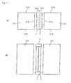
- Figure 1 is a schematic view illustrating one mode of the indirect internal reforming-type solid oxide fuel cell of the present invention.
- Figure 1(a) is a top view and
- Figure 1(b) is a side view.
- a plurality of reaction tubes 2 are arranged in a location interposed between two SOFC stacks (a first stack 3-1 and a second stack 3-2).
- the stacks 3-1 and 3-2 are each a stack in which a plurality of cells of a planar SOFC are laminated.
- Each reaction tube is filled with a reforming catalyst capable of reforming kerosene.
- Each reaction tube is connected to headers 1 at the upper end and the lower end of the tube.
- the reaction tubes and the headers constitute a reformer.
- the headers can suitably employ a well-known header structure in which a gas can be distributed to a plurality of tubes and the gas can be collected from the plurality of tubes.
- reaction tubes circular tubes having the same diameter and length are used. This is preferable in view of the uniformity of the reaction of every reaction tube.
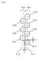
- reaction tubes are arranged in two rows with the tubes spaced from each other and form a staggered arrangement. The way of the reaction tube arrangement will be described using Figure 2 .
- reaction tubes 2-11 to 2-14 are lined up in even intervals in a row to make a first tube row 10-1.
- Reaction tubes 2-21 to 2-23 are also lined up in even intervals in a row to make a second tube row 10-2 parallel with the first row.
- the intervals between the reaction tubes of the first tube row are the same as those between the reaction tubes of the second tube row. This is preferable in view of uniform heat receiving of every reaction tube.
- the two tube rows are arranged in a staggered manner. That is, in the longitudinal direction of the tube rows (in Figure 2 , in the top and down directions on paper), one reaction tube of one tube row is arranged at the middle point of two reaction tubes of the other tube row adjacent to the one tube row.
- the central axis of the reaction tube 2-21 is at equal distances from the central axis of the reaction tube 2-11 and the central axis of the reaction tube 2-12.
- the central axes of the reaction tubes 2-11 to 2-14 are on one plane (a first plane 11-1) and the central axes of the reaction tubes 2-21 to 2-23 are on one plane (a second plane 11-2) different from the first plane.
- the distance between the first plane and the second plane is smaller than the outer diameter of the reaction tubes. Therefore, when viewed from the longitudinal direction of the tube rows, the first row and the second row are overlapped with an overlapping margin ta. That is, the two rows are arranged with an overlap in the direction perpendicular to the tube row direction. Further, the intervals of the reaction tubes in each of the first row and the second row (for example, a distance between the reaction tubes 2-11 and 2-12) are smaller than the outer diameter of the reaction tubes.
- a reaction tube of the first row and a reaction tube of the second row are overlapped with an overlapping margin tb. That is, the two tube rows are arranged with an overlap in the tube row direction.
- arrangement of the tube rows with overlaps is preferable in view of the space utilization efficiency.
- the reaction tubes are arranged inside the flush planes. That is, the lengths of the tube rows of the reaction tubes are smaller than the widths of the stack side surfaces 3-1c and 3-2c, which the reaction tube rows face. Further, the lengths of the tube rows are made near to the widths of the stack side surfaces 3-1c and 3-2c. This is preferable in view of effective heating of the reaction tubes by radiation heat from SOFC.
- each reaction tube and the stack (for the first tube row 10-1, the distance between the tubes thereof and the side surface 3-1 c of the first stack; for the second tube row 10-2, the distance between the tubes thereof and the side surface 3-2c of the second stack) are the same. This is preferable in view of uniform heat receiving of every reaction tube.
- Use of the plurality of reaction tubes allows taking a larger heat receiving area which receives radiation heat and can thereby utilize the radiation heat of an SOFC more effectively compared with use of a single reaction vessel.
- reaction tubes of each of the first tube row and the second tube row are heated by radiation heat from the stacks on both sides. Additionally, since the reaction tubes can be arranged in a shape resembling the so-called closest packing, excellent space utilization efficiency can easily be achieved. Compared with the case where reaction tubes are arranged in a single row, a larger number of reaction tubes can be arranged without making the tube row length long. This is effective on enlarging the heat receiving area. In the case where reaction tubes are arrayed in three or more rows, inner tube row(s) can hardly receive the radiation heat from stacks compared with the end tube rows.
- the reaction tubes are arranged in a location where the radiation heat can be transferred from the stacks to the reaction tubes. This radiation heat is preferably directly transferred. Therefore, preferably, substantially no blocking object is arranged between the reaction tubes and the stacks. Further, the distance between the reaction tubes and the stacks is preferably as short as possible.
- the reaction tube may be of single tube type or double tube type.
- the reaction tube of double tube type has a double tube structure composed of an outer tube and an inner tube, and a reforming catalyst capable of steam-reforming kerosene is packed in the space between the outer tube and the inner tube.
- Figure 1 shows an example in which reaction tube rows are arranged between two stacks
- three or more stacks may be arranged.
- three stacks are lined up in one row; and between the first stack and the second stack and between the second stack and the third stack, corresponding two reaction tube rows may be arranged in a staggered manner.
- the constitution shown in Figure 1 may be lined up adjacently in a plural number.
- Use of a plurality of stacks has an advantage for raising the generated power amount, and enables heating reaction tubes from both sides, and is effective for heating the reaction tubes by radiation heat.
- SOFC stacks well-known SOFC stacks or SOFC bundles of planar type or tubular type may suitably be selected and employed.
- tubular SOFC bundles if a reformer is put in the location interposed between SOFC bundles, the similar effect can be expected.
- SOFC stack is a notion including a bundle into which a plurality of tubular SOFCs is assembled in one bundle.
- An SOFC and a reformer may be contained in a vessel such as a can to make a module.
- a reformed gas which is a hydrogen-containing gas
- kerosene which is a reforming raw material
- steam reforming reaction a partial oxidation reforming reaction may be involved, but the steam reforming is preferably made dominant in view of efficiently manufacturing hydrogen.
- reaction which is endothermic overall progresses in the reformer.
- the partial oxidation reforming reaction is an exothermic reaction and the steam reforming reaction is an endothermic reaction.
- a reforming raw material is C n H 2n+2 (n is a natural number)
- the partial oxidation reforming reaction is represented by C n H 2n+2 + (n/2) O 2 ⁇ n CO + (n+1) H 2
- the steam reforming reaction is represented by C n H 2n+2 + nH 2 O ⁇ n CO + (2n+1) H 2 .
- Usable reforming catalysts capable of steam-reforming kerosene include a steam reforming catalyst and an autothermal reforming catalyst (a catalyst having a steam reforming capability and a partial oxidation reforming capability). In addition to these, a partial oxidation reforming catalyst may be used.
- a reforming catalyst preferably includes a reforming catalyst having a kerosene oxidative activity.
- the kerosene oxidative activity means a capability of generating heat by the oxidation reaction of kerosene with oxygen on a catalyst. With reaction tubes packed with a catalyst having the kerosene oxidative activity, heat is directly generated on the catalyst and a time till the temperature of the reforming catalyst reaches a temperature suitable for reforming can be shortened upon starting-up.
- the reforming catalyst having an oxidative activity for kerosene includes a rhodium-based catalyst.
- a reforming catalyst can be imparted the kerosene oxidative activity by mixing a steam reforming catalyst with a rhodium-based catalyst.
- any well-known catalysts of steam reforming catalysts, autothermal reforming catalysts and partial oxidation reforming catalysts capable of reforming kerosene can suitably be selected and used.
- the partial oxidation reforming catalyst include a platinum-based catalyst
- examples of the steam reforming catalyst include a ruthenium-based catalyst and a nickel-based catalyst
- examples of the autothermal reforming catalyst include a rhodium-based catalyst.
- nickel, noble metals such as platinum, rhodium and ruthenium, and the like are known to have these activities as described in Japanese Patent Laid-Open Nos.
- the reaction temperature of the steam reforming is, for example, in the range of from 450°C to 900°C, preferably from 500°C to 850°C, more preferably from 550°C to 800°C.
- the amount of steam introduced in the reaction system is defined as a ratio (steam/carbon ratio) of the molar number of water molecules to the molar number of carbon atoms contained in a reforming raw material, and this value is set at preferably from 0.5 to 10, more preferably from 1 to 7, still more preferably from 2 to 5.
- the space velocity (LHSV) at this time is represented by A/B where the flow rate of the reforming raw material in the liquid state is A (L/h) and the catalyst layer volume is B (L), and this value is set in the range of preferably from 0.05 to 20 h -1 , more preferably from 0.1 to 10 h -1 , still more preferably from 0.2 to 5 h -1 .
- an oxygen-containing gas is added to a raw material in addition to steam.
- the oxygen-containing gas may be pure oxygen, but is preferably air in view of easy availability.
- the oxygen-containing gas may be added so as to provide a generated heat amount enough to balance the endothermic reaction involved in the steam reforming reaction, and hold or raise the temperatures of a reforming catalyst layer and an SOFC.
- the amount of an oxygen-containing gas added is set, in terms of a ratio (oxygen/carbon ratio) of the molar number of oxygen molecules to the molar number of carbon atoms contained in a reforming raw material, at preferably from 0.05 to 1, more preferably from 0.1 to 0.75, still more preferably from 0.2 to 0.6.
- the reaction temperature of the autothermal reforming reaction is set in the range of, for example, from 450°C to 900°C, preferably from 500°C to 850°C, more preferably from 550°C to 800°C.
- the space velocity (LHSV) at this time is selected in the range of preferably from 0.1 to 30, more preferably from 0.5 to 20, still more preferably from 1 to 10.
- the amount of steam introduced in the reaction system is set, in terms of steam/carbon ratio, at preferably from 0.3 to 10, more preferably from 0.5 to 5, still more preferably from 1 to 3.
- the temperature of a reforming catalyst layer outlet is set at preferably not less than 580°C, more preferably not less than 620°C, still more preferably not less than 650°C to complete the steam reforming reaction of kerosene. Further, to suppress the thermal degradation of the reforming catalyst, the temperature is preferably not more than 850°C, more preferably not more than 800°C, still more preferably not more than 750°C.
- the operation temperature of a cell is preferably not less than 650°C, more preferably not less than 700°C, still more preferably not less than 750°C.
- a cathode gas is supplied to cathode sides of SOFC stacks 3-1 and 3-2.
- an oxygen-containing gas such as air is used.
- Kerosene vaporized in advance and steam are supplied to a reformer. Specifically, the vaporized kerosene and steam are supplied to a header 1 (inlet side), and are branched from the header to each reaction tube. Kerosene can be vaporized utilizing a well-known means which can vaporize kerosene.
- the kerosene is reformed in the each reaction tube to become a reformed gas and the reformed gas is collected in the header 1 (outlet side) and discharged.
- This reformed gas is branched and supplied to anode sides of the stacks 3-1 and 3-2.
- Hydrogen in the reformed gas electrochemically becomes H 2 O, when a power is generated.
- the heat of the gas discharged from the cathode and the gas discharged from the anode are suitably utilized, and then the gases are discharged out of the system (not shown in the figure).
- a reforming catalyst having a kerosene oxidative activity is used as a reforming catalyst, when the radiation heat of an SOFC cannot be utilized, i.e. upon starting-up or the like, or when a further heating in addition to heating by the radiation heat is intended, the oxidation reaction of kerosene is caused by supplying suitably air or the like to reforming tubes, and the reaction heat thereof can be utilized.
- the indirect internal reforming-type SOFC of the present invention can be utilized for a stationary or mobile power generation system and a cogeneration system.
- the reformer of the present invention can suitably be utilized for the indirect internal reforming-type SOFC.
Landscapes
- Chemical & Material Sciences (AREA)
- Chemical Kinetics & Catalysis (AREA)
- Engineering & Computer Science (AREA)
- General Chemical & Material Sciences (AREA)
- Sustainable Energy (AREA)
- Sustainable Development (AREA)
- Manufacturing & Machinery (AREA)
- Electrochemistry (AREA)
- Life Sciences & Earth Sciences (AREA)
- Organic Chemistry (AREA)
- Health & Medical Sciences (AREA)
- General Health & Medical Sciences (AREA)
- Combustion & Propulsion (AREA)
- Inorganic Chemistry (AREA)
- Fuel Cell (AREA)
- Hydrogen, Water And Hydrids (AREA)
Abstract
Description
- The present invention relates to a solid oxide fuel cell, particularly to an indirect internal reforming-type solid oxide fuel cell having a reformer in the vicinity of the fuel cell. The present invention relates also to a reformer to reform kerosene used for an indirect internal reforming-type solid oxide fuel cell.
- In a solid oxide fuel cell (hereinafter, as the case may be, referred to as SOFC), a reformed gas containing hydrogen made by reforming a reforming raw material such as kerosene is supplied as a fuel to an SOFC.
- Since the operation temperature of the SOFC is high and near to the reforming temperature of a reforming raw material, a so-called indirect internal reforming-type SOFC having a structure in which a reformer is disposed in the vicinity of an SOFC and these are contained in a can is employed in some cases (see Patent Document 1). In the indirect internal reforming-type SOFC, radiation heat from an SOFC can be utilized for reforming.
Patent Document 1: Japanese Patent Laid-Open No.2002-358997 - However, when a higher-order hydrocarbon such as kerosene is used as a reforming raw material, if hydrocarbon components whose reforming has not progressed are supplied to a solid oxide fuel cell, whose operation temperature is high, carbon deposition damages the operational stability in some cases. Therefore, a higher-order hydrocarbon such as kerosene is desirably converted completely to a C1 compound (a compound of which carbon number is 1).
- For a reformer to well receive radiation heat from an SOFC, the heat receiving area of the reformer facing the SOFC is desirably made large. If the heat receiving area is small, in some cases, the reformer cannot be well heated by radiation heat from the SOFC and kerosene cannot be completely converted, thereby not enabling the stable operation. In these cases, for not decreasing the conversion ratio of kerosene in a reformer, the fuel utilization ratio is conceivably reduced to increase the amount of waste heat of the SOFC. However, in this method, since the heat by burning a fuel once reformed is utilized for the heat supply to a reformer, the efficiency decreases.
- It is an object of the present invention to provide an indirect internal reforming-type SOFC in which a reformer is heated by radiation heat from an SOFC, wherein the heat receiving area of the reformer can be easily made large and stable operation is possible without decreasing the efficiency.
- It is another object of the present invention to provide a reformer suitably usable for such an indirect internal reforming-type SOFC.
- The present invention provides an indirect internal reforming-type solid oxide fuel cell having a reformer capable of reforming kerosene and a solid oxide fuel cell which uses as a fuel a reformed gas obtained by the reformer, characterized in that:
- the indirect internal reforming-type solid oxide fuel cell has a plurality of solid oxide fuel cell stacks;
- the reformer has a plurality of reaction tubes packed with a reforming catalyst capable of steam-reforming kerosene; and
- the reaction tubes are arranged in two rows with the tubes spaced from each other and form a staggered arrangement in a location interposed between the stacks.
- The two tube rows of the reaction tubes may be arranged with an overlap in the direction perpendicular to the tube row direction.
- The two tube rows of the reaction tubes may be arranged with an overlap in the tube row direction.
- The reforming catalyst preferably includes a reforming catalyst having a kerosene oxidative activity.
- The present invention provides a reformer capable of reforming kerosene, characterized in that:
- the reformer has a plurality of reaction tubes packed with a reforming catalyst; and
- the reaction tubes are arranged in two rows with the tubes spaced from each other and form a staggered arrangement.
- The reforming catalyst preferably includes a reforming catalyst having a kerosene oxidative activity.
- The present invention provides an indirect internal reforming-type SOFC in which a reformer is heated by radiation heat from an SOFC, wherein the heat receiving area of the reformer can be easily made large and stable operation is possible without decreasing the efficiency.
- The present invention provides a reformer suitably usable for such an indirect internal reforming-type SOFC.
-
-
Figure 1 is a schematic view illustrating one mode of the indirect internal reforming-type solid oxide fuel cell of the present invention; and (a) is a top view and (b) is a side view; -
Figure 2 is a schematic view illustrating the arrangement of reaction tubes; and -
Figure 3 is a schematic view illustrating an operation method of the indirect internal reforming-type solid oxide fuel cell of the present invention. -
- 1 HEADER
- 2 REACTION TUBE
- 3 SOLID OXIDE FUEL CELL STACK
- 10 TUBE ROW OF REACTION TUBES
- 11 PLANE CONTAINING CENTER AXES OF REACTION TUBES
- Hereinafter, the present invention will be described in detail by way of the drawings, but the present invention is not limited thereto.
-
Figure 1 is a schematic view illustrating one mode of the indirect internal reforming-type solid oxide fuel cell of the present invention.Figure 1(a) is a top view andFigure 1(b) is a side view. As shown inFigure 1 , a plurality ofreaction tubes 2 are arranged in a location interposed between two SOFC stacks (a first stack 3-1 and a second stack 3-2). - The stacks 3-1 and 3-2 are each a stack in which a plurality of cells of a planar SOFC are laminated.
- Each reaction tube is filled with a reforming catalyst capable of reforming kerosene. Each reaction tube is connected to
headers 1 at the upper end and the lower end of the tube. The reaction tubes and the headers constitute a reformer. The headers can suitably employ a well-known header structure in which a gas can be distributed to a plurality of tubes and the gas can be collected from the plurality of tubes. - As the plurality of reaction tubes, circular tubes having the same diameter and length are used. This is preferable in view of the uniformity of the reaction of every reaction tube.
- The reaction tubes are arranged in two rows with the tubes spaced from each other and form a staggered arrangement. The way of the reaction tube arrangement will be described using
Figure 2 . - As shown in
Figure 2 , reaction tubes 2-11 to 2-14 are lined up in even intervals in a row to make a first tube row 10-1. Reaction tubes 2-21 to 2-23 are also lined up in even intervals in a row to make a second tube row 10-2 parallel with the first row. The intervals between the reaction tubes of the first tube row are the same as those between the reaction tubes of the second tube row. This is preferable in view of uniform heat receiving of every reaction tube. - The two tube rows are arranged in a staggered manner. That is, in the longitudinal direction of the tube rows (in
Figure 2 , in the top and down directions on paper), one reaction tube of one tube row is arranged at the middle point of two reaction tubes of the other tube row adjacent to the one tube row. For example, the central axis of the reaction tube 2-21 is at equal distances from the central axis of the reaction tube 2-11 and the central axis of the reaction tube 2-12. - The central axes of the reaction tubes 2-11 to 2-14 are on one plane (a first plane 11-1) and the central axes of the reaction tubes 2-21 to 2-23 are on one plane (a second plane 11-2) different from the first plane. The distance between the first plane and the second plane is smaller than the outer diameter of the reaction tubes. Therefore, when viewed from the longitudinal direction of the tube rows, the first row and the second row are overlapped with an overlapping margin ta. That is, the two rows are arranged with an overlap in the direction perpendicular to the tube row direction. Further, the intervals of the reaction tubes in each of the first row and the second row (for example, a distance between the reaction tubes 2-11 and 2-12) are smaller than the outer diameter of the reaction tubes. Therefore, when viewed from the lateral direction of the tube rows, a reaction tube of the first row and a reaction tube of the second row (for example, the reaction tubes 2-11 and 2-21) are overlapped with an overlapping margin tb. That is, the two tube rows are arranged with an overlap in the tube row direction. With respect to the overlapping margins ta and tb, arrangement of the tube rows with overlaps is preferable in view of the space utilization efficiency.
- In two SOFC stacks, unit cells of the same shape and size are stacked in the same number of unit cells. Therefore, the two stacks have the nearly same shape and size. The two stacks are lined up so that their side surfaces (side surfaces 3-1 a and 3-2a, and side surfaces 3-1 b and 3-2b) are aligned in a plane.
- The reaction tubes are arranged inside the flush planes. That is, the lengths of the tube rows of the reaction tubes are smaller than the widths of the stack side surfaces 3-1c and 3-2c, which the reaction tube rows face. Further, the lengths of the tube rows are made near to the widths of the stack side surfaces 3-1c and 3-2c. This is preferable in view of effective heating of the reaction tubes by radiation heat from SOFC.
- The distances between each reaction tube and the stack (for the first tube row 10-1, the distance between the tubes thereof and the side surface 3-1 c of the first stack; for the second tube row 10-2, the distance between the tubes thereof and the side surface 3-2c of the second stack) are the same. This is preferable in view of uniform heat receiving of every reaction tube.
- Use of the plurality of reaction tubes allows taking a larger heat receiving area which receives radiation heat and can thereby utilize the radiation heat of an SOFC more effectively compared with use of a single reaction vessel.
- By arranging the reaction tubes in two rows with the tubes spaced from each other and in a staggered manner in the location interposed between the stacks, the reaction tubes of each of the first tube row and the second tube row are heated by radiation heat from the stacks on both sides. Additionally, since the reaction tubes can be arranged in a shape resembling the so-called closest packing, excellent space utilization efficiency can easily be achieved.
Compared with the case where reaction tubes are arranged in a single row, a larger number of reaction tubes can be arranged without making the tube row length long. This is effective on enlarging the heat receiving area. In the case where reaction tubes are arrayed in three or more rows, inner tube row(s) can hardly receive the radiation heat from stacks compared with the end tube rows. Hence, effective usage of the surface area of reaction tubes as a heat receiving area becomes difficult, and the heat amount which every reaction tube receives becomes nonuniform. By making tube rows in two rows, it is easy to avoid such a situation, to use the surface of the reaction tubes as an effective heat receiving area, and to easily achieve an excellent uniformity of the heat amount which every reaction tube receives. - The reaction tubes are arranged in a location where the radiation heat can be transferred from the stacks to the reaction tubes. This radiation heat is preferably directly transferred. Therefore, preferably, substantially no blocking object is arranged between the reaction tubes and the stacks. Further, the distance between the reaction tubes and the stacks is preferably as short as possible.
- The reaction tube may be of single tube type or double tube type. The reaction tube of double tube type has a double tube structure composed of an outer tube and an inner tube, and a reforming catalyst capable of steam-reforming kerosene is packed in the space between the outer tube and the inner tube.
- Although
Figure 1 shows an example in which reaction tube rows are arranged between two stacks, three or more stacks may be arranged. For example, three stacks are lined up in one row; and between the first stack and the second stack and between the second stack and the third stack, corresponding two reaction tube rows may be arranged in a staggered manner. Further, the constitution shown inFigure 1 may be lined up adjacently in a plural number. Use of a plurality of stacks has an advantage for raising the generated power amount, and enables heating reaction tubes from both sides, and is effective for heating the reaction tubes by radiation heat. - As SOFC stacks, well-known SOFC stacks or SOFC bundles of planar type or tubular type may suitably be selected and employed. In the case of tubular SOFC bundles, if a reformer is put in the location interposed between SOFC bundles, the similar effect can be expected. In the present invention, "SOFC stack" is a notion including a bundle into which a plurality of tubular SOFCs is assembled in one bundle.
- An SOFC and a reformer may be contained in a vessel such as a can to make a module.
- In a reformer, especially in reaction tubes, a reformed gas, which is a hydrogen-containing gas, is manufactured from kerosene, which is a reforming raw material, by the steam reforming reaction. At this time, a partial oxidation reforming reaction may be involved, but the steam reforming is preferably made dominant in view of efficiently manufacturing hydrogen. At this time, reaction which is endothermic overall progresses in the reformer.
- The partial oxidation reforming reaction is an exothermic reaction and the steam reforming reaction is an endothermic reaction. When a reforming raw material is CnH2n+2 (n is a natural number), the partial oxidation reforming reaction is represented by CnH2n+2 + (n/2) O2 → n CO + (n+1) H2. The steam reforming reaction is represented by CnH2n+2 + nH2O → n CO + (2n+1) H2.
- Usable reforming catalysts capable of steam-reforming kerosene include a steam reforming catalyst and an autothermal reforming catalyst (a catalyst having a steam reforming capability and a partial oxidation reforming capability). In addition to these, a partial oxidation reforming catalyst may be used.
- A reforming catalyst preferably includes a reforming catalyst having a kerosene oxidative activity. The kerosene oxidative activity means a capability of generating heat by the oxidation reaction of kerosene with oxygen on a catalyst. With reaction tubes packed with a catalyst having the kerosene oxidative activity, heat is directly generated on the catalyst and a time till the temperature of the reforming catalyst reaches a temperature suitable for reforming can be shortened upon starting-up. The reforming catalyst having an oxidative activity for kerosene includes a rhodium-based catalyst. For example, a reforming catalyst can be imparted the kerosene oxidative activity by mixing a steam reforming catalyst with a rhodium-based catalyst.
- Any well-known catalysts of steam reforming catalysts, autothermal reforming catalysts and partial oxidation reforming catalysts capable of reforming kerosene can suitably be selected and used. Examples of the partial oxidation reforming catalyst include a platinum-based catalyst; examples of the steam reforming catalyst include a ruthenium-based catalyst and a nickel-based catalyst; and examples of the autothermal reforming catalyst include a rhodium-based catalyst. With respect to the autothermal reforming catalyst, nickel, noble metals such as platinum, rhodium and ruthenium, and the like are known to have these activities as described in Japanese Patent Laid-Open Nos.
2000-84410 2001-80907 U.S. Patent No 5,929,286 . Conventionally well-known catalyst shapes of a pellet form, a honeycomb form and other forms can suitably be employed. - Hereinafter, the respective operation conditions during power generation of the steam reforming and the autothermal reforming will be described.
- The reaction temperature of the steam reforming is, for example, in the range of from 450°C to 900°C, preferably from 500°C to 850°C, more preferably from 550°C to 800°C. The amount of steam introduced in the reaction system is defined as a ratio (steam/carbon ratio) of the molar number of water molecules to the molar number of carbon atoms contained in a reforming raw material, and this value is set at preferably from 0.5 to 10, more preferably from 1 to 7, still more preferably from 2 to 5. If the reforming raw material is a liquid, the space velocity (LHSV) at this time is represented by A/B where the flow rate of the reforming raw material in the liquid state is A (L/h) and the catalyst layer volume is B (L), and this value is set in the range of preferably from 0.05 to 20 h-1, more preferably from 0.1 to 10 h-1, still more preferably from 0.2 to 5 h-1.
- In the autothermal reforming, an oxygen-containing gas is added to a raw material in addition to steam. The oxygen-containing gas may be pure oxygen, but is preferably air in view of easy availability. The oxygen-containing gas may be added so as to provide a generated heat amount enough to balance the endothermic reaction involved in the steam reforming reaction, and hold or raise the temperatures of a reforming catalyst layer and an SOFC. The amount of an oxygen-containing gas added is set, in terms of a ratio (oxygen/carbon ratio) of the molar number of oxygen molecules to the molar number of carbon atoms contained in a reforming raw material, at preferably from 0.05 to 1, more preferably from 0.1 to 0.75, still more preferably from 0.2 to 0.6. The reaction temperature of the autothermal reforming reaction is set in the range of, for example, from 450°C to 900°C, preferably from 500°C to 850°C, more preferably from 550°C to 800°C. If the raw material is a liquid, the space velocity (LHSV) at this time is selected in the range of preferably from 0.1 to 30, more preferably from 0.5 to 20, still more preferably from 1 to 10. The amount of steam introduced in the reaction system is set, in terms of steam/carbon ratio, at preferably from 0.3 to 10, more preferably from 0.5 to 5, still more preferably from 1 to 3.
- The temperature of a reforming catalyst layer outlet is set at preferably not less than 580°C, more preferably not less than 620°C, still more preferably not less than 650°C to complete the steam reforming reaction of kerosene. Further, to suppress the thermal degradation of the reforming catalyst, the temperature is preferably not more than 850°C, more preferably not more than 800°C, still more preferably not more than 750°C.
- From the view point that a sufficient heat is given to the reforming reaction described above by an SOFC, the operation temperature of a cell is preferably not less than 650°C, more preferably not less than 700°C, still more preferably not less than 750°C.
- A method for operating the indirect internal reforming-type SOFC of the present invention will be described. As shown in
Figure 3 , a cathode gas is supplied to cathode sides of SOFC stacks 3-1 and 3-2. As the cathode gas, an oxygen-containing gas such as air is used. Kerosene vaporized in advance and steam are supplied to a reformer. Specifically, the vaporized kerosene and steam are supplied to a header 1 (inlet side), and are branched from the header to each reaction tube. Kerosene can be vaporized utilizing a well-known means which can vaporize kerosene. - The kerosene is reformed in the each reaction tube to become a reformed gas and the reformed gas is collected in the header 1 (outlet side) and discharged. This reformed gas is branched and supplied to anode sides of the stacks 3-1 and 3-2. Hydrogen in the reformed gas electrochemically becomes H2O, when a power is generated. The heat of the gas discharged from the cathode and the gas discharged from the anode are suitably utilized, and then the gases are discharged out of the system (not shown in the figure).
- If a reforming catalyst having a kerosene oxidative activity is used as a reforming catalyst, when the radiation heat of an SOFC cannot be utilized, i.e. upon starting-up or the like, or when a further heating in addition to heating by the radiation heat is intended, the oxidation reaction of kerosene is caused by supplying suitably air or the like to reforming tubes, and the reaction heat thereof can be utilized.
- The indirect internal reforming-type SOFC of the present invention can be utilized for a stationary or mobile power generation system and a cogeneration system. The reformer of the present invention can suitably be utilized for the indirect internal reforming-type SOFC.
Claims (7)
- An indirect internal reforming-type solid oxide fuel cell comprising a reformer capable of reforming kerosene and a solid oxide fuel cell which uses as a fuel a reformed gas obtained by the reformer, characterized in that:the indirect internal reforming-type solid oxide fuel cell comprises a plurality of solid oxide fuel cell stacks;the reformer comprises a plurality of reaction tubes packed with a reforming catalyst capable of steam-reforming kerosene; andthe reaction tubes are arranged in two rows with the tubes spaced from each other and form a staggered arrangement in a location interposed between the stacks.
- The indirect internal reforming-type solid oxide fuel cell according to claim 1, wherein the two tube rows of the reaction tubes are arranged with an overlap in the direction perpendicular to the tube row direction.
- The indirect internal reforming-type solid oxide fuel cell according to claim 1 or 2, wherein the two tube rows of the reaction tubes are arranged with an overlap in the tube row direction.
- The indirect internal reforming-type solid oxide fuel cell according to claim 1 or 2, wherein the reforming catalyst comprises a reforming catalyst having a kerosene oxidative activity.
- The indirect internal reforming-type solid oxide fuel cell according to claim 3, wherein the reforming catalyst comprises a reforming catalyst having a kerosene oxidative activity.
- A reformer capable of reforming kerosene, used for an indirect internal reforming-type solid oxide fuel cell, characterized in that:the reformer has a plurality of reaction tubes packed with a reforming catalyst; andthe reaction tubes are arranged in two rows with the tubes spaced from each other and form a staggered arrangement.
- The reformer according to claim 6, wherein the reforming catalyst comprises a reforming catalyst having a kerosene oxidative activity.
Applications Claiming Priority (2)
| Application Number | Priority Date | Filing Date | Title |
|---|---|---|---|
| JP2006098636A JP5224651B2 (en) | 2006-03-31 | 2006-03-31 | Solid oxide fuel cell |
| PCT/JP2007/056281 WO2007114110A1 (en) | 2006-03-31 | 2007-03-27 | Solid oxide fuel cell and reformer |
Publications (2)
| Publication Number | Publication Date |
|---|---|
| EP2009726A1 true EP2009726A1 (en) | 2008-12-31 |
| EP2009726A4 EP2009726A4 (en) | 2009-12-02 |
Family
ID=38563379
Family Applications (1)
| Application Number | Title | Priority Date | Filing Date |
|---|---|---|---|
| EP07739719A Withdrawn EP2009726A4 (en) | 2006-03-31 | 2007-03-27 | Solid oxide fuel cell and reformer |
Country Status (8)
| Country | Link |
|---|---|
| US (1) | US20090117424A1 (en) |
| EP (1) | EP2009726A4 (en) |
| JP (1) | JP5224651B2 (en) |
| KR (1) | KR101350127B1 (en) |
| CN (1) | CN101427413B (en) |
| CA (1) | CA2647797C (en) |
| TW (1) | TWI412171B (en) |
| WO (1) | WO2007114110A1 (en) |
Families Citing this family (8)
| Publication number | Priority date | Publication date | Assignee | Title |
|---|---|---|---|---|
| JP5266122B2 (en) * | 2009-03-30 | 2013-08-21 | Jx日鉱日石エネルギー株式会社 | Oxidation autothermal reformer and fuel cell system |
| JP5266123B2 (en) * | 2009-03-30 | 2013-08-21 | Jx日鉱日石エネルギー株式会社 | Oxidation autothermal reformer and fuel cell system |
| CN102365779B (en) * | 2009-04-08 | 2013-04-17 | 吉坤日矿日石能源株式会社 | Method of stopping indirect internal reforming solid oxide fuel cell |
| JP5561655B2 (en) * | 2010-09-30 | 2014-07-30 | Toto株式会社 | Solid oxide fuel cell device |
| KR101171955B1 (en) | 2011-01-11 | 2012-08-08 | 고려대학교 산학협력단 | Solid Oxide Fuel Cell |
| JP5487187B2 (en) * | 2011-11-16 | 2014-05-07 | 株式会社東芝 | High frequency amplifier |
| JP6194854B2 (en) * | 2013-12-05 | 2017-09-13 | 株式会社デンソー | Fuel cell device |
| CN105253856B (en) * | 2015-10-29 | 2017-04-05 | 中国人民解放军防化学院 | A kind of carbon-based fuel reforming hydrogen production device |
Citations (3)
| Publication number | Priority date | Publication date | Assignee | Title |
|---|---|---|---|---|
| US5733675A (en) * | 1995-08-23 | 1998-03-31 | Westinghouse Electric Corporation | Electrochemical fuel cell generator having an internal and leak tight hydrocarbon fuel reformer |
| JPH10125342A (en) * | 1996-10-17 | 1998-05-15 | Toshiba Corp | Fuel reformer |
| US20050081444A1 (en) * | 2003-10-17 | 2005-04-21 | General Electric Company | Catalytic partial oxidation processor with heat exchanger for converting hydrocarbon fuels to syngas for use in fuel cells and method |
Family Cites Families (26)
| Publication number | Priority date | Publication date | Assignee | Title |
|---|---|---|---|---|
| US3785953A (en) * | 1971-11-09 | 1974-01-15 | Antar Petroles Atlantique | Process for carrying out endothermic catalytic reactions |
| US4522894A (en) * | 1982-09-30 | 1985-06-11 | Engelhard Corporation | Fuel cell electric power production |
| JPH02124701A (en) * | 1988-11-01 | 1990-05-14 | Toshiba Corp | Shell-and-tube reformer |
| EP0398111A1 (en) * | 1989-05-18 | 1990-11-22 | Asea Brown Boveri Ag | Device for converting chemical energy of hydrocarbons to electrical energy by means of electrochemical high temperature process |
| JPH0455302A (en) * | 1990-06-20 | 1992-02-24 | Tokyo Electric Power Co Inc:The | Hydrocarbon reformer |
| JP3069743B2 (en) * | 1990-10-09 | 2000-07-24 | 溶融炭酸塩型燃料電池発電システム技術研究組合 | Two-stage catalytic combustion reformer for fuel cells |
| JPH07272741A (en) * | 1994-03-31 | 1995-10-20 | Mitsubishi Heavy Ind Ltd | Module structure for cylindrical solid electrolytic fuel cell |
| US6110861A (en) | 1997-06-02 | 2000-08-29 | The University Of Chicago | Partial oxidation catalyst |
| JP4041567B2 (en) * | 1997-12-25 | 2008-01-30 | 千代田化工建設株式会社 | Catalytic reforming reactor |
| JP2000084410A (en) | 1998-07-14 | 2000-03-28 | Idemitsu Kosan Co Ltd | Preparation of autothermal reforming catalyst and production of hydrogen or synthesis gas |
| JP4326078B2 (en) * | 1999-07-29 | 2009-09-02 | 三菱重工業株式会社 | Solid oxide fuel cell module |
| EP1077198A3 (en) | 1999-08-19 | 2001-03-07 | Haldor Topsoe A/S | Process for pre-reforming of oxygen-containing gas |
| JP3539562B2 (en) * | 2001-05-31 | 2004-07-07 | 日本電信電話株式会社 | Solid oxide fuel cell stack |
| WO2002103833A1 (en) * | 2001-06-15 | 2002-12-27 | Ztek Corporation | Zero/low emission and co-production energy supply station |
| JP2003115307A (en) * | 2001-10-05 | 2003-04-18 | Nippon Steel Corp | Interior reformer of solid electrolyte-type fuel cell |
| JP3917838B2 (en) * | 2001-10-12 | 2007-05-23 | 三菱重工業株式会社 | Fuel cell system and combined power generation system |
| JP2003123824A (en) * | 2001-10-16 | 2003-04-25 | Shin Etsu Chem Co Ltd | Fuel cell system |
| JP2003277005A (en) * | 2002-03-19 | 2003-10-02 | Hitachi Ltd | Hydrogen manufacturing apparatus, system for generating electricity by using the same, and method for operating the same |
| JP2003327411A (en) * | 2002-05-10 | 2003-11-19 | Yokohama Tlo Co Ltd | Apparatus and method for reforming fuel for fuel cell |
| EP1526166A4 (en) * | 2002-07-22 | 2007-10-10 | Idemitsu Kosan Co | Method for desulfurization of liquid hydrocarbons and process for production of hydrogen for fuel cells |
| JP2004137116A (en) * | 2002-10-18 | 2004-05-13 | Mitsubishi Heavy Ind Ltd | Reformer |
| JP4163657B2 (en) * | 2003-05-16 | 2008-10-08 | 本田技研工業株式会社 | Fuel reformer |
| WO2005001980A1 (en) * | 2003-06-30 | 2005-01-06 | Japan Energy Corporation | Fuel cell with reformer |
| JP2005044651A (en) * | 2003-07-23 | 2005-02-17 | Nissan Motor Co Ltd | Method of manufacturing hydrogen rich gas |
| JP4477432B2 (en) * | 2004-06-29 | 2010-06-09 | 東洋エンジニアリング株式会社 | Reformer |
| US20060147771A1 (en) * | 2005-01-04 | 2006-07-06 | Ion America Corporation | Fuel cell system with independent reformer temperature control |
-
2006
- 2006-03-31 JP JP2006098636A patent/JP5224651B2/en not_active Expired - Fee Related
-
2007
- 2007-03-27 EP EP07739719A patent/EP2009726A4/en not_active Withdrawn
- 2007-03-27 US US12/295,483 patent/US20090117424A1/en not_active Abandoned
- 2007-03-27 CA CA2647797A patent/CA2647797C/en not_active Expired - Fee Related
- 2007-03-27 KR KR1020087025125A patent/KR101350127B1/en not_active IP Right Cessation
- 2007-03-27 CN CN2007800109267A patent/CN101427413B/en active Active
- 2007-03-27 WO PCT/JP2007/056281 patent/WO2007114110A1/en active Application Filing
- 2007-03-28 TW TW096110740A patent/TWI412171B/en not_active IP Right Cessation
Patent Citations (3)
| Publication number | Priority date | Publication date | Assignee | Title |
|---|---|---|---|---|
| US5733675A (en) * | 1995-08-23 | 1998-03-31 | Westinghouse Electric Corporation | Electrochemical fuel cell generator having an internal and leak tight hydrocarbon fuel reformer |
| JPH10125342A (en) * | 1996-10-17 | 1998-05-15 | Toshiba Corp | Fuel reformer |
| US20050081444A1 (en) * | 2003-10-17 | 2005-04-21 | General Electric Company | Catalytic partial oxidation processor with heat exchanger for converting hydrocarbon fuels to syngas for use in fuel cells and method |
Non-Patent Citations (1)
| Title |
|---|
| See also references of WO2007114110A1 * |
Also Published As
| Publication number | Publication date |
|---|---|
| TW200810226A (en) | 2008-02-16 |
| CN101427413B (en) | 2011-11-09 |
| KR101350127B1 (en) | 2014-01-09 |
| CN101427413A (en) | 2009-05-06 |
| TWI412171B (en) | 2013-10-11 |
| JP2007273317A (en) | 2007-10-18 |
| EP2009726A4 (en) | 2009-12-02 |
| KR20090004972A (en) | 2009-01-12 |
| WO2007114110A1 (en) | 2007-10-11 |
| JP5224651B2 (en) | 2013-07-03 |
| US20090117424A1 (en) | 2009-05-07 |
| CA2647797C (en) | 2014-02-04 |
| CA2647797A1 (en) | 2007-10-11 |
Similar Documents
| Publication | Publication Date | Title |
|---|---|---|
| CA2647797C (en) | Solid oxide fuel cell and reformer | |
| JP4056770B2 (en) | Solid oxide fuel cell system | |
| EP2331247B1 (en) | Reformer | |
| EP2273594A1 (en) | Reformer, cell stack device, fuel cell module, and fuel cell device | |
| JP2006012817A (en) | Reformer for fuel cell and fuel cell system comprising the same | |
| JP2007128716A (en) | Fuel cell | |
| EP2772465B1 (en) | Hydrodesulfurization device, hydrogen generation device, and fuel cell system | |
| JP5606165B2 (en) | Cell stack device, fuel cell module and fuel cell device | |
| JP2010277746A (en) | Cell stack device and fuel cell module, and fuel cell device | |
| US20050271907A1 (en) | Reformer and fuel cell system having the same | |
| US6602626B1 (en) | Fuel cell with internal thermally integrated autothermal reformer | |
| US20200168935A1 (en) | Solid oxide fuel cell system configured for higher hydrocarbon fuels | |
| US20100143755A1 (en) | Multi-Channel Fuel Reformer with Augmented Heat Transfer | |
| JP5317756B2 (en) | Reformer, cell stack device, fuel cell module, and fuel cell device | |
| JPH06325783A (en) | Internal reforming type fused carbonate type fuel cell system | |
| JP5977143B2 (en) | Fuel cell module | |
| KR101422630B1 (en) | Heat exchange type prereformer | |
| JP2009129701A (en) | Fuel cell module | |
| JP5584022B2 (en) | Fuel cell system and starting method thereof | |
| JP2009091181A (en) | Reforming apparatus and fuel cell system | |
| JP5552379B2 (en) | Power generator | |
| KR100905422B1 (en) | Fuel Reformer And Manufacturing Method thereof | |
| JP2008226705A (en) | Fuel reformer and fuel cell | |
| JP2008230929A (en) | Chemical reaction apparatus, apparatus for generating hydrogen, and fuel cell system | |
| KR100804693B1 (en) | Carbon monoxide reducing device for reformer used in fuel cell, and fuel cell system comprising same |
Legal Events
| Date | Code | Title | Description |
|---|---|---|---|
| PUAI | Public reference made under article 153(3) epc to a published international application that has entered the european phase |
Free format text: ORIGINAL CODE: 0009012 |
|
| 17P | Request for examination filed |
Effective date: 20081001 |
|
| AK | Designated contracting states |
Kind code of ref document: A1 Designated state(s): AT BE BG CH CY CZ DE DK EE ES FI FR GB GR HU IE IS IT LI LT LU LV MC MT NL PL PT RO SE SI SK TR |
|
| AX | Request for extension of the european patent |
Extension state: AL BA HR MK RS |
|
| A4 | Supplementary search report drawn up and despatched |
Effective date: 20091102 |
|
| 17Q | First examination report despatched |
Effective date: 20100311 |
|
| DAX | Request for extension of the european patent (deleted) | ||
| STAA | Information on the status of an ep patent application or granted ep patent |
Free format text: STATUS: THE APPLICATION IS DEEMED TO BE WITHDRAWN |
|
| 18D | Application deemed to be withdrawn |
Effective date: 20150807 |