EP2008946B1 - Behälter für Flüssigkeiten - Google Patents
Behälter für Flüssigkeiten Download PDFInfo
- Publication number
- EP2008946B1 EP2008946B1 EP08154667A EP08154667A EP2008946B1 EP 2008946 B1 EP2008946 B1 EP 2008946B1 EP 08154667 A EP08154667 A EP 08154667A EP 08154667 A EP08154667 A EP 08154667A EP 2008946 B1 EP2008946 B1 EP 2008946B1
- Authority
- EP
- European Patent Office
- Prior art keywords
- electrically conductive
- drainage device
- flange
- liquid container
- container
- Prior art date
- Legal status (The legal status is an assumption and is not a legal conclusion. Google has not performed a legal analysis and makes no representation as to the accuracy of the status listed.)
- Active
Links
Images


Classifications
-
- B—PERFORMING OPERATIONS; TRANSPORTING
- B65—CONVEYING; PACKING; STORING; HANDLING THIN OR FILAMENTARY MATERIAL
- B65D—CONTAINERS FOR STORAGE OR TRANSPORT OF ARTICLES OR MATERIALS, e.g. BAGS, BARRELS, BOTTLES, BOXES, CANS, CARTONS, CRATES, DRUMS, JARS, TANKS, HOPPERS, FORWARDING CONTAINERS; ACCESSORIES, CLOSURES, OR FITTINGS THEREFOR; PACKAGING ELEMENTS; PACKAGES
- B65D25/00—Details of other kinds or types of rigid or semi-rigid containers
- B65D25/38—Devices for discharging contents
- B65D25/40—Nozzles or spouts
- B65D25/42—Integral or attached nozzles or spouts
-
- B—PERFORMING OPERATIONS; TRANSPORTING
- B67—OPENING, CLOSING OR CLEANING BOTTLES, JARS OR SIMILAR CONTAINERS; LIQUID HANDLING
- B67D—DISPENSING, DELIVERING OR TRANSFERRING LIQUIDS, NOT OTHERWISE PROVIDED FOR
- B67D7/00—Apparatus or devices for transferring liquids from bulk storage containers or reservoirs into vehicles or into portable containers, e.g. for retail sale purposes
- B67D7/06—Details or accessories
- B67D7/32—Arrangements of safety or warning devices; Means for preventing unauthorised delivery of liquid
- B67D7/3236—Arrangements of safety or warning devices; Means for preventing unauthorised delivery of liquid relating to electrostatic charges
-
- B—PERFORMING OPERATIONS; TRANSPORTING
- B65—CONVEYING; PACKING; STORING; HANDLING THIN OR FILAMENTARY MATERIAL
- B65D—CONTAINERS FOR STORAGE OR TRANSPORT OF ARTICLES OR MATERIALS, e.g. BAGS, BARRELS, BOTTLES, BOXES, CANS, CARTONS, CRATES, DRUMS, JARS, TANKS, HOPPERS, FORWARDING CONTAINERS; ACCESSORIES, CLOSURES, OR FITTINGS THEREFOR; PACKAGING ELEMENTS; PACKAGES
- B65D2213/00—Safety means
- B65D2213/02—Means for preventing buil-up of electrostatic charges
-
- Y—GENERAL TAGGING OF NEW TECHNOLOGICAL DEVELOPMENTS; GENERAL TAGGING OF CROSS-SECTIONAL TECHNOLOGIES SPANNING OVER SEVERAL SECTIONS OF THE IPC; TECHNICAL SUBJECTS COVERED BY FORMER USPC CROSS-REFERENCE ART COLLECTIONS [XRACs] AND DIGESTS
- Y10—TECHNICAL SUBJECTS COVERED BY FORMER USPC
- Y10T—TECHNICAL SUBJECTS COVERED BY FORMER US CLASSIFICATION
- Y10T29/00—Metal working
- Y10T29/49—Method of mechanical manufacture
- Y10T29/49826—Assembling or joining
- Y10T29/49879—Spaced wall tube or receptacle
Definitions
- the present invention relates to a liquid container in accordance with the preamble of claim 1.
- Liquid containers are known and used, for example, in the chemical industry for the transport and storage of chemicals. When such containers are filled or emptied, electric charges may be generated as a result of friction between the liquid and the container. The presence of electrostatic charges is very dangerous because ignition sources may come into contact with mixtures of highly explosive gases and vapors.
- a container equipped with a system for grounding any liquids contained in the container is disclosed, for example, in US 6,156,969 and US 2003/0111465 .
- US 6,156,969 discloses a transport and storage container for liquids having a pallet-like frame of an electrically conductive material, an inner container of synthetic material with four sidewalls, a top wall and a bottom wall, an inlet opening in the top wall and an outlet opening with a drainage device in one sidewall, and an outer metal grate.
- the container comprises a grounding member of an electrically conductive material, preferably metal, arranged in the passageway of the drainage device between the outlet valve of the drainage device and the inner container to discharge the electric charges that may generate due to liquid friction during the container filling and emptying operations.
- the container is equipped with an externally-mounted electrically conductive connecting element, which comprises a grounding connection to the underframe of the container.
- US 2003/111465 discloses a pallet-like container having a container wall with an outlet opening and a drainage device with a flange.
- the drainage device is connected to the outlet opening of the container and is fixed to the container through the flange.
- the container further comprises a conductive element for discharging electric charges from the container. Particularly, at least one portion of the conductive element is placed between the flange and the container wall.
- the container of US 6,156,969 requires a hole to be formed in the body of the drainage device for the metal grounding connection screw to be inserted from the outside.
- DE 102 16 960 discloses a liquid container wherein one sidewall is equipped with a drain connector made of a plastic material having a tightness surface.
- a metal hose clamp preferably of corrosion-resistant steel, keeps such a tightness surface pressed against a corresponding surface of a plastic drain valve.
- An electrically conductive disc having at least one contact lever projecting inside the drain connector, is placed between the tightness surface and the drain valve and is connected toward the outside in an electrically conductive way with the hose clamp.
- the hose clamp is connected through an electrically conductive connection, in the example a ground lead, with a protection grid.
- the object of the present invention is therefore to provide a liquid container that has such features as to fulfil said need, while overcoming the drawbacks of known art.
- electrically conductive means made of electrically conductive plastic material results in optimal compatibility with the elements the drainage device is connected to, still maintaining high tightness.
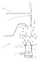
- numeral 1 generally designates a liquid container according to the present invention.
- the liquid container 1 comprises a container body 2 of plastic material with an outlet sleeve 3, a drainage device 10 of plastic material having a flange 11, and electrically conductive means, generally designated by numeral 20, for discharging electrostatic charges from the container 1.
- the container body 2 is formed by extrusion and blow molding from a parison of plastic material, such as polyethylene, particularly high density polyethylene, and has four sidewalls, one of which has a liquid outlet connection, a bottom wall and a top wall with a liquid inlet connection for filling the container.
- plastic material such as polyethylene, particularly high density polyethylene
- the figures only show a portion of the bottom wall 4 and a portion of a sidewall 5 of the container body 2.
- the outlet sleeve 3, which defines the liquid outlet connection of the container 1, is formed at a sidewall, in the example in the lower part of sidewall 5 of the container body 2.
- the drainage device 10 is made of an electrically insulating material, such as polypropylene, polyethylene, etc., eventually reinforced, e.g. with glass fibres.
- the drainage device 10 further comprises a tubular member 12 which is at least partly inserted in the outlet sleeve 3 of the container body 2, from the flange 11.
- the tubular member 12 is totally inserted in the outlet sleeve 3 up to the portion of sidewall 5 from which the outlet sleeve 3 extends. It shall be noted that the tubular member 12 may also be inserted in the outlet sleeve 3 beyond sidewall 5 to at least partly penetrate the container body 2.
- the electrically conductive means 20 comprise a first portion 21 interposed between the tubular member 12 of the drainage device 10 and the outlet sleeve 3 of the container body 2 and a second portion 22, electrically connected to the first portion 21, and placed between the flange 11 of the drainage device 10 and the free end 3a of the outlet sleeve 3.
- the second portion 22 projects out of the drainage device 10.
- the first portion 21 is in contact with the liquid stored within the container body 2, and the second portion 22, connected to the first portion 21 and projecting out of the drainage device 10, allows for the connection with an earth mass, such as for example an earth mass 30 as shown in the figures.
- an earth mass such as for example an earth mass 30 as shown in the figures.
- the electrically conductive means are made of an electrically conductive plastic material. This increases compatibility with the plastic materials the electrically conductive means are connected to, while maintaining a high tightness of the drainage device.
- the electrically conductive plastic material is a heat-sealable polymeric material comprising carbon black, stainless steel, nickel, aluminium fibres, copper or combinations thereof. More specifically, the presence of these components within the plastic material matrix results in the heat-sealable polymeric material being conveniently and advantageously conductive.
- Suitable heat-sealable polymeric materials are selected from polyolefins, fluorinated polymers and mixtures thereof.
- said heat-sealable polymeric material is polypropylene or high density polyethylene. More preferably, said electrically conductive plastic material is high density polyethylene (HDPE) comprising carbon black.
- HDPE high density polyethylene
- the first portion 21 is interposed between the outer surface 12a of the tubular member 12 of the drainage device 10 and the inner surface 3b of the outlet sleeve 3 of the container body 2.
- the electrically conductive means 20 comprise a tubular sleeve 21 extending lengthwise in a X-X direction, and at least partly fitting onto the tubular member 12 of the drainage device 10 as defined in claim 1.
- the tubular sleeve 21 is totally fitted onto the tubular member 12 up to the free end 12b opposite the end 12c from which the flange 11 extends.
- the tubular sleeve 21 may be also fitted onto the tubular member 12 and terminate before or after reaching the free end 12b of the tubular member 12 up to at least partly penetrate the container body 2.
- the lengthwise extension along the X-X direction of the tubular sleeve 21 may be smaller or greater than or equal to the lengthwise extension along X-X direction of the tubular member 12.
- the electrically conductive means 20 further comprise a flange 22 which extends transversely of the lengthwise X-X direction and is connected to the tubular sleeve 21.
- the flange 22 of the electrically conductive means 20 is disposed at the end 21a of the tubular sleeve 21 opposite the free end 21b.
- the flange 22 of the electrically conductive means 20 abuts against the flange 11 of the drainage device 10.
- the tubular sleeve 21 and the flange 22 define an electrically conductive element 20 which is welded to the tubular member 12 of the drainage device 10. Welding occurs between the flange 11 and a surface 22a of the electrically conductive element 20, particularly the flange 22.
- the assembly composed of the drainage device 10 and the conductive element 20 is in turn connected to the outlet sleeve 3 as defined in claim 1.
- the connection is carried out by welding the free end 3a of the outlet sleeve 3 with the surface 22b of the conductive element 20, opposite the surface 22a.
- the drainage device 10 further comprises a liquid inlet opening 13 defined by the free end 12b of the tubular member of the drainage device 10.
- the drainage device 10 further comprises a liquid flowing conduit 14, an outlet opening 15 and a shutting valve 16, such as a throttle valve or a ball valve, for shutting off the liquid flowing through said liquid flowing conduit 14 from the inlet opening 13 to the outlet opening.
- a shutting valve 16 such as a throttle valve or a ball valve
- the present invention further relates to a process for manufacturing a liquid container 1 as described above, comprising the steps of:
- the process as described above allows to conveniently and advantageously produce the container of the invention in a rapid and cost-effective way, since it requires only a few simple and extremely rapid steps. Furthermore, the welding allows to fix the different components in an advantageously stable and safe way.
- suitable welding techniques are hot-plate heat sealing, spin welding, ultrasonic welding or vibration welding.
- heat sealing is preferred.
- step b) comprises both heating the surface of the flange 11 of the drainage device 10 facing the tubular member 12, and heating the surface 22a of the flange 22 of the electrically conductive means 20 prior to welding them together; and step c) comprises both heating the surface 22b of the flange 22 of the electrically conductive means 20 and heating the end surface 3a of the outlet sleeve 3 prior to welding them together.
- step b) can be carried out after step c).
- step b) can be carried out after step c).
- step c) because it is easier to weld first the electrically conductive means 20 to the outlet sleeve 3 together.
- the drainage device 10 in its final location, i.e. with the tubular member 12 of the drainage device 10 interference-fitted into the tubular sleeve 21 of the electrically conductive means 20 and therefore abutting against the electrically conductive means 20, it is conveniently possible to exert a pressure on the latter, advantageously along the X-X direction, thereby promoting the welding of the former abut against the latter, This operation allows to weld the electrically conductive means 20 together with the outlet sleeve 3 of the container of the container body 2.
- step a) a container body (2), electrically conductive means (20) and a drainage device (10) are provided in a pre-assembled form.
- liquid container according to the present invention allows to overcome the above-mentioned drawbacks with reference to known art.
- the presence of electrically conductive means made of an electrically conductive plastic material results in optimal compatibility with the elements the drainage device is connected to, while maintaining a high drainage device tightness.
Landscapes
- Engineering & Computer Science (AREA)
- Mechanical Engineering (AREA)
- Details Of Rigid Or Semi-Rigid Containers (AREA)
- Lining Or Joining Of Plastics Or The Like (AREA)
- Devices For Use In Laboratory Experiments (AREA)
Claims (13)
- Flüssigkeitscontainer (1) mit:einem Containerkörper (2) aus Kunststoffmaterial mit einer Auslasshülse (3) mit einem freien Ende (3a), das eine Auslassöffnung festlegt;eine Abflussvorrichtung (10) aus Kunststoffmaterial mit einem Flansch (11);einem elektrisch leitfähigen Mittel (20), um elektrostatische Ladungen von dem Container (1) zu entladen;wobei
die Abflussvorrichtung (10) ein rohrförmiges Element (12) aufweist, das zumindest teilweise in die Auslasshülse (3) eingesetzt ist;
wobei das elektrisch leitfähige Mittel (20) einen ersten Abschnitt (21), der zwischen dem rohrförmigen Element (12) der Abflussvorrichtung (10) und der Auslasshülse (3) des Containerkörpers (2) vorgesehen ist, und einen zweiten Abschnitt (22), der elektrisch mit dem ersten Abschnitt (21) verbunden und zwischen dem Flansch (11) und dem freien Ende (3a) der Auslasshülle (3) angeordnet ist, umfasst, wobei der zweite Abschnitt (22) aus der Abflussvorrichtung (10) hinausragt;
dadurch gekennzeichnet, dass
das elektrisch leitfähige Mittel (20) aus einem elektrisch leitfähigen Kunststoffmaterial gebildet ist;
wobei der erste Abschnitt (21) eine rohrförmige Hülse umfasst, die sich entlang einer Längsrichtung (X-X) erstreckt und zumindest teilweise auf das rohrförmige Element (12) der Abflussvorrichtung (10) passt;
wobei der zweite Abschnitt (22) einen Flansch umfasst, der sich quer zu der Längsrichtung (X-X) erstreckt und mit der rohrförmigen Hülse (21) verbunden ist;
wobei die rohrförmige Hülse (21) und der Flansch (22), der mit der rohrförmigen Hülse (21) verbunden ist, ein elektrisch leitfähiges Element (20) festlegen;
wobei das elektrisch leitfähige Element (20) an das rohrförmige Element (12) und an die Auslasshülse (3) angeschweißt ist. - Flüssigkeitscontainer (1) nach Anspruch 1, bei dem das elektrisch leitfähige Kunststoffmaterial ein heiß-siegelfähiges Polymermaterial ist, das Ruß (carbon-black), rostfreien Stahl, Nickel, Aluminium-Fasern oder Kombinationen daraus enthält.
- Flüssigkeitscontainer (1) nach Anspruch (2), bei dem das heiß-siegelfähiges Polymermaterial aus Polyolefin, fluorierten Polymeren und Mischungen daraus ausgewählt ist.
- Flüssigkeitscontainer (1) nach Anspruch 3, bei dem das heiß-siegelfähiges Polymermaterial Polypropylene oder ein Polyethylene hoher Dichte ist.
- Flüssigkeitscontainer (1) nach einem der vorangehenden Ansprüche 1 bis 4, bei dem der erste Abschnitt (20) zwischen der äußeren Oberfläche (12a) des rohrförmigen Elementes (12) der Abflussvorrichtung (10) und der inneren Oberfläche (3b) der Auslasshülse (3) angeordnet ist.
- Flüssigkeitscontainer (1) nach Anspruch 1, bei dem der Flansch (22) des elektrisch leitfähigen Mittels (20) an dem Ende (21a) der rohrförmigen Hülse (21), gegenüberliegend dem freien Ende (21b), angeordnet ist.
- Flüssigkeitscontainer (1) nach Anspruch 1 oder 6, bei dem der Flansch (22) des elektrisch leitfähigen Elements (20) gegen den Flansch (11) der Abflussvorrichtung (10) anliegt.
- Flüssigkeitscontainer (1) nach eine der vorangehenden Ansprüche 1 bis 7, bei dem das elektrisch leitfähige Element (20) mit einem Masseelement (30) verbunden ist.
- Verfahren zum Herstellen eines Flüssigkeitscontainers (1) nach einem der Ansprüche 1 bis 8, mit den Schritten:c) Bereitstellen eines Containerkörpers (2) mit einer Auslasshülse (3) mit einer Endoberfläche (3a), die eine Auslassöffnung festlegt, einem elektrisch leitfähigen Element (20) nach Anspruch 1 und einer Abflussvorrichtung (10) mit einem rohrförmigen Element (12);b) Verschweißen der Abflussvorrichtung (10) und des elektrisch leitfähigen Elements (20);c) Verschweißen des elektrisch leitfähigen Elementes (20) und der Auslasshülse (3);wobei der Schritt c) nach dem Schritt b) ausgeführt wird, oder nicht vor dem Schritt b) begonnen wird.
- Verfahren zur Herstellung eines Flüssigkeitscontainers (1) nach Anspruch 9, bei dem das Verschweißen mittels Hot-Plate-Heißsiegeln, Spin-Schweißen, Ultraschall-Schweißen oder Vibrations-Schweißen erfolgt.
- Verfahren zur Herstellung eines Flüssigkeitscontainers (1) nach Anspruch 10, bei dem das Schweißen mittels Hot-Plate-Heißsiegeln erfolgt.
- Verfahren zur Herstellung eines Flüssigkeitscontainers (1) nach Anspruch 11, bei dem der Schritt b) sowohl das Erwärmen der Oberfläche des Flansches (11) der Abflussvorrichtung (10), gegenüberliegend dem rohrförmigen Element (12), als auch das Erwärmen der Oberfläche (22a) des Flansches (22) des elektrisch leitfähigen Elements (20) vor dem Verschweißen umfasst, und wobei der Schritt c) sowohl das Erwärmen der Oberfläche (22b) des Flansches (22) des elektrisch leitfähigen Elementes (20) als auch das Erwärmen der Endoberfläche (3a) der Auslasshülle (3) vor dem Verschweißen umfasst.
- Verfahren zur Herstellung eines Flüssigkeitscontainers (1) nach einem der Ansprüche 9 bis 11, bei dem der Schritt b) nach dem Schritt c) ausgeführt wird.
Priority Applications (1)
| Application Number | Priority Date | Filing Date | Title |
|---|---|---|---|
| EP08154667A EP2008946B1 (de) | 2007-06-28 | 2008-04-17 | Behälter für Flüssigkeiten |
Applications Claiming Priority (2)
| Application Number | Priority Date | Filing Date | Title |
|---|---|---|---|
| EP07398009 | 2007-06-28 | ||
| EP08154667A EP2008946B1 (de) | 2007-06-28 | 2008-04-17 | Behälter für Flüssigkeiten |
Publications (2)
| Publication Number | Publication Date |
|---|---|
| EP2008946A1 EP2008946A1 (de) | 2008-12-31 |
| EP2008946B1 true EP2008946B1 (de) | 2010-06-02 |
Family
ID=38645718
Family Applications (1)
| Application Number | Title | Priority Date | Filing Date |
|---|---|---|---|
| EP08154667A Active EP2008946B1 (de) | 2007-06-28 | 2008-04-17 | Behälter für Flüssigkeiten |
Country Status (5)
| Country | Link |
|---|---|
| US (1) | US7866498B2 (de) |
| EP (1) | EP2008946B1 (de) |
| AT (1) | ATE469843T1 (de) |
| DE (1) | DE602008001404D1 (de) |
| ES (1) | ES2346821T3 (de) |
Families Citing this family (6)
| Publication number | Priority date | Publication date | Assignee | Title |
|---|---|---|---|---|
| DE102008038546A1 (de) * | 2008-08-20 | 2010-03-04 | Protechna S.A. | Entnahmearmatur mit einem Armaturengehäuse aus Kunststoff für Transport-und Lagerbehälter für Flüssigkeiten |
| DE102009016451B3 (de) * | 2009-04-04 | 2011-01-20 | Protechna S.A. | Entnahmearmatur mit einem Armaturengehäuse aus Kunststoff für Transport- und Lagerbehälter für Flüssigkeiten und Verfahren zur Herstellung des elektrisch geerdeten Anschlussflansches zur Befestigung der Entnahmearmatur an dem Entleerstutzen des Innenbehälters des Transport- und Lagerbehälters |
| DE102010039328A1 (de) | 2010-08-13 | 2012-02-16 | Protechna S.A. | Entnahmearmatur für einen Transport- und Lagerbehälter für Flüssigkeiten sowie Transport- und Lagerbehälter mit einer solchen Entnahmearmatur |
| US20160257460A1 (en) * | 2015-03-06 | 2016-09-08 | Micro Matic Usa, Inc. | Static Dissipating Downtube And Valve |
| JP6328684B2 (ja) * | 2016-04-14 | 2018-05-23 | ファナック株式会社 | 電動機の防水構造 |
| US10723076B2 (en) * | 2016-05-12 | 2020-07-28 | Hewlett-Packard Development Company, L.P. | Build material source container |
Family Cites Families (7)
| Publication number | Priority date | Publication date | Assignee | Title |
|---|---|---|---|---|
| DE19815082A1 (de) | 1998-04-06 | 1999-10-14 | Protechna Sa | Transport- und Lagerbehälter für Flüssigkeiten |
| DE10124681A1 (de) * | 2001-05-18 | 2002-11-21 | Rainer Busch | Transporteinrichtung mit einem Kunststoffhohlkörper |
| DE10161416A1 (de) | 2001-12-13 | 2003-06-18 | Roth Werke Gmbh | Behälter, insbesondere Paletteninnenbehälter |
| EP1411002B1 (de) * | 2002-03-14 | 2008-12-10 | Daviplast - Servicos de Consultoria, Sociedade Unipessoal LDA. | Verfahren zur Metallisierung eines Kunststofftanks und verfahren zur Metallisierung einer Kunststoffpalette |
| DE10216960B4 (de) | 2002-04-17 | 2005-07-21 | Schneider, Ekkehard, Dipl.-Ing. | Gegen elektrostatische Aufladung geschützte Behälteranordnung für fliessfähige Stoffe |
| DE10242954A1 (de) * | 2002-09-17 | 2004-03-25 | Protechna S.A. | Transport- und Lagerbehälter für Flüssigkeiten |
| DE10242956B4 (de) * | 2002-09-17 | 2004-07-15 | Protechna S.A. | Transport- und Lagerbehälter für Flüssigkeiten und Verfahren zur Herstellung des Kunststoff-Innenbehälters des Transport- und Lagerbehälters |
-
2008
- 2008-04-17 DE DE602008001404T patent/DE602008001404D1/de active Active
- 2008-04-17 ES ES08154667T patent/ES2346821T3/es active Active
- 2008-04-17 EP EP08154667A patent/EP2008946B1/de active Active
- 2008-04-17 AT AT08154667T patent/ATE469843T1/de not_active IP Right Cessation
- 2008-05-28 US US12/127,982 patent/US7866498B2/en active Active
Also Published As
| Publication number | Publication date |
|---|---|
| DE602008001404D1 (de) | 2010-07-15 |
| US20090001078A1 (en) | 2009-01-01 |
| ATE469843T1 (de) | 2010-06-15 |
| US7866498B2 (en) | 2011-01-11 |
| ES2346821T3 (es) | 2010-10-20 |
| EP2008946A1 (de) | 2008-12-31 |
Similar Documents
| Publication | Publication Date | Title |
|---|---|---|
| EP2008946B1 (de) | Behälter für Flüssigkeiten | |
| US9527719B2 (en) | Tapping fitting for a transport and storage container for liquids and transport and storage container with such tapping fitting | |
| US7758084B2 (en) | Connection between a pipe and a wall | |
| CN104583088B (zh) | 带有塑料保护层的金属栓塞封闭件 | |
| US9366364B2 (en) | Connection between a wall and a pipe | |
| AU2010201234B2 (en) | Tapping armature having an armature housing made from plastic for a transport and storage container for liquids, and method for producing the electrically earthed connection flange for attaching the tapping armature to the drain port of the inner container of the transport and storage container description | |
| CN102272422A (zh) | 容器装置 | |
| JP4917633B2 (ja) | 液体用の移送および貯蔵用容器のためのプラスチック製の栓ケーシングを有する抜き取り栓 | |
| EP1939508B1 (de) | Kupplung | |
| ZA200603874B (en) | Connection between a pipe and a wall | |
| US8550287B2 (en) | Sealing a fuel tank against hydrocarbon permeation | |
| CA2739337A1 (en) | Improved tank collar | |
| GB2332255A (en) | Sealing a pipe to a wall | |
| ZA201002046B (en) | Tapping armature having an armature housing made from plastic for a transport and storage container for liquids, and method for producing the electrically earthed connection flange for attaching the tapping armature to the drain port of the inner comntainer of the transport and storage container |
Legal Events
| Date | Code | Title | Description |
|---|---|---|---|
| PUAI | Public reference made under article 153(3) epc to a published international application that has entered the european phase |
Free format text: ORIGINAL CODE: 0009012 |
|
| AK | Designated contracting states |
Kind code of ref document: A1 Designated state(s): AT BE BG CH CY CZ DE DK EE ES FI FR GB GR HR HU IE IS IT LI LT LU LV MC MT NL NO PL PT RO SE SI SK TR |
|
| AX | Request for extension of the european patent |
Extension state: AL BA MK RS |
|
| 17P | Request for examination filed |
Effective date: 20090331 |
|
| AKX | Designation fees paid |
Designated state(s): AT BE BG CH CY CZ DE DK EE ES FI FR GB GR HR HU IE IS IT LI LT LU LV MC MT NL NO PL PT RO SE SI SK TR |
|
| GRAP | Despatch of communication of intention to grant a patent |
Free format text: ORIGINAL CODE: EPIDOSNIGR1 |
|
| GRAS | Grant fee paid |
Free format text: ORIGINAL CODE: EPIDOSNIGR3 |
|
| GRAA | (expected) grant |
Free format text: ORIGINAL CODE: 0009210 |
|
| AK | Designated contracting states |
Kind code of ref document: B1 Designated state(s): AT BE BG CH CY CZ DE DK EE ES FI FR GB GR HR HU IE IS IT LI LT LU LV MC MT NL NO PL PT RO SE SI SK TR |
|
| REG | Reference to a national code |
Ref country code: GB Ref legal event code: FG4D |
|
| REG | Reference to a national code |
Ref country code: CH Ref legal event code: EP |
|
| REG | Reference to a national code |
Ref country code: IE Ref legal event code: FG4D |
|
| REF | Corresponds to: |
Ref document number: 602008001404 Country of ref document: DE Date of ref document: 20100715 Kind code of ref document: P |
|
| REG | Reference to a national code |
Ref country code: NL Ref legal event code: T3 |
|
| REG | Reference to a national code |
Ref country code: SE Ref legal event code: TRGR |
|
| REG | Reference to a national code |
Ref country code: ES Ref legal event code: FG2A Ref document number: 2346821 Country of ref document: ES Kind code of ref document: T3 |
|
| PG25 | Lapsed in a contracting state [announced via postgrant information from national office to epo] |
Ref country code: NO Free format text: LAPSE BECAUSE OF FAILURE TO SUBMIT A TRANSLATION OF THE DESCRIPTION OR TO PAY THE FEE WITHIN THE PRESCRIBED TIME-LIMIT Effective date: 20100902 Ref country code: LT Free format text: LAPSE BECAUSE OF FAILURE TO SUBMIT A TRANSLATION OF THE DESCRIPTION OR TO PAY THE FEE WITHIN THE PRESCRIBED TIME-LIMIT Effective date: 20100602 |
|
| LTIE | Lt: invalidation of european patent or patent extension |
Effective date: 20100602 |
|
| PG25 | Lapsed in a contracting state [announced via postgrant information from national office to epo] |
Ref country code: SI Free format text: LAPSE BECAUSE OF FAILURE TO SUBMIT A TRANSLATION OF THE DESCRIPTION OR TO PAY THE FEE WITHIN THE PRESCRIBED TIME-LIMIT Effective date: 20100602 Ref country code: AT Free format text: LAPSE BECAUSE OF FAILURE TO SUBMIT A TRANSLATION OF THE DESCRIPTION OR TO PAY THE FEE WITHIN THE PRESCRIBED TIME-LIMIT Effective date: 20100602 Ref country code: LV Free format text: LAPSE BECAUSE OF FAILURE TO SUBMIT A TRANSLATION OF THE DESCRIPTION OR TO PAY THE FEE WITHIN THE PRESCRIBED TIME-LIMIT Effective date: 20100602 Ref country code: HR Free format text: LAPSE BECAUSE OF FAILURE TO SUBMIT A TRANSLATION OF THE DESCRIPTION OR TO PAY THE FEE WITHIN THE PRESCRIBED TIME-LIMIT Effective date: 20100602 Ref country code: FI Free format text: LAPSE BECAUSE OF FAILURE TO SUBMIT A TRANSLATION OF THE DESCRIPTION OR TO PAY THE FEE WITHIN THE PRESCRIBED TIME-LIMIT Effective date: 20100602 |
|
| PG25 | Lapsed in a contracting state [announced via postgrant information from national office to epo] |
Ref country code: PL Free format text: LAPSE BECAUSE OF FAILURE TO SUBMIT A TRANSLATION OF THE DESCRIPTION OR TO PAY THE FEE WITHIN THE PRESCRIBED TIME-LIMIT Effective date: 20100602 Ref country code: CY Free format text: LAPSE BECAUSE OF FAILURE TO SUBMIT A TRANSLATION OF THE DESCRIPTION OR TO PAY THE FEE WITHIN THE PRESCRIBED TIME-LIMIT Effective date: 20100609 |
|
| PLBI | Opposition filed |
Free format text: ORIGINAL CODE: 0009260 |
|
| PG25 | Lapsed in a contracting state [announced via postgrant information from national office to epo] |
Ref country code: EE Free format text: LAPSE BECAUSE OF FAILURE TO SUBMIT A TRANSLATION OF THE DESCRIPTION OR TO PAY THE FEE WITHIN THE PRESCRIBED TIME-LIMIT Effective date: 20100602 |
|
| PG25 | Lapsed in a contracting state [announced via postgrant information from national office to epo] |
Ref country code: BE Free format text: LAPSE BECAUSE OF FAILURE TO SUBMIT A TRANSLATION OF THE DESCRIPTION OR TO PAY THE FEE WITHIN THE PRESCRIBED TIME-LIMIT Effective date: 20100602 Ref country code: SK Free format text: LAPSE BECAUSE OF FAILURE TO SUBMIT A TRANSLATION OF THE DESCRIPTION OR TO PAY THE FEE WITHIN THE PRESCRIBED TIME-LIMIT Effective date: 20100602 Ref country code: RO Free format text: LAPSE BECAUSE OF FAILURE TO SUBMIT A TRANSLATION OF THE DESCRIPTION OR TO PAY THE FEE WITHIN THE PRESCRIBED TIME-LIMIT Effective date: 20100602 Ref country code: IS Free format text: LAPSE BECAUSE OF FAILURE TO SUBMIT A TRANSLATION OF THE DESCRIPTION OR TO PAY THE FEE WITHIN THE PRESCRIBED TIME-LIMIT Effective date: 20101002 Ref country code: CZ Free format text: LAPSE BECAUSE OF FAILURE TO SUBMIT A TRANSLATION OF THE DESCRIPTION OR TO PAY THE FEE WITHIN THE PRESCRIBED TIME-LIMIT Effective date: 20100602 |
|
| 26 | Opposition filed |
Opponent name: PROTECHNA S.A. Effective date: 20110125 |
|
| PLAX | Notice of opposition and request to file observation + time limit sent |
Free format text: ORIGINAL CODE: EPIDOSNOBS2 |
|
| PG25 | Lapsed in a contracting state [announced via postgrant information from national office to epo] |
Ref country code: DK Free format text: LAPSE BECAUSE OF FAILURE TO SUBMIT A TRANSLATION OF THE DESCRIPTION OR TO PAY THE FEE WITHIN THE PRESCRIBED TIME-LIMIT Effective date: 20100602 |
|
| PG25 | Lapsed in a contracting state [announced via postgrant information from national office to epo] |
Ref country code: GR Free format text: LAPSE BECAUSE OF FAILURE TO SUBMIT A TRANSLATION OF THE DESCRIPTION OR TO PAY THE FEE WITHIN THE PRESCRIBED TIME-LIMIT Effective date: 20100903 |
|
| PLBB | Reply of patent proprietor to notice(s) of opposition received |
Free format text: ORIGINAL CODE: EPIDOSNOBS3 |
|
| PG25 | Lapsed in a contracting state [announced via postgrant information from national office to epo] |
Ref country code: MC Free format text: LAPSE BECAUSE OF NON-PAYMENT OF DUE FEES Effective date: 20110430 |
|
| PG25 | Lapsed in a contracting state [announced via postgrant information from national office to epo] |
Ref country code: MT Free format text: LAPSE BECAUSE OF FAILURE TO SUBMIT A TRANSLATION OF THE DESCRIPTION OR TO PAY THE FEE WITHIN THE PRESCRIBED TIME-LIMIT Effective date: 20100602 |
|
| REG | Reference to a national code |
Ref country code: IE Ref legal event code: MM4A |
|
| PG25 | Lapsed in a contracting state [announced via postgrant information from national office to epo] |
Ref country code: IE Free format text: LAPSE BECAUSE OF NON-PAYMENT OF DUE FEES Effective date: 20110417 |
|
| REG | Reference to a national code |
Ref country code: NL Ref legal event code: SD Effective date: 20120802 |
|
| REG | Reference to a national code |
Ref country code: ES Ref legal event code: PC2A Owner name: GREIF INTERNATIONAL HOLDING B.V. Effective date: 20120910 |
|
| REG | Reference to a national code |
Ref country code: GB Ref legal event code: 732E Free format text: REGISTERED BETWEEN 20120830 AND 20120905 |
|
| RAP2 | Party data changed (patent owner data changed or rights of a patent transferred) |
Owner name: GREIF INTERNATIONAL HOLDING B.V. |
|
| REG | Reference to a national code |
Ref country code: FR Ref legal event code: TP Owner name: GREIF INTERNATIONAL HOLDING B.V., NL Effective date: 20120917 |
|
| REG | Reference to a national code |
Ref country code: CH Ref legal event code: PL |
|
| PLCK | Communication despatched that opposition was rejected |
Free format text: ORIGINAL CODE: EPIDOSNREJ1 |
|
| PG25 | Lapsed in a contracting state [announced via postgrant information from national office to epo] |
Ref country code: CH Free format text: LAPSE BECAUSE OF NON-PAYMENT OF DUE FEES Effective date: 20120430 Ref country code: LI Free format text: LAPSE BECAUSE OF NON-PAYMENT OF DUE FEES Effective date: 20120430 |
|
| APBM | Appeal reference recorded |
Free format text: ORIGINAL CODE: EPIDOSNREFNO |
|
| APBP | Date of receipt of notice of appeal recorded |
Free format text: ORIGINAL CODE: EPIDOSNNOA2O |
|
| APAH | Appeal reference modified |
Free format text: ORIGINAL CODE: EPIDOSCREFNO |
|
| REG | Reference to a national code |
Ref country code: DE Ref legal event code: R081 Ref document number: 602008001404 Country of ref document: DE Owner name: GREIF INTERNATIONAL HOLDING B.V., NL Free format text: FORMER OWNER: DAVIPLAST-SERVICOS DE CONSULTORIA SOCIEDADE UNIPESSOAL LDA, FUNCHAL, PT Effective date: 20130220 Ref country code: DE Ref legal event code: R082 Ref document number: 602008001404 Country of ref document: DE Representative=s name: PATENTANWAELTE HENKEL, BREUER & PARTNER, DE Effective date: 20130220 Ref country code: DE Ref legal event code: R081 Ref document number: 602008001404 Country of ref document: DE Owner name: GREIF INTERNATIONAL HOLDING B.V., NL Free format text: FORMER OWNER: DAVIPLAST-SERVICOS DE CONSULTORIA SOCIEDADE UNIPESSOAL LDA, FUNCHAL, MADEIRA, PT Effective date: 20130220 Ref country code: DE Ref legal event code: R082 Ref document number: 602008001404 Country of ref document: DE Representative=s name: PATENTANWAELTE HENKEL, BREUER & PARTNER MBB, DE Effective date: 20130220 |
|
| APBQ | Date of receipt of statement of grounds of appeal recorded |
Free format text: ORIGINAL CODE: EPIDOSNNOA3O |
|
| PG25 | Lapsed in a contracting state [announced via postgrant information from national office to epo] |
Ref country code: LU Free format text: LAPSE BECAUSE OF NON-PAYMENT OF DUE FEES Effective date: 20110417 |
|
| PG25 | Lapsed in a contracting state [announced via postgrant information from national office to epo] |
Ref country code: PT Free format text: LAPSE BECAUSE OF NON-PAYMENT OF DUE FEES Effective date: 20100602 |
|
| PG25 | Lapsed in a contracting state [announced via postgrant information from national office to epo] |
Ref country code: BG Free format text: LAPSE BECAUSE OF FAILURE TO SUBMIT A TRANSLATION OF THE DESCRIPTION OR TO PAY THE FEE WITHIN THE PRESCRIBED TIME-LIMIT Effective date: 20100902 Ref country code: TR Free format text: LAPSE BECAUSE OF FAILURE TO SUBMIT A TRANSLATION OF THE DESCRIPTION OR TO PAY THE FEE WITHIN THE PRESCRIBED TIME-LIMIT Effective date: 20100602 |
|
| PG25 | Lapsed in a contracting state [announced via postgrant information from national office to epo] |
Ref country code: HU Free format text: LAPSE BECAUSE OF FAILURE TO SUBMIT A TRANSLATION OF THE DESCRIPTION OR TO PAY THE FEE WITHIN THE PRESCRIBED TIME-LIMIT Effective date: 20100602 |
|
| REG | Reference to a national code |
Ref country code: FR Ref legal event code: PLFP Year of fee payment: 9 |
|
| PLAB | Opposition data, opponent's data or that of the opponent's representative modified |
Free format text: ORIGINAL CODE: 0009299OPPO |
|
| R26 | Opposition filed (corrected) |
Opponent name: PROTECHNA S.A. Effective date: 20110125 |
|
| REG | Reference to a national code |
Ref country code: DE Ref legal event code: R100 Ref document number: 602008001404 Country of ref document: DE |
|
| APBU | Appeal procedure closed |
Free format text: ORIGINAL CODE: EPIDOSNNOA9O |
|
| PLBN | Opposition rejected |
Free format text: ORIGINAL CODE: 0009273 |
|
| STAA | Information on the status of an ep patent application or granted ep patent |
Free format text: STATUS: OPPOSITION REJECTED |
|
| 27O | Opposition rejected |
Effective date: 20170111 |
|
| REG | Reference to a national code |
Ref country code: FR Ref legal event code: PLFP Year of fee payment: 10 |
|
| PGFP | Annual fee paid to national office [announced via postgrant information from national office to epo] |
Ref country code: NL Payment date: 20170419 Year of fee payment: 10 |
|
| PGFP | Annual fee paid to national office [announced via postgrant information from national office to epo] |
Ref country code: FR Payment date: 20170810 Year of fee payment: 13 |
|
| PGFP | Annual fee paid to national office [announced via postgrant information from national office to epo] |
Ref country code: ES Payment date: 20170510 Year of fee payment: 10 Ref country code: SE Payment date: 20170419 Year of fee payment: 10 |
|
| REG | Reference to a national code |
Ref country code: SE Ref legal event code: EUG |
|
| REG | Reference to a national code |
Ref country code: NL Ref legal event code: MM Effective date: 20180501 |
|
| PG25 | Lapsed in a contracting state [announced via postgrant information from national office to epo] |
Ref country code: NL Free format text: LAPSE BECAUSE OF NON-PAYMENT OF DUE FEES Effective date: 20180501 Ref country code: SE Free format text: LAPSE BECAUSE OF NON-PAYMENT OF DUE FEES Effective date: 20180418 |
|
| PG25 | Lapsed in a contracting state [announced via postgrant information from national office to epo] |
Ref country code: FR Free format text: LAPSE BECAUSE OF NON-PAYMENT OF DUE FEES Effective date: 20180430 |
|
| REG | Reference to a national code |
Ref country code: ES Ref legal event code: FD2A Effective date: 20190912 |
|
| PG25 | Lapsed in a contracting state [announced via postgrant information from national office to epo] |
Ref country code: ES Free format text: LAPSE BECAUSE OF NON-PAYMENT OF DUE FEES Effective date: 20180418 |
|
| P01 | Opt-out of the competence of the unified patent court (upc) registered |
Effective date: 20230602 |
|
| PGFP | Annual fee paid to national office [announced via postgrant information from national office to epo] |
Ref country code: IT Payment date: 20230428 Year of fee payment: 16 Ref country code: DE Payment date: 20230420 Year of fee payment: 16 |
|
| P02 | Opt-out of the competence of the unified patent court (upc) changed |
Effective date: 20230818 |
|
| PGFP | Annual fee paid to national office [announced via postgrant information from national office to epo] |
Ref country code: GB Payment date: 20230419 Year of fee payment: 16 |