EP2008858A2 - Ventilation device for the fuel tank of a motor vehicle - Google Patents
Ventilation device for the fuel tank of a motor vehicle Download PDFInfo
- Publication number
- EP2008858A2 EP2008858A2 EP08010776A EP08010776A EP2008858A2 EP 2008858 A2 EP2008858 A2 EP 2008858A2 EP 08010776 A EP08010776 A EP 08010776A EP 08010776 A EP08010776 A EP 08010776A EP 2008858 A2 EP2008858 A2 EP 2008858A2
- Authority
- EP
- European Patent Office
- Prior art keywords
- ventilation device
- valve housing
- storage container
- fuel
- opening
- Prior art date
- Legal status (The legal status is an assumption and is not a legal conclusion. Google has not performed a legal analysis and makes no representation as to the accuracy of the status listed.)
- Granted
Links
Images


Classifications
-
- B—PERFORMING OPERATIONS; TRANSPORTING
- B60—VEHICLES IN GENERAL
- B60K—ARRANGEMENT OR MOUNTING OF PROPULSION UNITS OR OF TRANSMISSIONS IN VEHICLES; ARRANGEMENT OR MOUNTING OF PLURAL DIVERSE PRIME-MOVERS IN VEHICLES; AUXILIARY DRIVES FOR VEHICLES; INSTRUMENTATION OR DASHBOARDS FOR VEHICLES; ARRANGEMENTS IN CONNECTION WITH COOLING, AIR INTAKE, GAS EXHAUST OR FUEL SUPPLY OF PROPULSION UNITS IN VEHICLES
- B60K15/00—Arrangement in connection with fuel supply of combustion engines or other fuel consuming energy converters, e.g. fuel cells; Mounting or construction of fuel tanks
- B60K15/03—Fuel tanks
- B60K15/035—Fuel tanks characterised by venting means
- B60K15/03519—Valve arrangements in the vent line
-
- F—MECHANICAL ENGINEERING; LIGHTING; HEATING; WEAPONS; BLASTING
- F16—ENGINEERING ELEMENTS AND UNITS; GENERAL MEASURES FOR PRODUCING AND MAINTAINING EFFECTIVE FUNCTIONING OF MACHINES OR INSTALLATIONS; THERMAL INSULATION IN GENERAL
- F16K—VALVES; TAPS; COCKS; ACTUATING-FLOATS; DEVICES FOR VENTING OR AERATING
- F16K24/00—Devices, e.g. valves, for venting or aerating enclosures
- F16K24/04—Devices, e.g. valves, for venting or aerating enclosures for venting only
- F16K24/042—Devices, e.g. valves, for venting or aerating enclosures for venting only actuated by a float
- F16K24/044—Devices, e.g. valves, for venting or aerating enclosures for venting only actuated by a float the float being rigidly connected to the valve element, the assembly of float and valve element following a substantially translational movement when actuated, e.g. also for actuating a pilot valve
-
- B—PERFORMING OPERATIONS; TRANSPORTING
- B60—VEHICLES IN GENERAL
- B60K—ARRANGEMENT OR MOUNTING OF PROPULSION UNITS OR OF TRANSMISSIONS IN VEHICLES; ARRANGEMENT OR MOUNTING OF PLURAL DIVERSE PRIME-MOVERS IN VEHICLES; AUXILIARY DRIVES FOR VEHICLES; INSTRUMENTATION OR DASHBOARDS FOR VEHICLES; ARRANGEMENTS IN CONNECTION WITH COOLING, AIR INTAKE, GAS EXHAUST OR FUEL SUPPLY OF PROPULSION UNITS IN VEHICLES
- B60K15/00—Arrangement in connection with fuel supply of combustion engines or other fuel consuming energy converters, e.g. fuel cells; Mounting or construction of fuel tanks
- B60K15/03—Fuel tanks
- B60K15/035—Fuel tanks characterised by venting means
- B60K2015/03561—Venting means working at specific times
- B60K2015/03576—Venting during filling the reservoir
Definitions
- the invention relates to a ventilation device for the fuel tank of a motor vehicle.
- the venting device comprises a venting valve arranged in the fuel tank, which serves for the ventilation.
- a ventilation opening is present, which is referred to in the following simplifying with vent.
- the vent valve is present in an upper tank wall, with the vent opening communicating with the atmosphere.
- the vent valve is configured as a float valve, that is, in its housing, a floating on the upper side of a cooperating with the vent sealing element between a closed position and a rest position is movably mounted. In the rest position, the float is arranged in a lower position in the housing, wherein the sealing element is removed from the vent opening.
- Such valves generally serve to close a vent opening to prevent leakage of fuel.
- the float When refueling, which takes place via a filler pipe present on the fuel tank, the float is lifted by the rising fuel due to buoyancy forces and ultimately reaches its closed position in which he presses the sealing element with a more or less large contact force against the vent opening. From this moment on, the gas flowing into the fuel tank can mean displaced gas a fuel-air mixture, no longer leave the tank via the vent valve or the vent opening.
- the reopening of the vent opening is subject to a hysteresis (refueling hysteresis), i. the vent remains closed until the fuel has dropped to a lower level, the opening level, due to consumption.
- refueling hysteresis refueling hysteresis
- the vent remains closed until the fuel has dropped to a lower level, the opening level, due to consumption.
- this is only at a consumption of several liters of fuel, for example, of 6 liters and more, achieved.
- This is on the one hand disadvantageous because for a relatively long operating phase in the tank an optionally this damaging internal tank pressure is present.
- the effect mentioned in the rental car business means that refueling of the rental car is not possible after shorter journeys, so that consumption is at the expense of the next customer or the lessor.
- a ventilation device includes, as already mentioned, a vent valve with a valve housing having a vent opening.
- the vent near position at least one of the gas and fuel passage serving inlet opening, and at a lower position at least one discharge opening is present. Otherwise, no further openings are made in the housing area extending between the opening mentioned. So that during fueling no fuel can penetrate through the discharge opening into the interior of the valve housing, this is closed by a sealing element of a shut-off valve.
- the way in which the shut-off valve works is irrelevant in principle. For example, an electromagnetically actuated valve is conceivable.
- a valve is used with a floating sealing element, since such a valve works reliably with low manufacturing and assembly costs.
- the fuel in the tank can rise to a level which is higher than the fuel or closing level required to close the vent opening within the valve housing.
- the float remains in the idle position for lack of fuel in the valve housing. Only when the fuel reaches the inlet opening located far above, above the closing level at the venting valve can fuel run into the interior of the valve housing and lift the float into its closed position.
- the flow cross-section of the connecting channel is now further designed so that the fuel present in the interior of the valve housing runs within a certain period of time, for example several seconds, into the storage container.
- the float returns to its rest position, so that - depending on the capacity of the storage container several refueling steps are possible.
- an emptying device available. This can be, for example, a suction device, such as an existing in a fuel tank anyway, a suction jet pump comprehensive suction system.
- the emptying takes place via an emptying opening provided on the storage container, which can be closed with a sealing element of a shut-off valve.
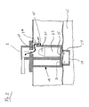
- the bleed valve 1 which is partially shown schematically in the figures, is inserted into a mounting opening 2 in the upper wall 3 of a fuel tank 4. It rests with a flange 5 on the outside 6 of the wall 3 of the fuel tank 4.
- the flange 5 is one of the loading and Venting the tank interior 7 serving vent opening 8 passes.
- He carries a connecting piece 9, which is connected via a line 10 with an activated carbon canister 13, which communicates with the environment, for example via a line 12.
- the connection piece 9, the lines 10, 12, the activated carbon container 13 and the line 14 are components of the ventilation system of the fuel tank 4.
- a housing 14 On the underside of the flange 5, a housing 14 is attached, which has a valve housing 15 and a storage container 16 which are integral components of the housing 14, preferably a plastic injection molded part. It is also conceivable, however, a separate, arranged within the fuel tank storage tank.
- the interior 17 of the storage container 16 is delimited by a partition 21 from the interior 18 of the valve housing 15 and connected to the ventilation system of the fuel tank 4.
- the valve housing 15 and the storage container 16 are closed on the underside by a common bottom 19.
- In the valve housing 15 is a on its upper side a sealing element 20 supporting float 23 between a rest position ( Fig. 1 ) and a closed position ( Fig. 4 ) movably mounted. In the rest position, the sealing element 20 releases the vent opening 8, while in the closed position it is pressed against the vent opening 8 by the float 23 raised due to buoyancy forces and closes it.
- the vent valve 1 is designed such that a gas exchange serving for ventilation and venting can take place only at a position of the valve housing which is close to the upper tank wall 3 or the vent opening 8.
- an opening is present in the said area, because of their later explained in more detail function, namely to allow access of fuel into the interior 7 of the valve housing 15, is referred to as the inlet opening 24.
- Other openings that allow the entry of fuel into the valve housing 15 are not present.
- the bottom 19 of the housing 14 are emptying openings 25, 26 available, the function will be explained later in more detail.
- penetration of fuel into these openings is prevented by a shut-off valve 27 arranged outside at the bottom 19. This has below an opening 28 through which fuel can penetrate into its interior 29.
- a floating, formed approximately in the form of a circular disc sealing element 30 is present.
- the sealing element 30 floats.
- the upper side of the sealing element 30 is embodied, for example, level and interacts with a sealing seat 34 encompassing the two emptying openings 25, 26.
- Sealing seat 34 and sealing element 30 are configured so that in the closed position between the sealing element 30 and the discharge openings 26, 25 a cavity connecting these openings is present. For example, one of the discharge openings 25, 26 interconnecting groove 35 in the bottom 19 is present.
- the discharge openings 26, 25 together with the groove 35 form a connecting channel 36 which extends between the discharge openings 25, 26 and the interior 18 of the Ventilge-housing 15 connects to the interior 17 of the storage container 16.
- the discharge openings 25, 26 are controlled by a common shut-off valve or sealing element.
- each opening is assigned its own shut-off valve.
- the lower edge 39 of the skirt 37 extends - based on the installed state of the vent valve 1 - substantially in a horizontal plane or in a direction perpendicular to the central longitudinal axis 40 of the valve housing 15 extending plane.
- the skirt 37 is on lateral or in the circumferential direction of the valve housing 15 opposite edge portions 43 (see Fig. 7 ) of the input opening 24 is formed.
- the inlet opening 24 has a lower edge 44 which also extends in a horizontal plane or in a plane extending at right angles to the central longitudinal axis 40 of the valve housing 15.
- a fuel tank 4 equipped with a bleed valve 1 of the type described operates as follows:
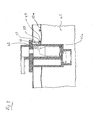
- the fuel level 33 approximately from the fuel level 33 in FIG Fig. 1 initially increases, the sealing element 30 of the shut-off valve 27 floats on and closes the emptying openings 25, 26, so that no fuel 45 can get into the storage tank 16 or the valve housing 15 ( Fig. 2 ).
- the displaced by the rising fuel gas flows between the skirt 37 and the valve housing 15 into the inlet port 24 and leaves the fuel tank 4 via the vent opening 8, which is indicated by the arrow 46 in FIG Fig. 2 is indicated.
- fuel 45 has already risen so far that it has almost reached the lower edge 39 of the skirt 37.
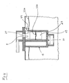
- the skirt 37 extends downwardly beyond the inlet opening 24, that is, if its lower edge 39 is arranged geodetically below the lower edge 44 of the inlet opening shown closed position of the float 23.
- fuel level 33c in Fig. 4 After the closure of the vent opening 8 flowing fuel increases the fuel level at best only slightly (fuel level 33c in Fig. 4 ), whereby an internal tank pressure builds up and fuel in the filler pipe (not shown) of the fuel tank rises and causes a shutdown of the fuel nozzle.
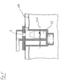
- fuel flows into the storage tank 16, so that the closure of the vent opening 8 causing fuel level 33b (closing level) decreases, at the end in the valve housing 15 and the reservoir 16 leveled fuel level 33d are present ( Fig. 5 ).
- the float 23 is again in its rest position, in which he gives the vent 8 free.
- the flow cross-sections of the discharge openings 25, 26 and the groove 35 connecting them to each other are selected so that the level compensation in the valve housing 15th and storage tank 16 is relatively slow, such as within a period of several seconds. Only then is a refueling possible, for example, to round up the amount to be paid to a smooth amount.
- the absorption capacity of the storage container 16 may be such that the in Fig. 5 shown state is reached after several refills. Is based on the in Fig. 5 shown situation, the vehicle put into operation, it is due to the already open at this time vent 8 refueling at any time, so for example already after a short drive easily possible. It is also conceivable that an active emptying is provided for the storage container 16, that it is connected for example to an existing in the fuel tank suction jet pump, which may be controlled depending on the fuel level in the storage tank.
- Fig. 6 to 11 is a concrete embodiment of a vent valve 1a shown in different views, but with flange 5 and 9 are omitted. To fix them on the upper side of the housing 4a, an approximately cylindrical extension 49 is present.
- the storage container 16a and the valve housing 15a are components of a one-piece plastic injection-molded part.
- the reservoir 16a coaxially surrounds the substantially cylindrical valve housing 15a on a part of its circumference (about 250 °).
- the inlet openings 24a there are two webs 54, which enclose a groove 53 between them and run parallel to the central longitudinal axis 40 of the valve housing 15a, which protrude approximately radially out of the peripheral section 50.
- the circumferentially facing ends of the storage container 16a are formed by approximately radially and axially extending wall webs 55.
- the areas of the wall webs 55 projecting beyond the lower edge 44 of the inlet openings 24a in the direction of the cover 38 of the housing 4a form edge areas 43 of the inlet openings 24a.
- Two further edge regions 43a are formed by the circumferentially facing side walls 56 of the webs 54.
- the shut-off valve 27 a has a plurality of openings 28.
- the sealing element 30a of the shut-off valve 27a is designed substantially cup-shaped, with its upper side carries a flat elastomeric disk 59.
- the existing at the bottom 19 of the housing 4 sealing seat 34a projects rib-shaped from the bottom 19.
- a cavity 60 connecting the two emptying openings 25, 26 is thereby present between the sealing element 34a, this forming the connecting channel 36a together with the emptying openings 25, 26.
- the float 23 has a central cavity 63 in which a helical compression spring 64 is arranged. This serves to ensure a roll-over function in an accidental head position of the motor vehicle.
- the upper side of the float 23 existing sealing element 20a is formed as a multi-stage, for example as a two-stage sealing element.
Abstract
Description
Die Erfindung betrifft eine Entlüftungsvorrichtung für den Kraftstofftank eines Kraftfahrzeugs. Die Entlüftungsvorrichtung umfasst ein im Kraftstofftank angeordnetes Entlüftungsventil, das der Be- und Entlüftung dient. Im Gehäuse des Entlüftungsventils ist eine Be- und Entlüftungsöffnung vorhanden, die im Folgenden vereinfachend mit Entlüftungsöffnung bezeichnet wird. Das Entlüftungsventil ist in einer oberen Tankwand vorhanden, wobei die Entlüftungsöffnung mit der Atmosphäre in Verbindung steht. Das Entlüftungsventil ist als Schwimmerventil ausgestaltet, d.h. in seinem Gehäuse ist ein an seiner Oberseite ein mit der Entlüftungsöffnung zusammenwirkendes Dichtelement tragender Schwimmer zwischen einer Schließstellung und einer Ruhestellung beweglich gelagert. In der Ruhestellung ist der Schwimmer in einer unteren Position im Gehäuse angeordnet, wobei das Dichtelement von der Entlüftungsöffnung entfernt ist. Derartige Ventile dienen allgemein dazu, eine Entlüftungsöffnung zu verschließen, um einen Austritt von Kraftstoff zu vermeiden. Sie dienen beispielsweise auch dazu, den Füllstand des Kraftstoffs zu begrenzen. Beim Betanken, das über ein am Kraftstofftank vorhandenes Einfüllrohr erfolgt, wird der Schwimmer von dem ansteigenden Kraftstoff aufgrund von Auftriebskräften angehoben und gelangt letztlich in seine Schließstellung, in der er das Dichtelement mit einer mehr oder weniger großen Anpresskraft gegen die Entlüftungsöffnung drückt. Ab diesem Moment kann von dem in den Kraftstofftank einströmenden Kraftstoff verdrängtes Gas, gemeint ist damit ein Kraftstoff-Luft-Gemisch, nicht mehr über das Entlüftungs-ventil bzw. die Entlüftungsöffnung den Tank verlassen. Als Folge des weiter in den Kraftstofftank einfließenden Kraftstoffs steigt der Kraftstoffpegel zunächst weiter an, wodurch es zu einer Überfüllung kommt, d.h. dass das vom Schwimmer verdrängte Kraftstoffvolumen zunimmt, dass der Schwimmer also mehr als erforderlich in den Kraftstoff eintaucht, was mit einer entsprechenden Zunahme der auf das Dichtelement wirkenden Anpresskraft verbunden ist. Schließlich kommt es durch im Einfüllrohr des Kraftstofftanks aufsteigenden Kraftstoff bei einem bestimmten Kraftstoffpegel, dem Abschaltpegel, zu einem Abschalten der Zapfpistole.The invention relates to a ventilation device for the fuel tank of a motor vehicle. The venting device comprises a venting valve arranged in the fuel tank, which serves for the ventilation. In the housing of the vent valve, a ventilation opening is present, which is referred to in the following simplifying with vent. The vent valve is present in an upper tank wall, with the vent opening communicating with the atmosphere. The vent valve is configured as a float valve, that is, in its housing, a floating on the upper side of a cooperating with the vent sealing element between a closed position and a rest position is movably mounted. In the rest position, the float is arranged in a lower position in the housing, wherein the sealing element is removed from the vent opening. Such valves generally serve to close a vent opening to prevent leakage of fuel. They also serve, for example, to limit the level of the fuel. When refueling, which takes place via a filler pipe present on the fuel tank, the float is lifted by the rising fuel due to buoyancy forces and ultimately reaches its closed position in which he presses the sealing element with a more or less large contact force against the vent opening. From this moment on, the gas flowing into the fuel tank can mean displaced gas a fuel-air mixture, no longer leave the tank via the vent valve or the vent opening. As a result of further flowing into the fuel tank fuel, the fuel level initially continues to increase, which leads to overfilling, ie that the volume of fuel displaced by the float increases, so that the float is immersed more than necessary in the fuel, which with a corresponding increase in connected to the sealing element acting pressing force is connected. Finally, fuel rising in the filler tube of the fuel tank will turn off the fuel nozzle at a certain fuel level, the shutdown level.
Aufgrund der genannten Überfüllung beim Betanken und gegebenenfalls auch durch einen sich beim Fahrzeugbetrieb aufbauenden Tankinnendruck ist das Wiederöffnen der Entlüftungsöffnung mit einer Hysterese (Wiederbetankungshysterese) behaftet, d.h. die Entlüftungsöffnung bleibt so lange verschlossen, bis der Kraftstoff durch Verbrauch auf einen niedrigeren Pegel, dem Öffnungspegel abgesunken ist. Je nach der horizontalen Querschnittsfläche des Kraftstofftanks ist dieser erst bei einem Verbrauch von mehreren Litern Kraftstoff, beispielsweise von 6 Litern und mehr, erreicht. Dies ist zum einen nachteilig, weil für eine relativ lange Betriebsphase im Tank ein gegebenenfalls diesen schädigender Tankinnendruck vorhanden ist. Zum anderen führt der genannte Effekt im Mietwagengeschäft dazu, dass nach kürzeren Fahrstrecken ein Wiederbetanken des Mietwagens nicht möglich ist, so dass der Verbrauch zu Lasten des nächsten Kunden oder des Vermieters geht.Due to the above overfilling during refueling and possibly also by an internal tank pressure which builds up during vehicle operation, the reopening of the vent opening is subject to a hysteresis (refueling hysteresis), i. the vent remains closed until the fuel has dropped to a lower level, the opening level, due to consumption. Depending on the horizontal cross-sectional area of the fuel tank this is only at a consumption of several liters of fuel, for example, of 6 liters and more, achieved. This is on the one hand disadvantageous because for a relatively long operating phase in the tank an optionally this damaging internal tank pressure is present. On the other hand, the effect mentioned in the rental car business means that refueling of the rental car is not possible after shorter journeys, so that consumption is at the expense of the next customer or the lessor.
Davon ausgehend ist es die Aufgabe der Erfindung, eine Entlüftungsvorrichtung für den Kraftstofftank eines Kraftfahrzeugs vorzuschlagen, mit der die genannten Nachteile umgangen werden können.On this basis, it is the object of the invention, a ventilation device for the fuel tank of a motor vehicle to propose, with which the mentioned disadvantages can be avoided.
Diese Aufgabe wird durch eine Entlüftungsvorrichtung nach Anspruch 1 gelöst. Diese umfasst, wie bereits erwähnt, ein Entlüftungsventil mit einem eine Entlüftungsöffnung aufweisenden Ventilgehäuse. In diesem ist an einer oberen, der Entlüftungsöffnung nahen Position wenigstens eine dem Gas- und Kraftstoffdurchtritt dienende Einlassöffnung, und an einer unteren Position wenigstens eine Entleerungsöffnung vorhanden. Ansonsten sind in dem sich zwischen den genannten Öffnung erstreckenden Gehäusebereich keine weiteren Öffnungen eingebracht. Damit beim Betanken kein Kraftstoff über die Entleerungsöffnung in den Innenraum des Ventilgehäuses eindringen kann, ist dieses von einem Dichtelement eines Absperrventils verschließbar. Auf welche Weise das Absperrventil arbeitet ist im Prinzip unerheblich. So ist beispielsweise ein elektromagnetisch betätigtes Ventil denkbar. Bevorzugt wird jedoch ein Ventil mit einem aufschwimmenden Dichtelement eingesetzt, da ein solches Ventil bei geringem Herstellungs- und Montageaufwand zuverlässig arbeitet. Durch die bisher beschriebene Ausgestaltung wird erreicht, dass der Kraftstoff im Tank auf einen Pegel ansteigen kann, der höher liegt als der zum Verschluss der Entlüftungsöffnung innerhalb des Ventilgehäuses erforderliche Kraftstoff- bzw. Schließpegel. Der Schwimmer bleibt mangels im Ventilgehäuse vorhandenen Kraftstoffs zunächst in seiner Ruhestellung. Erst wenn der Kraftstoff die weit oben, oberhalb des Schließpegels am Entlüftungsventil angeordnete Einlassöffnung erreicht, kann Kraftstoff in den Innenraum des Ventilgehäuses hineinlaufen und den Schwimmer in seine Schließstellung anheben. Die bisher beschriebene Ausgestaltung hätte zwar den Vorteil eines höheren Kraftstoff-Füllstandes im Tankinnenraum, also den Vorteil einer besseren Ausnutzung des Tankvolumens. Nachteilig wäre aber, dass sehr viel Kraftstoff im Fahrzeugbetrieb verbraucht werden müsste, damit der Kraftstoffpegel im Tank auf ein Niveau gesunken ist, bei dem das Absperrventil die Entleerungsöffnung im Ventilgehäuse freigibt und der Kraftstoff in den Tankinnenraum abfließen kann und der Schwimmer die Entlüftungsöffnung freigibt.This object is achieved by a ventilation device according to
Hier kommen nun weitere Gestaltungsmerkmale ins Spiel, die die Wiederbetankungshysterese deutlich verringern: Es ist ein im Tankinnenraum positionierbarer Speicherbehälter vorhanden, der über einen Verbindungskanal mit dem Innenraum des Ventilgehäuses verbunden ist, und zwar derart, dass darin vorhandener Kraftstoff in den Speicherbehälter abfließen kann, wobei der Strömungsquerschnitt des Verbindungskanals kleiner ist als der Öffnungsquerschnitt der Einlassöffnung. Aufgrund der genannten Abmessung des Verbindungskanals ist gewährleistet, dass der Kraftstoffabfluss in den Speicherbehälter das Anheben des Schwimmers in seine Schließstellung und den Verschluss der Entlüftungsöffnung nicht wesentlich beeinflusst. Nachdem die Entlüftungsöffnung verschlossen ist, kommt es durch ein Ansteigen des Kraftstoffs im Einfüllrohr zum Abschalten der Zapfpistole. Der Strömungsquerschnitt des Verbindungskanal ist nun weiterhin so ausgelegt, dass der im Innenraum des Ventilgehäuses vorhandene Kraftstoff innerhalb einer gewissen Zeitspanne, beispielsweise mehrerer Sekunden, in den Speicherbehälter läuft. Der Schwimmer kehrt dabei in seine Ruhestellung zurück, so dass - abhängig von der Aufnahmekapazität des Speicherbehälters mehrere Nachtankschritte möglich sind.Here are now other design features come into play that significantly reduce the refueling hysteresis: There is a positionable in the tank interior storage tank is connected via a connecting channel with the interior of the valve housing, in such a way that existing fuel can flow into the storage tank, wherein the flow cross section of the connecting channel is smaller than the opening cross section of the inlet opening. Due to the aforementioned dimension of the connecting channel, it is ensured that the fuel discharge into the storage container does not significantly affect the lifting of the float into its closed position and the closure of the vent opening. After the vent is closed, it comes through an increase in the fuel in the filler pipe to shut off the fuel nozzle. The flow cross-section of the connecting channel is now further designed so that the fuel present in the interior of the valve housing runs within a certain period of time, for example several seconds, into the storage container. The float returns to its rest position, so that - depending on the capacity of the storage container several refueling steps are possible.
Da die Aufnahmekapazität des Speicherbehälters begrenzt ist, muss eine Entleerung erfolgen. Zu diesem Zweck ist eine Entleerungseinrichtung vorhanden. Diese kann beispielsweise eine Absaugvorrichtung sein, etwa ein in einem Kraftstofftank ohnehin vorhandenes, eine Saugstrahlpumpe umfassendes Saugsystem. Vorzugsweise erfolgt die Entleerung jedoch über eine am Speicherbehälter vorhandene Entleerungsöffnung, die mit einem Dichtelement eines Absperrventils verschließbar ist.Since the capacity of the storage container is limited, emptying must be done. For this purpose, an emptying device available. This can be, for example, a suction device, such as an existing in a fuel tank anyway, a suction jet pump comprehensive suction system. Preferably, however, the emptying takes place via an emptying opening provided on the storage container, which can be closed with a sealing element of a shut-off valve.
In den Unteransprüchen sind vorteilhafte Ausgestaltungen angegeben, die in der folgenden, auf die beigefügten Zeichnungen Bezug nehmenden Beschreibung der Erfindung näher erläutert werden. Von den Zeichnungen zeigen:
- Fig. 1
- bis 5 schematische Abbildungen, die den grundsätzlichen Aufbau des Entlüftungsventils einer erfindungsgemäßen Entlüftungsvorrichtung sowie dessen Funktionsweise aufzeigen,
- Fig. 6
- ein konkretes Ausführungsbeispiel eines Entlüftungsventils in Seitenansicht,
- Fig. 7
- eine Draufsicht auf die Unterseite (Pfeil VII in
Fig. 6 ), - Fig. 8
- eine Draufsicht auf die Oberseite des Ventils (Pfeil VIII in
Fig. 6 ), - Fig. 9
- eine
Fig. 8 entsprechende Ansicht, wobei jedoch der Deckel des Entlüftungsventils entfernt ist, - Fig. 10
- einen Längsschnitt entsprechend Linie X-X in
Fig. 7 , - Fig. 11
- einen Längsschnitt entsprechend der Linie XI-XI in
Fig. 7 .
- Fig. 1
- to 5 are schematic illustrations showing the basic structure of the vent valve of a ventilation device according to the invention and its operation,
- Fig. 6
- a concrete embodiment of a vent valve in side view,
- Fig. 7
- a plan view of the bottom (arrow VII in
Fig. 6 ) - Fig. 8
- a top view of the top of the valve (arrow VIII in
Fig. 6 ) - Fig. 9
- a
Fig. 8 corresponding view, but with the cover of the vent valve removed, - Fig. 10
- a longitudinal section corresponding to line XX in
Fig. 7 . - Fig. 11
- a longitudinal section along the line XI-XI in
Fig. 7 ,
Das in den Abbildungen zum Teil schematisch dargestellte Entlüftungsventil 1 ist in eine Montageöffnung 2 in der oberen Wand 3 eines Kraftstofftanks 4 eingesetzt. Es liegt dabei mit einem Flansch 5 auf der Außenseite 6 der Wand 3 des Kraftstofftanks 4 auf. Der Flansch 5 ist von einer der Be- und Entlüftung des Tankinnenraums 7 dienenden Entlüftungsöffnung 8 durchsetzt. Er trägt einen Anschlussstutzen 9, der über eine Leitung 10 mit einem Aktivkohlebehälter 13 verbunden ist, wobei dieser beispielsweise über eine Leitung 12 mit der Umgebung in Verbindung steht. Der Anschlussstutzen 9, die Leitungen 10,12, der Aktivkohlebehälter 13 und die Leitung 14 sind Bestandteile des Entlüftungssystems des Kraftstofftanks 4.The
Unterseits am Flansch 5 ist ein Gehäuse 14 angesetzt, das ein Ventilgehäuse 15 und einen Speicherbehälter 16 aufweist, die integrale Bestandteile des Gehäuses 14, vorzugsweise ein Kunststoff-Spritzgussteil, sind. Denkbar ist aber auch ein separater, innerhalb des Kraftstofftanks angeordneter Speicherbehälter. Der Innenraum 17 des Speicherbehälters 16 ist durch eine Trennwand 21 von dem Innenraum 18 des Ventilgehäuses 15 abgegrenzt und an das Entlüftungssystem des Kraftstofftanks 4 angeschlossen. Das Ventilgehäuse 15 und der Speicherbehälter 16 sind unterseits von einem gemeinsamen Boden 19 verschlossen. Im Ventilgehäuse 15 ist ein auf seiner Oberseite ein Dichtelement 20 tragender Schwimmer 23 zwischen einer Ruhestellung (
Das Entlüftungsventil 1 ist so ausgestaltet, dass ein der Be-und Entlüftung dienender Gasaustausch lediglich an einer der oberen Tankwand 3 bzw. der Entlüftungsöffnung 8 nahen Position des Ventilgehäuses erfolgen kann. Zu diesem Zwecke ist in dem genannten Bereich eine Öffnung vorhanden, die wegen ihrer später noch genauer erläuterten Funktion, nämlich einen Zutritt von Kraftstoff in den Innenraum 7 des Ventilgehäuses 15 zu ermöglichen, als Einlassöffnung 24 bezeichnet wird. Weitere Öffnungen, die den Zutritt von Kraftstoff in das Ventilgehäuse 15 ermöglichen, sind nicht vorhanden. In dem Boden 19 des Gehäuses 14 sind zwar Entleerungsöffnungen 25, 26 vorhanden, deren Funktion später noch genauer erläutert wird. Ein Eindringen von Kraftstoff in diese Öffnungen ist aber durch ein außen am Boden 19 angeordnetes Absperrventil 27 verhindert. Dieses weist unterseits eine Öffnung 28 auf, durch die Kraftstoff in seinen Innenraum 29 eindringen kann. Im Innenraum 29 ist ein aufschwimmendes, etwa in Form einer kreisrunden Scheibe ausgebildetes Dichtelement 30 vorhanden. Wenn der Kraftstoffpegel 33, etwa ausgehend von der in
Ein mit einem Entlüftungsventil 1 der beschriebenen Art bestückter Kraftstofftank 4 arbeitet wie folgt: Wenn während des Betankens der Kraftstoffpegel 33, etwa ausgehend von der in
In
Wie insbesondere
- 11
- Entlüftungsventilvent valve
- 22
- Montageöffnungmounting hole
- 33
- Wandwall
- 44
- KraftstofftankFuel tank
- 55
- Flanschflange
- 66
- Oberseitetop
- 77
- TankinnenraumTank interior
- 88th
- Entlüftungsöffnungvent
- 99
- Anschlussstutzenspigot
- 1010
- Leitungmanagement
- 1212
- Leitungmanagement
- 1313
- AktivkohlebehälterActivated charcoal
- 1414
- Gehäusecasing
- 1515
- Ventilgehäusevalve housing
- 1616
- Speicherbehälterstorage container
- 1717
- Innenrauminner space
- 1818
- Innenrauminner space
- 1919
- Bodenground
- 2020
- Dichtelementsealing element
- 2121
- Trennwandpartition wall
- 2323
- Schwimmerswimmer
- 2424
- Einlassöffnunginlet port
- 2525
- Entleerungsöffnungemptying opening
- 2626
- Entleerungsöffnungemptying opening
- 2727
- Absperrventilshut-off valve
- 2828
- Öffnung (von 27)Opening (from 27)
- 2929
- Innenraum (von 27)Interior (from 27)
- 3030
- Dichtelementsealing element
- 3333
- KraftstoffpegelFuel level
- 3434
- Dichtsitzsealing seat
- 3535
- Nutgroove
- 3636
- Verbindungskanalconnecting channel
- 3737
- Schürzeapron
- 3838
- Deckelcover
- 3939
- Randedge
- 4040
- Mittellängsachse (von 15)Center longitudinal axis (from 15)
- 4343
- Randbereichborder area
- 4444
- Rand (unterer von 24)Edge (lower of 24)
- 4545
- Kraftstofffuel
- 4646
- Pfeilarrow
- 4747
- Spaltgap
- 4848
- Tropfendrops
- 4949
- Fortsatzextension
- 5050
- Umfangsabschnittperipheral portion
- 5353
- Nutgroove
- 5454
- Doppelstegdouble bridge
- 5555
- Wandstegwall web
- 5656
- SeitenwandSide wall
- 5858
- Axialspaltaxial gap
- 5959
- Elastomerscheibeelastomer disk
- 6060
- Hohlraumcavity
- 6363
- Hohlraumcavity
- 6464
- SchraubendruckfederHelical compression spring
Claims (16)
gekennzeichnet durch
folgende weitere Ausgestaltung:
marked by
following further embodiment:
dadurch gekennzeichnet,
dass das Absperrventil (27) ein aufschwimmendes Dichtelement (30) aufweist.Ventilation device according to claim 1,
characterized,
that the shut-off valve (27) comprises a aufschwimmendes sealing element (30).
dadurch gekennzeichnet,
dass mit Radialabstand vor der Einlassöffnung (24) eine sich vertikal erstreckende, zumindest einen Teil der Öffnungsfläche der Einlassöffnung (24) überdeckende Schürze (37) vorhanden ist.A ventilation device according to claim 1 or 2,
characterized,
that with radial spacing in front of the inlet opening (24) there is a vertically extending skirt (37) covering at least part of the opening area of the inlet opening (24).
dadurch gekennzeichnet,
dass die Schürze an seitlichen Randbereichen (43) der Eingangsöffnung (24) angeformt ist.Ventilation device according to claim 3,
characterized,
that the skirt is formed on lateral edge regions (43) of the inlet opening (24).
dadurch gekennzeichnet,
dass die Entleerungseinrichtung eine im Speicherbehälter vorhandene Entleerungsöffnung (26) und ein diese mit einem Dichtelement (30) verschließendes Absperrventil (27) umfasst.Ventilation device according to one of the preceding claims,
characterized,
that the emptying device in an existing storage tank discharge opening (26) and this with a sealing element (30) closing off valve (27).
gekennzeichnet durch
ein aufschwimmendes Dichtelement (30).Ventilation device according to claim 5,
marked by
a floating sealing element (30).
dadurch gekennzeichnet,
dass die Entleerungseinrichtung eine Saugeinrichtung ist.Ventilation device according to one of claims 1 to 6,
characterized,
that the emptying device is a suction device.
dadurch gekennzeichnet,
dass der Speicherbehälter (16) mit der Atmosphäre in Verbindung steht.Ventilation device according to one of the preceding claims,
characterized,
that the storage container (16) is in communication with the atmosphere.
dadurch gekennzeichnet,
dass der Speicherbehälter (16) mit einem Be- und Entlüftungssystem des Kraftstofftanks (4) verbunden ist.Ventilation device according to claim 8,
characterized,
that the storage container (16) with a ventilation system of the fuel tank (4) is connected.
dadurch gekennzeichnet,
dass die Entleerungsöffnung (25) des Ventilgehäuses (15) und die Entleerungsöffnung (26) des Speicherbehälters (16) von einem gemeinsamen Dichtelement (30) verschließbar sind.Ventilation device according to one of the preceding claims in conjunction with claims 1 and 5,
characterized,
that the emptying opening (25) of the valve housing (15) and the discharge opening (26) of the storage container (16) by a common sealing element (30) can be closed.
dadurch gekennzeichnet,
dass das Dichtelement (30) mit einem die Entleerungsöffnungen (25, 26) umgreifenden Ventilsitz (34) zusammenwirkt, wobei der Ventilgehäuse (15) und Speicherbehälter miteinander verbindende Verbindungskanal (36) innerhalb eines von dem Ventilsitz (34) umgriffenen Bereichs angeordnet ist und sich zwischen den genannten Öffnungen (25, 26) erstreckt..Ventilation device according to claim 10,
characterized,
in that the sealing element (30) interacts with a valve seat (34) encompassing the emptying openings (25, 26), wherein the valve housing (15) and storage container interconnecting connecting channel (36) is arranged within a region encompassed by the valve seat (34) and extends between said openings (25, 26) ..
dadurch gekennzeichnet,
dass die Entleerungsöffnungen (25,26) auf der Unterseite eines dem Ventilgehäuse (15) und dem Speicherbehälter (16) gemeinsamen Bodens (19) ausmünden.Ventilation device according to claim 10 or 11,
characterized,
in that the emptying openings (25, 26) open out on the underside of a bottom (19) common to the valve housing (15) and the storage container (16).
dadurch gekennzeichnet,
dass der Speicherbehälter (16a) das zylindrisch ausgebildete Ventilgehäuse (15a) zumindest auf einem Teil seines Umfangs umfasst.Ventilation device according to one of the preceding claims,
characterized,
that the storage container (16a) comprises cylindrically shaped valve housing (15a) at least on a part of its circumference.
dadurch gekennzeichnet,
dass die wenigstens eine Einlassöffnung 24a des Ventilgehäuses (15a) in einem vom Speicherbehälter (16a) freigelassenen Umfangsabschnitt (50) des Ventilgehäuses (15a) angeordnet ist.Ventilation device according to claim 13,
characterized,
in that the at least one inlet opening 24a of the valve housing (15a) is arranged in a peripheral section (50) of the valve housing (15a) left free by the storage tank (16a).
dadurch gekennzeichnet,
dass sich die Schürze (37) zwischen den in Umfangsrichtung weisenden Enden des Speicherbehälters (16a) erstreckt.Ventilation device according to claim 14 in conjunction with claim 3,
characterized,
in that the skirt (37) extends between the circumferentially facing ends of the storage container (16a).
dadurch gekennzeichnet,
dass der Speicherbehälter (16) und das Ventilgehäuse (15) einstückig miteinander verbunden sind.Ventilation device according to one of the preceding claims,
characterized,
in that the storage container (16) and the valve housing (15) are integrally connected to one another.
Applications Claiming Priority (2)
| Application Number | Priority Date | Filing Date | Title |
|---|---|---|---|
| DE102007030039 | 2007-06-27 | ||
| DE200710050970 DE102007050970B4 (en) | 2007-06-27 | 2007-10-25 | Ventilation device for the fuel tank of a motor vehicle |
Publications (3)
| Publication Number | Publication Date |
|---|---|
| EP2008858A2 true EP2008858A2 (en) | 2008-12-31 |
| EP2008858A3 EP2008858A3 (en) | 2011-10-12 |
| EP2008858B1 EP2008858B1 (en) | 2012-07-25 |
Family
ID=39864751
Family Applications (1)
| Application Number | Title | Priority Date | Filing Date |
|---|---|---|---|
| EP20080010776 Not-in-force EP2008858B1 (en) | 2007-06-27 | 2008-06-13 | Ventilation device for the fuel tank of a motor vehicle |
Country Status (1)
| Country | Link |
|---|---|
| EP (1) | EP2008858B1 (en) |
Cited By (1)
| Publication number | Priority date | Publication date | Assignee | Title |
|---|---|---|---|---|
| CN109538800A (en) * | 2018-11-09 | 2019-03-29 | 中国直升机设计研究所 | A kind of automatic exhaust steam valve and the fuel tank aerating system with it |
Families Citing this family (1)
| Publication number | Priority date | Publication date | Assignee | Title |
|---|---|---|---|---|
| DE102022003912A1 (en) | 2022-10-21 | 2024-05-02 | BRUSS Sealing Systems GmbH | Ventilation module for a transmission of a particularly electrically powered motor vehicle |
Citations (6)
| Publication number | Priority date | Publication date | Assignee | Title |
|---|---|---|---|---|
| US5680848A (en) * | 1995-07-25 | 1997-10-28 | Honda Giken Kogyo Kabushiki Kaisha | Vaporized fuel control valve for fuel tank of internal combustion engine |
| DE19707841A1 (en) * | 1996-03-02 | 1997-10-30 | Alfmeier Walter Gmbh & Co | Spring loaded float-operated breather valve for fuel tanks of vehicles |
| DE19921665A1 (en) * | 1999-05-11 | 2000-11-30 | Alfmeier Praez Ag | Venting valve for vehicle fuel tank, float of which has longitudinal sector of greater diameter close to or above venting channel |
| US20050126633A1 (en) * | 2003-12-04 | 2005-06-16 | Ralf Leonhardt | Fill limit vent valve |
| US20050284539A1 (en) * | 2004-06-28 | 2005-12-29 | Ralf Leonhardt | Fill limit vent valve assembly |
| DE202005020971U1 (en) * | 2005-08-05 | 2006-12-21 | Alfmeier Präzision AG Baugruppen und Systemlösungen | Ventilating valve for a fuel container of motor vehicles comprises two outlet openings surrounded by seal seats, and a flexible membrane functioning as a seal with these openings |
-
2008
- 2008-06-13 EP EP20080010776 patent/EP2008858B1/en not_active Not-in-force
Patent Citations (6)
| Publication number | Priority date | Publication date | Assignee | Title |
|---|---|---|---|---|
| US5680848A (en) * | 1995-07-25 | 1997-10-28 | Honda Giken Kogyo Kabushiki Kaisha | Vaporized fuel control valve for fuel tank of internal combustion engine |
| DE19707841A1 (en) * | 1996-03-02 | 1997-10-30 | Alfmeier Walter Gmbh & Co | Spring loaded float-operated breather valve for fuel tanks of vehicles |
| DE19921665A1 (en) * | 1999-05-11 | 2000-11-30 | Alfmeier Praez Ag | Venting valve for vehicle fuel tank, float of which has longitudinal sector of greater diameter close to or above venting channel |
| US20050126633A1 (en) * | 2003-12-04 | 2005-06-16 | Ralf Leonhardt | Fill limit vent valve |
| US20050284539A1 (en) * | 2004-06-28 | 2005-12-29 | Ralf Leonhardt | Fill limit vent valve assembly |
| DE202005020971U1 (en) * | 2005-08-05 | 2006-12-21 | Alfmeier Präzision AG Baugruppen und Systemlösungen | Ventilating valve for a fuel container of motor vehicles comprises two outlet openings surrounded by seal seats, and a flexible membrane functioning as a seal with these openings |
Cited By (1)
| Publication number | Priority date | Publication date | Assignee | Title |
|---|---|---|---|---|
| CN109538800A (en) * | 2018-11-09 | 2019-03-29 | 中国直升机设计研究所 | A kind of automatic exhaust steam valve and the fuel tank aerating system with it |
Also Published As
| Publication number | Publication date |
|---|---|
| EP2008858B1 (en) | 2012-07-25 |
| EP2008858A3 (en) | 2011-10-12 |
Similar Documents
| Publication | Publication Date | Title |
|---|---|---|
| DE102007050970B4 (en) | Ventilation device for the fuel tank of a motor vehicle | |
| EP2300256B1 (en) | Insert element for a container suitable for filling with urea at a filling station | |
| DE19651117C2 (en) | Gas venting device for a fuel tank | |
| DE19850662A1 (en) | Gasoline tank vapor emission control valve | |
| DE3943200C2 (en) | Built-in fuel pump with level control | |
| DE10247791A1 (en) | Vapor vent and rollover valve for motor vehicle fuel tank has float that progressively closes vapor outlet to vent fuel vapor or fill fuel tank, and body that closes remainder of valve upon rollover to prevent escape of liquid fuel | |
| DE102011011167B4 (en) | Fuel system with means for controlling a suction jet pump as a function of the fuel level in a delivery or swirl pot of a fuel tank | |
| AT508043B1 (en) | VEHICLE TANK | |
| DE1916788A1 (en) | Ventilation system for crankcase | |
| DE10148506A1 (en) | Vapor vent valve for a vehicle fuel tank has two floats that close portions of the tank vapor outlet in response to the liquid fuel level and baffles to prevent liquid fuel flow through the vapor outlet | |
| DE102007028480A1 (en) | SCR device | |
| EP2379361A1 (en) | Fuel tank having a built-in auxiliary tank | |
| DE60103370T2 (en) | VENTILATION VALVE FOR A FUEL TANK | |
| DE102008014820A1 (en) | Fuel tank for motor vehicles | |
| DE10209491A1 (en) | Fuel tank with venting system has inlet opening in form of open line end and liquid separator arranged between inlet opening and active carbon filter | |
| DE19836104A1 (en) | Filling tube for motor vehicle fuel tank | |
| EP2008858B1 (en) | Ventilation device for the fuel tank of a motor vehicle | |
| DE102016222517B4 (en) | fuel tank system | |
| DE19621031A1 (en) | Device to assist fuel filling and fuel vapour trap for motor vehicle fuel-tank - has device with valve to allow fuel vapour from tank to collect in canister plus one=way valve on filling pipe | |
| DE112021003205T5 (en) | Improved fuel tank shut-off valve with inter-position locking for single operation | |
| EP2842785B1 (en) | Commercial vehicle tank | |
| DE102005053815A1 (en) | De-aeration unit for aerating and de-aerating e.g. liquid fuel tank, has supply port connected with activated carbon filter, and bypass line discharging fuel to de-aeration pipe, where throttle is provided in bypass line | |
| DE19952926A1 (en) | Safety valve for fuel tank of car, comprising ball cage system for avoidance of leakage in case of somersault, not interfering with filling process | |
| EP2008857B1 (en) | Fuel tank for motor vehicles | |
| WO2003086805A1 (en) | Petrol cap |
Legal Events
| Date | Code | Title | Description |
|---|---|---|---|
| PUAI | Public reference made under article 153(3) epc to a published international application that has entered the european phase |
Free format text: ORIGINAL CODE: 0009012 |
|
| AK | Designated contracting states |
Kind code of ref document: A2 Designated state(s): AT BE BG CH CY CZ DE DK EE ES FI FR GB GR HR HU IE IS IT LI LT LU LV MC MT NL NO PL PT RO SE SI SK TR |
|
| AX | Request for extension of the european patent |
Extension state: AL BA MK RS |
|
| PUAL | Search report despatched |
Free format text: ORIGINAL CODE: 0009013 |
|
| AK | Designated contracting states |
Kind code of ref document: A3 Designated state(s): AT BE BG CH CY CZ DE DK EE ES FI FR GB GR HR HU IE IS IT LI LT LU LV MC MT NL NO PL PT RO SE SI SK TR |
|
| AX | Request for extension of the european patent |
Extension state: AL BA MK RS |
|
| RIC1 | Information provided on ipc code assigned before grant |
Ipc: B60K 15/035 20060101AFI20110905BHEP Ipc: F16K 24/04 20060101ALI20110905BHEP |
|
| 17P | Request for examination filed |
Effective date: 20111130 |
|
| GRAP | Despatch of communication of intention to grant a patent |
Free format text: ORIGINAL CODE: EPIDOSNIGR1 |
|
| GRAS | Grant fee paid |
Free format text: ORIGINAL CODE: EPIDOSNIGR3 |
|
| AKX | Designation fees paid |
Designated state(s): AT BE BG CH CY CZ DE DK EE ES FI FR GB GR HR HU IE IS IT LI LT LU LV MC MT NL NO PL PT RO SE SI SK TR |
|
| GRAA | (expected) grant |
Free format text: ORIGINAL CODE: 0009210 |
|
| AK | Designated contracting states |
Kind code of ref document: B1 Designated state(s): AT BE BG CH CY CZ DE DK EE ES FI FR GB GR HR HU IE IS IT LI LT LU LV MC MT NL NO PL PT RO SE SI SK TR |
|
| REG | Reference to a national code |
Ref country code: GB Ref legal event code: FG4D Free format text: NOT ENGLISH |
|
| REG | Reference to a national code |
Ref country code: CH Ref legal event code: EP |
|
| REG | Reference to a national code |
Ref country code: DE Ref legal event code: R082 Ref document number: 502008007753 Country of ref document: DE Representative=s name: MOERTEL, ALFRED, DIPL.-PHYS. DR.RER.NAT., DE Ref country code: DE Ref legal event code: R082 Ref document number: 502008007753 Country of ref document: DE Representative=s name: ALFRED MOERTEL, DE Ref country code: DE Ref legal event code: R082 Ref document number: 502008007753 Country of ref document: DE Representative=s name: MEISSNER BOLTE & PARTNER GBR, DE Ref country code: DE Ref legal event code: R082 Ref document number: 502008007753 Country of ref document: DE Representative=s name: MEISSNER BOLTE PATENTANWAELTE RECHTSANWAELTE P, DE |
|
| REG | Reference to a national code |
Ref country code: AT Ref legal event code: REF Ref document number: 567551 Country of ref document: AT Kind code of ref document: T Effective date: 20120815 Ref country code: IE Ref legal event code: FG4D Free format text: LANGUAGE OF EP DOCUMENT: GERMAN |
|
| REG | Reference to a national code |
Ref country code: DE Ref legal event code: R096 Ref document number: 502008007753 Country of ref document: DE Effective date: 20120920 |
|
| REG | Reference to a national code |
Ref country code: NL Ref legal event code: VDEP Effective date: 20120725 |
|
| REG | Reference to a national code |
Ref country code: LT Ref legal event code: MG4D Effective date: 20120725 |
|
| PG25 | Lapsed in a contracting state [announced via postgrant information from national office to epo] |
Ref country code: LT Free format text: LAPSE BECAUSE OF FAILURE TO SUBMIT A TRANSLATION OF THE DESCRIPTION OR TO PAY THE FEE WITHIN THE PRESCRIBED TIME-LIMIT Effective date: 20120725 Ref country code: IS Free format text: LAPSE BECAUSE OF FAILURE TO SUBMIT A TRANSLATION OF THE DESCRIPTION OR TO PAY THE FEE WITHIN THE PRESCRIBED TIME-LIMIT Effective date: 20121125 Ref country code: NO Free format text: LAPSE BECAUSE OF FAILURE TO SUBMIT A TRANSLATION OF THE DESCRIPTION OR TO PAY THE FEE WITHIN THE PRESCRIBED TIME-LIMIT Effective date: 20121025 Ref country code: FI Free format text: LAPSE BECAUSE OF FAILURE TO SUBMIT A TRANSLATION OF THE DESCRIPTION OR TO PAY THE FEE WITHIN THE PRESCRIBED TIME-LIMIT Effective date: 20120725 Ref country code: HR Free format text: LAPSE BECAUSE OF FAILURE TO SUBMIT A TRANSLATION OF THE DESCRIPTION OR TO PAY THE FEE WITHIN THE PRESCRIBED TIME-LIMIT Effective date: 20120725 Ref country code: CY Free format text: LAPSE BECAUSE OF FAILURE TO SUBMIT A TRANSLATION OF THE DESCRIPTION OR TO PAY THE FEE WITHIN THE PRESCRIBED TIME-LIMIT Effective date: 20120725 |
|
| PG25 | Lapsed in a contracting state [announced via postgrant information from national office to epo] |
Ref country code: SI Free format text: LAPSE BECAUSE OF FAILURE TO SUBMIT A TRANSLATION OF THE DESCRIPTION OR TO PAY THE FEE WITHIN THE PRESCRIBED TIME-LIMIT Effective date: 20120725 Ref country code: SE Free format text: LAPSE BECAUSE OF FAILURE TO SUBMIT A TRANSLATION OF THE DESCRIPTION OR TO PAY THE FEE WITHIN THE PRESCRIBED TIME-LIMIT Effective date: 20120725 Ref country code: PT Free format text: LAPSE BECAUSE OF FAILURE TO SUBMIT A TRANSLATION OF THE DESCRIPTION OR TO PAY THE FEE WITHIN THE PRESCRIBED TIME-LIMIT Effective date: 20121126 Ref country code: LV Free format text: LAPSE BECAUSE OF FAILURE TO SUBMIT A TRANSLATION OF THE DESCRIPTION OR TO PAY THE FEE WITHIN THE PRESCRIBED TIME-LIMIT Effective date: 20120725 Ref country code: PL Free format text: LAPSE BECAUSE OF FAILURE TO SUBMIT A TRANSLATION OF THE DESCRIPTION OR TO PAY THE FEE WITHIN THE PRESCRIBED TIME-LIMIT Effective date: 20120725 Ref country code: GR Free format text: LAPSE BECAUSE OF FAILURE TO SUBMIT A TRANSLATION OF THE DESCRIPTION OR TO PAY THE FEE WITHIN THE PRESCRIBED TIME-LIMIT Effective date: 20121026 |
|
| PG25 | Lapsed in a contracting state [announced via postgrant information from national office to epo] |
Ref country code: NL Free format text: LAPSE BECAUSE OF FAILURE TO SUBMIT A TRANSLATION OF THE DESCRIPTION OR TO PAY THE FEE WITHIN THE PRESCRIBED TIME-LIMIT Effective date: 20120725 |
|
| PG25 | Lapsed in a contracting state [announced via postgrant information from national office to epo] |
Ref country code: CZ Free format text: LAPSE BECAUSE OF FAILURE TO SUBMIT A TRANSLATION OF THE DESCRIPTION OR TO PAY THE FEE WITHIN THE PRESCRIBED TIME-LIMIT Effective date: 20120725 Ref country code: EE Free format text: LAPSE BECAUSE OF FAILURE TO SUBMIT A TRANSLATION OF THE DESCRIPTION OR TO PAY THE FEE WITHIN THE PRESCRIBED TIME-LIMIT Effective date: 20120725 Ref country code: ES Free format text: LAPSE BECAUSE OF FAILURE TO SUBMIT A TRANSLATION OF THE DESCRIPTION OR TO PAY THE FEE WITHIN THE PRESCRIBED TIME-LIMIT Effective date: 20121105 Ref country code: DK Free format text: LAPSE BECAUSE OF FAILURE TO SUBMIT A TRANSLATION OF THE DESCRIPTION OR TO PAY THE FEE WITHIN THE PRESCRIBED TIME-LIMIT Effective date: 20120725 Ref country code: RO Free format text: LAPSE BECAUSE OF FAILURE TO SUBMIT A TRANSLATION OF THE DESCRIPTION OR TO PAY THE FEE WITHIN THE PRESCRIBED TIME-LIMIT Effective date: 20120725 |
|
| PG25 | Lapsed in a contracting state [announced via postgrant information from national office to epo] |
Ref country code: SK Free format text: LAPSE BECAUSE OF FAILURE TO SUBMIT A TRANSLATION OF THE DESCRIPTION OR TO PAY THE FEE WITHIN THE PRESCRIBED TIME-LIMIT Effective date: 20120725 Ref country code: IT Free format text: LAPSE BECAUSE OF FAILURE TO SUBMIT A TRANSLATION OF THE DESCRIPTION OR TO PAY THE FEE WITHIN THE PRESCRIBED TIME-LIMIT Effective date: 20120725 |
|
| PLBE | No opposition filed within time limit |
Free format text: ORIGINAL CODE: 0009261 |
|
| STAA | Information on the status of an ep patent application or granted ep patent |
Free format text: STATUS: NO OPPOSITION FILED WITHIN TIME LIMIT |
|
| 26N | No opposition filed |
Effective date: 20130426 |
|
| PG25 | Lapsed in a contracting state [announced via postgrant information from national office to epo] |
Ref country code: BG Free format text: LAPSE BECAUSE OF FAILURE TO SUBMIT A TRANSLATION OF THE DESCRIPTION OR TO PAY THE FEE WITHIN THE PRESCRIBED TIME-LIMIT Effective date: 20121025 |
|
| REG | Reference to a national code |
Ref country code: DE Ref legal event code: R097 Ref document number: 502008007753 Country of ref document: DE Effective date: 20130426 |
|
| BERE | Be: lapsed |
Owner name: ALFMEIER PRAZISION A.G. BAUGRUPPEN UND SYSTEMLOSU Effective date: 20130630 |
|
| PG25 | Lapsed in a contracting state [announced via postgrant information from national office to epo] |
Ref country code: MC Free format text: LAPSE BECAUSE OF FAILURE TO SUBMIT A TRANSLATION OF THE DESCRIPTION OR TO PAY THE FEE WITHIN THE PRESCRIBED TIME-LIMIT Effective date: 20120725 |
|
| REG | Reference to a national code |
Ref country code: CH Ref legal event code: PL |
|
| GBPC | Gb: european patent ceased through non-payment of renewal fee |
Effective date: 20130613 |
|
| REG | Reference to a national code |
Ref country code: DE Ref legal event code: R082 Ref document number: 502008007753 Country of ref document: DE Representative=s name: MEISSNER BOLTE & PARTNER GBR, DE Ref country code: DE Ref legal event code: R082 Ref document number: 502008007753 Country of ref document: DE Representative=s name: MEISSNER BOLTE PATENTANWAELTE RECHTSANWAELTE P, DE |
|
| REG | Reference to a national code |
Ref country code: IE Ref legal event code: MM4A |
|
| PG25 | Lapsed in a contracting state [announced via postgrant information from national office to epo] |
Ref country code: BE Free format text: LAPSE BECAUSE OF NON-PAYMENT OF DUE FEES Effective date: 20130630 |
|
| PG25 | Lapsed in a contracting state [announced via postgrant information from national office to epo] |
Ref country code: CH Free format text: LAPSE BECAUSE OF NON-PAYMENT OF DUE FEES Effective date: 20130630 Ref country code: GB Free format text: LAPSE BECAUSE OF NON-PAYMENT OF DUE FEES Effective date: 20130613 Ref country code: LI Free format text: LAPSE BECAUSE OF NON-PAYMENT OF DUE FEES Effective date: 20130630 Ref country code: IE Free format text: LAPSE BECAUSE OF NON-PAYMENT OF DUE FEES Effective date: 20130613 |
|
| REG | Reference to a national code |
Ref country code: AT Ref legal event code: MM01 Ref document number: 567551 Country of ref document: AT Kind code of ref document: T Effective date: 20130613 |
|
| PG25 | Lapsed in a contracting state [announced via postgrant information from national office to epo] |
Ref country code: AT Free format text: LAPSE BECAUSE OF NON-PAYMENT OF DUE FEES Effective date: 20130613 |
|
| PG25 | Lapsed in a contracting state [announced via postgrant information from national office to epo] |
Ref country code: MT Free format text: LAPSE BECAUSE OF FAILURE TO SUBMIT A TRANSLATION OF THE DESCRIPTION OR TO PAY THE FEE WITHIN THE PRESCRIBED TIME-LIMIT Effective date: 20120725 |
|
| PG25 | Lapsed in a contracting state [announced via postgrant information from national office to epo] |
Ref country code: TR Free format text: LAPSE BECAUSE OF FAILURE TO SUBMIT A TRANSLATION OF THE DESCRIPTION OR TO PAY THE FEE WITHIN THE PRESCRIBED TIME-LIMIT Effective date: 20120725 |
|
| PG25 | Lapsed in a contracting state [announced via postgrant information from national office to epo] |
Ref country code: LU Free format text: LAPSE BECAUSE OF NON-PAYMENT OF DUE FEES Effective date: 20130613 Ref country code: HU Free format text: LAPSE BECAUSE OF FAILURE TO SUBMIT A TRANSLATION OF THE DESCRIPTION OR TO PAY THE FEE WITHIN THE PRESCRIBED TIME-LIMIT; INVALID AB INITIO Effective date: 20080613 |
|
| REG | Reference to a national code |
Ref country code: DE Ref legal event code: R082 Ref document number: 502008007753 Country of ref document: DE Representative=s name: MEISSNER BOLTE PATENTANWAELTE RECHTSANWAELTE P, DE |
|
| REG | Reference to a national code |
Ref country code: FR Ref legal event code: PLFP Year of fee payment: 9 |
|
| REG | Reference to a national code |
Ref country code: FR Ref legal event code: PLFP Year of fee payment: 10 |
|
| REG | Reference to a national code |
Ref country code: FR Ref legal event code: PLFP Year of fee payment: 11 |
|
| PGFP | Annual fee paid to national office [announced via postgrant information from national office to epo] |
Ref country code: DE Payment date: 20180625 Year of fee payment: 11 |
|
| PGFP | Annual fee paid to national office [announced via postgrant information from national office to epo] |
Ref country code: FR Payment date: 20180625 Year of fee payment: 11 |
|
| REG | Reference to a national code |
Ref country code: DE Ref legal event code: R119 Ref document number: 502008007753 Country of ref document: DE |
|
| PG25 | Lapsed in a contracting state [announced via postgrant information from national office to epo] |
Ref country code: DE Free format text: LAPSE BECAUSE OF NON-PAYMENT OF DUE FEES Effective date: 20200101 |
|
| PG25 | Lapsed in a contracting state [announced via postgrant information from national office to epo] |
Ref country code: FR Free format text: LAPSE BECAUSE OF NON-PAYMENT OF DUE FEES Effective date: 20190630 |