BACKGROUND OF THE INVENTION
1. Field of the Invention
This invention relates to a vaporized fuel control valve for a fuel tank of an internal combustion engine, more particularly to a vaporized fuel control valve for a fuel tank containing fuel to be supplied to an internal combustion engine, wherein a fuel spray from the tank which may be adhered to a diaphragm valve is prevented.
2. Description of the Related Art
A valve for controlling fuel vaporized from a fuel tank is known, wherein a filler port communicating chamber communicating with the vicinity of a filler port of the fuel tank (containing fuel to be supplied to an internal combustion engine) and a float valve communicating chamber communicating with a float valve opened by rise of the fuel level in the fuel tank are defined in a casing provided on the upper surface of the fuel tank, and a canister communicating port communicating the float valve communicating chamber with a canister is opened and closed by a diaphragm valve operated by the pressure difference between the filler port communicating chamber and the float valve communicating chamber. Such a device is proposed by the assignee in Japanese Laid-Open Patent Application No. Hei 8(1996)-100728.
When a fuel tank equipped with this prior-art vaporized fuel control valve is filled with fuel through a fuel gun (automatic nozzle) inserted into the filler port of the filler pipe, the pressure increase in the fuel tank produced by the rising fuel level is transmitted through the float valve and float valve communicating chamber to one side of the diaphragm valve. On the other hand, the filler port communicating chamber into which the other side surface of the diaphragm valve faces is in communication with the fuel tank filler port, which is at atmospheric pressure. A pressure difference thus arises between the float valve communicating chamber and the filler port communicating chamber, whereby the diaphragm valve operates to open the canister communicating port and communicate the float valve communicating chamber with the canister. As a result, the vaporized fuel in the fuel tank passes through the float valve, the float valve communicating chamber and the canister communicating port to the canister, where it is charged into activated carbon and thus prevented from escaping into the atmosphere.
As the supply of fuel to the tank is continued, the float valve is closed by the rising fuel level so that the fuel level in the filler pipe rises and causes the autostop device of the fuel gun to operate and stop the supply of fuel. When the fuel cap is replaced after removing the fuel gun from the filler port, the pressure difference between the filler port communicating chamber and the float valve communicating chamber falls to zero and the diaphragm valve closes to close the canister communicating port and cut off communication between the float valve communicating chamber and the canister.
In this prior-art vaporized fuel control valve, however, a fuel spray flying from the float valve at the time it is closed by the rising fuel level in the fuel tank sometimes invades the float valve communicating chamber and adheres to the diaphragm valve. The fuel adhering to the diaphragm valve may swell and degrade the rubber diaphragm, lowering its sealing property and durability.
This invention was accomplished in light of the foregoing circumstances and has as its object to provide a vaporized fuel control valve for a fuel tank of an intemal combustion engine, which by a simple structure reliably prevents fuel spray from the float valve from adhering to the diaphragm valve.
SUMMARY OF THE INVENTION
This invention achieves this object by providing a vaporized fuel control valve for a fuel tank containing fuel to be supplied to an internal combustion engine, comprising a casing fastened to an upper surface of the fuel tank, a float valve housed in the casing such that it moves upward toward a seat in response to fuel level in the fuel tank, a diaphragm valve placed in the casing above the float valve for separating an interior of the casing to a first chamber and a second chamber communicating with the fuel tank through the float valve, the diaphragm valve opening to connect the second chamber with a canister such that vaporized fuel forced out of the fuel tank passes along a path through the float valve to the canister unless the float valve seats on the seat. In the valve, there is provided an interceptor placed in the path to intercept a fuel spray so as the fuel spray not to adhere to the diaphragm valve.
BRIEF EXPLANATION OF THE DRAWINGS
The foregoing and other objects and advantages of the invention will be more apparent from the following description and drawings, in which:
FIG. 1 is a vertical sectional view of a vaporized fuel control valve for a fuel tank of an internal combustion engine according to a first embodiment of the invention;
FIG. 2 is a sectional view taken along line 2--2 in FIG. 1;
FIG. 3 is a vertical sectional view of a vaporized fuel control valve for a fuel tank of an internal combustion engine according to a second embodiment of the invention;
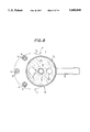
FIG. 4 is a sectional view taken along line 4--4 in FIG. 3;
FIG. 5 is a vertical sectional view of a vaporized fuel control valve for a fuel tank of an internal combustion engine according to a third embodiment of the invention;
FIG. 6 is a sectional view taken along line 6--6 in FIG. 5;
FIG. 7 is a vertical sectional view of a vaporized fuel control valve for a fuel tank of an internal combustion engine according to a fourth embodiment of the invention;
FIG. 8 is a sectional view taken along line 8--8 in FIG. 7;
FIG. 9 is a vertical sectional view of a vaporized fuel control valve for a fuel tank of an internal combustion engine according to a fifth embodiment of the invention;
FIG. 10 is a sectional view taken along line 10--10 in FIG. 9;
FIG. 11 is a vertical sectional view of a vaporized fuel control valve for a fuel tank of an internal combustion engine according to a sixth embodiment of the invention;
FIG. 12 is a sectional view taken along line 12--12 in FIG. 11;
FIG. 13 is a vertical sectional view of a vaporized fuel control valve for a fuel tank of an internal combustion engine according to a seventh embodiment of the invention;
FIG. 14 is a sectional view taken along line 14--14 in FIG. 13;
FIG. 15 is a vertical sectional view of a vaporized fuel control valve for a fuel tank of an internal combustion engine according to an eighth embodiment of the invention; and
FIG. 16 is a sectional view taken along line 16--16 in FIG. 15.
DETAILED DESCRIPTION OF THE PREFERRED EMBODIMENTS
Embodiments of the invention will now be explained with reference to the attached drawings.
FIGS. 1 and 2 show a vaporized fuel control valve for a fuel tank of an internal combustion engine according to a first embodiment of the invention. FIG. 1 is a vertical sectional view of the vaporized fuel control valve and FIG. 2 is a sectional view taken along 2--2 in FIG. 1.
As shown in FIGS. 1 and 2, the vaporized fuel control valve, designated by reference symbol V in the figures, is fit via a seal member 2 into a mounting hole 1 formed in the upper surface of the fuel tank T and fastened to the upper surface of a fuel tank T (containing fuel to be supplied to an internal combustion engine (not shown)) via a bracket 3 by stud bolts 4 rising from the fuel tank T and nuts 5. The vaporized fuel control valve V has a casing 6 comprising of a lower casing member 7 fastened to the fuel tank T by the stud bolts 4 and the nuts 5 and a upper casing member 8 united with the upper surface of the lower casing member 7 via an O-ring 9.
A float valve housing 71 provided on the lower casing member 7 fits into the fuel tank mounting hole 1, which is formed in the shape of a vertical cylindrical opening. A mounting flange 72 is formed at the upper end of the float valve housing 71 integrally therewith, and the stud bolts 4 pass through the mounting flange 72. An upward-opening dish-like diaphragm housing member 73 is formed integrally with the upper portion of the float valve housing 71. The diaphragm housing member 73 has a larger diameter than the float valve housing 71 and its axis is offset from the axis of the float valve housing 71.
A cylindrical wall 74 is formed integrally with the diaphragm housing member 73 at the center thereof. The lower end of the cylindrical wall 74 extends radially outward into a coupling member 75 which connects with a canister (not shown) of the engine.
The upper casing member 8 is formed with a downward-opening dish-like diaphragm housing member 81 and a coupling member 82 projecting radially outward from the diaphragm housing member 81. The coupling member 82 is connected with a filler pipe (not shown) of the fuel tank T near the filler port formed at the upper end thereof.
A floor plate 10 is fit in the opening at the lower end of the float valve housing 71 of the lower casing member 7 and a float valve 11 is disposed on the upper surface of the floor plate 10. The float valve 11 comprises a cylindrical float 12, a valve body 13 fixed on the upper surface of the float 12 and a spring 14 compressed between the floor plate 10 and the float 12 for applying an upward buoyancy-assisting force on the float 12. On the other hand, a valve seat 76 for the valve body 13 is formed at the upper end of the float valve housing 71. Communicating holes 77 and holes 101 are formed respectively in the side wall of the float valve housing 71 and the floor plate 10 so as to communicate the interior of the fuel tank T with the interior of the float valve housing 71.
A diaphragm valve 15 is disposed between the lower casing member 7 and the upper casing member 8. The diaphragm valve 15 comprises a diaphragm 16 clamped between the edge portions of the casing members 7, 8, a spring seat 17 overlying the upper surface of the diaphragm 16, a valve member 18 seatable on a valve seat 78 formed at the upper end of the cylindrical wall 74 to overlie the lower surface of the diaphragm 16, and a spring 19 compressed between the upper casing member 8 and the spring seat 17 to urge the valve member 18 toward the valve seat 78. The valve seat 78 constitutes a canister communication port in this embodiment.
In addition, a filler port communicating chamber or a first chamber R1 is defined between the upper surface of the diaphragm 16 and the upper casing member 8 to communicate with the filler pipe in the vicinity of the filler port via the coupling member 82, and a float valve communicating chamber or a second chamber R2 is defined under the diaphragm 16 to communicate with the float valve 11. When the diaphragm valve 15 is closed, i.e., when the valve member 18 is seated on the valve seat 78, as illustrated in FIG. 1, communication between the float valve communicating chamber or a second chamber R2 and the canister is cut off, while when the diaphragm valve 15 is open, i.e., when the valve member 18 is off the valve seat 78, the float valve communicating chamber R2 and the canister are in communication.
The float valve communicating chamber R2 is provided with a float valve communicating port 79 communicating with the interior of the float valve housing 71. A filter or interceptor 20 made of metal mesh or the like is installed in the upper end of the float valve communicating port 79.
The operation of the so-configured vaporized fuel control valve according to the first embodiment of the invention will now be explained.
In the normal state when fuel is not being supplied to the fuel tank T, the pressures in the filler port communicating chamber R1 and the float valve communicating chamber R2 are both equal to the pressure in the fuel tank T and, therefore, the valve member 18 of the diaphragm valve 15 is seated on the valve seat 78 by the force of the spring 19, cutting off communication between the float valve communicating chamber R2 and the canister.
When fuel is supplied to the tank from a fuel gun inserted into the filler port of the filler pipe, the pressure in the fuel tank T rises owing to the rising fuel level. As a result, the pressure in the float valve communicating chamber R2, which communicates with the interior of the fuel tank T through the float valve 11, also rises. On the other hand, the filler port communicating chamber R1 stays at atmospheric pressure owing to its communication with the filler pipe at a point near the filler port, which is at atmospheric pressure. The resulting pressure difference between the float valve communicating chamber R2 and the filler port communicating chamber R1 pushes the diaphragm 16 of the diaphragm valve 15 against the force of the spring 19, whereby the valve member 18 separates from the valve seat 78 to communicate or connect the float valve communicating chamber R2 with the canister.
As a result, the vaporized fuel forced out of the fuel tank T by the rising fuel level passes or flows through the float valve 11, the float valve communicating port 79, the filter 20, the float valve communicating chamber R2, the valve seat 78 and the coupling member 75 to the canister, where it is charged into activated carbon and thus prevented from escaping into the atmosphere.
When the fuel in the fuel tank T thereafter reaches the full level, it pushes up the float 12 and causes the valve body 13 to seat on the valve seat 76, cutting off communication between the interior of the fuel tank T and the float valve communicating chamber R2. Further supply of fuel therefore causes the fuel level in the filler pipe to rise rapidly and actuate the autostop device of the fuel gun. This stops the supply of fuel. When the fuel cap is replaced after removing the fuel gun from the filler port, the pressure difference between the filler port communicating chamber R1 and the float valve communicating chamber R2 falls to zero and the diaphragm valve 15 closes to cut off communication between the float valve communicating chamber R2 and the canister. The normal state is thus restored.
At the time the rising level of the fuel closes the float valve 11 to shut the float valve communicating port 79 of the float valve communicating chamber R2, the impact of the valve body 13 seating on the valve seat 76 may produce a fuel spray. Even if it does, however, the sprayed fuel is intercepted or blocked by the filter 20 and cannot reach the float valve communicating chamber R2. Since adherence of sprayed fuel to the diaphragm 16 of the diaphragm valve 15 located at the top of the float valve communicating chamber R2 can therefore be avoided, the diaphragm 16 can be prevented from experiencing decreased sealing property and durability owing to swelling and degradation.
The vaporized fuel control valve according to a second embodiment of the invention will now be explained with reference to FIGS. 3 and 4. Valve members of the second embodiment which are the same as those of the first embodiment will be assigned the same reference symbols as those in the first embodiment.
The vaporized fuel control according to the second embodiment comprises a doughnut-shaped partition 21 (a buffer plate or interceptor placed above the float valve 11 in a plane perpendicular to the direction in which the float 12 moves) that divides the float valve communicating chamber R2 into upper and lower sections. The partition 21 is formed at the center with a circular through-hole 211 that fits loosely around the cylindrical wall 74 so as to leave an annular gap 22 between the through-hole 211 and the cylindrical wall 74. As shown in FIG. 4, the float valve communicating port 79 and the gap 22 are offset from each other so as not to overlap in plan view.
Vaporized fuel in the fuel tank T can reach the upper section of the float valve communicating chamber R2 through the float valve housing 71, the float valve communicating port 79 and the gap 22 but fuel spray produced by the impact of the valve body 13 of the float 12 seating on the valve seat 76 is intercepted by the partition 21 and cannot reach the upper section of the float valve communicating chamber R2. Since adherence of sprayed fuel to the diaphragm 16 of the diaphragm valve 15 located at the top of the float valve communicating chamber R2 can therefore be avoided, the diaphragm 16 can be prevented from experiencing decreased sealing property and durability owing to swelling and degradation.
The vaporized fuel control valve according to a third embodiment of the invention will now be explained with reference to FIGS. 5 and 6. Valve members of the third embodiment which are the same as those of the first embodiment will be assigned the same reference symbols as those in the first embodiment.
In the valve according to the third embodiment, a fan-shaped mounting plate 710 is provided in the float valve communicating chamber R2 so as to surround the float valve communicating port 79. A cover 23 shaped like an inverted cup (and acting as the aforesaid buffer plate or intercepter) is removably fixed on the mounting plate 710 via legs 231. The cover 23 is closed at the top but is formed with four side through-holes 232.
Thus, vaporized fuel in the fuel tank T can reach the float valve communicating chamber R2 through the float valve housing 71, the float valve communicating port 79 and the through-holes 232 of the cover 23 but fuel spray produced by the impact of the valve body 13 of the float 12 seating on the valve seat 76 is intercepted by the cover 23 and cannot reach the float valve communicating chamber R2. Adherence of sprayed fuel to the diaphragm 16 is therefore prevented.
The vaporized fuel control valve according to a fourth embodiment of the invention will now be explained with reference to FIGS. 7 and 8. Valve members of the fourth embodiment which are the same as those of the first embodiment will be assigned the same reference symbols as those in the first embodiment.
The valve of the fourth embodiment is similar to that of the second embodiment but differs in the location of the through-hole 211 formed in the partition (intercepter) 21, which in the valve of this embodiment is provided on the opposite side of the cylindrical wall 74 from the float valve communicating port 79. The through-hole is thus provided at a position offset from the float valve communicating port 79.
As in the valve of the second embodiment, fuel spray produced by the impact of the valve body 13 of the float 12 seating on the valve seat 76 is intercepted by the partition 21 and cannot reach the float valve communicating chamber R2. Adherence of sprayed fuel to the diaphragm 16 is therefore prevented.
The vaporized fuel control valve according to a fifth embodiment of the invention will now be explained with reference to FIGS. 9 and 10. Valve members of the fifth embodiment which are the same as those of the first embodiment will be assigned the same reference symbols as those in the first embodiment.
The valve of the fifth embodiment is similar to that of the fourth embodiment but the partition (intercepter) 21 is formed with a plurality of through-holes, specifically two through- holes 211, 211 at positions offset from the float valve communicating port 79.
The valve of the fifth embodiment produces the same effect as that of the fourth embodiment.
The vaporized fuel control valve according to a sixth embodiment of the invention will now be explained with reference to FIGS. 11 and 12. Valve members of the sixth embodiment which are the same as those of the first embodiment will be assigned the same reference symbols as those in the first embodiment.
In the valve of the sixth embodiment, the partition or intercepter 21 is formed with a single through-hole 211 and a baffle plate 212 is disposed to extend vertically downward from the partition 21 at a point between the through-hole 211 and the float valve communicating port 79.
Fuel spray which passes upward through the float valve communicating port 79 to the bottom portion of the float valve communicating chamber R2 is accordingly blocked by the baffle plate 212 and cannot reach the through-hole 211 of the partition 21. Adherence of sprayed fuel to the diaphragm 16 is therefore prevented.
The vaporized fuel control valve according to a seventh embodiment of the invention will now be explained with reference to FIGS. 13 and 14. Valve members of the seventh embodiment which are the same as those of the first embodiment will be assigned the same reference symbols as those in the first embodiment.
In the valve of the seventh embodiment, the through-hole 211 of the partition or intercepter 21 is provided on the opposite side of the cylindrical wall 74 from the float valve communicating port 79, and the underside of the partition 21 is formed with two arcuate partitions 711, 712 enclosing about half the periphery of the float valve communicating port 79 and half the periphery of the through-hole 211. (The arcuate partitions are thus placed above the float valve 11 in a plane parallel with the direction in which the float 12 moves.) The lower portion (or a third chamber) of the float valve communicating chamber R2 is defined on one side of the two partitions 711, 712 (the side of the float valve communicating port 79 and the through-hole 211). A ceiling 213 is formed between the through-hole 211 and the partition 712 by establishing a prescribed distance L (illustrated in FIG. 14) between the periphery of the through-hole 211 and the partition 712.
Therefore, even if fuel spray should invade the lower portion of the float valve communicating chamber R2 from the float valve communicating port 79, pass in the direction of the arrow A in FIG. 14 and shoot upward upon collision with the partition 712, it will be intercepted by the ceiling 213 overhanging by the distance L and prevented from passing through the through-hole 211. As a result, adherence of sprayed fuel to the diaphragm 16 is even more reliably prevented.
The vaporized fuel control valve according to an eighth embodiment of the invention will now be explained with reference to FIGS. 15 and 16. Valve members of the eighth embodiment which are the same as those of the first embodiment will be assigned the same reference symbols as those in the first embodiment.
In the valve of the eighth embodiment, a lower or second partition 713 is provided below an upper partition 21 (corresponding to the partition or intercepter 21 of the second and fourth to seventh embodiments) integrally with the lower casing member 7, thereby defining the lower half of the float valve communicating chamber R2 below the lower partition 713, defining a (third) chamber communicating with the canister between the lower partition 713 and the upper partition 21, and forming the upper half of the float valve communicating chamber R2 above the partition 21. A cylindrical wall 714 is provided to rise from the lower partition 713 at a position offset 180° from the float valve communicating port 79. The upper and lower halves of the float valve communicating chamber R2 are communicated by a through-hole 715 formed inside the cylindrical wall 714.
The through-hole 715 formed within the vertically long cylindrical wall 714 of this eighth embodiment reliably prevents fuel spray from invading the upper half of the float valve communicating chamber R2.
The present invention has thus been shown and described with reference to specific embodiments. However, it should be noted that the present invention is in no way limited to the details of the described arrangements but changes and modifications may be made without departing from the scope of the appended claims.